JP2017190879A - Missile spinning system - Google Patents
Missile spinning system Download PDFInfo
- Publication number
- JP2017190879A JP2017190879A JP2016078788A JP2016078788A JP2017190879A JP 2017190879 A JP2017190879 A JP 2017190879A JP 2016078788 A JP2016078788 A JP 2016078788A JP 2016078788 A JP2016078788 A JP 2016078788A JP 2017190879 A JP2017190879 A JP 2017190879A
- Authority
- JP
- Japan
- Prior art keywords
- flying object
- flying
- peripheral surface
- barrel
- combustion gas
- Prior art date
- Legal status (The legal status is an assumption and is not a legal conclusion. Google has not performed a legal analysis and makes no representation as to the accuracy of the status listed.)
- Granted
Links
Images
Landscapes
- Toys (AREA)
Abstract
【課題】砲身に腔線(ライフル)が無くても、飛翔体を旋転させて発射できる飛翔体旋転システムを提供する。
【解決手段】内周面4aが滑らかな砲身4と、砲身4の砲腔内に後方から燃焼ガスを噴射する発射薬6と、内周面4aから半径方向内方に隙間Qを隔てて砲身4に装填される飛翔体8と、飛翔体8に取り付けられ互いに連通させながら砲腔を前後に仕切る回転装弾筒10と、を備える。回転装弾筒10は、その前後の砲腔を互いに連通させる。また回転装弾筒10は、飛翔体8の後方から隙間Qを介して砲身4の外部へ流れる燃焼ガスを回転力に変換して、飛翔体8と共に回転する回転機構10aを有する。
【選択図】図1
An object of the present invention is to provide a flying object turning system capable of turning and launching a flying object even if there is no cavity line (rifle) in the gun barrel.
A gun barrel with a smooth inner peripheral surface, a propellant that injects combustion gas into the canal of the gun barrel from behind, and a gun barrel that is spaced radially inward from the inner peripheral surface by a gap. 4 and a rotating bullet cylinder 10 that is attached to the flying body 8 and that divides the gun cavity forward and backward while communicating with each other. The rotary bullet cylinder 10 allows the front and rear gun cavities to communicate with each other. Further, the rotating bullet cylinder 10 has a rotating mechanism 10 a that converts combustion gas flowing from the rear of the flying object 8 through the gap Q to the outside of the barrel 4 into a rotational force and rotates together with the flying object 8.
[Selection] Figure 1
Description
本発明は、発射時に飛翔体を旋転させる飛翔体旋転システムに関する。 The present invention relates to a flying object rotation system that rotates a flying object at the time of launch.
砲弾やロケット弾などの飛翔体を飛行させる際には、飛翔姿勢を安定させるため、飛翔体を旋転させることがある。このような飛翔体を旋転させるシステムは、例えば特許文献1や非特許文献1に開示されている。 When flying a flying object such as a shell or a rocket, the flying object may be rotated to stabilize the flying posture. Such a system for rotating the flying object is disclosed in, for example, Patent Document 1 and Non-Patent Document 1.
特許文献1や非特許文献1に開示された砲身の内腔(以下、砲腔)には、弾丸に旋転を与えるための螺旋状の溝(以下、腔線(ライフル)という)が設けられる。この砲身に装填する弾丸には、砲腔の谷径より少し直径の大きい弾帯が設けられる。発射薬が発生する燃焼ガスの圧力が上昇することによって弾丸が砲腔内を移動すると、弾帯が腔線の山によって切れ、腔線に沿って回転しながら前進する。これにより弾丸が旋転する。
また腔線に弾帯が食い込むことにより、弾帯の前方への燃焼ガスの漏れが防止される。
The barrel of the gun barrel disclosed in Patent Document 1 and Non-Patent Document 1 (hereinafter referred to as the gun cavity) is provided with a spiral groove (hereinafter referred to as a cavity line (rifle)) for turning the bullet. The bullet loaded in the barrel is provided with a bullet band slightly larger in diameter than the valley diameter of the cannon. When the bullet moves in the cannon by increasing the pressure of the combustion gas generated by the propellant, the bullet band is cut by the crest of the cavity line and advances while rotating along the cavity line. This turns the bullet.
Further, the bullet band bites into the cavity line, thereby preventing the combustion gas from leaking to the front of the bullet band.
上述のように、特許文献1や非特許文献1のシステムは、弾丸を旋転させるために、砲身の内周面に腔線を有する。一般にこのような腔線を有する砲身を施線砲身という。施線砲身には、以下の特徴がある。 As described above, the systems of Patent Document 1 and Non-Patent Document 1 have a cavity line on the inner peripheral surface of the gun barrel in order to rotate the bullet. Generally, a gun barrel having such a cavity line is called a wire barrel. The wire barrel has the following characteristics.
(1)砲腔の内周面に腔線を設けるのに特殊な加工技術を必要とするため、滑腔砲身よりも製造費用が高くなる。 (1) Since a special processing technique is required to provide a cavity line on the inner peripheral surface of the canal cavity, the manufacturing cost is higher than that of the smooth barrel.
(2)腔線に弾帯が食い込んだ状態で弾丸が施線砲身内を進むため、弾丸の旋転の反作用によって、施線砲身には逆方向の回転力が作用する。そのためこの逆方向の回転力に対応するため、発射装置の総重量を重くする必要が生じる。 (2) Since the bullet advances in the wire barrel while the bullet band is biting into the cavity line, a reverse rotational force acts on the wire barrel due to the reaction of the bullet rotation. Therefore, it is necessary to increase the total weight of the launching device in order to cope with this reverse rotational force.
(3)腔線に弾帯が食い込んだ状態で弾丸が施線砲身内を進むため、弾丸が砲腔内を移動する際に生じる抵抗が大きく、燃焼ガスのガス圧力に対する弾丸の速度損失が大きい。
それゆえ、腔線をもたない滑腔砲身と同じ弾丸速度を得るためには、燃焼ガスのガス圧力の増加を必要とするため、腔線をもたない滑腔砲身より厚肉となり、発射装置の重量が重くなる。
(3) Since the bullet advances through the wire barrel while the bullet band is biting into the cavity line, the resistance generated when the bullet moves through the gun cavity is large, and the velocity loss of the bullet relative to the gas pressure of the combustion gas is large. .
Therefore, in order to obtain the same bullet velocity as a smooth barrel without a lumen line, it is necessary to increase the gas pressure of the combustion gas. The equipment becomes heavy.
そのため軽量で製造費用が安く、砲身に回転力が生じにくく、圧力損失が小さい飛翔体の旋転システムが求められていた。
そこで、砲身に腔線が無くても飛翔体を旋転させることができるシステムが求められた。
For this reason, there has been a demand for a flying object rotation system that is light in weight, low in manufacturing cost, less likely to generate rotational force in the gun barrel, and low in pressure loss.
Therefore, a system that can rotate the flying object even if there is no cavity line in the gun barrel is required.
本発明は上述した要望を満たすために創案されたものである。すなわち本発明の目的は、砲身に腔線が無くても、飛翔体を旋転させて発射できる飛翔体旋転システムを提供することにある。 The present invention has been devised to meet the above-described needs. That is, an object of the present invention is to provide a flying object turning system capable of turning and launching a flying object even if there is no cavity line in the gun barrel.
本発明によれば、内周面が滑らかな砲身と、
前記砲身の砲腔内に後方から燃焼ガスを噴射する発射薬と、
前記内周面から半径方向内方に隙間を隔てて前記砲身に装填される飛翔体と、
前記飛翔体に取り付けられ前記砲腔を前後に仕切る回転装弾筒と、を備え、
前記回転装弾筒は、その前後の前記砲腔を互いに連通させ、
前記飛翔体の後方から前記隙間を介して前記砲身の外部へ流れる前記燃焼ガスを回転力に変換して前記飛翔体と共に回転する回転機構を有する、飛翔体旋転システムが提供される。
According to the present invention, a barrel whose inner peripheral surface is smooth,
A propellant that injects combustion gas from behind into the barrel of the barrel,
A flying object loaded into the gun barrel with a gap radially inward from the inner peripheral surface;
A rotating bullet cylinder attached to the flying body and partitioning the cannon forward and backward,
The rotating bullet tube communicates the cannons before and after it,
There is provided a flying object turning system having a rotating mechanism that converts the combustion gas flowing from the rear of the flying object to the outside of the barrel through the gap into a rotational force and rotates together with the flying object.
また、前記回転機構は、前記隙間内で前記飛翔体の外周面から半径方向外方に延び該外周面に周方向に間隔を隔てて複数取り付けられる軸流タービン翼を有し、
前記軸流タービン翼は、前記隙間を通る前記燃焼ガスにより前記飛翔体の中心軸を中心として該飛翔体と共に回転する。
Further, the rotating mechanism includes axial-flow turbine blades that extend radially outward from the outer peripheral surface of the flying object within the gap and are attached to the outer peripheral surface with a plurality of intervals in the circumferential direction.
The axial-flow turbine blade rotates together with the flying body around the central axis of the flying body by the combustion gas passing through the gap.
また、前記回転機構は、前記飛翔体の後端部に設けられた該飛翔体と同軸のラジアルタービン翼であり、
前記回転装弾筒は、前記ラジアルタービン翼の半径方向外方に設けられ前記回転装弾筒の前後を連通させる貫通孔を有し、
前記ラジアルタービン翼は、前記飛翔体の後方から前記貫通孔に向けて流れる前記燃焼ガスにより前記飛翔体と共に回転する。
Further, the rotation mechanism is a radial turbine blade coaxial with the flying body provided at a rear end portion of the flying body,
The rotating bullet cylinder has a through-hole that is provided radially outward of the radial turbine blade and communicates the front and rear of the rotating bullet cylinder,
The radial turbine blade rotates together with the flying object by the combustion gas flowing from the rear of the flying object toward the through hole.
また、前記回転機構は、前記砲身の前記内周面に沿った滑らかな外周面を有し前記砲腔の前後を遮断する遮断壁と、
前記遮断壁の後面に開口し前方に延びる長孔と、
前記長孔の前端部に連結し前記遮断壁の前方で周方向の一方に向けて開口するノズルと、を有し、
前記回転装弾筒の前後の前記砲腔は、前記長孔と前記ノズルとを介して連通し、
さらに前記回転機構は、前記ノズルから周方向一方に噴射される前記燃焼ガスにより、前記飛翔体と共に回転する。
Further, the rotating mechanism has a smooth outer peripheral surface along the inner peripheral surface of the gun barrel, and a blocking wall that blocks the front and rear of the gun cavity,
An elongated hole that opens in the rear surface of the blocking wall and extends forward;
A nozzle that is connected to the front end of the elongated hole and opens toward one side in the circumferential direction in front of the blocking wall;
The cannons before and after the rotating bullet tube communicate with each other through the long hole and the nozzle,
Further, the rotating mechanism rotates together with the flying object by the combustion gas injected from the nozzle in one circumferential direction.
また、前記回転機構は、周方向の回転力を前記飛翔体に伝達し、かつ該飛翔体の表面に設けられた凹凸に着脱可能に噛み合う凹凸を有する。 Further, the rotation mechanism has unevenness that transmits a rotational force in the circumferential direction to the flying object and detachably engages with the unevenness provided on the surface of the flying object.
また、前記回転装弾筒は、周方向に分割可能に設けられている。 The rotating bullet cylinder is provided so as to be divided in the circumferential direction.
上述した本発明の装置によれば、砲身の内周面と飛翔体と間に隙間があり、その隙間を介して飛翔体の後方から砲身の外部へ燃焼ガスが流れる。その燃焼ガスの流れにより回転する回転機構を備え、回転機構が飛翔体を回転させるので、腔線やガイドレールを砲身に設けなくても、飛翔体を旋転させることができる。 According to the apparatus of the present invention described above, there is a gap between the inner peripheral surface of the gun barrel and the flying object, and the combustion gas flows from the rear of the flying object to the outside of the gun barrel through the gap. Since the rotating mechanism that rotates by the flow of the combustion gas is provided and the rotating mechanism rotates the flying object, the flying object can be rotated without providing the cavity line and the guide rail in the gun barrel.
以下、本発明の実施形態を図面に基づいて説明する。なお、各図において共通する部分には同一の符号を付し、重複した説明を省略する。 Hereinafter, embodiments of the present invention will be described with reference to the drawings. In addition, the same code | symbol is attached | subjected to the common part in each figure, and the overlapping description is abbreviate | omitted.
(第1実施形態)
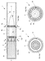
図1は、本発明の第1実施形態の飛翔体旋転システム1の説明図である。
図1(A)は縦断面図、図1(B)は図1(A)のA−A矢視図、図1(C)は図1(A)のB−B矢視図である。
(First embodiment)
FIG. 1 is an explanatory diagram of a flying object turning system 1 according to a first embodiment of the present invention.
1A is a longitudinal sectional view, FIG. 1B is a view taken along the line AA in FIG. 1A, and FIG. 1C is a view taken along the line BB in FIG.
本発明の飛翔体旋転システム1は、発射装置2、飛翔体8、及び回転装弾筒10を備える。また本発明の発射装置2は、砲身4と発射薬6とを有する。
The flying object turning system 1 of the present invention includes a
本発明の砲身4は、内周面4aが滑らかな円筒面に構成される。
発射薬6は、砲身4の砲腔内に、後方から燃焼ガス6a(図2を参照)を噴射する。それにより、飛翔体8の後方に位置する砲身4の砲腔(以下、後室R)のガス圧力が上昇し、飛翔体8を前方へ押し出す。
The gun barrel 4 of the present invention is configured as a cylindrical surface having a smooth inner
The propellant 6 injects
本発明の飛翔体8は、旋転しながら飛行する砲弾又はロケット弾である。飛翔体8は、砲身4の内周面4aから半径方向内方に隙間Qを隔てて砲身4に装填され、発射される。
また、飛翔体8は、回転装弾筒10を介して砲身4の内周面4aに回転可能に支持される。
The
Further, the
また本実施形態の回転装弾筒10は、飛翔体8に取り付けられ、回転装弾筒10の前後の砲腔を、互いに連通させながら仕切る。回転装弾筒10は、飛翔体8の後方から隙間Qを介して砲身4の外部へ流れる燃焼ガス6aを回転力に変換して、飛翔体8と共に回転する回転機構10aを有する。
回転装弾筒10は、例えば図1(C)に示すように、周方向の回転力を飛翔体8に伝達し、飛翔体8の表面に設けられた凹凸8bに着脱可能に噛み合う凹凸10bを有することが好ましい。
Moreover, the
For example, as shown in FIG. 1 (C), the
この凹凸8bにおける凹んだ部分の底面は、飛翔体8の凹凸8bではない部分の外周面8aより半径方向内方に位置することが好ましい。
それにより、凹んだ部分の底面と飛翔体8の凹凸8bではない部分の外周面8aとが成す段差に前部装弾筒14が引っ掛かるので、砲身内で飛翔体8に対して前部装弾筒14が前方に滑るのを防ぐことができる。
It is preferable that the bottom surface of the recessed portion of the
As a result, the
なお、回転装弾筒10から飛翔体8に回転力を伝達する機構は、その他の構成のものでもよい。
It should be noted that the mechanism for transmitting the rotational force from the
また、前部装弾筒14の前方の飛翔体8の外周面8aには、前部装弾筒14が飛翔体8の外周面8aに沿って前方へ移動しないように、図1(A)に示すようなストッパ8cが設けられていてもよい。それにより砲身内で前部装弾筒14が飛翔体8を後方に残して前方へ移動するのを防ぐことができる。
Further, the outer
図1の例では、回転装弾筒10は、飛翔体8の後端部に取り付けられる後部装弾筒12と、その前方(例えば飛翔体8の胴部)に取り付けられる前部装弾筒14とを有する。これらの回転装弾筒10は、砲身4の内周面4aに、回転可能に支持されている。例えば回転装弾筒10の外周面が、砲身4の内周面4aに沿った円筒面であり、砲身4の内周面4aに摺動かつ回転可能に支持されていてもよい。
In the example of FIG. 1, the
本実施形態の後部装弾筒12は、ラジアルタービン翼12bと、貫通孔12cとを有する。
The
ラジアルタービン翼12bは、飛翔体8の後端部に設けられた、飛翔体8の中心軸Z−Zを中心として回転する回転機構10aである。ラジアルタービン翼12bは、飛翔体8の後方(後室R)から貫通孔12cに向けて流れる燃焼ガス6aにより、飛翔体8と共に回転する。
The
貫通孔12cは、ラジアルタービン翼12bの半径方向外方に設けられ、回転装弾筒10の前後を連通させる孔である。例えば図1の例では、貫通孔12cは、後室Rと隙間Qとを連通させる。
The through
この構成により、発射薬6から燃焼ガス6aが発生することにより後室Rの圧力が高まり、飛翔体8の後端部を前方に押す。後室Rの圧力は、隙間Qの圧力より高いため、後室Rの燃焼ガス6aは、貫通孔12cに向けて流れる。ラジアルタービン翼12bを通り、貫通孔12cに向けて流れる燃焼ガス6aがラジアルタービン翼12bを回転させる。
With this configuration,
前部装弾筒14は、砲身4の内周面4aと飛翔体8の外周面8aとの間の隙間Qで外周面8a全周を取り囲む。そして燃焼ガス6aにより飛翔体8の中心軸Z−Zを中心として飛翔体8を回転させる。
The
前部装弾筒14の回転機構10aは、軸流タービン翼14aにより回転力が得られる。
軸流タービン翼14aは、隙間内で飛翔体8の外周面8aから半径方向外方に延び、周方向に間隔を隔ててその外周面8aに複数取り付けられる。軸流タービン翼14aは、後方から前方に向けて隙間Qを通る燃焼ガス6aにより、飛翔体8の中心軸Z−Zを中心として回転する回転力がかかる。そしてこの回転力により、前部装弾筒14の全体ごと、飛翔体8と共に、中心軸Z−Zを中心として回転する。
前部装弾筒14は、周方向に分割可能に設けられていることが好ましい。
The
The
The
本実施形態の回転装弾筒10の外周面は、砲身4の内周面4aに対して回転しながら前方へ滑るように、平滑な円筒面に設けられていることが好ましい。この場合、回転装弾筒10の外周面が砲身4の内周面4aに沿って、砲身内を回転しながら前方に滑る。
It is preferable that the outer peripheral surface of the
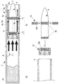
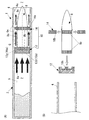
図2は、本発明の第1実施形態の飛翔体旋転システム1の作動を示す縦断面説明図である。
図2(A)は、発射薬6の起爆直後を示し、図2(B)は、砲身4から飛翔体8が放出された後を示す。
FIG. 2 is an explanatory longitudinal sectional view showing the operation of the flying object turning system 1 according to the first embodiment of the present invention.
2A shows immediately after the explosive of the propellant 6, and FIG. 2B shows after the flying
発射薬6が起爆し、燃焼ガス6aを放出すると、図2(A)に示すように、後室内のガス圧力が上昇し、隙間Qとの圧力差が大きくなる。それにより、飛翔体8の後端部に圧力がかかり、砲身内を飛翔体8が前方に向けて移動する。
When the propellant 6 explodes and releases the
また、この圧力差により、後室Rの燃焼ガス6aは、貫通孔12cに向けて流れる。この燃焼ガス6aの流れを受けてラジアルタービン翼12bが回転し、ラジアルタービン翼12bから回転力が飛翔体8に伝達されることで、飛翔体8が旋転する。
隙間Qへ流れた燃焼ガス6aは、隙間Qよりさらに圧力が低い砲身4の外部に向けて前方へ流れる。
Further, due to this pressure difference, the
The
それにより、隙間Qを前方に向けて流れる燃焼ガス6aにより、前部装弾筒14の軸流タービン翼14aは、中心軸Z−Zを中心として回転する。そして、軸流タービン翼14aの回転力が飛翔体8に伝達され、飛翔体8に、中心軸Z−Zを中心とする旋回力が与えられる。
Thereby, the
図2(B)に示すように、飛翔体8は、この回転力により回転しながら砲身4から放出される。砲身4から飛翔体8が飛び出すと、飛翔体8は、旋転しながら飛翔する。前部装弾筒14は、周方向に分割可能に設けられている。それにより、半径方向外方に向かう遠心力が前部装弾筒14にかかり、分割した前部装弾筒14が飛翔体8の半径方向外方へ移動し、飛翔体8から離脱する。
As shown in FIG. 2B, the flying
また飛翔体8の飛翔に伴い、後部装弾筒12の前面には後方に押す空気抵抗がかかる。後部装弾筒12は、この空気抵抗に後方へ押され、飛翔体8の後端部から後方に離脱する。
Further, as the flying
本実施形態の飛翔体旋転システム1は、これらの構成により、砲身4に腔線やガイドレールを設けなくても、飛翔体8を旋転させることができる。
The flying object rotation system 1 of this embodiment can rotate the flying
それにより、本発明の飛翔体旋転システム1は、砲身に腔線やガイドレールを設ける従来のシステムに比べ、砲身4を薄肉に製造でき、軽量化できる。また腔線やガイドレールを設けるのに必要な特殊な加工を必要としないので、本発明の飛翔体旋転システム1は、従来のシステムより発射装置2の製造費用を抑えられる。
Thereby, the flying object turning system 1 of the present invention can manufacture the gun barrel 4 to be thinner and lighter than the conventional system in which the cavity line and the guide rail are provided in the gun barrel. Further, since the special processing necessary for providing the cavity line and the guide rail is not required, the flying object turning system 1 of the present invention can reduce the manufacturing cost of the
また、回転装弾筒10の外周面が砲身4の内周面4aを周方向に滑るので、従来のシステムより、飛翔体8(回転装弾筒10)と砲身4の内周面4aとの間に生じる抵抗を小さくすることができる。それにより、後室内のガス圧力に対する速度損失を従来のシステムより少なくすることができる。
Further, since the outer peripheral surface of the
さらに、本発明の砲身4には腔線やガイドレールが設けられず、回転装弾筒10の外周面が砲身4の内周面4aに沿って滑りながら回転するので、砲身4に、飛翔体8の旋転の逆方向の回転力が発生するのを抑えることができる。
Further, the gun barrel 4 of the present invention is not provided with a cavity line or guide rails, and the outer peripheral surface of the
なお、本実施形態の飛翔体旋転システム1は、後部装弾筒12と前部装弾筒14の双方を備えるが、飛翔体8を回転させる機構として、後部装弾筒12と前部装弾筒14のいずれか一方のみを備えていてもよい。その場合、飛翔体旋転システム1は、砲身内に飛翔体8を回転可能に支持する装弾筒(以下、支持装弾筒)を備える。
Note that the flying object turning system 1 of the present embodiment includes both the
このとき、飛翔体旋転システム1が後部装弾筒12を備える場合は、支持装弾筒は、軸流タービン翼14aを有さない。
一方、飛翔体旋転システム1が前部装弾筒14のみを備える場合には、支持装弾筒は、前部装弾筒14と同様に軸流タービン翼14aを有していても有さなくてもよい。つまり、例えば飛翔体旋転システム1は、前後方向に間隔を隔てて複数の前部装弾筒14を備えていてもよい。
At this time, when the flying object turning system 1 includes the
On the other hand, when the flying object turning system 1 includes only the
(第2実施形態)
次に、本発明の第2実施形態の飛翔体旋転システム1について説明する。
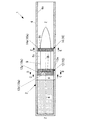
図3は、本発明の第2実施形態の飛翔体旋転システム1の縦断面図である。
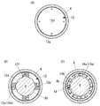
図4(A)は、図3のC−C矢視図である。図4(B)は図3のD−D矢視図、図4(C)は図3のE−E矢視図である。
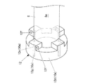
図5は、本発明の第2実施形態の後部装弾筒12の斜視図である。なお、図5においては、飛翔体8の外周面8aと回転装弾筒10の内周面に設けられる凹凸8b、10bの描写を省略している。
(Second Embodiment)
Next, the flying object turning system 1 according to the second embodiment of the present invention will be described.
FIG. 3 is a longitudinal sectional view of the flying object turning system 1 according to the second embodiment of the present invention.
4A is a view taken along the line CC in FIG. 4B is a view taken along the line DD in FIG. 3, and FIG. 4C is a view taken along the line EE in FIG.
FIG. 5 is a perspective view of the
本実施形態の前部装弾筒14は、第1実施形態のそれと同様である。
The
本実施形態の後部装弾筒12は、遮断壁12d、ノズル12e、及び長孔12gを有する。後部装弾筒12の回転機構10aは、遮断壁12d、ノズル12e、及び長孔12gである。
The
遮断壁12dは、砲身4の内周面4aに沿った滑らかな外周面を有する。この遮断壁12dの外周面が砲身4の内周面4aに沿って滑るようになっている。
また遮断壁12dは、砲腔を前後に遮断する。例えば遮断壁12dは、図3に示すように、飛翔体8の後端部に連結し、後室Rと隙間Qとの間に設けられていてもよい。この場合、遮断壁12dは、後室Rと隙間Qとの間を遮断する。しかしこれに限らず、遮断壁12dは、前部装弾筒14のように、飛翔体8の胴部上に、隙間Qの前後を遮断するように設けられていてもよい。
The blocking
Further, the blocking
長孔12gは、後端が遮断壁12dの後面に開口し、前方に延び、その前端がノズル12eに開口する。
The
ノズル12eは、長孔12gの前端部に連結し、遮断壁12dの前方で周方向の一方に向けて開口する。例えば図4、図5の例では、周方向に間隔を隔てて複数の突起が遮断壁12dから前方に向けて突出しており、その突起の周方向一方に、ノズル12eの開口12fが設けられている。
The
この構成により、本実施形態において、遮断壁12dの前後の砲腔は、長孔12gとノズル12eとを介して連通する。例えば図4、図5の例では、長孔12gとノズル12eによって、後室Rと隙間Qとが連通する。
With this configuration, in the present embodiment, the cannon cavities before and after the blocking
図6は、本発明の第2実施形態の飛翔体旋転システム1の作動を示す縦断面説明図である。
図6(A)は、発射薬6の起爆直後を示し、図6(B)は、砲身4から飛翔体8が放出された後を示す。
FIG. 6 is an explanatory longitudinal cross-sectional view showing the operation of the flying object turning system 1 according to the second embodiment of the present invention.
6A shows the state immediately after the explosive of the propellant 6, and FIG. 6B shows the state after the flying
図6(A)に示すように、発射装置2の発射薬6から燃焼ガス6aが放出されることによって、後室Rと隙間Qとの間の差圧が大きくなる。後室Rと隙間Qは、長孔12gとノズル12eのみで連通しているため、後室Rから長孔12gに流入する燃焼ガス6aは、ノズル12eの開口12fから周方向の一方に向けて隙間Qに噴射される。それにより、本実施形態の後部装弾筒12に回転力が加わり、後部装弾筒12が回転する。それにより、後部装弾筒12から飛翔体8に回転力が伝達され、飛翔体8が中心軸Z−Zを中心として旋転する。
As shown in FIG. 6 (A), when the
砲身4から飛翔体8が飛び出すと、飛翔体8は、旋転しながら飛翔する。それにより、半径方向外方に向かう遠心力が前部装弾筒14にかかり、前部装弾筒14が飛翔体8から離脱する。
When the flying
また飛翔体8の飛翔に伴い、後部装弾筒12の前面には後方に押す空気抵抗がかかる。それにより後部装弾筒12は、飛翔体8から後方に離脱する。
Further, as the flying
本実施形態の飛翔体旋転システム1は、後部装弾筒12に長孔12gとノズル12eを設けるという簡単な構成で成り立つので、飛翔体旋転システム1の製造費用をさらに抑えることができる。
The flying object turning system 1 according to the present embodiment has a simple configuration in which the
本実施形態の飛翔体旋転システム1のその他の構成と効果は、第1実施形態のそれと同様である。 Other configurations and effects of the flying object turning system 1 of the present embodiment are the same as those of the first embodiment.
上述した本発明の装置によれば、砲身4の内周面4aと飛翔体8と間に隙間Qがあり、その隙間Qを介して飛翔体8の後方から砲身4の外部へ燃焼ガス6aが流れる。その燃焼ガス6aの流れにより回転する回転機構10aを備え、回転機構10aが飛翔体8を回転させる。それにより、腔線やガイドレールを砲身4に設けなくても、飛翔体8を旋転させることができる。
According to the above-described apparatus of the present invention, there is a gap Q between the inner
したがって本発明の飛翔体旋転システム1は、腔線やガイドレールを砲身4に設ける必要が無いので、砲身4を薄肉に製造でき、軽量化を図ることができる。また腔線やガイドレールを設けるために、砲身4に特殊な加工を施す必要が無いため、従来のシステムより製造費用を抑えることができる。 Therefore, since the flying object turning system 1 of the present invention does not require the cavity line and the guide rail to be provided in the gun barrel 4, the gun barrel 4 can be manufactured thinly and the weight can be reduced. Further, since it is not necessary to specially process the gun barrel 4 in order to provide the cavity line and the guide rail, the manufacturing cost can be reduced as compared with the conventional system.
さらに、本発明の砲身4の内周面4aに腔線やガイドレールが無いことから、砲身4にかかる飛翔体8の旋転と逆方向の回転力を抑えることができる。
Furthermore, since there is no cavity line or guide rail on the inner
また砲身4の内周面4aが滑らかに設けられているので、従来のシステムより、飛翔体8が砲身内を移動する際に生じる抵抗が小さい。そのため、後室Rのガス圧力に対する飛翔体8の速度損失を従来のシステムより抑えることができる。そのため、従来のシステムより多くの後室Rの燃焼ガス6aのガス圧力を飛翔体8の速度に変換することができる。
Further, since the inner
なお本発明は上述した実施の形態に限定されず、本発明の要旨を逸脱しない範囲で種々変更を加え得ることは勿論である。 Note that the present invention is not limited to the above-described embodiment, and it is needless to say that various modifications can be made without departing from the gist of the present invention.
1 飛翔体旋転システム、2 発射装置、
4 砲身、4a 内周面、
6 発射薬、6a 燃焼ガス、
8 飛翔体、8a 外周面、8b 凹凸、8c ストッパ、
10 回転装弾筒、10a 回転機構、10b 凹凸、
12 後部装弾筒、12b ラジアルタービン翼、12c 貫通孔、
12d 遮断壁、12e ノズル、12f 開口、12g 長孔、
14 前部装弾筒、14a 軸流タービン翼、
R 後室、Q 隙間、Z−Z 中心軸
1 flying body rotation system, 2 launcher,
4 Gun barrel, 4a inner surface,
6 propellant, 6a combustion gas,
8 flying object, 8a outer peripheral surface, 8b unevenness, 8c stopper,
10 rotating bullet cylinder, 10a rotating mechanism, 10b unevenness,
12 rear shell, 12b radial turbine blade, 12c through hole,
12d blocking wall, 12e nozzle, 12f opening, 12g long hole,
14 front shell, 14a axial turbine blade,
R Rear chamber, Q clearance, ZZ center axis
Claims (6)
前記砲身の砲腔内に後方から燃焼ガスを噴射する発射薬と、
前記内周面から半径方向内方に隙間を隔てて前記砲身に装填される飛翔体と、
前記飛翔体に取り付けられ前記砲腔を前後に仕切る回転装弾筒と、を備え、
前記回転装弾筒は、その前後の前記砲腔を互いに連通させ、
前記飛翔体の後方から前記隙間を介して前記砲身の外部へ流れる前記燃焼ガスを回転力に変換して前記飛翔体と共に回転する回転機構を有する、飛翔体旋転システム。 A barrel with a smooth inner surface,
A propellant that injects combustion gas from behind into the barrel of the barrel,
A flying object loaded into the gun barrel with a gap radially inward from the inner peripheral surface;
A rotating bullet cylinder attached to the flying body and partitioning the cannon forward and backward,
The rotating bullet tube communicates the cannons before and after it,
A flying object turning system having a rotating mechanism that converts the combustion gas flowing from the rear of the flying object to the outside of the barrel through the gap into a rotational force and rotates together with the flying object.
前記軸流タービン翼は、前記隙間を通る前記燃焼ガスにより前記飛翔体の中心軸を中心として該飛翔体と共に回転する、請求項1に記載の飛翔体旋転システム。 The rotating mechanism has axial flow turbine blades that extend radially outward from the outer peripheral surface of the flying object within the gap and are attached to the outer peripheral surface at a plurality of intervals in the circumferential direction.
The flying body rotation system according to claim 1, wherein the axial-flow turbine blade rotates together with the flying body around the center axis of the flying body by the combustion gas passing through the gap.
前記回転装弾筒は、前記ラジアルタービン翼の半径方向外方に設けられ前記回転装弾筒の前後を連通させる貫通孔を有し、
前記ラジアルタービン翼は、前記飛翔体の後方から前記貫通孔に向けて流れる前記燃焼ガスにより前記飛翔体と共に回転する、請求項1に記載の飛翔体旋転システム。 The rotating mechanism is a radial turbine blade coaxial with the flying body provided at a rear end portion of the flying body,
The rotating bullet cylinder has a through-hole that is provided radially outward of the radial turbine blade and communicates the front and rear of the rotating bullet cylinder,
2. The flying body rotation system according to claim 1, wherein the radial turbine blade rotates together with the flying body by the combustion gas flowing from the rear of the flying body toward the through hole.
前記遮断壁の後面に開口し前方に延びる長孔と、
前記長孔の前端部に連結し前記遮断壁の前方で周方向の一方に向けて開口するノズルと、を有し、
前記回転装弾筒の前後の前記砲腔は、前記長孔と前記ノズルとを介して連通し、
さらに前記回転機構は、前記ノズルから周方向一方に噴射される前記燃焼ガスにより、前記飛翔体と共に回転する、請求項1に記載の飛翔体旋転システム。 The rotating mechanism has a smooth outer peripheral surface along the inner peripheral surface of the gun barrel and blocks the front and rear of the gun cavity,
An elongated hole that opens in the rear surface of the blocking wall and extends forward;
A nozzle that is connected to the front end of the elongated hole and opens toward one side in the circumferential direction in front of the blocking wall;
The cannons before and after the rotating bullet tube communicate with each other through the long hole and the nozzle,
Furthermore, the said rotating mechanism is a flying body rotation system of Claim 1 rotated with the said flying body by the said combustion gas injected in the circumferential direction one from the said nozzle.
Priority Applications (1)
| Application Number | Priority Date | Filing Date | Title |
|---|---|---|---|
| JP2016078788A JP6703883B2 (en) | 2016-04-11 | 2016-04-11 | Flying body rotation system |
Applications Claiming Priority (1)
| Application Number | Priority Date | Filing Date | Title |
|---|---|---|---|
| JP2016078788A JP6703883B2 (en) | 2016-04-11 | 2016-04-11 | Flying body rotation system |
Publications (2)
| Publication Number | Publication Date |
|---|---|
| JP2017190879A true JP2017190879A (en) | 2017-10-19 |
| JP6703883B2 JP6703883B2 (en) | 2020-06-03 |
Family
ID=60084646
Family Applications (1)
| Application Number | Title | Priority Date | Filing Date |
|---|---|---|---|
| JP2016078788A Active JP6703883B2 (en) | 2016-04-11 | 2016-04-11 | Flying body rotation system |
Country Status (1)
| Country | Link |
|---|---|
| JP (1) | JP6703883B2 (en) |
Cited By (3)
| Publication number | Priority date | Publication date | Assignee | Title |
|---|---|---|---|---|
| KR20200117279A (en) * | 2019-04-03 | 2020-10-14 | 국방과학연구소 | Rotational delivery test apparatus |
| CN115218730A (en) * | 2022-08-02 | 2022-10-21 | 昆明理工大学 | Guided ammunition |
| KR102908243B1 (en) * | 2024-07-08 | 2026-01-06 | 조성민 | Ballistic stabilization method using smoothbore guns |
-
2016
- 2016-04-11 JP JP2016078788A patent/JP6703883B2/en active Active
Cited By (4)
| Publication number | Priority date | Publication date | Assignee | Title |
|---|---|---|---|---|
| KR20200117279A (en) * | 2019-04-03 | 2020-10-14 | 국방과학연구소 | Rotational delivery test apparatus |
| KR102168079B1 (en) * | 2019-04-03 | 2020-10-20 | 국방과학연구소 | Rotational delivery test apparatus |
| CN115218730A (en) * | 2022-08-02 | 2022-10-21 | 昆明理工大学 | Guided ammunition |
| KR102908243B1 (en) * | 2024-07-08 | 2026-01-06 | 조성민 | Ballistic stabilization method using smoothbore guns |
Also Published As
| Publication number | Publication date |
|---|---|
| JP6703883B2 (en) | 2020-06-03 |
Similar Documents
| Publication | Publication Date | Title |
|---|---|---|
| US2426239A (en) | Rocket shell | |
| US3842741A (en) | Subprojectile launched from telescopic tubes | |
| JP6499649B2 (en) | Bullets for small or light weapons with projectile body | |
| KR102548318B1 (en) | single sealed projectile | |
| US4249465A (en) | Projectile | |
| KR102594186B1 (en) | Improved bullets, weapons provided with said bullets, kits for assembly thereof, and corresponding methods of manufacturing, operating and using the same | |
| JP6703883B2 (en) | Flying body rotation system | |
| US9593922B2 (en) | Fin deployment system | |
| US6085660A (en) | Low spin sabot | |
| US3098447A (en) | Projectiles to be slidably fitted on the end of a gun barrel | |
| US2798433A (en) | Stable sabot | |
| US2981188A (en) | Spin-stabilized projectile with nonrotating shaped charge | |
| US11248890B2 (en) | Enhanced ballistics and projectiles | |
| FI111296B (en) | Controlled subdivision holder for sub-caliber projectiles | |
| US10309755B1 (en) | Spin stabilized projectile for smoothbore barrels | |
| RU2482431C1 (en) | Cartridge for small arms and artillery smoothbore systems | |
| US10458768B1 (en) | Protection covering for folded tail fin of projectile | |
| TW202400958A (en) | Toy grenade and its projectile loading device | |
| WO2006091232A2 (en) | A finless training projectile with improved flight stability over an extended range | |
| RU2357198C1 (en) | Artillery shell | |
| RU2225974C1 (en) | Method imparting rotation to bullet or other projectile and firearm complex for its implementation | |
| US2927535A (en) | Finless hollow charge projectile | |
| US2793592A (en) | Reaction means for rotating ammunition projectiles at low speeds | |
| RU2534143C1 (en) | Cartridge for smooth-bore systems | |
| RU2810034C1 (en) | Casing of cluster warhead for rotating rocket projectile |
Legal Events
| Date | Code | Title | Description |
|---|---|---|---|
| A621 | Written request for application examination |
Free format text: JAPANESE INTERMEDIATE CODE: A621 Effective date: 20190218 |
|
| A977 | Report on retrieval |
Free format text: JAPANESE INTERMEDIATE CODE: A971007 Effective date: 20191205 |
|
| A131 | Notification of reasons for refusal |
Free format text: JAPANESE INTERMEDIATE CODE: A131 Effective date: 20200117 |
|
| A521 | Request for written amendment filed |
Free format text: JAPANESE INTERMEDIATE CODE: A523 Effective date: 20200311 |
|
| TRDD | Decision of grant or rejection written | ||
| A01 | Written decision to grant a patent or to grant a registration (utility model) |
Free format text: JAPANESE INTERMEDIATE CODE: A01 Effective date: 20200422 |
|
| A61 | First payment of annual fees (during grant procedure) |
Free format text: JAPANESE INTERMEDIATE CODE: A61 Effective date: 20200511 |
|
| R150 | Certificate of patent or registration of utility model |
Ref document number: 6703883 Country of ref document: JP Free format text: JAPANESE INTERMEDIATE CODE: R150 |
|
| R250 | Receipt of annual fees |
Free format text: JAPANESE INTERMEDIATE CODE: R250 |
|
| R250 | Receipt of annual fees |
Free format text: JAPANESE INTERMEDIATE CODE: R250 |
|
| S531 | Written request for registration of change of domicile |
Free format text: JAPANESE INTERMEDIATE CODE: R313531 |
|
| R250 | Receipt of annual fees |
Free format text: JAPANESE INTERMEDIATE CODE: R250 |
|
| R350 | Written notification of registration of transfer |
Free format text: JAPANESE INTERMEDIATE CODE: R350 |
|
| R250 | Receipt of annual fees |
Free format text: JAPANESE INTERMEDIATE CODE: R250 |