JP2017190876A - Ceramic member for heat exchanger - Google Patents
Ceramic member for heat exchanger Download PDFInfo
- Publication number
- JP2017190876A JP2017190876A JP2016078580A JP2016078580A JP2017190876A JP 2017190876 A JP2017190876 A JP 2017190876A JP 2016078580 A JP2016078580 A JP 2016078580A JP 2016078580 A JP2016078580 A JP 2016078580A JP 2017190876 A JP2017190876 A JP 2017190876A
- Authority
- JP
- Japan
- Prior art keywords
- flow path
- ceramic member
- cross
- heat exchanger
- view
- Prior art date
- Legal status (The legal status is an assumption and is not a legal conclusion. Google has not performed a legal analysis and makes no representation as to the accuracy of the status listed.)
- Pending
Links
Images

Landscapes
- Heat-Exchange Devices With Radiators And Conduit Assemblies (AREA)
Abstract
【課題】圧力損失の増加を抑制させつつ、熱交換効率に優れた熱交換器用セラミックス部材を提供する。【解決手段】本発明にかかる熱交換器用セラミックス部材1にあっては、流体が流通する第1流路2と、前記第1流路2と平面視上交差または平行に形成され、かつ側面視上離間した、流体が流通する第2流路3と、を備え、前記第1流路2若しくは第2流路3の少なくとも一の流路の断面が矩形形状または楕円形状に形成されている。この熱交換器用セラミックス部材では、第1流路と第2流路のうち少なくとも一の流路の断面が矩形形状または楕円形状に形成されているため、圧力損失の増加を抑制させつつ、流路数及び熱交換面積を増加させることができ、優れた熱交換効率を得ることができる。【選択図】図1[Problem] To provide a ceramic member for a heat exchanger that has excellent heat exchange efficiency while suppressing an increase in pressure loss. [Solution] The ceramic member for a heat exchanger (1) according to the present invention comprises a first flow path (2) through which a fluid flows, and a second flow path (3) through which a fluid flows that is formed intersecting or parallel to the first flow path (2) in a plan view and spaced apart in a side view, and at least one of the first flow path (2) or the second flow path (3) has a rectangular or elliptical cross section. In this ceramic member for a heat exchanger, because at least one of the first flow path and the second flow path has a rectangular or elliptical cross section, it is possible to increase the number of flow paths and the heat exchange area while suppressing an increase in pressure loss, thereby achieving excellent heat exchange efficiency. [Selected Figure] Figure 1
Description
本発明は、熱交換用セラミックス部材に関する。 The present invention relates to a ceramic member for heat exchange.
従来から、特許文献1,2に示すように、熱交換器用部材として立方体状体や円柱状等のブロック体状のセラミックス部材が知られている。
このブロック体状のセラミックス部材10は、例えば、図6に示すように、側面1Cから対向面(側面)1Eに向けて延設された第1の流路4と、前記側面1Cと異なる側面1Dから対向面(側面)1Fに向けて、前記第1の流路4の間を通るように延設された第2の流路5とを備えている。
また、前記第1の流路4、前記第2の流路5はドリル等の穿孔手段によって形成される。そのため、前記第1の流路4、前記第2の流路5の断面形状は円形状に形成されている。
そして、このように構成された前記第1の流路4に媒体を流通させると共に、第2の流路5に冷媒または熱媒体を流通させることより、前記セラミックス部材10を介して熱交換が行われる。
Conventionally, as shown in
For example, as shown in FIG. 6, the block-shaped
The
Then, the medium is circulated through the
ところで、前記したように、第1流路、前記第2流路の断面形状は、等方的な円形状であるため、前記第1流路、前記第2流路をセラミックス部材の一面内に密に配置することができず、熱交換効率の更なる向上を図ることができないという技術的課題があった。
この課題を解決するために、第1流路、前記第2流路の直径(内径)を小さくすること(微細な流路にすること)により、流路数を増やし、熱交換効率の向上を図ることが考えられる。しかしながら、第1流路、前記第2流路の直径(内径)を小さくすることは、圧力損失が増大するという新たな技術的課題を招来するものである。
Incidentally, as described above, since the cross-sectional shapes of the first flow path and the second flow path are isotropic circular shapes, the first flow path and the second flow path are within one surface of the ceramic member. There is a technical problem that the heat exchange efficiency cannot be further improved because the heat exchanger cannot be arranged densely.
In order to solve this problem, by reducing the diameter (inner diameter) of the first flow path and the second flow path (by making the flow path fine), the number of flow paths can be increased and the heat exchange efficiency can be improved. It is possible to plan. However, reducing the diameter (inner diameter) of the first flow path and the second flow path brings about a new technical problem that pressure loss increases.
本発明は、上記技術的課題を解決するためになされたものであり、圧力損失の増加を抑制させつつ、熱交換効率に優れた熱交換器用セラミックス部材を提供することを目的とする。 The present invention has been made to solve the above technical problem, and an object thereof is to provide a ceramic member for a heat exchanger that is excellent in heat exchange efficiency while suppressing an increase in pressure loss.
上記目的を達成するためになされた本発明にかかる熱交換器用セラミックス部材は、流体が流通する第1流路と、前記第1流路と平面視上交差または平行に形成され、かつ側面視上離間した、流体が流通する第2流路と、を備え、前記第1流路と第2流路のうち少なくとも一の流路の断面が矩形形状または楕円形状であることを特徴としている。 The ceramic member for a heat exchanger according to the present invention, which has been made to achieve the above object, is formed in a first flow path through which a fluid flows, in parallel with or parallel to the first flow path, and in a side view. And a second flow path through which a fluid flows. The cross section of at least one of the first flow path and the second flow path is rectangular or elliptical.
このように、本発明にかかる熱交換器用セラミックス部材では、第1流路と第2流路のうち少なくとも一の流路の断面が矩形形状または楕円形状に形成されているため、圧力損失の増加を抑制させつつ、流路数及び熱交換面積を増加させることができ、優れた熱交換効率を得ることができる。
尚、矩形形状は一般にすべての角が直角の四辺形を意味するが、ここでは角部が直角の形状ものに限定されない。また、角部は面取り加工、アール(曲面)加工あるいはフルアール加工を施していても良い。
As described above, in the ceramic member for a heat exchanger according to the present invention, the cross section of at least one of the first flow path and the second flow path is formed in a rectangular shape or an elliptical shape. It is possible to increase the number of flow paths and the heat exchange area while suppressing the above, and to obtain excellent heat exchange efficiency.
The rectangular shape generally means a quadrilateral whose right angles are right angles, but is not limited to a right angle shape here. The corner may be chamfered, rounded (curved surface) or full rounded.
ここで、前記第2流路と前記第1流路とが、互いに平面視上直交し、かつ側面視上離間していることが望ましい。
また、前記一の流路の断面における矩形形状または楕円形状の短径が、3.2mm以上であって、前記一の流路の断面における矩形形状または楕円形状の短径に対する前記長径の比が1.2以上10以下であることが望ましい。
Here, it is desirable that the second flow path and the first flow path are orthogonal to each other in plan view and separated from each other in side view.
In addition, the short axis of the rectangular shape or the elliptical shape in the cross section of the one flow path is 3.2 mm or more, and the ratio of the long diameter to the short diameter of the rectangular shape or the elliptical shape in the cross section of the one flow path is It is desirable that it is 1.2 or more and 10 or less.
本発明によれば、圧力損失の増加を抑制させつつ、熱交換効率に優れた熱交換器用セラミックス部材を得ることができる。 ADVANTAGE OF THE INVENTION According to this invention, the ceramic member for heat exchangers excellent in heat exchange efficiency can be obtained, suppressing the increase in pressure loss.
以下、本発明にかかる熱交換器用セラミックス部材の一実施形態を、図1乃至図6に基づいて説明する。
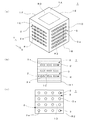
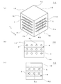
図1に示すように、本願にかかる熱交換器用セラミックス部材(以下、セラミックス部材という)1は、セラミックス材料で形成された直方体形状のブロック体である。このセラミックス部材1の形状は、前記直方体形状に限定されるものではなく、円柱形状、立方体形状であっても良い。また、セラミックス部材1の材質としては、例えば炭化ケイ素、アルミナ、窒化ケイ素、窒化アルミニウム、マグネシア、グラファイトを用いるのが好ましい。さらに、セラミックス部材1の材質は、炭化ケイ素、アルミナであることがさらに好ましい。特に、熱伝導率が高く耐薬品性に優れた炭化ケイ素が好ましく、中でも常圧焼結炭化ケイ素がより好ましい。
Hereinafter, an embodiment of a ceramic member for a heat exchanger according to the present invention will be described with reference to FIGS. 1 to 6.
As shown in FIG. 1, a ceramic member for heat exchanger (hereinafter referred to as a ceramic member) 1 according to the present application is a rectangular parallelepiped block body formed of a ceramic material. The shape of the
前記したように、セラミックス部材1は直方体形状のブロック体であり、上面1Aと、前記上面1Aの対向面である底面1Bと、前記上面1Aと前記底面1Bの間に垂直に設置された4つの側面1C,1D,1E,1Fにより構成されている。
尚、前記側面1Cと前記側面1Eは相対向する面であり、前記側面1Dと前記側面1Fは相対向する面である。
As described above, the
The side surface 1C and the side surface 1E are opposite surfaces, and the side surface 1D and the side surface 1F are opposite surfaces.
前記セラミックス部材1は、図1及び図2に示すように、媒体である流体が流通する第1流路2が形成されている。
この第1流路2は複数の流路からなり、セラミックス部材1の側面1Cからその対向面(側面)1Eに直線状に延設され、夫々の側面1C,1Eにおいて開口部2aが形成されている。
As shown in FIGS. 1 and 2, the
The
また、前記セラミックス部材1は、図1及び図2に示すように、媒体である流体が流通する第2流路3が形成されている。
この第2流路3は複数の流路からなり、セラミックス部材1の側面1Dからその対向面1Fに直線状に延設され、夫々の側面1D、1Fにおいて開口部3aが形成されている。
Moreover, as shown in FIGS. 1 and 2, the
The
前記第1流路2と前記第2流路3は、図2に示すように平面視上直交して形成されている。また、図1(b)(c)に示すように、前記第1流路2と前記第2流路3は、側面視上離間している。即ち、前記第1流路2と第2流路3は互いに交わることなく配置されている。
尚、図3(a)に示しように、前記第1流路2と第2流路3とが、平面視上交差するように配置しても良い。また図3(b)に示すように、前記第1流路2と第2流路3とが、平面視上平行に配置しても良く、この場合、前記第1流路2の開口部2aが形成された面と同一の面に、第2流路3の開口部3aが形成される。
The
In addition, as shown to Fig.3 (a), you may arrange | position so that the said
更に、第1流路2の断面形状について図1、図4、図5に基づいて説明する。
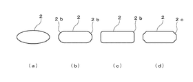
この第1流路2の断面は、第2流路3の円形の断面形状とは異なり、図1に示すように矩形形状に形成されている。尚、第1流路2の断面は、矩形形状に限定されるものではなく、図4(a)に示すように、楕円形状であっても良い。
このように、第1流路2の断面の形状が、矩形形状または楕円形状になすことにより、第1流路2を密に配置することができ、流路数及び熱交換面積(流路表面積)を増加させることができる。
Furthermore, the cross-sectional shape of the
Unlike the circular cross-sectional shape of the
Thus, when the cross-sectional shape of the
前記矩形形状は,一般にすべての角が直角の四辺形を意味するが、ここでは角部が直角の形状ものに限定されず、図4(c)に示すように、前記矩形形状の流路の角部をアール形状の角部2b、図4(d)に示すように面取り部2c、あるいは図4(b)に示すようにフルアール(半円状のアール)2dとしたものであっても良い。 The rectangular shape generally means a quadrilateral whose right angles are right angles, but is not limited to a right angle shape here, and as shown in FIG. The corner may be a rounded corner 2b, a chamfer 2c as shown in FIG. 4 (d), or a full round (semicircular round) 2d as shown in FIG. 4 (b). .
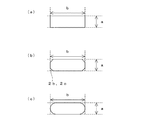
更に図5(a)に示すように、前記第1流路2の断面は、前記第1流路2の断面形状の短径aが3.2mm以上に、かつ前記第1流路2の断面形状の短径aに対する前記長径bの比が1.2以上、10以下になるように形成されている。
前記第1流路2の断面形状の短径aが3.2mm未満の場合には、圧力損失が大きくなるため好ましくない。なお、短径aの上限は特に限定されないが、流路を高密度で配置することができるため、30mm以下が好ましい。
Further, as shown in FIG. 5A, the cross section of the
If the minor axis “a” of the cross-sectional shape of the
また、前記第1流路2の断面形状の短径aに対する前記長径bの比が1.2未満の場合には第2流路を高密度に配置できなくなるため圧力損失が大きく、また前記第1流路2の断面形状の短径aに対する前記長径bの比が10を超える場合には、第1流路を高密度に配置することができないため、好ましくない。
したがって、前記第1流路2の断面形状の短径aが3.2mm以上に、かつ前記第1流路2の断面形状の短径aに対する前記長径bの比が1.2以上10以下である場合には、圧力損失が少なく、従来のセラミックス部材よりも高密度に流路を配置することができ、熱交換効率の向上を図ることができる。
尚、長径、短径とは、矩形形状の場合には幅、高さをいう。また図5(b)に示すように、角部をアール形状角部2b、面取り部2cとした場合、図5(c)に示すようにフルアール(半円状のアール)2dとした場合には、長径を示す辺と短径を示す辺を延長した交点から交点までの距離をもって、長径、短径の長さとする。
隣り合う断面形状の距離(ピッチ)は、1.5mm以上10mm以下であることが好ましい。この範囲であることにより、流路を高密度で配置することができるため好ましい。
Further, when the ratio of the major axis b to the minor axis a of the cross-sectional shape of the
Therefore, the minor axis a of the cross-sectional shape of the
The major axis and minor axis refer to the width and height in the case of a rectangular shape. As shown in FIG. 5 (b), when the corners are round-shaped corners 2b and chamfered portions 2c, as shown in FIG. 5 (c), when the full-round (semicircular round) 2d is used. The distance from the intersection where the side indicating the major axis and the side indicating the minor axis are extended to the intersection is defined as the length of the major axis and minor axis.
The distance (pitch) between adjacent cross-sectional shapes is preferably 1.5 mm or more and 10 mm or less. This range is preferable because the channels can be arranged with high density.
上記実施形態にあっては、前記第1流路の断面形状が矩形形状等に形成する場合について説明したが、本発明はこれに限定されるものではなく、前記第2流路の断面形状を矩形形状等に形成しても良く、また前記第1、第2流路の断面形状を矩形形状等に形成しても良い。 In the above embodiment, the case where the cross-sectional shape of the first flow path is formed in a rectangular shape or the like has been described, but the present invention is not limited to this, and the cross-sectional shape of the second flow path is the same. It may be formed in a rectangular shape or the like, and the cross-sectional shape of the first and second flow paths may be formed in a rectangular shape or the like.
また、本願に係る熱交換器用セラミックス部材は、公知の手法によって製造することができる。好ましくは鋳込み成形により矩形形状の流路を形成する。例えば、流路断面形状を有する棒状部材を所定の位置に配置した型内に、セラミックス部材の泥漿を流し込み、固化後に前記棒状部材を取り除くことにより成形し、乾燥後、必要であれば成形体加工をおこない、焼成することにより得ることができる。 Moreover, the ceramic member for heat exchangers according to the present application can be manufactured by a known method. Preferably, the rectangular flow path is formed by casting. For example, a rod-shaped member having a channel cross-sectional shape is placed in a predetermined position, a ceramic member slurry is poured into the mold, the solid-shaped member is removed after solidification, and after drying, if necessary, a molded body is processed. It can obtain by performing and baking.
以下、本発明を実施例に基づきさらに具体的に説明をするが、本発明は下記の実施例により制限されるものではない。 Hereinafter, the present invention will be described more specifically based on examples, but the present invention is not limited to the following examples.
(実施例1)
100mm×100mm×100mmの立方体からなるセラミックス部材1を用いて行った。
セラミックス部材の側面1Cから対向する側面1E方向へ延びる第1流路を形成した。この第1流路は、矩形形状の断面形状を有し、短径aは断面の底面から垂直方向に4mmとし、長径bは断面の底面から水平方向に13mmとした。第1流路の間隔は水平方向に 1.8mm、垂直方向に10.1mmとし、合計25本の第1流路を設けた。
Example 1
This was performed using a
The 1st flow path extended in the direction of the side surface 1E which opposes from the side surface 1C of a ceramic member was formed. The first flow path has a rectangular cross-sectional shape, the short diameter a is 4 mm in the vertical direction from the bottom surface of the cross section, and the long diameter b is 13 mm in the horizontal direction from the bottom surface of the cross section. The interval between the first flow paths was 1.8 mm in the horizontal direction and 10.1 mm in the vertical direction, and a total of 25 first flow paths were provided.
つぎに、側面1Dから対向する側面1F方向へ延びる第2流路を形成した。
この第2流路は、円形形状の断面形状を有し、内径は6.5mmとした。
第2流路の間隔は水平方向に1.8mm、垂直方向に7.6mmとし、合計54本の第2流路を設けた。
Next, the 2nd flow path extended in the side surface 1F direction which opposes from the side surface 1D was formed.
The second flow path has a circular cross-sectional shape and an inner diameter of 6.5 mm.
The interval between the second flow paths was 1.8 mm in the horizontal direction and 7.6 mm in the vertical direction, and a total of 54 second flow paths were provided.
そして、側面1C側から、95℃の温水を0.5ton/hで第1流路に導入した。一方、側面1D側から、20℃の冷水を0.5ton/hで第2流路に導入した。 And 95 degreeC warm water was introduce | transduced into the 1st flow path at 0.5 ton / h from the side surface 1C side. On the other hand, cold water of 20 ° C. was introduced into the second channel at 0.5 ton / h from the side surface 1D side.
(実施例2)
100mm×100mm×100mmの立方体からなるセラミックス部材1を用いて行った。
セラミックス部材の側面1Cから対向する側面1E方向へ延びる第1流路を形成した。この第1流路は、楕円形状の断面形状を有し、短径aは断面の底面から垂直方向に4mmとし、長径bは断面の底面から水平方向に13mmとした。第1流路の間隔は水平方向に 1.8mm、垂直方向に10.1mmとし、合計25本の第1流路を設けた。
(Example 2)
This was performed using a
The 1st flow path extended in the direction of the side surface 1E which opposes from the side surface 1C of a ceramic member was formed. The first flow path has an elliptical cross-sectional shape, the short diameter a is 4 mm in the vertical direction from the bottom surface of the cross section, and the long diameter b is 13 mm in the horizontal direction from the bottom surface of the cross section. The interval between the first flow paths was 1.8 mm in the horizontal direction and 10.1 mm in the vertical direction, and a total of 25 first flow paths were provided.
つぎに、側面1Dから対向する側面1F方向へ延びる第2流路を形成した。
この第2流路は、円形形状の断面形状を有し、内径は6.5mmとした。
第2流路の間隔は水平方向に1.8mm、垂直方向に7.6mmとし、合計54本の第2流路を設けた。
Next, the 2nd flow path extended in the side surface 1F direction which opposes from the side surface 1D was formed.
The second flow path has a circular cross-sectional shape and an inner diameter of 6.5 mm.
The interval between the second flow paths was 1.8 mm in the horizontal direction and 7.6 mm in the vertical direction, and a total of 54 second flow paths were provided.
そして、側面1C側から、95℃の温水を0.5ton/hで第1流路に導入した。一方、側面1D側から、20℃の冷水を0.5ton/hで第2流路に導入した。 And 95 degreeC warm water was introduce | transduced into the 1st flow path at 0.5 ton / h from the side surface 1C side. On the other hand, cold water of 20 ° C. was introduced into the second channel at 0.5 ton / h from the side surface 1D side.
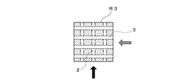
比較例として用いたセラミックス部材を図7に示す。第1流路の断面形状及びその設置間隔以外は、実施例と同様である。 A ceramic member used as a comparative example is shown in FIG. Except for the cross-sectional shape of the first flow path and the installation interval, it is the same as the embodiment.
比較例の側面1Cから対向する側面1E方向へ延びる、内径φ6.5mmの円形形状の断面形状を有する第1流路を形成した。また、第1流路の間隔は水平方向に1.8mm、垂直方向に10.1mmとし、合計45本の第1流路を設けた。
つぎに、側面1Dから対向する側面1F方向へ延びる第2流路を形成した。
この第2流路の断面形状は円形形状であり、内径は6.5mmとした。第2流路の間隔は水平方向に1.8mm、垂直方向に10.1mmとし、合計36本の第2流路を設けた。
A first flow path having a circular cross-sectional shape having an inner diameter of 6.5 mm and extending from the side surface 1C of the comparative example in the direction of the side surface 1E opposed thereto was formed. The interval between the first flow paths was 1.8 mm in the horizontal direction and 10.1 mm in the vertical direction, and a total of 45 first flow paths were provided.
Next, the 2nd flow path extended in the side surface 1F direction which opposes from the side surface 1D was formed.
The cross-sectional shape of the second flow path was a circular shape, and the inner diameter was 6.5 mm. The interval between the second flow paths was 1.8 mm in the horizontal direction and 10.1 mm in the vertical direction, and a total of 36 second flow paths were provided.
そして、実施例と同様に側面1Cから、95℃の温水を0.5ton/hで第1流路に導入した。また、側面1Dから、20℃の冷水を0.5ton/hで第2流路に導入した。 And 95 degreeC warm water was introduce | transduced into the 1st flow path at 0.5 ton / h from the side surface 1C similarly to the Example. Moreover, 20 degreeC cold water was introduce | transduced into the 2nd flow path at 0.5 ton / h from side surface 1D.
実施例及び比較例の結果を表1、表2に示す。
表1、表2中の導入温度とは、側面1C、側面1Dにおける流路開口部における温度であり、流出温度とは側面1E、側面1Fにおける流路開口部における温度である。温度差は前記導入温度と流出温度の差を示したものである。また、圧力損失とは、第1、第2流路内の圧力損失を示す。
The results of Examples and Comparative Examples are shown in Tables 1 and 2.
The introduction temperature in Tables 1 and 2 is the temperature at the channel opening at the side surface 1C and side surface 1D, and the outflow temperature is the temperature at the channel opening at the side surface 1E and side surface 1F. The temperature difference indicates the difference between the introduction temperature and the outflow temperature. The pressure loss indicates the pressure loss in the first and second flow paths.
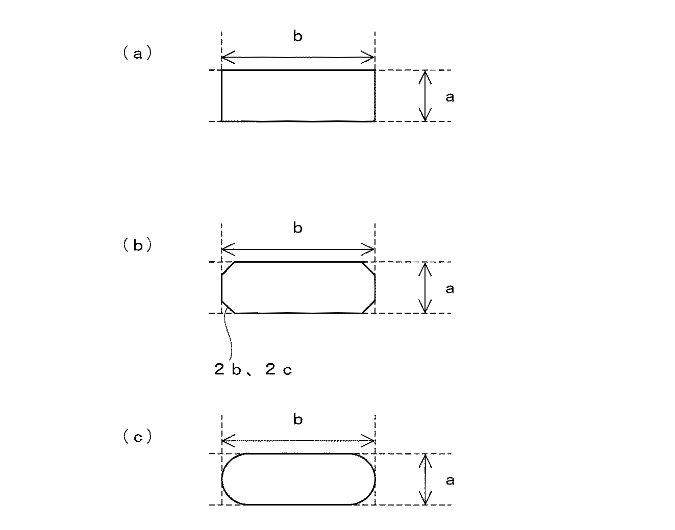
表1、表2に示す結果より、実施例1の熱交換の結果は22.5℃の温度差を生じた。一方、比較例の温度差は約20℃であった。このことから、実施例1では、約13%の熱交換効率の向上が確認された。 From the results shown in Tables 1 and 2, the heat exchange result of Example 1 produced a temperature difference of 22.5 ° C. On the other hand, the temperature difference of the comparative example was about 20 ° C. From this, in Example 1, the improvement of the heat exchange efficiency of about 13% was confirmed.
また、実施例1の第1流路の圧力損失は0.99Paであり、比較例の第1流路の圧力損失は0.74Paであり、大きな差異は認められなかった。
一方、実施例1の第2流路の圧力損失は1.16Paであり、比較例の第1流路の圧力損失は1.85Paであり、第1流路を発明のような矩形形状にしたことにより第2流路の本数を増やすことができたため圧力損失を小さくすることができた。
Moreover, the pressure loss of the 1st flow path of Example 1 was 0.99 Pa, the pressure loss of the 1st flow path of the comparative example was 0.74 Pa, and the big difference was not recognized.
On the other hand, the pressure loss of the second flow path of Example 1 is 1.16 Pa, the pressure loss of the first flow path of the comparative example is 1.85 Pa, and the first flow path has a rectangular shape as in the invention. As a result, the number of second flow paths could be increased, and the pressure loss could be reduced.
1 熱交換器用セラミックス部材
1A 上面
1B 底面
1C 側面
1D 側面
1E 側面
1F 側面
2 第1流路
3 第2流路
DESCRIPTION OF
Claims (3)
前記第1流路と平面視上交差または平行に形成され、かつ側面視上離間した、流体が流通する第2流路と、
を備え、
前記第1流路と第2流路のうち少なくとも一の流路の断面が矩形形状または楕円形状であることを特徴とする熱交換器用セラミックス部材。 A first flow path through which fluid flows;
A second flow path through which a fluid flows, which is formed to intersect or be parallel to the first flow path in plan view and spaced apart in side view;
With
A ceramic member for a heat exchanger, wherein a cross section of at least one of the first flow path and the second flow path is rectangular or elliptical.
前記一の流路の断面における矩形形状または楕円形状の短径に対する前記長径の比が、1.2以上10以下であることを特徴とする請求項1または請求項2に記載の熱交換用セラミックス部材。 The short axis of the rectangular or elliptical shape in the cross section of the one channel is 3.2 mm or more,
3. The ceramic for heat exchange according to claim 1, wherein a ratio of the major axis to a minor axis of a rectangular shape or an elliptical shape in a cross section of the one flow path is 1.2 or more and 10 or less. Element.
Priority Applications (1)
| Application Number | Priority Date | Filing Date | Title |
|---|---|---|---|
| JP2016078580A JP2017190876A (en) | 2016-04-11 | 2016-04-11 | Ceramic member for heat exchanger |
Applications Claiming Priority (1)
| Application Number | Priority Date | Filing Date | Title |
|---|---|---|---|
| JP2016078580A JP2017190876A (en) | 2016-04-11 | 2016-04-11 | Ceramic member for heat exchanger |
Publications (1)
| Publication Number | Publication Date |
|---|---|
| JP2017190876A true JP2017190876A (en) | 2017-10-19 |
Family
ID=60086315
Family Applications (1)
| Application Number | Title | Priority Date | Filing Date |
|---|---|---|---|
| JP2016078580A Pending JP2017190876A (en) | 2016-04-11 | 2016-04-11 | Ceramic member for heat exchanger |
Country Status (1)
| Country | Link |
|---|---|
| JP (1) | JP2017190876A (en) |
Cited By (1)
| Publication number | Priority date | Publication date | Assignee | Title |
|---|---|---|---|---|
| CN115135952A (en) * | 2020-02-27 | 2022-09-30 | 三菱重工业株式会社 | Heat exchange core and heat exchanger |
Citations (6)
| Publication number | Priority date | Publication date | Assignee | Title |
|---|---|---|---|---|
| US4298059A (en) * | 1978-09-23 | 1981-11-03 | Rosenthal Technik Ag | Heat exchanger and process for its manufacture |
| JPS59186621A (en) * | 1983-04-05 | 1984-10-23 | Ngk Insulators Ltd | Porous body |
| JPS6066098A (en) * | 1983-09-19 | 1985-04-16 | ジ−・テイ−・イ−・プロダクツ・コ−ポレイシヨン | Dc-ac type heat exchanger made of ceramic |
| JPS60142199A (en) * | 1983-12-29 | 1985-07-27 | Kurosaki Refract Co Ltd | Heat exchanger unit made of ceramic |
| JPS6183897A (en) * | 1984-09-28 | 1986-04-28 | Asahi Glass Co Ltd | Ceramic heat exchanging unit |
| JPH08261679A (en) * | 1995-03-28 | 1996-10-11 | Ngk Insulators Ltd | Multitubular heat exchanger and manufacture thereof |
-
2016
- 2016-04-11 JP JP2016078580A patent/JP2017190876A/en active Pending
Patent Citations (7)
| Publication number | Priority date | Publication date | Assignee | Title |
|---|---|---|---|---|
| US4298059A (en) * | 1978-09-23 | 1981-11-03 | Rosenthal Technik Ag | Heat exchanger and process for its manufacture |
| JPS59186621A (en) * | 1983-04-05 | 1984-10-23 | Ngk Insulators Ltd | Porous body |
| JPS6066098A (en) * | 1983-09-19 | 1985-04-16 | ジ−・テイ−・イ−・プロダクツ・コ−ポレイシヨン | Dc-ac type heat exchanger made of ceramic |
| US4776387A (en) * | 1983-09-19 | 1988-10-11 | Gte Products Corporation | Heat recuperator with cross-flow ceramic core |
| JPS60142199A (en) * | 1983-12-29 | 1985-07-27 | Kurosaki Refract Co Ltd | Heat exchanger unit made of ceramic |
| JPS6183897A (en) * | 1984-09-28 | 1986-04-28 | Asahi Glass Co Ltd | Ceramic heat exchanging unit |
| JPH08261679A (en) * | 1995-03-28 | 1996-10-11 | Ngk Insulators Ltd | Multitubular heat exchanger and manufacture thereof |
Cited By (1)
| Publication number | Priority date | Publication date | Assignee | Title |
|---|---|---|---|---|
| CN115135952A (en) * | 2020-02-27 | 2022-09-30 | 三菱重工业株式会社 | Heat exchange core and heat exchanger |
Similar Documents
| Publication | Publication Date | Title |
|---|---|---|
| KR101803281B1 (en) | A plate heat exchanger | |
| JP5884055B2 (en) | Heat exchanger and offset fin for heat exchanger | |
| US20080179046A1 (en) | Water cooling apparatus | |
| US10077947B2 (en) | Cooling assembly and method for manufacturing the same | |
| US20120048524A1 (en) | Ceramic heat exchanger and method of producing same | |
| CN104215103B (en) | Pottery heat exchanger plates and the ceramic heat exchange core body assembled by it | |
| CN205213228U (en) | Radiator bottom plate and have its radiator and IGBT module | |
| JP2017507312A (en) | Heat exchange plate for plate heat exchanger and plate heat exchanger provided with said heat exchange plate | |
| JP2011052909A (en) | Kiln tool plate for ceramic firing | |
| JP4013883B2 (en) | Heat exchanger | |
| JP2017190876A (en) | Ceramic member for heat exchanger | |
| JPWO2018181981A1 (en) | Tubular sapphire member, heat exchanger, semiconductor manufacturing apparatus, and method for manufacturing tubular sapphire member | |
| JP6421781B2 (en) | Heat exchanger | |
| KR101218314B1 (en) | Micro Channel Plate for Heat Exchanger | |
| CN201867109U (en) | Improved structure of flat heat pipe with composite capillary tissue | |
| CN114649280A (en) | Micro-channel radiator with gill bionic structure | |
| CN103298322A (en) | Heat exchange surface structure with reinforced heat convection capability | |
| KR101743318B1 (en) | Manufacturing method of heat insulation wall body and heat insulation wall body | |
| CN102089074A (en) | Packing element for heat and mass transfer towers | |
| CN204255151U (en) | The ceramic heat exchange core body structure of pottery heat exchanger plates assembling | |
| EP3023727B1 (en) | Fluid guide plate and associated plate heat exchanger | |
| CN110537070A (en) | Plate heat exchanger | |
| CN212658108U (en) | A heat storage body and a heat storage integral structure | |
| JP2007294983A (en) | Heat exchanger | |
| CN204202450U (en) | A kind of ceramic heat exchange core body |
Legal Events
| Date | Code | Title | Description |
|---|---|---|---|
| A621 | Written request for application examination |
Free format text: JAPANESE INTERMEDIATE CODE: A621 Effective date: 20180608 |
|
| A977 | Report on retrieval |
Free format text: JAPANESE INTERMEDIATE CODE: A971007 Effective date: 20190327 |
|
| A131 | Notification of reasons for refusal |
Free format text: JAPANESE INTERMEDIATE CODE: A131 Effective date: 20190510 |
|
| A521 | Request for written amendment filed |
Free format text: JAPANESE INTERMEDIATE CODE: A523 Effective date: 20190709 |
|
| A02 | Decision of refusal |
Free format text: JAPANESE INTERMEDIATE CODE: A02 Effective date: 20191126 |