JP2017190871A - Top mount assembly having adjustable damping characteristics - Google Patents
Top mount assembly having adjustable damping characteristics Download PDFInfo
- Publication number
- JP2017190871A JP2017190871A JP2017075973A JP2017075973A JP2017190871A JP 2017190871 A JP2017190871 A JP 2017190871A JP 2017075973 A JP2017075973 A JP 2017075973A JP 2017075973 A JP2017075973 A JP 2017075973A JP 2017190871 A JP2017190871 A JP 2017190871A
- Authority
- JP
- Japan
- Prior art keywords
- assembly
- housing
- partition
- rod connection
- mounting assembly
- Prior art date
- Legal status (The legal status is an assumption and is not a legal conclusion. Google has not performed a legal analysis and makes no representation as to the accuracy of the status listed.)
- Granted
Links
Images
Classifications
-
- B—PERFORMING OPERATIONS; TRANSPORTING
- B60—VEHICLES IN GENERAL
- B60G—VEHICLE SUSPENSION ARRANGEMENTS
- B60G13/00—Resilient suspensions characterised by arrangement, location or type of vibration dampers
- B60G13/001—Arrangements for attachment of dampers
- B60G13/003—Arrangements for attachment of dampers characterised by the mounting on the vehicle body or chassis of the damper unit
-
- B—PERFORMING OPERATIONS; TRANSPORTING
- B60—VEHICLES IN GENERAL
- B60G—VEHICLE SUSPENSION ARRANGEMENTS
- B60G15/00—Resilient suspensions characterised by arrangement, location or type of combined spring and vibration damper, e.g. telescopic type
- B60G15/02—Resilient suspensions characterised by arrangement, location or type of combined spring and vibration damper, e.g. telescopic type having mechanical spring
- B60G15/06—Resilient suspensions characterised by arrangement, location or type of combined spring and vibration damper, e.g. telescopic type having mechanical spring and fluid damper
- B60G15/067—Resilient suspensions characterised by arrangement, location or type of combined spring and vibration damper, e.g. telescopic type having mechanical spring and fluid damper characterised by the mounting on the vehicle body or chassis of the spring and damper unit
-
- F—MECHANICAL ENGINEERING; LIGHTING; HEATING; WEAPONS; BLASTING
- F16—ENGINEERING ELEMENTS AND UNITS; GENERAL MEASURES FOR PRODUCING AND MAINTAINING EFFECTIVE FUNCTIONING OF MACHINES OR INSTALLATIONS; THERMAL INSULATION IN GENERAL
- F16F—SPRINGS; SHOCK-ABSORBERS; MEANS FOR DAMPING VIBRATION
- F16F13/00—Units comprising springs of the non-fluid type as well as vibration-dampers, shock-absorbers, or fluid springs
- F16F13/04—Units comprising springs of the non-fluid type as well as vibration-dampers, shock-absorbers, or fluid springs comprising both a plastics spring and a damper, e.g. a friction damper
- F16F13/06—Units comprising springs of the non-fluid type as well as vibration-dampers, shock-absorbers, or fluid springs comprising both a plastics spring and a damper, e.g. a friction damper the damper being a fluid damper, e.g. the plastics spring not forming a part of the wall of the fluid chamber of the damper
- F16F13/08—Units comprising springs of the non-fluid type as well as vibration-dampers, shock-absorbers, or fluid springs comprising both a plastics spring and a damper, e.g. a friction damper the damper being a fluid damper, e.g. the plastics spring not forming a part of the wall of the fluid chamber of the damper the plastics spring forming at least a part of the wall of the fluid chamber of the damper
- F16F13/10—Units comprising springs of the non-fluid type as well as vibration-dampers, shock-absorbers, or fluid springs comprising both a plastics spring and a damper, e.g. a friction damper the damper being a fluid damper, e.g. the plastics spring not forming a part of the wall of the fluid chamber of the damper the plastics spring forming at least a part of the wall of the fluid chamber of the damper the wall being at least in part formed by a flexible membrane or the like
- F16F13/105—Units comprising springs of the non-fluid type as well as vibration-dampers, shock-absorbers, or fluid springs comprising both a plastics spring and a damper, e.g. a friction damper the damper being a fluid damper, e.g. the plastics spring not forming a part of the wall of the fluid chamber of the damper the plastics spring forming at least a part of the wall of the fluid chamber of the damper the wall being at least in part formed by a flexible membrane or the like characterised by features of partitions between two working chambers
-
- F—MECHANICAL ENGINEERING; LIGHTING; HEATING; WEAPONS; BLASTING
- F16—ENGINEERING ELEMENTS AND UNITS; GENERAL MEASURES FOR PRODUCING AND MAINTAINING EFFECTIVE FUNCTIONING OF MACHINES OR INSTALLATIONS; THERMAL INSULATION IN GENERAL
- F16F—SPRINGS; SHOCK-ABSORBERS; MEANS FOR DAMPING VIBRATION
- F16F13/00—Units comprising springs of the non-fluid type as well as vibration-dampers, shock-absorbers, or fluid springs
- F16F13/04—Units comprising springs of the non-fluid type as well as vibration-dampers, shock-absorbers, or fluid springs comprising both a plastics spring and a damper, e.g. a friction damper
- F16F13/26—Units comprising springs of the non-fluid type as well as vibration-dampers, shock-absorbers, or fluid springs comprising both a plastics spring and a damper, e.g. a friction damper characterised by adjusting or regulating devices responsive to exterior conditions
- F16F13/30—Units comprising springs of the non-fluid type as well as vibration-dampers, shock-absorbers, or fluid springs comprising both a plastics spring and a damper, e.g. a friction damper characterised by adjusting or regulating devices responsive to exterior conditions comprising means for varying fluid viscosity, e.g. of magnetic or electrorheological fluids
- F16F13/305—Units comprising springs of the non-fluid type as well as vibration-dampers, shock-absorbers, or fluid springs comprising both a plastics spring and a damper, e.g. a friction damper characterised by adjusting or regulating devices responsive to exterior conditions comprising means for varying fluid viscosity, e.g. of magnetic or electrorheological fluids magnetorheological
-
- F—MECHANICAL ENGINEERING; LIGHTING; HEATING; WEAPONS; BLASTING
- F16—ENGINEERING ELEMENTS AND UNITS; GENERAL MEASURES FOR PRODUCING AND MAINTAINING EFFECTIVE FUNCTIONING OF MACHINES OR INSTALLATIONS; THERMAL INSULATION IN GENERAL
- F16F—SPRINGS; SHOCK-ABSORBERS; MEANS FOR DAMPING VIBRATION
- F16F9/00—Springs, vibration-dampers, shock-absorbers, or similarly-constructed movement-dampers using a fluid or the equivalent as damping medium
- F16F9/32—Details
- F16F9/53—Means for adjusting damping characteristics by varying fluid viscosity, e.g. electromagnetically
- F16F9/535—Magnetorheological [MR] fluid dampers
-
- F—MECHANICAL ENGINEERING; LIGHTING; HEATING; WEAPONS; BLASTING
- F16—ENGINEERING ELEMENTS AND UNITS; GENERAL MEASURES FOR PRODUCING AND MAINTAINING EFFECTIVE FUNCTIONING OF MACHINES OR INSTALLATIONS; THERMAL INSULATION IN GENERAL
- F16F—SPRINGS; SHOCK-ABSORBERS; MEANS FOR DAMPING VIBRATION
- F16F9/00—Springs, vibration-dampers, shock-absorbers, or similarly-constructed movement-dampers using a fluid or the equivalent as damping medium
- F16F9/32—Details
- F16F9/54—Arrangements for attachment
-
- B—PERFORMING OPERATIONS; TRANSPORTING
- B60—VEHICLES IN GENERAL
- B60G—VEHICLE SUSPENSION ARRANGEMENTS
- B60G2202/00—Indexing codes relating to the type of spring, damper or actuator
- B60G2202/20—Type of damper
- B60G2202/25—Dynamic damper
-
- B—PERFORMING OPERATIONS; TRANSPORTING
- B60—VEHICLES IN GENERAL
- B60G—VEHICLE SUSPENSION ARRANGEMENTS
- B60G2204/00—Indexing codes related to suspensions per se or to auxiliary parts
- B60G2204/10—Mounting of suspension elements
- B60G2204/12—Mounting of springs or dampers
- B60G2204/128—Damper mount on vehicle body or chassis
-
- B—PERFORMING OPERATIONS; TRANSPORTING
- B60—VEHICLES IN GENERAL
- B60G—VEHICLE SUSPENSION ARRANGEMENTS
- B60G2204/00—Indexing codes related to suspensions per se or to auxiliary parts
- B60G2204/40—Auxiliary suspension parts; Adjustment of suspensions
- B60G2204/41—Elastic mounts, e.g. bushings
-
- B—PERFORMING OPERATIONS; TRANSPORTING
- B60—VEHICLES IN GENERAL
- B60G—VEHICLE SUSPENSION ARRANGEMENTS
- B60G2204/00—Indexing codes related to suspensions per se or to auxiliary parts
- B60G2204/40—Auxiliary suspension parts; Adjustment of suspensions
- B60G2204/45—Stops limiting travel
- B60G2204/4502—Stops limiting travel using resilient buffer
Landscapes
- Engineering & Computer Science (AREA)
- General Engineering & Computer Science (AREA)
- Mechanical Engineering (AREA)
- Physics & Mathematics (AREA)
- Electromagnetism (AREA)
- Combined Devices Of Dampers And Springs (AREA)
- Fluid-Damping Devices (AREA)
- Vehicle Body Suspensions (AREA)
Abstract
【課題】減衰特性を調整可能な上部装着アッセンブリを提供する。【解決手段】上部装着アッセンブリは、車両のフレームに接続されるハウジングを有する。ロッド接続アッセンブリは、ダンパ・アッセンブリのピストンロッドに取り付けられるようハウジングに配置されている。流体を収容するためのチャンバが、ロッド接続アッセンブリとハウジングとの間に形成される。弾性部材が、ロッド接続アッセンブリとハウジングとの間で配置される。パーティション・アッセンブリが、弾性部材とハウジングの間に配置されて、軸方向に、チャンバを上部チャンバ領域と下部チャンバ領域とに分割する。パーティション・アッセンブリには、上部チャンバ領域と下部チャンバ領域との間に延設される少なくとも一つの流路が形成される。少なくとも一つの電磁コイルが、上部装着アッセンブリの減衰特性を変更するため、流路を通過する流体の特性を選択的に変更するように流路に隣接して配置される。【選択図】図1An upper mounting assembly with adjustable damping characteristics is provided. An upper mounting assembly includes a housing connected to a vehicle frame. The rod connection assembly is disposed on the housing for attachment to the piston rod of the damper assembly. A chamber for containing fluid is formed between the rod connection assembly and the housing. An elastic member is disposed between the rod connection assembly and the housing. A partition assembly is disposed between the resilient member and the housing to axially divide the chamber into an upper chamber region and a lower chamber region. The partition assembly is formed with at least one flow path extending between the upper chamber region and the lower chamber region. At least one electromagnetic coil is disposed adjacent to the flow path to selectively change the characteristics of the fluid passing through the flow path to change the damping characteristics of the top mounted assembly. [Selection] Figure 1
Description
本発明は、ダンパ・アッセンブリと車両のフレームとを互いに連結させるための上部装着アッセンブリに関する。特に、本発明は、減衰特性を調整可能な上部装着アッセンブリに関する。 The present invention relates to an upper mounting assembly for connecting a damper assembly and a vehicle frame to each other. In particular, the present invention relates to an upper mounting assembly with adjustable damping characteristics.
上部装着アッセンブリは、車両サスペンションシステムのダンパ・アッセンブリの一部である。上部装着アッセンブリは、典型的には、車両のフレームとピストンロッドの間に配置され、車両のフレームとピストンロッドとに接続され、路面入力(road input)がフレームへと伝達されるのを防止する又は低減するよう、そして車両の操縦性を支援するように用いられる。ヘインらの特許文献1(米国特許第5158269号明細書)に、従来の上部装着アッセンブリの一例として、車両のフレームに接続されるよう軸回りに配置されたハウジングを有する上部装着アッセンブリが開示されている。ロッド接続アッセンブリは、ダンパ・アッセンブリのピストンロッドに取り付けられるようハウジングに配置されている。ロッド接続アッセンブリとハウジングとの間の相対的移動を可能にして緩衝効果を提供するよう、複数の弾性部材がロッド接続アッセンブリとハウジングとの間に配置されている。 The top mounting assembly is part of the damper assembly of the vehicle suspension system. The top mounting assembly is typically located between the vehicle frame and the piston rod and is connected to the vehicle frame and the piston rod to prevent road input from being transmitted to the frame. Or it is used to reduce and to assist the maneuverability of the vehicle. US Pat. No. 5,158,269 to Hein et al. Discloses an upper mounting assembly having a housing disposed about an axis to be connected to a vehicle frame as an example of a conventional upper mounting assembly. Yes. The rod connection assembly is disposed on the housing for attachment to the piston rod of the damper assembly. A plurality of resilient members are disposed between the rod connection assembly and the housing to allow relative movement between the rod connection assembly and the housing to provide a cushioning effect.
従来の上部装着アッセンブリの部品は振動防止性が向上するように構成されているが、このような構成は典型的には車両操縦性を悪化させ、逆に、車両操縦性を向上させるよう構成すれば振動防止性が悪化する。振動防止と操縦性との間の互いに相反する関係は解消されず、バランスを取ることが望まれる。したがって、振動防止特性と操縦特性との両方を改良するように上部装着アッセンブリを改良する余地がある。 Conventional top-mounted assembly components are configured to improve anti-vibration performance, but such configurations typically degrade vehicle maneuverability and, conversely, improve vehicle maneuverability. If this happens, the anti-vibration properties deteriorate. The conflicting relationship between vibration prevention and maneuverability is not resolved and it is desirable to balance. Thus, there is room for improving the top mounted assembly to improve both vibration prevention and steering characteristics.
本発明に係るダンパ・アッセンブリと車両のフレームとを互いに連結させるための上部装着アッセンブリは、ハウジングと、ロッド接続アッセンブリと、チャンバと、弾性部材と、パーティション・アッセンブリと、少なくとも一つの電磁コイルと、を有する。ハウジングは、車両のフレームに接続されるよう軸回りに配置される。ロッド接続アッセンブリは、ダンパ・アッセンブリのピストンロッドに取り付けられるようハウジングに配置されている。チャンバは、流体を収容するようロッド接続アッセンブリとハウジングとの間に形成される。弾性部材は、ロッド接続アッセンブリとハウジングとの間に配置され、ロッド接続アッセンブリとハウジングの間との相対的移動を可能にする。パーティション・アッセンブリは、弾性部材とハウジングの間に配置され、軸方向に、チャンバを上部チャンバ領域と下部チャンバ領域とに分割する。パーティション・アッセンブリは、ハウジングに対するロッド接続アッセンブリの移動を減衰するよう、上部チャンバ領域と下部チャンバ領域との間に延設されてロッド接続アッセンブリに対するハウジングの移動の際に上部チャンバ領域と下部チャンバ領域との間で流体を通過可能にする少なくとも一つの流路を有する。少なくとも一つの電磁コイルは、上部装着アッセンブリの減衰特性を変更するため、流路を通過する流体の特性を選択的に変更するように流路に隣接して配置される。 An upper mounting assembly for connecting a damper assembly and a vehicle frame according to the present invention includes a housing, a rod connection assembly, a chamber, an elastic member, a partition assembly, at least one electromagnetic coil, Have The housing is disposed about the axis so as to be connected to the vehicle frame. The rod connection assembly is disposed on the housing for attachment to the piston rod of the damper assembly. A chamber is formed between the rod connection assembly and the housing to contain the fluid. The resilient member is disposed between the rod connection assembly and the housing and allows relative movement between the rod connection assembly and the housing. The partition assembly is disposed between the elastic member and the housing and axially divides the chamber into an upper chamber region and a lower chamber region. The partition assembly extends between the upper chamber region and the lower chamber region so as to damp the movement of the rod connection assembly relative to the housing, and the upper and lower chamber regions are moved during the movement of the housing relative to the rod connection assembly. At least one flow path that allows fluid to pass therethrough. At least one electromagnetic coil is disposed adjacent to the flow path to selectively change the characteristics of the fluid passing through the flow path to change the damping characteristics of the top mounted assembly.
したがって、最も広い面における本発明は、減衰特性の調整可能が容易なダンパ・アッセンブリを提供できる。より具体的には、電磁コイルに供給する電流を瞬時に変化させることによって、流路内の磁気粘性流体などの流体の剪断抵抗を増加させ、これにより、上部装着アッセンブリの減衰剛性(damping assembly)を変更できる。したがって、必要に応じて、上部装着アッセンブリの振動防止特性及び車両操縦特性を即座に改善することができる。 Therefore, the present invention in the widest aspect can provide a damper assembly in which the damping characteristic can be easily adjusted. More specifically, by instantaneously changing the current supplied to the electromagnetic coil, the shear resistance of the fluid such as the magnetorheological fluid in the flow path is increased, thereby reducing the damping assembly of the upper mounting assembly. Can be changed. Therefore, the vibration prevention characteristics and the vehicle handling characteristics of the upper mounting assembly can be immediately improved as necessary.
本開示の他の面では、本願の上部装着アッセンブリは、コンパクトで、設計が簡単で、製造が容易で安価である。 In another aspect of the present disclosure, the top mounting assembly of the present application is compact, simple in design, easy to manufacture and inexpensive.
本発明の他の利点は、添付図面を考慮して以下の詳細な説明を参照することで、より理解され、明らかとなろう。 Other advantages of the present invention will be better understood and will become apparent from the following detailed description when considered in conjunction with the accompanying drawings.
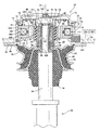
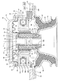
図面を参照して、ダンパ・アッセンブリと車両のフレームとを互いに連結させるための上部装着アッセンブリ(top mount assembly)20を概略的に説明する。図面では、対応する部品には同じ符号を付している。なお、本願の上部装着アッセンブリ20を、限定するものではないが、自動車、モーターサイクル及びレジャー用車両を含む種々の車両において利用できることを記載しておく。図1に、ダンパ・アッセンブリ22のピストンロッド26と車両のフレーム24(概略的に示す)とに接続された本願の上部装着アッセンブリ20の例示的な実施形態を示す。図2に、車両の他の部分から取り外された本願の上部装着アッセンブリ20の例示的な実施形態を示す。
With reference to the drawings, a
上部装着アッセンブリ20は、軸A回りにかつ軸Aに沿って延設される側壁29を有するハウジング28を含む。ハウジング28の側壁29は、略管状の上部本体部分30を有する。上部本体部分30は内面32と外面34とを有する。またハウジング28は、上部本体部分30の外面34から径方向外側に延設する上部フランジ36を有する。側壁29はさらに、上部本体部分30に対して軸方向下方へ延設される下部本体部分38を有する。下部フランジ40は、下部本体部分38から径方向外側に延設され、上部フランジ36の下方に配置されて上部フランジ36に固定される。上部フランジ36と下部フランジ40とは一体に、ハウジング28を車両に接続するために車両のフレーム24に取り付けられる、装着板36,40を構成する(図2参照)。一体的なハウジングを構成するため、上部フランジ36と下部フランジ40とを互いに一体的に接続してもよいことは理解されよう。
The
ロッド接続アッセンブリ42は、ダンパ・アッセンブリ22のピストンロッド26に取り付けられるよう、ハウジング28内に軸Aに沿って配置される。ロッド接続アッセンブリ42とハウジング28との間の相対的移動を可能とするために、弾性部材44がロッド接続アッセンブリ42とハウジング28とを互いに連結させている。例示の実施形態において、弾性部材44は、ゴムなどエラストマー材料で形成される略管状のブッシング44である。なお、ブッシング44を種々の可撓性材料で形成でき、他の形状としてもよいことを記載しておく。
The
流体46を収容するためのチャンバ66,68が、ロッド接続アッセンブリ42とハウジング28との間に形成される。例示の実施形態において、流体46は、磁界に応じて剪断特性が変化することが当該技術において知られている磁性流体46である。より具体的には、磁性流体は、磁界を印加することにより線形性易流動性(free-flowing linear)液体、粘性液体から降伏強度を制御可能な半固形まで可逆的に変化できる。なお、同様な特性を有する他の流体を利用できることを記載しておく。上部本体部分30は、流体46をチャンバ66,68内に受け付けるための注入口48を有する。
可撓性材料の隔壁50が、ハウジング28内に配置されるとともに、外側部分52と内側固定部分54との間で径方向に延設される。外側部分52は、上部本体部分30の内面32と係合する。内側固定部分54は、ロッド接続アッセンブリ42に接続される。隔壁50は、チャンバ66,68の上方境界部分を定義するよう、配置される。また、隔壁50は、チャンバ66,68内での流体46の移動の際に変形することができる。なお、隔壁50とハウジング28/ロッド接続アッセンブリ42との間で所望の接続が得られるよう、内側固定部分54及び/又は外側部分52を、隔壁50の他の部分とは異なる材料、例えば金属などの剛性材料、で形成することができることを記載しておく。
A
ジャウンス・レート・ワッシャ(jounce rate washer)56は、少なくとも部分的に下部本体部分38から径方向内側に配置される。ジャウンス・バンパ(jounce bumper)58(図2参照)は、ジャウンス・レート・ワッシャ56の軸方向下方に配置され、ジャウンス・レート・ワッシャ56と係合する。当該技術において知られている通り、ジャウンス・バンパ58を、ダンパ・アッセンブリ22のピストンロッド26の移動を制限するために配置することができる。エラストマー部材60が、ジャウンス・レート・ワッシャ56と下部本体部分38との間に配置される。エラストマー部材60は、ロッド接続アッセンブリ42とハウジング28との間の相対的な移動の際に撓むことができるように配置される。エラストマー部材60をゴムなど種々のエラストマー材料で形成することができる。リバウンド・レート・ワッシャ(rebound rate washer)62は、チャンバ66,68において、エラストマー部材60の上に被さっている(張り出している)。ジャウンス・レート・ワッシャ56は、ピストンロッド26の圧縮(compression)ストロークの際にエラストマー部材60の下方への移動を制限するよう、配置される。また、リバウンド・レート・ワッシャ62は、ピストンロッド26の反発(rebound)ストロークの際にエラストマー部材60の上方への移動を制限するよう、配置される。これにより、チャンバ66,68を保護して、内部に収容された流体46の漏れを防止している。
A
パーティション・アッセンブリ64は、チャンバ66,68において、径方向において上部本体部分30の内面32とロッド接続アッセンブリ42との間に、かつ、軸方向において隔壁50とエラストマー部材60との間に、配置される。パーティション・アッセンブリ64は、チャンバを、パーティション・アッセンブリ64と隔壁50との間の上部チャンバ領域66と、パーティション・アッセンブリ64とエラストマー部材60との間の下部チャンバ領域68と、に分割する。弾性部材44は、パーティション・アッセンブリ64とロッド接続アッセンブリ42との間に配置され、パーティション・アッセンブリ64とロッド接続アッセンブリ42とに接続される。
The
キャップ70は、径方向において上部本体部分30の内面32に向き合って、軸方向において隔壁50の上方に配置され、隔壁50を保護するよう、軸方向に上部本体部分30を越えて延設される。上部本体部分30の内面32には、キャップ70に隣接して切り欠き72が形成されている。スナップリング74が、切り欠き72に収容され、キャップ70を隔壁50に向かって軸方向に固定するようキャップ70と軸方向に係合する。
The
ロッド接続アッセンブリ42は、上端78と下端80との間で外側壁81に沿って軸方向に延設される略管状のロッド支持部76を有する。弾性部材44は、ロッド支持部76の外側壁81に接続される。より具体的には、内側リング85が、弾性部材44とロッド接続アッセンブリ42とを互いに連結させるよう、弾性部材44とロッド接続アッセンブリ42とに固定されている。さらに、外側リング83が、弾性部材44とパーティション・アッセンブリ64とを互いに連結させるよう、弾性部材とパーティション・アッセンブリ64とに固定されている。例示の実施形態において、外側リング83及び内側リング85は、剛体材料であり、それぞれが弾性部材44に接合されている。また、外側リング83は、パーティション・アッセンブリ64へと圧入されており、そして、内側リング85はロッド支持部76へと圧入されている。他の選択肢として、内側リング85を省略し、弾性部材44をロッド支持部76に直接接合することもできる。ロッド支持部76には、上端78と下端80との間で軸Aに沿って延設されるチャネル82が形成されている。上部ネジ形成部84が、上端78に隣接してチャネル82内に形成されており、また、下部ネジ形成部86が下端80に隣接してチャネル82内に形成されている。
The
軸方向に延びる本体部90とフランジ部分92とを有する上部インサート90,92が設けられている。フランジ部分92は、本体部90から径方向外側に延設される。同様に、軸方向に延びる軸部96とリップ部分98とを有する下部インサート96,98が設けられている。リップ部分98は、軸部96から径方向外側に延設される。上部インサート90,92の本体部90は、ロッド支持部76の上部ネジ形成部84にネジの態様で挿入される。下部インサート96,98の軸部96は、ロッド支持部76の下部ネジ形成部86にネジの態様で挿入される。上部インサート90,92及び下部インサート96,98には、ダンパ・アッセンブリ22のピストンロッド26が挿入される軸方向に延びるロッド通路100が形成されている。図1に示す通り、ピストンロッド26がロッド通路100に挿入された後、ナット102又は他の接続装置を用いて、上部インサート90,92にピストンロッド26を固定することができる。
Upper inserts 90 and 92 having a
隔壁50の内側固定部分54は、上部インサート90,92のフランジ部分92とロッド支持部76との間で軸方向に固定される。したがって、上部インサート90,92がロッド支持部76にネジ締めによって連結されると、上部チャンバ領域66はロッド支持部76において封止される。同様に、ジャウンス・レート・ワッシャ56とリバウンド・レート・ワッシャ62は、下部インサート96,98のリップ部分98とロッド支持部76との間で軸方向に固定される。したがって、下部インサート96,98がロッド支持部76にネジ締めによって連結されると、下部チャンバ領域68はロッド支持部76において封止される。以上の通り、ロッド支持部76と上部インサート90,92と下部インサート96,98とは、一体に、隔壁50とジャウンス・レート・ワッシャ56とリバウンド・レート・ワッシャ62とを定位置に固定するとともに、上部チャンバ領域66及び下部チャンバ領域68に収容された流体46の漏れを防止するため上部チャンバ領域66及び下部チャンバ領域68を確かに封止するための簡単な機構を構成している。部品のこの構成により、従来のピストンロッドを上部装着アッセンブリ20に取り付けることができる利点がある。
The inner fixed
パーティション・アッセンブリ64は、上部本体部分30の内面32に対して径方向に向かって配置されるコイル支持部104,106を有する。コイル支持部104,106は上部部材104と下部部材106とを有する。上部部材104は、下部部材106の軸方向上方に配置される。キャップ70と上部部材104との間でチャンバ66,68を封止するよう、隔壁50の外側部分52は、キャップ70とコイル支持部104,106の上部部材104との間で軸方向に固定される。
The
コイル支持部の上部部材104と下部部材106とによりコイル隔室108が形成される。ボビン110がコイル隔室108内に収容される。磁束リング112が、径方向においてコイル支持部104,106と弾性部材44との間に配置される。磁束リング112は、磁束を集中させるために比較的高透磁率の材料で形成されている。少なくとも一つの流路109が、径方向において磁束リング112とコイル支持部104,106との間に形成されて、上部チャンバ領域66と下部チャンバ領域68との間で軸方向に延設され、これにより、ロッド接続アッセンブリ42に対するハウジング28の移動の際に上部チャンバ領域66と下部チャンバ領域68との間で流体46が通過することができ、減衰効果を生じさせる。
A
少なくとも一つの電磁コイル114が、コイル隔室108においてボビン110回りに配置されて、磁束を磁束リング112へと流路109にわたって伝え、これにより、流路109を通過する磁気粘性流体46の粘度を変化させ、その結果、上部装着アッセンブリ20の減衰特性を変更できる。より具体的には、少なくとも一つの電磁コイル114によって生成された磁束により、磁気粘性流体46の粘度が増加し、これにより、流路109における磁気粘性流体46の剪断抵抗が増加し、その結果、上部装着アッセンブリ20の減衰剛性(damping stiffness)を増加させることができる。なお、任意の数の電磁コイル114を用いることができることを記載しておく。制御器116(概略的に示す)が、少なくとも一つの電磁コイル114に電気的に接続され、電磁コイル114によって生成された流れ(current)を選択的に制御する。さらに、電源118(概略的に示す)が、電磁コイル114に電気的に接続され、電磁コイル114に電力を供給する。電気コネクタ120が、制御器116と電源118との接続ハブを提供するために、電磁コイル114に電気的に接続される。以上の通り、上述の磁性減衰要素により、本願に係る上部装着アッセンブリ20は、複数の周波数における振動を防止又は減衰することができ、車両の走行性、快適性及び操縦性を最適化できる。
At least one
もちろん、本発明には多くの変形及び変更を上記の教示に基づいて行うことができ、詳細な説明に示した以外にも添付の特許請求の範囲内で実現できる。上記の記載が本発明の新規性が有用となるあらゆる組み合わせにわたることは理解されよう。装置の請求項における語「前記」の使用は、それが前出されていて、その請求項又はその請求項が従属する請求項の範囲に含まれていることを意味する明確な引用である。「前記」を使用していないものでも、その請求項又はその請求項が従属する請求項の範囲に含まれている場合もある。 Of course, many variations and modifications may be made in the invention based on the above teachings, and may be practiced within the scope of the appended claims in addition to those set forth in the detailed description. It will be understood that the above description covers all combinations in which the novelty of the present invention is useful. The use of the word “above” in a device claim is a clear citation that means that the claim has been given before and that the claim or the claim is within the scope of the dependent claims. In some cases, the use of “the above” is included in the scope of the claim or the claim on which the claim depends.
20 上部装着アッセンブリ
22 ダンパ・アッセンブリ
24 車両のフレーム
26 ピストンロッド
28 ハウジング
29 側壁
30 上部本体部分
32 内面
34 外面
36 上部フランジ(装着板)
38 下部本体部分
40 下部フランジ(装着板)
42 ロッド接続アッセンブリ
44 弾性部材(ブッシング)
46 流体
48 注入口
50 隔壁
52 外側部分
54 内側固定部分
56 ジャウンス・レート・ワッシャ
58 ジャウンス・バンパ
60 エラストマー部材
62 リバウンド・レート・ワッシャ
64 パーティション・アッセンブリ
66 上部チャンバ領域
68 下部チャンバ領域
70 キャップ
72 切り欠き
74 スナップリング
76 ロッド支持部
78 上端
80 下端
81 外側壁
82 チャネル
83 外側リング
84 上部ネジ形成部
85 内側リング
86 下部ネジ形成部
90 本体部(上部インサート)
92 フランジ部分(上部インサート)
96 軸部(下部インサート)
98 リップ部分(下部インサート)
100 ロッド通路
102 ナット
104 上部部材(コイル支持部)
106 下部部材(コイル支持部)
108 コイル隔室
109 流路
110 ボビン
112 磁束リング
114 電磁コイル
116 制御器
118 電源
120 電気コネクタ
A 軸
20
38
42
46
92 Flange part (upper insert)
96 Shaft (lower insert)
98 Lip part (lower insert)
100
106 Lower member (coil support)
108
Claims (15)
前記車両の前記フレームに接続されるよう軸回りに配置されるハウジングと、
前記ダンパ・アッセンブリのピストンロッドに取り付けられるよう前記ハウジングに配置されるロッド接続アッセンブリと、
流体を収容するよう前記ロッド接続アッセンブリと前記ハウジングとの間に形成されるチャンバと、
前記ロッド接続アッセンブリと前記ハウジングの間に配置されて、前記ロッド接続アッセンブリと前記ハウジングの間との相対的移動を可能にする弾性部材と、
前記弾性部材と前記ハウジングの間に配置されて、軸方向に、前記チャンバを上部チャンバ領域と下部チャンバ領域とに分割するパーティション・アッセンブリであって、前記ハウジングに対する前記ロッド接続アッセンブリの移動を減衰するよう、前記上部チャンバ領域と前記下部チャンバ領域との間に延設されて前記ロッド接続アッセンブリに対する前記ハウジングの移動の際に前記上部チャンバ領域と前記下部チャンバ領域との間で前記流体を通過可能にする少なくとも一つの流路を有するパーティション・アッセンブリと、
前記上部装着アッセンブリの減衰特性を変更するため、前記流路を通過する前記流体の特性を選択的に変更するように前記流路に隣接して配置される少なくとも一つの電磁コイルと、
を備える上部装着アッセンブリ。 An upper mounting assembly for connecting a damper assembly and a vehicle frame to each other,
A housing disposed about an axis to be connected to the frame of the vehicle;
A rod connection assembly disposed in the housing for attachment to a piston rod of the damper assembly;
A chamber formed between the rod connection assembly and the housing to contain a fluid;
An elastic member disposed between the rod connection assembly and the housing to allow relative movement between the rod connection assembly and the housing;
A partition assembly disposed between the elastic member and the housing and axially dividing the chamber into an upper chamber region and a lower chamber region, wherein the rod connection assembly moves relative to the housing. Extending between the upper chamber region and the lower chamber region to allow the fluid to pass between the upper chamber region and the lower chamber region during movement of the housing relative to the rod connection assembly. A partition assembly having at least one flow path,
At least one electromagnetic coil disposed adjacent to the flow path to selectively change the characteristics of the fluid passing through the flow path to change the damping characteristics of the upper mounting assembly;
An upper mounting assembly comprising:
請求項1に記載の上部装着アッセンブリ。 The elastic member is a substantially tubular bushing of rubber material, and the fluid is a magnetorheological fluid.
The top mounting assembly of claim 1.
請求項1又は2に記載の上部装着アッセンブリ。 The housing includes a side wall and a mounting plate that extends radially outward from the side wall and is connected to the frame of the vehicle.
The upper mounting assembly according to claim 1 or 2.
前記ロッド接続アッセンブリには、前記上端と前記下端との間で軸方向に延設されるチャネルが形成され、
前記弾性部材は、前記外側壁と連結されている、
請求項1から3のいずれか1項に記載の上部装着アッセンブリ。 The rod connection assembly has a rod support extending axially along the outer wall between an upper end and a lower end;
The rod connection assembly is formed with a channel extending in the axial direction between the upper end and the lower end,
The elastic member is connected to the outer wall;
The top mounting assembly according to any one of claims 1 to 3.
前記弾性部材と前記ロッド接続アッセンブリとを互いに連結させるよう、前記弾性部材と前記ロッド接続アッセンブリとに固定されている内側リングと、
を更に備える、
請求項4に記載の上部装着アッセンブリ。 An outer ring fixed to the elastic member and the partition assembly to connect the elastic member and the partition assembly to each other;
An inner ring fixed to the elastic member and the rod connection assembly to connect the elastic member and the rod connection assembly to each other;
Further comprising
The top mounting assembly of claim 4.
前記ロッド支持部の前記下端において前記チャネルに挿入されるとともに前記ロッド支持部に連結される軸部を有する下部インサートと、
を更に備え、
前記上部インサート及び前記下部インサートには、前記上部インサート及び前記下部インサートを貫通するよう軸方向に延びる、前記ダンパ・アッセンブリのピストンロッドが挿入される通路が形成されており、
前記上部インサート及び前記下部インサートは、前記チャネルにおいて前記ロッド支持部にネジ締めによって接続される、
請求項4又は5に記載の上部装着アッセンブリ。 An upper insert having a body portion inserted into the channel and connected to the rod support portion at the upper end of the rod support portion;
A lower insert having a shaft portion inserted into the channel and connected to the rod support portion at the lower end of the rod support portion;
Further comprising
In the upper insert and the lower insert, a passage is formed that extends in an axial direction so as to penetrate the upper insert and the lower insert and into which the piston rod of the damper assembly is inserted.
The upper insert and the lower insert are connected to the rod support in the channel by screwing,
6. An upper mounting assembly according to claim 4 or 5.
請求項6に記載の上部装着アッセンブリ。 A partition wall of flexible material extending radially inward from an outer portion adjacent to the housing to an inner fixed portion connected to the rod connection assembly, the partition assembly and the partition wall Further comprising a partition wall defining an upper chamber region therebetween,
The top mounting assembly of claim 6.
前記隔壁の前記内側固定部分は、前記フランジと前記ロッド支持部との間で軸方向に封止するよう固定される、
請求項7に記載の上部装着アッセンブリ。 The upper insert further includes a flange extending radially outward from the body portion outside the channel;
The inner fixed portion of the partition is fixed to be sealed in the axial direction between the flange and the rod support portion.
The top mounting assembly of claim 7.
少なくとも部分的に前記ハウジングから径方向内側にかつ少なくとも部分的に前記ハウジングの軸方向下方に配置されるジャウンス・レート・ワッシャであって、前記エラストマー部材が前記ジャウンス・レート・ワッシャと前記ハウジングとの間に延設されているジャウンス・レート・ワッシャと、
前記ロッド接続アッセンブリに接続されるとともに前記下部チャンバ領域において前記エラストマー部材の上に被さり、前記エラストマー部材の上方向の軸方向移動を制限するリバウンド・レート・ワッシャと、
を更に備え、
前記下部インサートは、前記チャネルの外側にある前記下部インサートの前記軸部から径方向外側に延設されるリップ部分を有しており、
前記ジャウンス・レート・ワッシャと前記リバウンド・レート・ワッシャとは、前記リップ部分と前記ロッド支持部との間で軸方向に封止されている、
請求項7に記載の上部装着アッセンブリ。 An elastomeric member disposed between the housing and the rod connection assembly in a radial direction, the elastomeric member forming a lower chamber region between the partition assembly and the elastomeric member;
A bounce rate washer disposed at least partially radially inward from the housing and at least partially below the housing in an axial direction, wherein the elastomeric member includes the bounce rate washer and the housing. With a bounce rate washer extending in between,
A rebound rate washer connected to the rod connection assembly and overlying the elastomeric member in the lower chamber region to limit upward axial movement of the elastomeric member;
Further comprising
The lower insert has a lip portion extending radially outward from the shaft portion of the lower insert outside the channel;
The jounce rate washer and the rebound rate washer are sealed axially between the lip portion and the rod support.
The top mounting assembly of claim 7.
前記パーティション・アッセンブリは、径方向において前記弾性部材と前記コイル支持部との間に配置される磁束リングを更に有し、
前記少なくとも一つの流路は、前記コイル支持部と前記磁束リングとの間に形成される、
請求項1から9のいずれか1項に記載の上部装着アッセンブリ。 The partition assembly has a coil support portion arranged in a radial direction with respect to the housing;
The partition assembly further includes a magnetic flux ring disposed between the elastic member and the coil support in the radial direction;
The at least one flow path is formed between the coil support and the magnetic flux ring;
10. An upper mounting assembly according to any one of claims 1-9.
前記コイル支持部は、前記流路に隣接するコイル隔室を形成し、
前記流路における前記磁気粘性流体の粘度を変更して前記上部装着アッセンブリの減衰特性を変更するために、前記流路にわたって磁束を生成するように、前記少なくとも一つの電磁コイルが前記コイル隔室に配置され、
前記上部装着アッセンブリは、
前記少なくとも一つの電磁コイルに電気的に接続されて前記電磁コイルへ電力を供給する電源と、
前記少なくとも一つの電磁コイルに接続されて、前記電磁コイルによって生成される磁束を選択的に制御する制御器と、
を更に備える、
請求項10に記載の上部装着アッセンブリ。 The fluid is a magnetorheological fluid;
The coil support portion forms a coil compartment adjacent to the flow path,
The at least one electromagnetic coil is in the coil compartment to generate a magnetic flux across the flow path to change the damping characteristics of the top mounted assembly by changing the viscosity of the magneto-rheological fluid in the flow path. Arranged,
The upper mounting assembly is:
A power source electrically connected to the at least one electromagnetic coil to supply power to the electromagnetic coil;
A controller connected to the at least one electromagnetic coil to selectively control a magnetic flux generated by the electromagnetic coil;
Further comprising
The top mounting assembly of claim 10.
請求項1から5のいずれか1項に記載の上部装着アッセンブリ。 A partition wall of flexible material, the partition wall extending radially between the housing and the rod connection assembly and forming the upper chamber region between the partition assembly and the partition wall; Prepare
The top mounting assembly according to any one of claims 1 to 5.
請求項12に記載の上部装着アッセンブリ。 A cap connected to the housing and at least partially covering the partition to protect the partition during operation of the upper mounting assembly;
The top mounting assembly of claim 12.
請求項12又は13に記載の上部装着アッセンブリ。 An elastomeric member, opposite to the partition wall of the partition assembly, disposed radially between the housing and the rod connection assembly, between the partition assembly and the elastomeric member Further comprising an elastomeric member forming the lower chamber region.
14. An upper mounting assembly according to claim 12 or 13.
前記エラストマー部材は、前記ジャウンス・レート・ワッシャと前記ハウジングとの間に延設され、
前記上部装着アッセンブリは、前記ロッド接続アッセンブリに接続されるとともに前記下部チャンバ領域において前記エラストマー部材の上に被さり、前記エラストマー部材の上方向の軸方向移動を制限するリバウンド・レート・ワッシャを更に備える、
請求項14に記載の上部装着アッセンブリ。 A jounce rate washer disposed at least partially radially inward from the housing and at least partially axially below the housing;
The elastomeric member extends between the jounce rate washer and the housing,
The upper mounting assembly further includes a rebound rate washer connected to the rod connection assembly and overlying the elastomeric member in the lower chamber region to limit upward axial movement of the elastomeric member.
15. A top mounting assembly according to claim 14.
Applications Claiming Priority (4)
| Application Number | Priority Date | Filing Date | Title |
|---|---|---|---|
| US201662321083P | 2016-04-11 | 2016-04-11 | |
| US62/321,083 | 2016-04-11 | ||
| US15/430,868 US9969230B2 (en) | 2016-04-11 | 2017-02-13 | Top mount assembly having adjustable damping characteristics |
| US15/430,868 | 2017-02-13 |
Publications (2)
| Publication Number | Publication Date |
|---|---|
| JP2017190871A true JP2017190871A (en) | 2017-10-19 |
| JP6427614B2 JP6427614B2 (en) | 2018-11-21 |
Family
ID=58461034
Family Applications (1)
| Application Number | Title | Priority Date | Filing Date |
|---|---|---|---|
| JP2017075973A Active JP6427614B2 (en) | 2016-04-11 | 2017-04-06 | Top mounted assembly with adjustable damping characteristics |
Country Status (4)
| Country | Link |
|---|---|
| US (1) | US9969230B2 (en) |
| EP (1) | EP3232082B1 (en) |
| JP (1) | JP6427614B2 (en) |
| CN (1) | CN106917843B (en) |
Cited By (1)
| Publication number | Priority date | Publication date | Assignee | Title |
|---|---|---|---|---|
| JP2023161998A (en) * | 2022-04-26 | 2023-11-08 | 株式会社プロスパイラ | Vibration isolator |
Families Citing this family (14)
| Publication number | Priority date | Publication date | Assignee | Title |
|---|---|---|---|---|
| EP3177849B1 (en) * | 2014-08-04 | 2018-09-12 | Firestone Industrial Products Company, LLC | Performance-variable bushings as well as gas spring and damper assemblies including same |
| US10363789B2 (en) * | 2016-07-07 | 2019-07-30 | The Pullman Company | Top mount assembly with bushing having integral anti-vibration feature |
| FR3054806B1 (en) * | 2016-08-03 | 2019-11-01 | Vibracoustic Nantes Sas | SUPERIOR SUSPENSION SUPPORT COMPRISING A LOCKING MEMBER IN RELATION TO A VEHICLE BODY, AN ASSEMBLY COMPRISING SUCH A SUPPORT, AND A METHOD OF ASSEMBLING SUCH A SUPPORT WITH A VEHICLE BODY |
| US10300953B2 (en) * | 2017-08-03 | 2019-05-28 | The Pullman Company | Hydraulic body mount |
| US10994606B2 (en) * | 2018-07-20 | 2021-05-04 | GM Global Technology Operations LLC | Mount assembly with switchable displacement elements |
| KR102575424B1 (en) * | 2018-08-20 | 2023-09-05 | 현대자동차주식회사 | Active engine mount for vehicle |
| CN109305009B (en) * | 2018-10-30 | 2020-07-31 | 西南交通大学 | A cross-linked maglev suspension outer connecting sleeve for road noise control |
| JP2020133699A (en) * | 2019-02-15 | 2020-08-31 | 本田技研工業株式会社 | Damper mount |
| JP7066647B2 (en) * | 2019-02-15 | 2022-05-13 | 本田技研工業株式会社 | Variable stiffness bush |
| JP2020139546A (en) | 2019-02-27 | 2020-09-03 | 本田技研工業株式会社 | Variable rigidity anti-vibration device |
| CN112879485B (en) * | 2020-04-27 | 2022-11-25 | 北京京西重工有限公司 | Air suspension assembly and bellows for an air suspension assembly |
| US20240326537A1 (en) * | 2023-03-29 | 2024-10-03 | Honda Motor Co., Ltd. | Damper coupler |
| CN118881673B (en) * | 2024-07-11 | 2025-09-19 | 岚图汽车科技有限公司 | Air spring assembly, suspension system and vehicle |
| DE102024206664B4 (en) * | 2024-07-16 | 2026-03-05 | Zf Friedrichshafen Ag | Cover for a bearing point of a vibration damper |
Citations (4)
| Publication number | Priority date | Publication date | Assignee | Title |
|---|---|---|---|---|
| JPS58106209U (en) * | 1982-01-18 | 1983-07-19 | トヨタ自動車株式会社 | Mounting structure for cylindrical shock absorbers |
| JPH0324338A (en) * | 1989-06-08 | 1991-02-01 | Carl Freudenberg:Fa | Hydraulic shock absorbing rubber catch |
| US20050173211A1 (en) * | 2004-02-10 | 2005-08-11 | Hopkins Patrick N. | Reversed decoupler assembly for MR mount |
| US20070144843A1 (en) * | 2005-12-27 | 2007-06-28 | Delphi Technologies, Inc. | MR-fluid hydraulic mount |
Family Cites Families (16)
| Publication number | Priority date | Publication date | Assignee | Title |
|---|---|---|---|---|
| US4711463A (en) | 1986-06-09 | 1987-12-08 | General Motors Corporation | Vehicle suspension strut and upper mount assembly therefor |
| US5158269A (en) | 1990-10-11 | 1992-10-27 | Gencorp Inc. | Dual/slipper shock mount |
| JP2720638B2 (en) * | 1991-06-24 | 1998-03-04 | 日産自動車株式会社 | Vehicle suspension mounting device |
| FR2706558B1 (en) * | 1993-06-16 | 1995-08-25 | Caoutchouc Manuf Plastique | Modular elastic connection assembly forming shock absorber attachment and filter block. |
| JPH11230240A (en) * | 1998-02-16 | 1999-08-27 | Honda Motor Co Ltd | Liquid filled damper mount |
| CN2363125Y (en) * | 1998-10-16 | 2000-02-09 | 西北工业大学 | Damping adjustable current-changing vibration-damper |
| US6186486B1 (en) | 1999-07-30 | 2001-02-13 | Delphi Technologies, Inc. | Jounce bumper plate |
| US6622995B2 (en) | 2001-05-16 | 2003-09-23 | Delphi Technologies, Inc. | Hydraulic mount with magnetorheological fluid |
| KR100488786B1 (en) * | 2002-05-15 | 2005-05-12 | 기아자동차주식회사 | Fluid compressed strut mounting structure |
| US20060125164A1 (en) | 2002-10-23 | 2006-06-15 | Meritor Suspension Systems Company, Inc. | Resilient bushing mount for a vehicle suspension |
| CN2725625Y (en) * | 2004-07-09 | 2005-09-14 | 北京工业大学 | Contravariance magnetic rheological damper |
| CN100478580C (en) * | 2006-09-05 | 2009-04-15 | 北京理工大学 | Inflation damping continuous adjusting current transformation vibration damper |
| US8439336B2 (en) * | 2010-09-01 | 2013-05-14 | GM Global Technology Operations LLC | Dual path hydraulic strut mounts and vehicular suspension systems including the same |
| US9273751B2 (en) | 2011-07-12 | 2016-03-01 | Beijingwest Industries, Co. Ltd. | Double pumper magneto-rheological hydraulic tie bar assembly |
| JP5616563B2 (en) | 2011-07-12 | 2014-10-29 | ベイジンウェスト・インダストリーズ・カンパニー・リミテッドBeijingwest Industries Co., Ltd. | Hydraulic mounting device that supports the vibration source |
| EP3177849B1 (en) * | 2014-08-04 | 2018-09-12 | Firestone Industrial Products Company, LLC | Performance-variable bushings as well as gas spring and damper assemblies including same |
-
2017
- 2017-02-13 US US15/430,868 patent/US9969230B2/en active Active
- 2017-03-29 EP EP17000513.6A patent/EP3232082B1/en active Active
- 2017-04-06 JP JP2017075973A patent/JP6427614B2/en active Active
- 2017-04-10 CN CN201710231192.0A patent/CN106917843B/en active Active
Patent Citations (4)
| Publication number | Priority date | Publication date | Assignee | Title |
|---|---|---|---|---|
| JPS58106209U (en) * | 1982-01-18 | 1983-07-19 | トヨタ自動車株式会社 | Mounting structure for cylindrical shock absorbers |
| JPH0324338A (en) * | 1989-06-08 | 1991-02-01 | Carl Freudenberg:Fa | Hydraulic shock absorbing rubber catch |
| US20050173211A1 (en) * | 2004-02-10 | 2005-08-11 | Hopkins Patrick N. | Reversed decoupler assembly for MR mount |
| US20070144843A1 (en) * | 2005-12-27 | 2007-06-28 | Delphi Technologies, Inc. | MR-fluid hydraulic mount |
Cited By (2)
| Publication number | Priority date | Publication date | Assignee | Title |
|---|---|---|---|---|
| JP2023161998A (en) * | 2022-04-26 | 2023-11-08 | 株式会社プロスパイラ | Vibration isolator |
| JP7763712B2 (en) | 2022-04-26 | 2025-11-04 | 株式会社プロスパイラ | Anti-vibration device |
Also Published As
| Publication number | Publication date |
|---|---|
| US9969230B2 (en) | 2018-05-15 |
| CN106917843A (en) | 2017-07-04 |
| EP3232082B1 (en) | 2019-07-31 |
| US20170291464A1 (en) | 2017-10-12 |
| EP3232082A3 (en) | 2017-11-01 |
| EP3232082A2 (en) | 2017-10-18 |
| JP6427614B2 (en) | 2018-11-21 |
| CN106917843B (en) | 2018-09-18 |
Similar Documents
| Publication | Publication Date | Title |
|---|---|---|
| JP2017190871A (en) | Top mount assembly having adjustable damping characteristics | |
| EP3203107B1 (en) | Liquid-filled bushing | |
| US11193532B2 (en) | Variable stiffness bushing | |
| CN111623075B (en) | Variable-rigidity vibration damper | |
| JP6265562B2 (en) | Vibration isolator | |
| CN111623076B (en) | Variable stiffness damping device | |
| US11446999B2 (en) | Vibration-damping device | |
| CN111623077B (en) | Variable-rigidity vibration damper | |
| JP7145165B2 (en) | Anti-vibration device | |
| US10899215B2 (en) | Hydraulic mount apparatus | |
| JP6545075B2 (en) | Vibration control device | |
| KR101573436B1 (en) | Apparatus for engine mount using mre | |
| US11231083B2 (en) | Anti-vibration device | |
| JP7346189B2 (en) | Vibration isolator | |
| KR20190051224A (en) | Active engine mount | |
| JP4623428B2 (en) | Fluid filled vibration isolator | |
| WO2004067991A1 (en) | Liquid-sealed vibration isolating device |
Legal Events
| Date | Code | Title | Description |
|---|---|---|---|
| A131 | Notification of reasons for refusal |
Free format text: JAPANESE INTERMEDIATE CODE: A131 Effective date: 20180313 |
|
| A521 | Request for written amendment filed |
Free format text: JAPANESE INTERMEDIATE CODE: A523 Effective date: 20180530 |
|
| TRDD | Decision of grant or rejection written | ||
| A01 | Written decision to grant a patent or to grant a registration (utility model) |
Free format text: JAPANESE INTERMEDIATE CODE: A01 Effective date: 20181016 |
|
| A61 | First payment of annual fees (during grant procedure) |
Free format text: JAPANESE INTERMEDIATE CODE: A61 Effective date: 20181029 |
|
| R150 | Certificate of patent or registration of utility model |
Ref document number: 6427614 Country of ref document: JP Free format text: JAPANESE INTERMEDIATE CODE: R150 |
|
| R250 | Receipt of annual fees |
Free format text: JAPANESE INTERMEDIATE CODE: R250 |
|
| R250 | Receipt of annual fees |
Free format text: JAPANESE INTERMEDIATE CODE: R250 |
|
| R250 | Receipt of annual fees |
Free format text: JAPANESE INTERMEDIATE CODE: R250 |
|
| R250 | Receipt of annual fees |
Free format text: JAPANESE INTERMEDIATE CODE: R250 |
|
| R250 | Receipt of annual fees |
Free format text: JAPANESE INTERMEDIATE CODE: R250 |