JP2017190849A - Tapered roller bearing - Google Patents
Tapered roller bearing Download PDFInfo
- Publication number
- JP2017190849A JP2017190849A JP2016082035A JP2016082035A JP2017190849A JP 2017190849 A JP2017190849 A JP 2017190849A JP 2016082035 A JP2016082035 A JP 2016082035A JP 2016082035 A JP2016082035 A JP 2016082035A JP 2017190849 A JP2017190849 A JP 2017190849A
- Authority
- JP
- Japan
- Prior art keywords
- tapered roller
- roller bearing
- lubricating oil
- axial direction
- annular
- Prior art date
- Legal status (The legal status is an assumption and is not a legal conclusion. Google has not performed a legal analysis and makes no representation as to the accuracy of the status listed.)
- Pending
Links
Images

Landscapes
- Rolling Contact Bearings (AREA)
Abstract
【課題】外部の潤滑油を効率的に内部に流入することが可能な円すいころ軸受を提供する。【解決手段】円すいころ軸受1は、外輪10と、内輪20と、複数の円すいころ30と、潤滑油保持部材50と、を備える。潤滑油保持部材50の弾性体部70には、軸受外部の潤滑油Jを軸受内部の空間に流入させるガイド部として、径方向内方から径方向外方に延びるように複数の凸部81が形成されている。【選択図】図3To provide a tapered roller bearing capable of efficiently flowing an external lubricating oil into the inside. A tapered roller bearing (1) includes an outer ring (10), an inner ring (20), a plurality of tapered rollers (30), and a lubricating oil holding member (50). The elastic body portion 70 of the lubricating oil retaining member 50 has a plurality of convex portions 81 as a guide portion for allowing the lubricating oil J outside the bearing to flow into the space inside the bearing so as to extend radially inward to radially outward. Is formed. [Selection] Figure 3
Description
本発明は、円すいころ軸受に関し、特に、円すいころが転動する空間に潤滑油を貯留する円すいころ軸受に関する。 The present invention relates to a tapered roller bearing, and more particularly to a tapered roller bearing that stores lubricating oil in a space in which the tapered roller rolls.
円すいころ軸受は、外輪、内輪、複数の円すいころ、及び保持器を備える。円すいころは、円すいころが転動する軸が、円すいころ軸受の軸心に対して傾斜するように配置されている。円すいころの大径の底面(以下、大端面とも称する。)は、小径の底面(以下、小端面とも称する。)よりも、軸受の径方向外方に配置されている。 The tapered roller bearing includes an outer ring, an inner ring, a plurality of tapered rollers, and a cage. The tapered roller is arranged so that the shaft on which the tapered roller rolls is inclined with respect to the axis of the tapered roller bearing. The large diameter bottom surface (hereinafter also referred to as a large end surface) of the tapered roller is disposed radially outward of the bearing from the small diameter bottom surface (hereinafter also referred to as a small end surface).
円すいころ軸受の特性としては、円すいころの大端面と、内輪のうち円すいころの大端面と接触する面(以下、大つば面とも称する。)との焼き付きに対する耐性を向上させることが求められる。そのため、外輪に潤滑油保持部材を取り付けて、潤滑油保持部材と外輪の間の空間に潤滑油を貯留する円すいころ軸受が知られている(例えば、特許文献1)。 As a characteristic of a tapered roller bearing, it is required to improve resistance to seizure between a large end surface of the tapered roller and a surface (hereinafter, also referred to as a large collar surface) of the inner ring that contacts the large end surface of the tapered roller. For this reason, a tapered roller bearing is known in which a lubricating oil holding member is attached to the outer ring and the lubricating oil is stored in a space between the lubricating oil holding member and the outer ring (for example, Patent Document 1).
このような円すいころ軸受は、例えば、自動車の差動装置などに組み付けられ、ハウジングの内部に配置される。差動装置が駆動すると、円すいころ軸受の内部に貯留された潤滑油の一部は、飛散して円すいころ軸受の外部に流れ出す。円すいころ軸受内部に貯留された潤滑油が減少すると、円すいころ軸受の耐焼き付き性が低下する虞がある。 Such a tapered roller bearing is assembled in, for example, a differential of an automobile and disposed inside the housing. When the differential device is driven, part of the lubricating oil stored in the tapered roller bearing is scattered and flows out of the tapered roller bearing. If the lubricating oil stored in the tapered roller bearing decreases, the seizure resistance of the tapered roller bearing may be reduced.
本発明は、ギヤ等の回転によってハウジング内に飛散した円すいころ軸受の外部の潤滑油を効率的に円すいころ軸受内部に流入させることが可能な円すいころ軸受を提供することを目的とする。 An object of the present invention is to provide a tapered roller bearing capable of efficiently flowing lubricating oil outside the tapered roller bearing scattered into the housing by rotation of a gear or the like into the tapered roller bearing.
本発明の円すいころ軸受は、内周面に第1の軌道面を有する外輪と、外周面に第2の軌道面を有し、外輪と同軸上に配置された内輪と、第1の軌道面及び第2の軌道面の間の空間に配置された複数の円すいころと、外輪と一体に固定された潤滑油保持部材と、を備える。潤滑油保持部材は、軸方向に延びる円筒状に形成され、軸方向における外輪の2つの端部のうち軸方向一方側の端部に固定された筒状部と、径方向に延びる円環状に形成され、径方向外方における端部が筒状部の軸方向一方側の端部に接続された環状部と、を含む。環状部は、軸方向外方の端面及び径方向内方の端部のうち少なくとも一方に形成され、軸受外部に存在する潤滑油を軸受内部の空間に流入させるガイド部を有する。 The tapered roller bearing according to the present invention includes an outer ring having a first raceway surface on an inner peripheral surface, an inner ring having a second raceway surface on an outer peripheral surface and disposed coaxially with the outer ring, and a first raceway surface. And a plurality of tapered rollers disposed in a space between the second raceway surfaces, and a lubricant holding member fixed integrally with the outer ring. The lubricating oil retaining member is formed in a cylindrical shape extending in the axial direction, and has a cylindrical portion fixed to one end portion in the axial direction of two end portions of the outer ring in the axial direction, and an annular shape extending in the radial direction. And an annular portion having a radially outward end connected to an end on one axial side of the tubular portion. The annular portion is formed on at least one of the axially outer end surface and the radially inner end portion, and has a guide portion that allows lubricating oil existing outside the bearing to flow into the space inside the bearing.
本発明の円すいころ軸受のガイド部は、環状部の軸方向外方の端面に、径方向内方から径方向外方に延びるように形成された複数の凸部または凹部であってもよい。 The guide portion of the tapered roller bearing of the present invention may be a plurality of convex portions or concave portions formed on the end surface of the annular portion on the axially outer side so as to extend radially inward to radially outward.
また、本発明の円すいころ軸受のガイド部は、環状部の径方向内方の端部における環状部の径方向内方を向いた内周面が、軸方向内方から軸方向外方に向かって拡径する第1拡径部を含むことにより構成されていてもよい。この場合、第1拡径部の軸方向外方の端部は、環状部の軸方向外方の表面の径方向内方の端部と連続している。 Further, the guide portion of the tapered roller bearing of the present invention has an inner peripheral surface facing the radially inner side of the annular portion at the radially inner end portion of the annular portion from the axially inner side to the axially outer side. It may be comprised by including the 1st enlarged diameter part expanded in diameter. In this case, the axially outward end of the first enlarged diameter portion is continuous with the radially inward end of the axially outward surface of the annular portion.
本発明によれば、円すいころ軸受の外部の潤滑油を効率的に内部に流入することが可能な円すいころ軸受が得られる。 According to the present invention, a tapered roller bearing capable of efficiently flowing lubricating oil outside the tapered roller bearing into the interior is obtained.
本発明の円すいころ軸受は、内周面に第1の軌道面を有する外輪と、外周面に第2の軌道面を有し、外輪と同軸上に配置された内輪と、第1の軌道面及び第2の軌道面の間の空間に配置された複数の円すいころと、外輪と一体に固定された潤滑油保持部材と、を備える。潤滑油保持部材は、軸方向に延びる円筒状に形成され、軸方向における外輪の2つの端部のうち軸方向一方側の端部に固定された筒状部と、径方向に延びる円環状に形成され、径方向外方における端部が筒状部の軸方向一方側の端部に接続された環状部と、を含む。環状部は、軸方向外方の端面及び径方向内方の端部のうち少なくとも一方に形成され、軸受外部に存在する潤滑油を軸受内部の空間に流入させるガイド部を有する。 The tapered roller bearing according to the present invention includes an outer ring having a first raceway surface on an inner peripheral surface, an inner ring having a second raceway surface on an outer peripheral surface and disposed coaxially with the outer ring, and a first raceway surface. And a plurality of tapered rollers disposed in a space between the second raceway surfaces, and a lubricant holding member fixed integrally with the outer ring. The lubricating oil retaining member is formed in a cylindrical shape extending in the axial direction, and has a cylindrical portion fixed to one end portion in the axial direction of two end portions of the outer ring in the axial direction, and an annular shape extending in the radial direction. And an annular portion having a radially outward end connected to an end on one axial side of the tubular portion. The annular portion is formed on at least one of the axially outer end surface and the radially inner end portion, and has a guide portion that allows lubricating oil existing outside the bearing to flow into the space inside the bearing.
上記の構成によれば、潤滑油保持部材の軸方向外方の端面及び径方向内方の端部のうち少なくとも一方に、軸受外部の潤滑油を軸受内部の空間に流入させるガイド部が形成されている。そのため、円すいころ軸受の外部の潤滑油を軸受内部に効率的に流入させることができ、結果として、円すいころ軸受の耐焼き付き性を向上させることができる。 According to the above configuration, the guide portion for allowing the lubricating oil outside the bearing to flow into the space inside the bearing is formed on at least one of the axially outer end surface and the radially inner end portion of the lubricating oil holding member. ing. Therefore, the lubricating oil outside the tapered roller bearing can be efficiently flowed into the bearing, and as a result, the seizure resistance of the tapered roller bearing can be improved.
本発明の円すいころ軸受のガイド部は、環状部の軸方向外方の端面に、径方向内方から径方向外方に延びるように形成された複数の凸部または凹部であり、複数の凸部または凹部の少なくとも1つは、上下方向に延びると共に、上端が径方向外方及び下端が径方向内方を向いて形成されていてもよい。 The guide portion of the tapered roller bearing of the present invention is a plurality of convex portions or concave portions formed on the axially outer end face of the annular portion so as to extend radially inward to radially outward. At least one of the portion or the recess may extend in the vertical direction, and may be formed with the upper end facing radially outward and the lower end facing radially inward.
上記の構成によれば、軸受外部の潤滑油が潤滑油保持部材の環状部の軸方向外方の表面に接触すると、径方向内方から径方向外方に延びた畝状の凸部または凹部に沿って上方から下方に流れることとなる。複数の凸部または凹部のうち、凸部または溝状の凹部の上端が径方向外方及び下端が径方向内方を向いているものについては、凸部または凹部に沿って流れる潤滑油は径方向内方に向かって流れてゆく。このような潤滑油の一部は、環状部の軸方向外方の表面の内周縁から軸受内部の空間に流入することとなる。したがって、凸部または凹部が、軸受外部の潤滑油を軸受内部の空間に流入させるガイド部として機能する。 According to the above configuration, when the lubricating oil outside the bearing comes into contact with the axially outer surface of the annular portion of the lubricating oil retaining member, the bowl-shaped convex portion or concave portion extending radially outward from radially inward Will flow from above to below. Among the plurality of protrusions or recesses, the lubricant flowing along the protrusions or recesses has a diameter when the upper end of the protrusions or groove-like recesses are radially outward and the lower end is radially inward. It flows inward in the direction. A part of such lubricating oil flows into the space inside the bearing from the inner peripheral edge of the axially outer surface of the annular portion. Therefore, the convex portion or the concave portion functions as a guide portion that causes the lubricating oil outside the bearing to flow into the space inside the bearing.
本発明の円すいころ軸受のガイド部は、環状部の径方向内方の端部における環状部の径方向内方を向いた内周面が、軸方向内方から軸方向外方に向かって拡径する第1拡径部を含むことにより構成されていてもよい。この場合、第1拡径部の軸方向外方の端部は、環状部の軸方向外方の表面の径方向内方の端部と連続している。 The guide portion of the tapered roller bearing according to the present invention has an inner peripheral surface that faces the radially inner side of the annular portion at the radially inner end of the annular portion, and extends from the axially inner side toward the axially outer side. You may be comprised by including the 1st enlarged diameter part to diameter. In this case, the axially outward end of the first enlarged diameter portion is continuous with the radially inward end of the axially outward surface of the annular portion.
上記の構成によれば、潤滑油保持部材の環状部の内周面に環状部の軸方向外方の表面の径方向内方の端部と連続する第1拡径部が形成されているので、環状部の軸方向外方の表面を伝ってきた潤滑油は、第1拡径部の表面を伝って軸方向内方にガイドされる。そのため、環状部の軸方向外方の表面を伝ってきた潤滑油が軸受内部の空間に流入しやすくなる。したがって、第1拡径部が、軸受外部の潤滑油を軸受内部の空間に流入させるガイド部として機能することとなる。 According to the above configuration, the first enlarged-diameter portion that is continuous with the radially inner end of the axially outer surface of the annular portion is formed on the inner peripheral surface of the annular portion of the lubricating oil retaining member. The lubricating oil that has traveled along the axially outer surface of the annular portion is guided axially inward along the surface of the first enlarged diameter portion. Therefore, the lubricating oil that has traveled along the axially outer surface of the annular portion easily flows into the space inside the bearing. Therefore, the first diameter-enlarged portion functions as a guide portion that causes the lubricating oil outside the bearing to flow into the space inside the bearing.
本発明の円すいころ軸受のガイド部が、環状部の径方向内方を向いた内周面が第1拡径部を含むことにより構成されている場合、環状部の内周面は、さらに、軸方向外方から軸方向内方に向かって拡径すると共に第1拡径部と連続して第1拡径部の軸方向内方に配置された第2拡径部を含むことが好ましい。 When the guide part of the tapered roller bearing of the present invention is configured such that the inner peripheral surface facing the radially inner side of the annular part includes the first enlarged diameter part, the inner peripheral surface of the annular part further includes: It is preferable to include a second diameter-expanded portion that expands from the axially outward direction toward the axially inward direction and that is continuous with the first diameter-expanded portion and is disposed inward in the axial direction of the first diameter-expanded portion.
上記の構成によれば、潤滑油保持部材の環状部の内周面が、第1拡径部に加えて第2拡径部を有するので、環状部の径方向内方の端部において良好な強度を得ることができる。 According to said structure, since the internal peripheral surface of the annular part of a lubricating oil holding member has a 2nd enlarged diameter part in addition to a 1st enlarged diameter part, it is favorable in the edge part of the radial direction inside of an annular part Strength can be obtained.
本発明の円すいころ軸受の環状部の径方向内方の端部における内周面が第1拡径部と第2拡径部とを含む場合、環状部の内周面において、軸方向に垂直な面と第1拡径部とのなす角の大きさは、軸方向に垂直な面と第2拡径部とのなす角の大きさよりも大きいことが好ましい。 When the inner peripheral surface at the radially inner end of the annular portion of the tapered roller bearing of the present invention includes the first enlarged portion and the second enlarged portion, the inner peripheral surface of the annular portion is perpendicular to the axial direction. It is preferable that the angle formed between the first surface and the first expanded portion is larger than the angle formed between the surface perpendicular to the axial direction and the second expanded portion.
上記の構成によれば、環状部の内周面において、軸方向に垂直な面と第1拡径部とのなす角の大きさは、軸方向に垂直な面と第2拡径部とのなす角の大きさよりも大きい。そのため、環状部の軸方向外方の表面及び第1拡径部を伝ってきた潤滑油が第1拡径部と第2拡径部の連続部分において表面張力で油滴を形成したとき、油滴の重心が、軸方向で、第1拡径部と第2拡径部の連続部分よりも内側にくることとなる。したがって、油滴の重力が表面張力よりも大きくなって第1拡径部と第2拡径部の連続部分から離れるときに、軸方向内方に向かって落下しやすくなり、結果として、効果的に潤滑油を軸受内部の空間に流入させることができる。 According to said structure, the magnitude | size of the angle | corner which the surface perpendicular | vertical to an axial direction and a 1st enlarged diameter part make in the internal peripheral surface of an annular part is the surface perpendicular | vertical to an axial direction, and a 2nd enlarged diameter part It is larger than the size of the corner. Therefore, when the lubricating oil that has transmitted along the axially outer surface of the annular portion and the first enlarged portion forms oil droplets with surface tension at the continuous portion of the first enlarged portion and the second enlarged portion, The center of gravity of the droplet comes to the inside in the axial direction from the continuous portion of the first enlarged diameter portion and the second enlarged diameter portion. Therefore, when the gravity of the oil droplet becomes larger than the surface tension and moves away from the continuous portion of the first enlarged diameter portion and the second enlarged diameter portion, the oil droplet tends to fall inward in the axial direction. The lubricating oil can flow into the space inside the bearing.
本発明の潤滑油保持部材は、金属で形成された芯金と、弾性部材で形成された弾性体部で構成されていてもよい。 The lubricating oil holding member of the present invention may be constituted by a metal core formed of metal and an elastic body portion formed of an elastic member.
また、本発明の潤滑油保持部材は樹脂で形成されていてもよい。 Moreover, the lubricating oil holding member of this invention may be formed with resin.
以下、図面を参照しつつ、本発明の好適な実施の形態について詳細に説明する。以下の説明において参照する各図は、説明の便宜上、本発明の実施形態の構成部材のうち、本発明を説明するために必要な主要部材を示したものである。従って、本発明は以下の各図に示されていない任意の構成部材を備え得る。また、以下の各図中の部材の寸法は、実際の寸法および各部材の寸法比率等を忠実に表したものではない。 Hereinafter, preferred embodiments of the present invention will be described in detail with reference to the drawings. Each drawing referred to in the following description shows, for convenience of description, main members necessary for explaining the present invention among the constituent members of the embodiment of the present invention. Therefore, the present invention can include arbitrary components not shown in the following drawings. In addition, the dimensions of the members in the following drawings do not faithfully represent actual dimensions, dimensional ratios of the members, or the like.
<実施形態1>
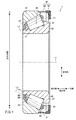
図1は、実施形態1の円すいころ軸受1の断面図である。図1は、円すいころ軸受1の外輪中心軸L1を通る断面図である。なお、本明細書において、単に「軸方向」というときは、外輪中心軸L1の軸方向を意味することとする。
<
FIG. 1 is a sectional view of a tapered
図1に示すように、円すいころ軸受1は、外輪10,内輪20,複数の円すいころ30、保持器40,及び潤滑油保持部材50を備える。外輪10,内輪20、保持器40及び潤滑油保持部材50は、円すいころ軸受1の外輪中心軸L1と同軸上に設けられた環状の部材である。
As shown in FIG. 1, the tapered
外輪10と内輪20とは、図1に示すように、外輪10の径方向内側に内輪20が嵌まるように配置されている。径方向において外輪10と内輪20とで挟まれた空間には、複数の円すいころ30が配置されている。保持器40は、複数の円すいころ30を保持している。潤滑油保持部材50は、外輪10の軸方向の一方の端部に取り付けられている。
As shown in FIG. 1, the
円すいころ30は、円すい台の形状を有する。円すいころ30のころの中心軸L2は、外輪中心軸L1に対して傾斜している。ころの中心軸L2は、円すいころ30の小径側の底面31(以下、小端面31とも称する。)から大径側の底面32(以下、大端面32とも称する。)に向かうにつれて、外輪中心軸L1から離間している。
The tapered
なお、本明細書の以下の記載において、軸方向のうち、内輪20の背面23側の方向を「一方側」、正面24側の方向を「他方側」とする。
In the following description of the present specification, among the axial directions, the direction on the back surface 23 side of the
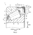
図2は、円すいころ軸受1の一部を拡大した断面図である。
FIG. 2 is an enlarged sectional view of a part of the tapered
外輪10は、内周面に第1の軌道面11を有する。第1の軌道面11は、外輪中心軸L1を中心とした円すい面の一部であり、テーパー形状となっている。
The
外輪10の外周面12には、環状の段差面13が周方向に沿って形成されている。外輪10の段差面13よりも軸方向外方は、軸方向内方よりも径方向の厚さが小さい薄肉部14となっている。段差面13及び薄肉部14は、潤滑油保持部材50を外輪に嵌め合わせるために形成されている。
An
内輪20は、図2に示すように、外周面に第2の軌道面22を有する。第2の軌道面22は、軸方向他方側から一方側に向かうにつれて外輪中心軸L1との距離が大きくなった、テーパー形状となっている。
As shown in FIG. 2, the
内輪20の第2の軌道面22よりも軸方向他方側は、径方向の大きさが第2の軌道面22の軸方向他方側の端部よりも大きく形成されており、円すいころ30の小端面31と対向する小つば部25となっている。また、内輪20の第2の軌道面22よりも軸方向一方側は、径方向の大きさが第2の軌道面22の軸方向一方側の端部よりも大きく形成されており、円すいころ30の大端面32と対向する大つば部26となっている。
The other side of the
図2に示すように、円すいころ30は、第1の軌道面11と第2の軌道面22との間に構成される空間に配置されている。上述のように、複数の円すいころ30のそれぞれは円すい台の形状であり、ころの中心軸L2は、外輪中心軸L1に対して傾斜している。
As shown in FIG. 2, the tapered
保持器40は、図示しないが、軸方向他方側から一方側に向かうにつれて外輪中心軸L1との距離が大きくなるテーパー面を有する円環形状となっている。保持器40のテーパー面には、複数のポケット41が形成されている。テーパー面における複数のポケット41のそれぞれの形状は、円すいころ30の形状に対応する略台形である。保持器40は、金属または樹脂で形成されている。
Although not shown, the
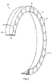
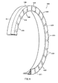
図3は、潤滑油保持部材50の斜視図である。なお、潤滑油保持部材50のうち一部を省略し、部分的に断面を示しているが、実際には、潤滑油保持部材50は、閉じた環状の部材である。潤滑油保持部材50は、図2及び図3に示すように、芯金60と、弾性体部70とで構成されている。
FIG. 3 is a perspective view of the lubricating
図2より、芯金60は、円筒状の芯金本体61と、芯金本体61の一方の端部から径方向内方に突出した環状の爪62と、を含む。芯金本体61と爪62とは、一体に形成されている。芯金本体61の内径の大きさは、外輪10の薄肉部14の外周面15の外側に圧入可能な大きさとなっている。爪62は、芯金本体61の軸方向外側に形成されている。芯金60は、例えば、ステンレス等の金属で形成されている。
As shown in FIG. 2, the
芯金本体61の軸方向内方の端面63は、外輪10の段差面13と略平行に配置された円環状の面である。また、芯金本体61の内周面64は、外輪10の薄肉部14の外周面15と略平行に配置された円筒状の面である。
The axially
弾性体部70の形状は、全体として、軸方向に垂直な円環形状である。弾性体部70のうち径方向外方を構成する部分71は、軸方向内方に向かって延び、外輪中心軸L1に平行で且つ周方向に延びる円筒形状を構成している。弾性体部70は、例えば、ニトリルゴム、アクリルゴム等のゴムで形成されている。
The shape of the
図2に示すように、弾性体部70の径方向内方の端部は、内輪20の大つば部26における径方向外方の端面より径方向外方に存在しており、軸方向一方側から見たときに、環状の隙間Kが存在している。
As shown in FIG. 2, the radially inner end portion of the
芯金60の芯金本体61の一部、及び爪62は、弾性体部70に対して一体に成型され、潤滑油保持部材50を構成している。
A part of the
なお、芯金60と弾性体部70とが一体に成型されることにより、潤滑油保持部材50の形状は、全体として、円環状の環状部51と、筒状部52とが一体となった形状になっている。環状部51は、芯金60の爪62及び弾性体部70に相当する。また、筒状部52は、芯金本体61に相当する。
The
図3に示すように、弾性体部70の軸方向外方の端面73には、複数の凸部81が形成されている。複数の凸部81のそれぞれは、径方向の内方から外方に延びる畝状である。複数の凸部81は、周方向に互いに間隔をあけて、例えば、全体として放射状に配置されている。
As shown in FIG. 3, a plurality of
図2に示すように、芯金60は、芯金本体61の内周面64が外輪10の薄肉部14の外周面15に接触し、芯金本体61の軸方向内方の端面63が外輪10の段差面13に接触するように、外輪10の軸方向一方側の端部に嵌め込まれる。これにより、外輪10と潤滑油保持部材50とが固定される。
As shown in FIG. 2, the
なお、潤滑油保持部材50は、全て樹脂で形成されていてもよい。この場合、潤滑油保持部材50を構成する樹脂としては、ポリフェニレンサルファイド(PPS)樹脂、ナイロン46(PA46)、ナイロン66(PA66)等を用いることができる。
Note that the lubricating
潤滑油保持部材50と外輪10の間に形成される空間には、図1の下部に示すように、潤滑油Jは、円すいころ軸受1の下部に溜まることとなる。
In the space formed between the lubricating
円すいころ軸受1の静止状態においては、潤滑油Jは、外輪10の一部、円すいころ30の一部と接触している。円すいころ軸受1が回転することにより、円すいころ軸受1の下部に溜まった潤滑油Jが回転と共に巻き上げられ、第1の軌道面11及び第2の軌道面22等に供給される。そして、供給された潤滑油Jにより、円すいころ30と第1の軌道面11の間や、円すいころ30と第2の軌道面22の間などに発生する摩擦が低減される。
When the tapered
上記の構成の円すいころ軸受1は、例えば、自動車の差動装置などに組み付けられ、ハウジング(不図示)の内部に配置される。
The tapered
差動装置が駆動すると、円すいころ軸受1の内部に貯留された潤滑油の一部は、飛散して円すいころ軸受1の外部に流れ出す。円すいころ軸受1の内部に貯留された潤滑油Jが減少すると、円すいころ軸受1の耐焼き付き性が低下する虞がある。円すいころ軸受1の耐焼き付き性の低下を抑制するためには、円すいころ軸受1の外部に出た潤滑油Jを、再び、円すいころ軸受1の内部に流入させることが重要である。上述の潤滑油保持部材50に形成された凸部81は、円すいころ軸受1の外部に出た潤滑油Jを再び内部に流入させるためのガイド部として機能する。
When the differential device is driven, a part of the lubricating oil stored in the tapered
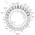
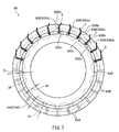
図4は、円すいころ軸受1を軸方向一方側から見たときの円すいころ軸受1の側面図である。複数の凸部81の一部(凸部81のうち、図4において、符号81aでも示しているもの)は、円すいころ軸受1の鉛直方向上下方向に延びると共に、上端81bが径方向外方を向き且つ下端81cが径方向内方を向いている。そのため、円すいころ軸受1の外部に存在し、弾性体部70の表面に付着した潤滑油Jは、弾性体部70の表面を伝って凸部81aに当たると、図4の矢印Dで示すように、畝状の凸部81aの側面に沿って、上端81bから下端81cの方向に流れ落ちる。
FIG. 4 is a side view of the tapered
凸部81aに沿って流れた潤滑油Jは、円すいころ軸受1の軸方向一方側から見て弾性体部70と内輪20の間にできた環状の隙間Kに到達する。そのため、凸部81aが存在することにより、円すいころ軸受1の外部の潤滑油Jが、隙間Kから円すいころ軸受1の内部に流れ込みやすくなる。したがって、本実施形態の円すいころ軸受1によれば、潤滑油Jを円すいころ軸受1の外部から内部に効率的に流入させることができ、結果として、優れた耐焼き付き性を得ることができる。
The lubricating oil J flowing along the
以下、実施形態1の変形例の円すいころ軸受について説明する。
Hereinafter, the tapered roller bearing of the modification of
(変形例1)
図7は、変形例1の潤滑油保持部材50Aを示す。なお、潤滑油保持部材50Aのうち一部を省略し、部分的に断面を示しているが、実際には、潤滑油保持部材50Aは、閉じた環状の部材である。潤滑油保持部材50Aは、芯金60と、弾性体部70Aを含む。芯金60の構成は実施形態1と同一である。
(Modification 1)
FIG. 7 shows a lubricating
弾性体部70Aには、軸方向外方の表面に、畝状の凸部81Aが複数形成されている。また、弾性体部70Aの径方向外方の端部71Aの外周面には、畝状の凸部82Aが複数形成されている。凸部81Aと凸部82Aとは、同数ずつ形成され、凸部81Aの径方向外方の端部と凸部82Aの軸方向外方の端部とが連続するように配置されている。この場合、端面だけでなく径方向外周面に付着した潤滑油Jも軸受内部へ流入させることができ、より多くの潤滑油Jを供給することができる。
In the
変形例1の円すいころ軸受1の構成は、潤滑油保持部材50Aを除いて、実施形態1と同一である。
The configuration of the tapered
(変形例2)
図7は、実施形態1の変形例2の潤滑油保持部材50Bを示す。なお、潤滑油保持部材50Bのうち一部を省略し、部分的に断面を示しているが、実際には、潤滑油保持部材50Bは、閉じた環状の部材である。潤滑油保持部材50Bは、芯金60と、弾性体部70Bを含む。芯金60の構成は実施形態1と同一である。
(Modification 2)
FIG. 7 shows a lubricating
弾性体部70Bには、実施形態1の凸部81の代わりに、軸方向外方の表面に、溝状の凹部83Bが複数形成されている。複数の凹部83Bは、例えば、放射状に配置されている。
In the
変形例2の円すいころ軸受1の構成は、潤滑油保持部材50Bを除いて、実施形態1と同一である。
The configuration of the tapered
図7は、潤滑油保持部材50Bを取り付けた円すいころ軸受1Bを軸方向一方側から見たときの円すいころ軸受1Bの側面図である。複数の凹部83Bの一部(凹部83Bのうち、図7において、符号83Baでも示しているもの)は、円すいころ軸受1Bの鉛直方向の上下方向に延びると共に、上端83Bbが径方向外方を向き且つ下端83Bcが径方向内方を向いている。そのため、円すいころ軸受1Bの外部に存在し、弾性体部70Bの表面に付着した潤滑油Jは、弾性体部70Bの表面を伝って凹部83Baに当たると、図7の矢印Eで示すように、凹部83Bに沿って、上端83Bbから下端83Bcの方向に流れ落ちる。
FIG. 7 is a side view of the tapered
凹部83Baに沿って流れた潤滑油Jは、円すいころ軸受1Bの軸方向一方側から見て弾性体部70Bと内輪20の間にできた環状の隙間Kに到達する。そのため、凹部83Baが存在することにより、円すいころ軸受1Bの外部の潤滑油Jが、隙間Kから円すいころ軸受1Bの内部に流れ込みやすくなる。したがって、円すいころ軸受1Bによれば、潤滑油Jを円すいころ軸受1Bの外部から内部に効率的に流入させることができ、結果として、優れた耐焼き付き性を得ることができる。
The lubricating oil J flowing along the recess 83Ba reaches an annular gap K formed between the
<実施形態2>
図8は、実施形態2の円すいころ軸受1Cの一部を示す断面図である。円すいころ軸受1Cは、外輪10,内輪20,複数の円すいころ30、保持器40,及び潤滑油保持部材50Cを備える。外輪10,内輪20、保持器40及び潤滑油保持部材50Cは、円すいころ軸受1Cの外輪中心軸L1と同軸上に設けられた環状の部材である。外輪10,内輪20,複数の円すいころ30及び保持器40は、実施形態1と同一の構成を有する。
<Embodiment 2>
FIG. 8 is a cross-sectional view showing a part of the tapered
潤滑油保持部材50Cは、実施形態1と同様、外輪10の軸方向の一方の端部に取り付けられている。潤滑油保持部材50Cは、図8に示すように、芯金60と、弾性体部70Cとで構成されている。芯金60は、実施形態1と同一の構成を有する。
The lubricating oil retaining member 50C is attached to one end of the
弾性体部70Cの形状は、実施形態1の弾性体部70と同様、全体として、軸方向に垂直な円環形状である。弾性体部70Cのうち径方向外方を構成する部分71は、軸方向内方に向かって延び、外輪中心軸L1に平行で且つ周方向に延びる円筒形状を構成している。弾性体部70Cは、例えば、ニトリルゴム、アクリルゴム等のゴムで形成されている。
The shape of the
図8に示すように、弾性体部70Cの径方向内方の端部は、内輪20の大つば部26における径方向外方の端面より径方向外方に存在しており、軸方向一方側から見たときに、環状の隙間Kが存在している。
As shown in FIG. 8, the radially inner end portion of the
実施形態1と同様、芯金60の芯金本体61の一部、及び爪62は、弾性体部70Cに対して一体に成型され、潤滑油保持部材50Cを構成している。
As in the first embodiment, a part of the
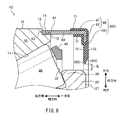
図8に示すように、弾性体部70Cの径方向内方の内周面は、外輪中心軸L1に対して傾斜した2つの環状の面84C,85Cで構成されている。面84Cは、軸方向内方から軸方向外方に向かって拡径する、円環状の第1拡径部84Cである。面85Cは、軸方向外方から軸方向内方に向かって拡径する、円環状の第2拡径部85Cである。第1拡径部84Cの軸方向外方の端部は、弾性体部70Cの軸方向外方の端面73と連続している。第2拡径部85Cの軸方向外方の端部は、第1拡径部84Cの軸方向内方の端部と連続している。第2拡径部85Cの軸方向内方の端部は、弾性体部70Cの軸方向内方の端面75と連続している。
As shown in FIG. 8, the radially inner inner circumferential surface of the
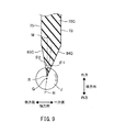
図9は、弾性体部70Cの径方向内方の端部周辺の断面を示す。第1拡径部84Cと第2拡径部85Cが連続している先端縁Rと、弾性体部70Cの軸方向外方の端面73との距離は、先端縁Rと軸方向内方の端面75との距離よりも大きい。また、軸方向に垂直な面(図9の符号Mで示す面を参照。)と第1拡径部84Cとのなす角θ1は、軸方向に垂直な面Mと第2拡径部85Cとのなす角θ2よりも大きい。
FIG. 9 shows a cross section around the radially inner end of the
図8に示すように、芯金60は、芯金本体61の内周面64が外輪10の薄肉部14の外周面15に接触し、芯金本体61の軸方向内方の端面63が外輪10の段差面13に接触するように、外輪10の軸方向一方側の端部に嵌め込まれる。これにより、外輪10と潤滑油保持部材50Cとが固定される。
As shown in FIG. 8, in the
上記の構成の円すいころ軸受1Cは、例えば、自動車の差動装置などに組み付けられ、ハウジング(不図示)の内部に配置される。
The tapered
差動装置が駆動すると、円すいころ軸受1Cの内部に貯留された潤滑油の一部は、飛散して円すいころ軸受1Cの外部に流れ出す。円すいころ軸受1Cの内部に貯留された潤滑油Jが減少すると、円すいころ軸受1Cの耐焼き付き性が低下する虞がある。円すいころ軸受1Cの耐焼き付き性の低下を抑制するためには、円すいころ軸受1Cの外部に出た潤滑油Jを、再び、円すいころ軸受1Cの内部に流入させることが重要である。 When the differential device is driven, a part of the lubricating oil stored in the tapered roller bearing 1C is scattered and flows out of the tapered roller bearing 1C. If the lubricating oil J stored in the tapered roller bearing 1C decreases, the seizure resistance of the tapered roller bearing 1C may be reduced. In order to suppress a decrease in seizure resistance of the tapered roller bearing 1C, it is important that the lubricating oil J that has come out of the tapered roller bearing 1C flows again into the tapered roller bearing 1C.
上述の潤滑油保持部材50Cは、径方向内方の内周面の一部が弾性体部70Cの軸方向外方の端面73と連続する第1拡径部84Cで構成されている。そのため、弾性体部70Cの端面73を伝ってきた潤滑油Jは、第1拡径部84Cに到達すると、第1拡径部84Cの表面を伝って軸方向内方へ移動する。第1拡径部84Cの表面を伝って軸方向内方へ移動してきた潤滑油Jが第1拡径部84Cと第2拡径部85Cとが連続している先端縁Rまでくると、潤滑油Jの一部は、弾性体部70Cを離れて下方へ落ちることとなる。このとき、先端縁Rが弾性体部70Cの端面73よりも軸方向内方に存在しているので、弾性体部70Cを離れて下方へ落ちる潤滑油Jが、円すいころ軸受1Cの内部に入りやすくなる。したがって、本実施形態の円すいころ軸受1Cによれば、潤滑油Jを円すいころ軸受1Cの外部から内部に効率的に流入させることができ、結果として、優れた耐焼き付き性を得ることができる。
The above-described lubricating oil retaining member 50C is configured by a first enlarged-
本実施形態では、第1拡径部84Cと第2拡径部85Cとが連続している先端縁Rと、弾性体部70Cの軸方向外方の端面73との距離は、先端縁Rと軸方向内方の端面75との距離よりも大きいので、先端縁Rまで移動してきた潤滑油Jが弾性体部70Cを離れるとき、効率的に潤滑油Jを軸受内部に流入させることができる。
In the present embodiment, the distance between the distal end edge R where the first
上記のように、先端縁Rまで移動してきた潤滑油Jは、図9に示すように、表面張力によって油滴として先端縁Rに留まることがある。このとき、潤滑油Jの油滴の重心Gは、第1拡径部84Cと第2拡径部85Cから等距離に存在する面N(つまり、外輪中心軸L1を含む断面において、第1拡径部84Cを示す線分と第2拡径部85Cを示す線分とがなす角の二等分線として表される面N)上に位置することとなる。本実施形態では、軸方向に垂直な面Mと第1拡径部84Cとのなす角θ1は、軸方向に垂直な面Mと第2拡径部85Cとのなす角θ2よりも大きいので、潤滑油Jの油滴の重心Gは、先端縁Rよりも軸方向の内方に位置することとなる。そのため、先端縁Rまで移動してきた潤滑油Jが弾性体部70Cを離れるとき、効率的に潤滑油Jを軸受内部に流入させることができる。
As described above, the lubricating oil J that has moved to the leading edge R may remain on the leading edge R as oil droplets due to surface tension, as shown in FIG. At this time, the center of gravity G of the oil droplets of the lubricating oil J has the first expansion in the plane N (that is, the cross section including the outer ring central axis L1) that is equidistant from the first expanded
以下、実施形態2の変形例の円すいころ軸受について説明する。 Hereinafter, the tapered roller bearing of the modification of Embodiment 2 is demonstrated.
(変形例3)
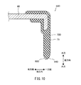
実施形態2では、第1拡径部84Cが軸方向内方から軸方向外方に向かって一定の割合で拡径するテーパー面である場合(つまり、外輪中心軸L1を含む断面において、第1拡径部84Cが直線で表される場合)について説明した。しかしながら、図10に示す変形例3の潤滑油保持部材50Dのように、第1拡径部84Dの軸方向内方から軸方向外方に向かって拡径する割合が、弾性体部70Dの端面73に近づくほど大きくなっていてもよい。言い換えると、外輪中心軸L1を含む断面において、第1拡径部84Dが曲線を描く形状であってもよい。
(Modification 3)
In the second embodiment, when the first diameter-expanded
第1拡径部84Dを図10に示すような曲面とすることにより、第1拡径部84Dと弾性体部70Dの端面73との連続部分を滑らかな曲面とすることができる。そのため、弾性体部70Dの端面73を伝ってきた潤滑油Jが、スムーズに第1拡径部84Dと第2拡径部85Dとの連続部分まで移動することができ、結果として、円すいころ軸受の外部の潤滑油Jを効率よく内部に取り込むことが可能となる。
By forming the first
(変形例4)
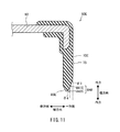
図11は、変形例4の潤滑油保持部材50Eを示す。変形例4のように、潤滑油保持部材50Eの弾性体部70Eの径方向内方の内周面を、第1の面841E及び第2の面842Eからなる第1拡径部84Eと、第2拡径部85Eとで構成してもよい。つまり、第1拡径部84Eの軸方向外側部分を弾性体部70Eの端面73となす角度がθ3である第1の面841Eで構成し、第1拡径部84Eの軸方向内側部分を軸方向に垂直な面となす角θ4がθ3よりも大きい第2の面842Eで構成してもよい。
(Modification 4)
FIG. 11 shows a lubricating
第1拡径部84Eの軸方向外側部分を弾性体部70Eの端面73となす角が小さい第1の面841Eで構成することにより、径方向内方に向かって徐々に角度が大きくなることで弾性体部70Eの端面73を伝ってきた潤滑油Jを効率よく第1拡径部84Eと第2拡径部85Eの連続部分に移動させることができ、結果として、円すいころ軸受の外部の潤滑油Jを効率よく内部に取り込むことが可能となる。
By configuring the axially outer side portion of the first
(変形例5)
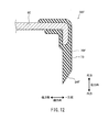
図12は、変形例5の潤滑油保持部材50Fを示す。変形例5のように、弾性体部70Fの径方向内方の内周面を、第1拡径部84Fのみで形成してもよい。ただし、弾性体部70Fの径方向内方の端部において良好な強度を得る観点からは、実施形態2、変形例3及び変形例4のように、第1拡径部に加えて第2拡径部を備えていることが好ましい。
(Modification 5)
FIG. 12 shows a lubricating
実施形態2のその他の変形例の潤滑油保持部材として、実施形態1で説明したように凸部または凹部が形成された弾性体部に対して、実施形態2の第1拡径部84C及び第2拡径部85Cの構成を付加してもよい。
As the lubricating oil retaining member of the other modification of the second embodiment, the first
以上、上述した実施の形態は本発明を実施するための例示に過ぎない。よって、本発明は上述した実施の形態に限定されることなく、その趣旨を逸脱しない範囲内で上述した実施の形態を適宜変形して実施することが可能である。 As mentioned above, embodiment mentioned above is only the illustration for implementing this invention. Therefore, the present invention is not limited to the above-described embodiment, and can be implemented by appropriately modifying the above-described embodiment without departing from the spirit thereof.
1 円すいころ軸受
10 外輪
13 段差面
14 薄肉部
20 内輪
30 円すいころ
40 保持器
50 潤滑油保持部材
51 環状部
52 筒状部
81 凸部(ガイド部)
83B 凹部(ガイド部)
84C 第1拡径部(ガイド部)
85C 第2拡径部
DESCRIPTION OF
83B Concave part (guide part)
84C 1st enlarged diameter part (guide part)
85C second enlarged diameter part
Claims (7)
外周面に第2の軌道面を有し、前記外輪と同軸上に配置された内輪と、
前記第1の軌道面及び前記第2の軌道面の間の空間に配置された複数の円すいころと、
前記外輪と一体に固定された潤滑油保持部材と、
を備え、
前記潤滑油保持部材は、
軸方向に延びる円筒状に形成され、軸方向における前記外輪の2つの端部のうち軸方向一方側の端部に固定された筒状部と、
径方向に延びる円環状に形成され、径方向外方における端部が前記筒状部の軸方向一方側の端部に接続された環状部と、
を含み、
前記環状部は、軸方向外方の端面及び径方向内方の端部のうち少なくとも一方に形成され、軸受外部に存在する潤滑油を軸受内部の空間に流入させるガイド部を有する、円すいころ軸受。 An outer ring having a first raceway surface on the inner peripheral surface;
An inner ring having a second raceway surface on the outer peripheral surface and disposed coaxially with the outer ring;
A plurality of tapered rollers disposed in a space between the first raceway surface and the second raceway surface;
A lubricant holding member fixed integrally with the outer ring;
With
The lubricating oil holding member is
A cylindrical portion that is formed in a cylindrical shape extending in the axial direction and is fixed to an end portion on one axial side of the two end portions of the outer ring in the axial direction;
An annular portion formed in an annular shape extending in the radial direction, and an end portion on the radially outer side connected to an end portion on one axial side of the cylindrical portion;
Including
The annular portion has a guide portion that is formed on at least one of an axially outer end surface and a radially inner end portion, and has a guide portion that allows lubricating oil existing outside the bearing to flow into a space inside the bearing. .
前記ガイド部は、前記環状部の軸方向外方の端面に、径方向内方から径方向外方に延びるように形成された複数の凸部または凹部であり、
前記複数の凸部または凹部の少なくとも1つは、上下方向に延びると共に、上端が径方向外方及び下端が径方向内方を向いて形成されている、円すいころ軸受。 The tapered roller bearing according to claim 1,
The guide portion is a plurality of convex portions or concave portions formed on the end surface on the axially outer side of the annular portion so as to extend from the radially inner side to the radially outer side,
A tapered roller bearing in which at least one of the plurality of convex portions or concave portions extends in the vertical direction, and has an upper end formed radially outward and a lower end directed radially inward.
前記ガイド部は、前記環状部の径方向内方の端部における内周面が、軸方向内方から軸方向外方に向かって拡径する第1拡径部を含むことにより構成され、
前記第1拡径部の軸方向外方の端部は、前記環状部の軸方向外方の端面と連続している、円すいころ軸受。 The tapered roller bearing according to claim 1,
The guide portion is configured by including a first diameter-expanded portion in which an inner peripheral surface at an end portion on the radially inner side of the annular portion expands from the axially inner side toward the axially outer side,
A tapered roller bearing, wherein an axially outer end portion of the first enlarged diameter portion is continuous with an axially outer end surface of the annular portion.
前記環状部の径方向内方の端部における内周面は、さらに、軸方向外方から軸方向内方に向かって拡径すると共に前記第1拡径部と連続して前記第1拡径部の軸方向内方に配置された第2拡径部を含む、円すいころ軸受。 The tapered roller bearing according to claim 3,
The inner peripheral surface at the radially inner end of the annular portion further expands from the axially outer side toward the axially inner side and continues to the first increased diameter portion. A tapered roller bearing including a second diameter-expanded portion disposed inward in the axial direction of the portion.
前記環状部の前記内周面において、軸方向に垂直な面と前記第1拡径部とのなす角の大きさは、軸方向に垂直な面と前記第2拡径部とのなす角の大きさよりも大きい、円すいころ軸受。 The tapered roller bearing according to claim 4,
In the inner peripheral surface of the annular portion, the angle between the surface perpendicular to the axial direction and the first enlarged diameter portion is the angle between the surface perpendicular to the axial direction and the second enlarged diameter portion. Tapered roller bearings larger than size.
前記潤滑油保持部材は、
金属で形成された芯金と、
弾性部材で形成された弾性体部で構成されている、円すいころ軸受。 In the tapered roller bearing according to any one of claims 1 to 5,
The lubricating oil holding member is
A metal core made of metal,
A tapered roller bearing comprising an elastic body portion formed of an elastic member.
前記潤滑油保持部材は樹脂で形成されている、円すいころ軸受。
In the tapered roller bearing according to any one of claims 1 to 5,
A tapered roller bearing in which the lubricating oil retaining member is made of resin.
Priority Applications (1)
| Application Number | Priority Date | Filing Date | Title |
|---|---|---|---|
| JP2016082035A JP2017190849A (en) | 2016-04-15 | 2016-04-15 | Tapered roller bearing |
Applications Claiming Priority (1)
| Application Number | Priority Date | Filing Date | Title |
|---|---|---|---|
| JP2016082035A JP2017190849A (en) | 2016-04-15 | 2016-04-15 | Tapered roller bearing |
Publications (1)
| Publication Number | Publication Date |
|---|---|
| JP2017190849A true JP2017190849A (en) | 2017-10-19 |
Family
ID=60085843
Family Applications (1)
| Application Number | Title | Priority Date | Filing Date |
|---|---|---|---|
| JP2016082035A Pending JP2017190849A (en) | 2016-04-15 | 2016-04-15 | Tapered roller bearing |
Country Status (1)
| Country | Link |
|---|---|
| JP (1) | JP2017190849A (en) |
Cited By (2)
| Publication number | Priority date | Publication date | Assignee | Title |
|---|---|---|---|---|
| US10280978B2 (en) * | 2016-12-22 | 2019-05-07 | Jtekt Corporation | Tapered roller bearing |
| US10364845B2 (en) | 2016-12-22 | 2019-07-30 | Jtekt Corporation | Tapered roller bearing |
-
2016
- 2016-04-15 JP JP2016082035A patent/JP2017190849A/en active Pending
Cited By (2)
| Publication number | Priority date | Publication date | Assignee | Title |
|---|---|---|---|---|
| US10280978B2 (en) * | 2016-12-22 | 2019-05-07 | Jtekt Corporation | Tapered roller bearing |
| US10364845B2 (en) | 2016-12-22 | 2019-07-30 | Jtekt Corporation | Tapered roller bearing |
Similar Documents
| Publication | Publication Date | Title |
|---|---|---|
| JP5343457B2 (en) | Roller bearing cage | |
| US9683599B2 (en) | Tapered roller bearing | |
| JP6816390B2 (en) | Tapered roller bearing | |
| KR20220137079A (en) | Tubular retainers and ball bearings for ball bearings | |
| JP4946881B2 (en) | Rolling bearing | |
| JP5125820B2 (en) | Tapered roller bearing | |
| JP5109721B2 (en) | Tapered roller bearing | |
| JP2017190849A (en) | Tapered roller bearing | |
| WO2015129709A1 (en) | Tapered roller bearing | |
| JP6672059B2 (en) | Crown type cage and ball bearing | |
| JP4930142B2 (en) | Roller bearing cage | |
| JP6076610B2 (en) | Roller bearing cage | |
| JP6736875B2 (en) | Tapered roller bearing | |
| JP2012163217A (en) | Tapered roller bearing | |
| JP2019173774A (en) | Cage and roller | |
| CN107588094A (en) | Taper roll bearing | |
| CN108253016B (en) | Tapered roller bearing | |
| WO2020189439A1 (en) | Inner-ring-separable angular ball bearing | |
| JP2018135957A (en) | Conical roller bearing | |
| CN110566584A (en) | Thrust needle roller bearing | |
| WO2019198762A1 (en) | Crown-shaped retainer for deep-groove ball bearing, and deep-groove ball bearing | |
| JP7515305B2 (en) | Tapered roller bearings | |
| JP6729117B2 (en) | Tapered roller bearing | |
| CN108223564B (en) | Tapered roller bearing | |
| JP2011137395A (en) | Bearing device for turbocharger |