JP2017190839A - Coupling structure and coupling structure nut - Google Patents
Coupling structure and coupling structure nut Download PDFInfo
- Publication number
- JP2017190839A JP2017190839A JP2016081403A JP2016081403A JP2017190839A JP 2017190839 A JP2017190839 A JP 2017190839A JP 2016081403 A JP2016081403 A JP 2016081403A JP 2016081403 A JP2016081403 A JP 2016081403A JP 2017190839 A JP2017190839 A JP 2017190839A
- Authority
- JP
- Japan
- Prior art keywords
- external communication
- flange
- coupling structure
- nut
- coupling
- Prior art date
- Legal status (The legal status is an assumption and is not a legal conclusion. Google has not performed a legal analysis and makes no representation as to the accuracy of the status listed.)
- Granted
Links
Images
Landscapes
- Bolts, Nuts, And Washers (AREA)
Abstract
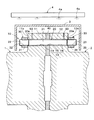
【課題】回転時にボルト孔内に油が滞留することによって異常振動が発生することを防止できるカップリング構造を提供する。【解決手段】実施の形態によるカップリング構造10は、第1フランジ11および第2フランジ12を貫通するボルト孔13と、ボルト孔13を貫通し、第1フランジ11と第2フランジ12とを締結するカップリングボルト20と、を備えている。カップリングボルト20は、カップリング構造用ナット30、33によって締め付けられている。ボルト孔13は、外部連通部50によって外部に連通している。【選択図】図1An object of the present invention is to provide a coupling structure capable of preventing abnormal vibration from occurring due to retention of oil in a bolt hole during rotation. A coupling structure (10) according to an embodiment includes a bolt hole (13) passing through a first flange (11) and a second flange (12), and a bolt hole (13) passing through the bolt hole (13) to fasten the first flange (11) and the second flange (12). and a coupling bolt 20 that The coupling bolt 20 is tightened by coupling structure nuts 30 and 33 . The bolt hole 13 communicates with the outside through an external communication portion 50 . [Selection drawing] Fig. 1
Description
本発明の実施の形態は、カップリング構造およびカップリング構造用ナットに関する。 Embodiments described herein relate generally to a coupling structure and a coupling structure nut.
従来より、2つのロータを、カップリング構造を用いて結合することが知られている。例えば、発電プラントでは、複数のタービンのタービンロータ同士がカップリング構造によって結合され、また、タービンロータと、発電機の発電機ロータとがカップリング構造によって結合されている。このようにして、各タービンのタービンロータの回転力が、発電機の発電機ロータに伝達されるようになっている。カップリング構造についてより詳細に説明すると、各ロータの端部にフランジが設けられており、隣り合うフランジをカップリングボルトが貫通している。そして、カップリングボルトにナットが締め付けられることにより、各ロータが締結されている。各フランジには、カップリングボルトが貫通するボルト孔が設けられている。 Conventionally, it is known to couple two rotors using a coupling structure. For example, in a power plant, turbine rotors of a plurality of turbines are coupled by a coupling structure, and a turbine rotor and a generator rotor of a generator are coupled by a coupling structure. In this way, the rotational force of the turbine rotor of each turbine is transmitted to the generator rotor of the generator. If it demonstrates in detail about a coupling structure, the flange is provided in the edge part of each rotor, and the coupling bolt has penetrated the adjacent flange. Each nut is fastened by tightening a nut on the coupling bolt. Each flange is provided with a bolt hole through which the coupling bolt passes.
ところで、カップリング構造の周囲には、ロータを冷却するための冷却油が噴霧されている。このことにより、噴霧されてミスト状になった冷却油が、カップリング構造の周囲で浮遊し、カップリング構造の周囲が油雰囲気になり、カップリング構造がミスト状の冷却油に曝される。ミスト状の冷却油は、ナットとフランジとの隙間や、ナットのねじ孔とカップリングボルトとの隙間を通って、フランジに設けられたボルト孔に侵入する場合がある。とりわけ、ロータ回転時には、ナットは遠心力によるモーメントを受ける。このモーメントによって、ナットのフランジに当接する面のうちロータ中心軸の側の部分において、フランジに対する面圧が低減し、ナットの当該部分とフランジとの間に微少な隙間が形成され得る。この隙間を通ってボルト孔に冷却油が侵入し得る。ボルト孔に侵入した冷却油は、遠心力を受けてボルト孔内の外周側に移動し、そこに滞留する。 By the way, cooling oil for cooling the rotor is sprayed around the coupling structure. As a result, the sprayed and mist-like cooling oil floats around the coupling structure, the surrounding of the coupling structure becomes an oil atmosphere, and the coupling structure is exposed to the mist-like cooling oil. The mist-like cooling oil may enter the bolt hole provided in the flange through the gap between the nut and the flange or the gap between the screw hole of the nut and the coupling bolt. In particular, when the rotor rotates, the nut receives a moment due to centrifugal force. Due to this moment, the surface pressure against the flange is reduced in the portion on the rotor central axis side of the surface in contact with the flange of the nut, and a minute gap can be formed between the portion of the nut and the flange. Cooling oil can enter the bolt hole through this gap. The cooling oil that has entered the bolt hole receives centrifugal force, moves to the outer peripheral side in the bolt hole, and stays there.
このようにしてボルト孔内に冷却油が滞留すると、ロータの回転バランスが崩れる可能性がある。すなわち、ボルト孔は、ロータのフランジにおいて周方向に離間して複数設けられているが、各ボルト孔内における冷却油の滞留量が異なる場合には、ロータの回転バランスが崩れる。このことにより、ロータの回転のアンバランスが生じ、ロータが振れ回り、ロータの異常振動が発生する場合がある。 If the cooling oil stays in the bolt hole in this way, the rotational balance of the rotor may be lost. That is, a plurality of bolt holes are provided spaced apart in the circumferential direction in the flange of the rotor, but if the amount of cooling oil staying in each bolt hole is different, the rotational balance of the rotor is lost. This may cause an unbalance in the rotation of the rotor, causing the rotor to swing around and causing abnormal vibration of the rotor.
本発明は、このような点を考慮してなされたものであり、回転時にボルト孔内に油が滞留することによって異常振動が発生することを防止できるカップリング構造およびカップリング構造用ナットを提供することを目的とする。 The present invention has been made in view of the above points, and provides a coupling structure and a coupling structure nut that can prevent abnormal vibration from occurring due to oil remaining in the bolt hole during rotation. The purpose is to do.
実施の形態によるカップリング構造は、第1ロータと第2ロータとを結合する。このカップリング構造は、第1ロータの端部に設けられた第1フランジと、第2ロータの第1ロータの側の端部に設けられた第2フランジと、を備えている。また、カップリング構造は、第1フランジおよび第2フランジを貫通するボルト孔と、ボルト孔を貫通し、第1フランジと第2フランジとを締結するカップリングボルトと、を備えている。カップリングボルトは、カップリング構造用ナットによって締め付けられている。ボルト孔は、外部連通部によって外部に連通している。 The coupling structure according to the embodiment couples the first rotor and the second rotor. The coupling structure includes a first flange provided at an end portion of the first rotor and a second flange provided at an end portion of the second rotor on the first rotor side. The coupling structure includes a bolt hole that passes through the first flange and the second flange, and a coupling bolt that passes through the bolt hole and fastens the first flange and the second flange. The coupling bolt is tightened by a coupling structure nut. The bolt hole communicates with the outside through an external communication portion.
実施の形態によるカップリング構造用ナットは、第1ロータと第2ロータとを結合するカップリング構造に用いられる。また、このカップリング構造用ナットは、第1ロータの第1フランジおよび第2ロータの第2フランジを貫通するボルト孔を貫通し、第1フランジと第2フランジとを締結するカップリングボルトに締め付けられる。カップリング構造用ナットは、カップリングボルトに螺合するねじ孔と、ねじ孔から放射状に延びる複数の外部連通部と、を備えている。 The nut for coupling structure by embodiment is used for the coupling structure which couple | bonds a 1st rotor and a 2nd rotor. The coupling structure nut passes through a bolt hole that passes through the first flange of the first rotor and the second flange of the second rotor, and is tightened to a coupling bolt that fastens the first flange and the second flange. It is done. The coupling structure nut includes a screw hole that is screwed into the coupling bolt, and a plurality of external communication portions that extend radially from the screw hole.
本発明によれば、回転時にボルト孔内に油が滞留することによって異常振動が発生することを防止できる。 According to the present invention, it is possible to prevent abnormal vibration from occurring due to oil remaining in the bolt hole during rotation.
以下、図面を参照して、本発明の実施の形態におけるカップリング構造およびカップリング構造用ナットについて説明する。ここで、カップリング構造は、第1ロータと第2ロータとを結合するためのものである。例えば、カップリング構造は、複数のタービンのタービンロータ同士を結合したり、タービンロータと、発電機の発電機ロータとを結合したりするためのものである。タービンの例としては、特に限られることはないが、蒸気タービンやガスタービン等を挙げることができ、タービンロータ同士を結合する例としては、例えば、蒸気タービンの高圧タービンと低圧タービンとを結合する例が挙げられる。上述した第1ロータおよび第2ロータという用語は、これらの各種タービンのタービンロータ、または発電機の発電機ロータに相当するものとして用いている。 Hereinafter, a coupling structure and a coupling structure nut in an embodiment of the present invention will be described with reference to the drawings. Here, the coupling structure is for coupling the first rotor and the second rotor. For example, the coupling structure is for coupling turbine rotors of a plurality of turbines, or coupling a turbine rotor and a generator rotor of a generator. Examples of the turbine are not particularly limited, and examples thereof include a steam turbine and a gas turbine. Examples of coupling turbine rotors include, for example, coupling a high-pressure turbine and a low-pressure turbine of a steam turbine. An example is given. The terms “first rotor” and “second rotor” described above are used to correspond to the turbine rotor of these various turbines or the generator rotor of the generator.
(第1の実施の形態)
図1乃至図4を用いて、第1の実施の形態におけるカップリング構造およびカップリング構造用ナットについて説明する。このうち図1には、第1ロータ1と第2ロータ2とを結合したカップリング構造10の全体構成が示されている。
(First embodiment)
The coupling structure and the coupling structure nut in the first embodiment will be described with reference to FIGS. 1 to 4. Among these, FIG. 1 shows an overall configuration of a
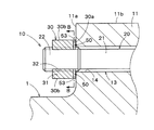
図1に示すように、カップリング構造10は、第1ロータ1の一方の端部に設けられた第1フランジ11と、第2ロータ2の一方の端部(第1ロータ1の側の端部)に設けられた第2フランジ12と、第1フランジ11および第2フランジ12を貫通するボルト孔13と、を備えている。このうちボルト孔13に、第1フランジ11と第2フランジ12とを締結するカップリングボルト20が貫通している。カップリングボルト20は、第1ナット30(カップリング構造用ナット)および第2ナット33(カップリング構造用ナット)によって締め付けられている。なお、図1に示す例では、第1フランジ11と第2フランジ12との間に、リング状のスペーサ40が介在されている。
As shown in FIG. 1, the
ボルト孔13は、第1フランジ11に設けられた第1ボルト孔部分14と、第2フランジ12に設けられた第2ボルト孔部分15と、スペーサ40に設けられたスペーサボルト孔部分16と、を有している。これらの第1ボルト孔部分14と第2ボルト孔部分15とスペーサボルト孔部分16は同軸上に配置されており、カップリングボルト20が挿入されて貫通するようになっている。このように構成されたボルト孔13は、第1ロータ1(または第2ロータ2)の中心軸に対する周方向に離間して複数形成されており、第1フランジ11と第2フランジ12とが、複数のカップリングボルト20によって締結されるようになっている。
The
図1に示すように、本実施の形態によるカップリングボルト20は、植込みボルト(またはスタッドボルト)状に形成されている。このカップリングボルト20は、ボルト本体21と、ボルト本体21の一方の端部(第1フランジ11の側の端部)に設けられた第11ねじ部と、ボルト本体21の他方の端部(第2フランジ12の側の端部)に設けられた第2ねじ部23と、を有している。このうち第1ねじ部22は、第1フランジ11の背面11a(第2フランジ12の側とは反対側の面)から突出し、第2ねじ部23は、第2フランジ12の背面12a(第1フランジ11の側とは反対側の面)から突出している。第1ねじ部22に、第1ナット30が締め付けられ、第1ナット30の第1フランジ11の側の面(当接面30a)は、第1フランジ11の背面11aに当接している。一方、第2ねじ部23に、第2ナット33が締め付けられ、第2ナット33の第2フランジ12の側の面(当接面33a)は、第2フランジ12の背面12aに当接している。このようにして、第1ロータ1に設けられた第1フランジ11と第2ロータ2に設けられた第2フランジ12とが締結されている。
As shown in FIG. 1, the
第1ナット30は、ナット本体31と、ナット本体31を貫通するとともに、カップリングボルト20の第1ねじ部22に螺合するねじ孔32と、を有している。同様に、第2ナット33は、ナット本体34と、ナット本体34を貫通するとともに、カップリングボルト20の第2ねじ部23に螺合するねじ孔35と、を有している。本実施の形態では、カップリングボルト20の第1ねじ部22が第1ナット30を貫通して第1ナット30から突出し、第2ねじ部23が第2ナット33を貫通して第2ナット33から突出している。
The
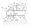
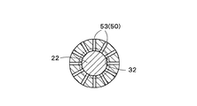
図2に示すように、ボルト孔13は、外部連通部50によってフランジ11、12の外部に連通している。この外部連通部50によって、ボルト孔13に侵入した冷却油(後述)が排出されるようになっている。
As shown in FIG. 2, the
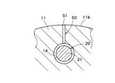
図2および図3に示すように、本実施の形態による外部連通部50は、第1フランジ11に設けられており、ボルト孔13から半径方向外側(第1ロータ1の中心軸に対する半径方向外側)に延びている。より具体的には、外部連通部50は、ボルト孔13から半径方向外側に延びる外部連通孔51を含んでいる。この外部連通孔51は、第1フランジ11の背面11aから離間し、第1ボルト孔部分14から第1フランジ11の外周面11bまで半径方向外側に延びている。
As shown in FIGS. 2 and 3, the
なお、外部連通部50は、第1フランジ11に設けられていることに限られることはない。例えば、外部連通部50は、図1に示すように、第2フランジ12に設けられていてもよい。この場合においても、外部連通部50は、上述した構成と同様に構成することができ、同様の効果を奏することができる。更には、外部連通部50は、第1フランジ11および第2フランジ12にそれぞれ設けられていてもよい。この場合には、ボルト孔13内からの冷却油の排出効率を向上させることができる。なお、外部連通部50は、第1フランジ11に複数設けられてもよく、第2フランジ12に複数設けられていてもよい。以下の説明では、便宜上、第1フランジ11または第1ナット30の側に外部連通部50が設けられる例について説明し、第2フランジ12または第2ナット33の側に外部連通部50が設けられる例についての説明は省略する。
The
ところで、図1に示すように、第1フランジ11と第2フランジ12は、図1の断面視で逆コの字状に形成されたカップリングカバー3によって覆われている。このカップリングカバー3は、第1フランジ11および第2フランジ12のうち上半部分を覆うように、各ロータ1、2の軸方向から見たときに半円状に形成されている。カップリングカバー3の上方には、カップリングシャワー部4が設けられている。このカップリングシャワー部4には、図示しない冷却油供給部から冷却油が供給され、カップリングシャワー部4の複数のノズル孔4aから冷却油が噴霧されるように構成されている。このカップリングシャワー部4から、カップリングカバー3、並びにカップリングカバー3の周囲の第1ロータ1の外周面および第2ロータ2の外周面に、冷却油が噴霧される。このことにより、カップリングカバー3、第1ロータ1の外周面、および第2ロータ2の外周面が冷却されるようになっている。
By the way, as shown in FIG. 1, the
次に、このような構成からなる本実施の形態の作用について説明する。 Next, the operation of the present embodiment having such a configuration will be described.
図1に示す第1ロータ1が回転している間、カップリングシャワー部4から冷却油が噴霧される。このことにより、噴霧されてミスト状になった冷却油は、カップリングカバー3の外周面、並びにカップリングカバー3の周囲の第1ロータ1の外周面および第2ロータ2の外周面に達するが、冷却油の一部は、カップリングカバー3内の空間に流入して、カップリング構造10の周囲で浮遊する。このようにして、カップリング構造10の周囲が油雰囲気になり、カップリング構造10は、ミスト状の油雰囲気に曝される。
While the
第1ロータ1の回転中、第1ナット30は、遠心力によってモーメントを受ける。このモーメントによって、第1ナット30の当接面30aのうち第1ロータ1の中心軸の側(図2に示す下側)の部分において、第1フランジ11に対する面圧が低減し、第1ナット30の当該部分と第1フランジ11の背面11aとの間に微小な隙間が形成され得る。この隙間を通る侵入経路P1(図2参照)によって、ミスト状の冷却油がボルト孔13(ボルト孔13とボルト本体21との間の隙間)に侵入し得る。また、別の経路として、第1ナット30のねじ孔32と、カップリングボルト20の第1ねじ部22との間の隙間を通る侵入経路P2によっても、ミスト状の冷却油がボルト孔13に侵入し得る。
During the rotation of the
しかしながら、ボルト孔13に侵入した冷却油は、外部連通孔51に達すると、第1ロータ1の回転によって生じる遠心力により、外部連通孔51内を半径方向外側に向かって流れる。このことにより、冷却油は外部連通孔51から第1フランジ11の外部に排出される。
However, when the cooling oil that has entered the bolt holes 13 reaches the external communication holes 51, the cooling oil flows radially outward in the external communication holes 51 due to the centrifugal force generated by the rotation of the
このように本実施の形態によれば、ボルト孔13を外部に連通する外部連通部50により、ボルト孔13に侵入した冷却油を排出することができる。このことにより、ボルト孔13内に冷却油が滞留することを防止でき、第1ロータ1および第2ロータ2の回転のアンバランスが生じることを防止できる。このため、回転時にボルト孔13内に冷却油が滞留することによって異常振動が発生することを防止できる。
Thus, according to the present embodiment, the cooling oil that has entered the
また、本実施の形態によれば、外部連通部50が、ボルト孔13から半径方向外側に延びている。このことにより、ボルト孔13内の冷却油を、遠心力を利用してスムースに排出することができる。このため、回転時にボルト孔13内に冷却油が滞留することをより一層防止でき、異常振動が発生することをより一層防止できる。
Further, according to the present embodiment, the
さらに、本実施の形態によれば、外部連通部50は、ボルト孔13から延びる外部連通孔51を含んでいる。このことにより、外部連通部50を、ボルト孔13のうち軸方向中央部分に近づけることができ、当該部分に滞留した冷却油であっても、スムースに排出することができる。このため、回転時にボルト孔13内に冷却油が滞留することをより一層防止でき、異常振動が発生することをより一層防止できる。また、外部連通孔51は、第1フランジ11の背面11aから離間して設けられるため、第1ナット30の当接面30aを全体的に第1フランジ11の背面11aに当接させることができ、第1ナット30の締め付けを安定化させることができる。
Furthermore, according to the present embodiment, the
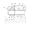
なお、上述した本実施の形態においては、外部連通部50が、ボルト孔13から延びる外部連通孔51を含んでいる例について説明した。しかしながら、このことに限られることはなく、例えば、図4に示すように、外部連通部50は、第1フランジ11の背面11aに設けられた、ボルト孔13から延びる外部連通溝52を含んでいてもよい。この外部連通溝52は、第1ボルト孔部分14から第1フランジ11の外周面11bまで半径方向外側に延びている。このような変形例によれば、外部連通部50の機械加工性を向上させることができる。また、図2および図3に示す外部連通孔51と同様に、ボルト孔13内に冷却油が滞留することを防止できる。
In the above-described embodiment, the example in which the
また、上述した本実施の形態においては、カップリングボルト20が、植込みボルト状に形成され、第1ナット30および第2ナット33によって締め付けられている例について説明した。しかしながら、このことに限られることはなく、カップリングボルト20が頭付きボルト(図示せず)状に形成され、ボルトの第2ねじ部23の代りにボルト頭が設けられていてもよい。
Moreover, in this Embodiment mentioned above, the
(第2の実施の形態)
次に、図5乃至図7を用いて、本発明の第2の実施の形態におけるカップリング構造およびカップリング構造用ナットについて説明する。
(Second Embodiment)
Next, a coupling structure and a coupling structure nut in the second embodiment of the present invention will be described with reference to FIGS.
図5乃至図7に示す第2の実施の形態においては、複数の外部連通部が、第1ナットのねじ孔から放射状に延びている点が主に異なり、他の構成は、図1乃至図4に示す第1の実施の形態と略同一である。なお、図5乃至図7において、図1乃至図4に示す第1の実施の形態と同一部分には同一符号を付して詳細な説明は省略する。 The second embodiment shown in FIGS. 5 to 7 is mainly different from the first embodiment in that the plurality of external communication portions extend radially from the screw holes of the first nut. This is substantially the same as the first embodiment shown in FIG. 5 to 7, the same parts as those of the first embodiment shown in FIGS. 1 to 4 are denoted by the same reference numerals, and detailed description thereof is omitted.
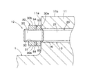
図5および図6に示すように、本実施の形態による外部連通部50は、第1ナット30に複数設けられている。そして、複数の外部連通部50が、第1ナット30のねじ孔32から放射状に延びている。より具体的には、各外部連通部50は、第1ナット30の当接面30aに設けられた、ねじ孔32から第1ナット30の外周面30bまで延びる外部連通溝53を含んでいる。複数の外部連通溝53は、第1ナット30の中心軸に対して放射状に延びている。このようにして、本実施の形態によるカップリング構造用ナットとしての第1ナット30は、カップリングボルト20に螺合するねじ孔32と、ねじ孔32から放射状に延びる複数の外部連通部50と、を有するように構成されている。
As shown in FIGS. 5 and 6, a plurality of
このように本実施の形態によれば、複数の外部連通部50が、第1ナット30に設けられて、第1ナット30のねじ孔32から放射状に延びている。このことにより、ボルト孔13内の冷却油を、ねじ孔32および外部連通部50を介して排出することができる。また、第1ナット30をカップリングボルト20に締め付けた後であっても、複数の外部連通部50のうちの1つの外部連通部50を、第1ナット30のねじ孔32から半径方向外側(第1ロータ1の中心軸に対する半径方向外側)若しくは実質的に半径方向外側に向けることができる。このため、外部連通部50を第1ナット30に設けた場合であっても、ボルト孔13内の冷却油を、遠心力を利用してスムースに排出することができる外部連通部50を容易に得ることができる。
As described above, according to the present embodiment, the plurality of
また、本実施の形態によれば、外部連通部50が、第1ナット30の当接面30aに設けられた外部連通溝53を含んでいる。このことにより、外部連通部50を、第1ナット30に設けながらもボルト孔13の第1ボルト孔部分14に近づけることができる。このため、ボルト孔13内の冷却油をスムースに排出することができる。また、外部連通部50の機械加工性を向上させることができる。
Further, according to the present embodiment, the
なお、上述した本実施の形態においては、外部連通部50は、第1ナット30の当接面30aに設けられた、ねじ孔32から延びる外部連通溝53を含んでいる例について説明した。しかしながら、このことに限られることはなく、例えば、図7に示すように、外部連通部50は、第1ナット30のねじ孔32から第1ナット30の外周面30bまで延びる外部連通孔54を含んでいてもよい。図7に示す形態では、外部連通孔54は、第1ナット30の当接面30aから離間して設けられるため、第1ナット30の当接面30aを全体的に第1フランジ11の背面11aに当接させることができ、第1ナット30の締め付けを安定化させることができる。
In the above-described embodiment, the example in which the
(第3の実施の形態)
次に、図8乃至図11を用いて、本発明の第3の実施の形態におけるカップリング構造およびカップリング構造用ナットについて説明する。
(Third embodiment)
Next, a coupling structure and a coupling structure nut according to a third embodiment of the present invention will be described with reference to FIGS.
図8乃至図11に示す第3の実施の形態においては、第1ナットに設けられたエンドカバーに、外部連通部が設けられている点が主に異なり、他の構成は、図1乃至図4に示す第1の実施の形態と略同一である。なお、図8乃至図11において、図1乃至図4に示す第1の実施の形態と同一部分には同一符号を付して詳細な説明は省略する。 The third embodiment shown in FIGS. 8 to 11 is mainly different from the end cover provided in the first nut in that an external communication portion is provided. Other configurations are the same as those in FIGS. This is substantially the same as the first embodiment shown in FIG. 8 to 11, the same parts as those of the first embodiment shown in FIGS. 1 to 4 are denoted by the same reference numerals, and detailed description thereof is omitted.
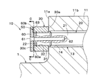
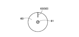
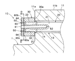
図8および図9に示すように、本実施の形態においては、カップリングボルト20の第1ねじ部22は、第1ナット30から突出しないようになっている。そして、第1ナット30の当接面30aとは反対側の面30cに、エンドカバー60が設けられている。このエンドカバー60は、エンドカバーボルト61によって、カップリングボルト20に締結されている。より具体的には、カップリングボルト20に、第1ねじ部22からボルト本体21に延びるエンドねじ孔62が設けられており、このエンドねじ孔62に、エンドカバーボルト61が螺合して締め付けられている。エンドねじ孔62は、カップリングボルト20に第1ナット30および第2ナット33を締結する際に、加熱部材や温度センサ、油圧制御器具などの器具(図示せず)を挿入するためのものであり、エンドカバー60は、このエンドねじ孔62を塞ぐためのものである。
As shown in FIGS. 8 and 9, in the present embodiment, the
本実施の形態による外部連通部50は、エンドカバー60に設けられている。より具体的には、外部連通部50は、エンドカバー60の第1ナット30の側の面(当接面60a)に設けられた、半径方向(第1ロータ1の中心軸に対する半径方向)に延びる外部連通溝63を含んでいる。この外部連通溝63は、当接面60aのうち第1ナット30のねじ孔32を塞ぐ部分からエンドカバー60の外周面60bまで延びている。
The
このように本実施の形態によれば、外部連通部50が、エンドカバー60に設けられている。このことにより、ボルト孔13内の冷却油を、ねじ孔32および外部連通部50を介して排出することができる。また、外部連通部50が、比較的小さなエンドカバー60に設けられるため、外部連通部50の機械加工性を向上させることができる。
Thus, according to the present embodiment, the
また、本実施の形態によれば、外部連通部50が、エンドカバー60の当接面60aに設けられた、半径方向に延びる外部連通溝63を含んでいる。このことにより、外部連通部50の機械加工性を向上させることができる。
Further, according to the present embodiment, the
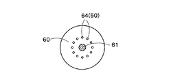
なお、上述した本実施の形態においては、外部連通部50が、エンドカバー60の当接面60aに設けられた、半径方向に延びる外部連通溝63を含んでいる例について説明した。しかしながら、このことに限られることはなく、例えば、図10および図11に示すように、外部連通部50は、軸方向に延びる外部連通孔64を含んでいてもよい。この外部連通孔64は、当接面60aのうち第1ナット30のねじ孔32を塞ぐ部分からエンドカバー60の当接面60aとは反対側の面60cまで延びている。図10および図11に示す形態では、このような外部連通部50(外部連通孔64)がエンドカバー60に複数設けられており、第1ナット30の中心軸に対する周方向に離間して形成されている。図10および図11に示す形態であっても、ボルト孔13内の冷却油を、ねじ孔32および外部連通部50を介して排出することができる。また、比較的小さなエンドカバー60に外部連通部50(外部連通孔64)を設けるため、外部連通部50の機械加工性をより一層向上させることができる。この場合、外部連通部50が設けられていない既設のエンドカバー60にも、容易に外部連通部50を追加加工で設けることができる。
In the above-described embodiment, the example in which the
以上述べた実施の形態によれば、回転時にボルト孔内に油が滞留することによって異常振動が発生することを防止できる。 According to the embodiment described above, it is possible to prevent abnormal vibration from occurring due to oil remaining in the bolt hole during rotation.
本発明のいくつかの実施形態を説明したが、これらの実施形態は、例として提示したものであり、発明の範囲を限定することは意図していない。これら新規な実施形態は、その他の様々な形態で実施されることが可能であり、発明の要旨を逸脱しない範囲で、種々の省略、置き換え、変更を行うことができる。これら実施形態やその変形は、発明の範囲や要旨に含まれるとともに、特許請求の範囲に記載された発明とその均等の範囲に含まれる。また、当然のことながら、本発明の要旨の範囲内で、これらの実施の形態を、部分的に適宜組み合わせることも可能である。 Although several embodiments of the present invention have been described, these embodiments are presented by way of example and are not intended to limit the scope of the invention. These novel embodiments can be implemented in various other forms, and various omissions, replacements, and changes can be made without departing from the scope of the invention. These embodiments and modifications thereof are included in the scope and gist of the invention, and are included in the invention described in the claims and the equivalents thereof. Moreover, as a matter of course, these embodiments can be partially combined as appropriate within the scope of the present invention.
1:第1ロータ、2:第2ロータ、10:カップリング構造、11:第1フランジ、11a:背面、12:第2フランジ、12a:背面、13:ボルト孔、20:カップリングボルト、30:第1ナット、30a:当接面、30c:面、31:ナット本体、32:ねじ孔、33:第2ナット、50:外部連通部、51:外部連通孔、52:外部連通溝、53:外部連通溝、54:外部連通孔、60:エンドカバー、60a:当接面、63:外部連通溝、64:外部連通孔 1: first rotor, 2: second rotor, 10: coupling structure, 11: first flange, 11a: back surface, 12: second flange, 12a: back surface, 13: bolt hole, 20: coupling bolt, 30 : First nut, 30a: contact surface, 30c: surface, 31: nut body, 32: screw hole, 33: second nut, 50: external communication portion, 51: external communication hole, 52: external communication groove, 53 : External communication groove, 54: external communication hole, 60: end cover, 60a: contact surface, 63: external communication groove, 64: external communication hole
Claims (11)
前記第1ロータの端部に設けられた第1フランジと、
前記第2ロータの前記第1ロータの側の端部に設けられた第2フランジと、
前記第1フランジおよび前記第2フランジを貫通するボルト孔と、
前記ボルト孔を貫通し、前記第1フランジと前記第2フランジとを締結するカップリングボルトと、
前記カップリングボルトに締め付けられたカップリング構造用ナットと、
前記ボルト孔を外部に連通した外部連通部と、
を備えた、カップリング構造。 A coupling structure for coupling the first rotor and the second rotor,
A first flange provided at an end of the first rotor;
A second flange provided at an end of the second rotor on the first rotor side;
A bolt hole penetrating the first flange and the second flange;
A coupling bolt that passes through the bolt hole and fastens the first flange and the second flange;
A coupling structure nut fastened to the coupling bolt;
An external communication portion communicating the bolt hole to the outside;
With a coupling structure.
前記外部連通部は、前記カップリング構造用ナットに複数設けられ、
複数の前記外部連通部は、前記ねじ孔から放射状に延びている、請求項1に記載のカップリング構造。 The coupling structure nut has a screw hole to be screwed into the coupling bolt,
A plurality of the external communication portions are provided on the coupling structure nut,
The coupling structure according to claim 1, wherein the plurality of external communication portions extend radially from the screw holes.
前記カップリング構造用ナットの前記第1フランジの側とは反対側の面に、エンドカバーが設けられ、
前記外部連通部は、前記エンドカバーに設けられている、請求項1に記載のカップリング構造。 The coupling structure nut includes a nut main body, and a screw hole that penetrates the nut main body and is screwed into the coupling bolt.
An end cover is provided on a surface opposite to the first flange side of the coupling structure nut,
The coupling structure according to claim 1, wherein the external communication portion is provided in the end cover.
前記カップリングボルトに螺合するねじ孔と、
前記ねじ孔から放射状に延びる複数の外部連通部と、
を備えた、カップリング構造用ナット。 Used in a coupling structure for coupling the first rotor and the second rotor, passing through a bolt hole penetrating the first flange of the first rotor and the second flange of the second rotor, the first flange and the A coupling structure nut fastened to a coupling bolt for fastening the second flange,
A screw hole screwed into the coupling bolt;
A plurality of external communication portions extending radially from the screw holes;
A coupling structure nut.
Priority Applications (1)
| Application Number | Priority Date | Filing Date | Title |
|---|---|---|---|
| JP2016081403A JP6702542B2 (en) | 2016-04-14 | 2016-04-14 | Coupling structure and nut for coupling structure |
Applications Claiming Priority (1)
| Application Number | Priority Date | Filing Date | Title |
|---|---|---|---|
| JP2016081403A JP6702542B2 (en) | 2016-04-14 | 2016-04-14 | Coupling structure and nut for coupling structure |
Publications (2)
| Publication Number | Publication Date |
|---|---|
| JP2017190839A true JP2017190839A (en) | 2017-10-19 |
| JP6702542B2 JP6702542B2 (en) | 2020-06-03 |
Family
ID=60085132
Family Applications (1)
| Application Number | Title | Priority Date | Filing Date |
|---|---|---|---|
| JP2016081403A Active JP6702542B2 (en) | 2016-04-14 | 2016-04-14 | Coupling structure and nut for coupling structure |
Country Status (1)
| Country | Link |
|---|---|
| JP (1) | JP6702542B2 (en) |
Citations (11)
| Publication number | Priority date | Publication date | Assignee | Title |
|---|---|---|---|---|
| JPS5027203U (en) * | 1973-07-09 | 1975-03-28 | ||
| JPS5438764U (en) * | 1977-08-24 | 1979-03-14 | ||
| JPS571813A (en) * | 1980-06-05 | 1982-01-07 | Akira Irie | Loosen preventing method of nut |
| US4403795A (en) * | 1980-12-09 | 1983-09-13 | Davlin Irwin H | Flange union with improved recessed seats and sealing ring |
| JPS60107611U (en) * | 1983-12-27 | 1985-07-22 | 株式会社新潟鐵工所 | bolt heat dissipator |
| JPS6159020A (en) * | 1984-08-31 | 1986-03-26 | Mitsubishi Heavy Ind Ltd | Reamer bolt clamping device |
| JPS61155601U (en) * | 1985-03-20 | 1986-09-26 | ||
| JPS62158211U (en) * | 1986-03-31 | 1987-10-07 | ||
| JPS6327712U (en) * | 1986-08-06 | 1988-02-23 | ||
| JPH02113022U (en) * | 1989-02-27 | 1990-09-10 | ||
| JP2002256807A (en) * | 2000-12-22 | 2002-09-11 | General Electric Co <Ge> | Bolted joint for rotor disk and method for reducing thermal gradient therein |
-
2016
- 2016-04-14 JP JP2016081403A patent/JP6702542B2/en active Active
Patent Citations (11)
| Publication number | Priority date | Publication date | Assignee | Title |
|---|---|---|---|---|
| JPS5027203U (en) * | 1973-07-09 | 1975-03-28 | ||
| JPS5438764U (en) * | 1977-08-24 | 1979-03-14 | ||
| JPS571813A (en) * | 1980-06-05 | 1982-01-07 | Akira Irie | Loosen preventing method of nut |
| US4403795A (en) * | 1980-12-09 | 1983-09-13 | Davlin Irwin H | Flange union with improved recessed seats and sealing ring |
| JPS60107611U (en) * | 1983-12-27 | 1985-07-22 | 株式会社新潟鐵工所 | bolt heat dissipator |
| JPS6159020A (en) * | 1984-08-31 | 1986-03-26 | Mitsubishi Heavy Ind Ltd | Reamer bolt clamping device |
| JPS61155601U (en) * | 1985-03-20 | 1986-09-26 | ||
| JPS62158211U (en) * | 1986-03-31 | 1987-10-07 | ||
| JPS6327712U (en) * | 1986-08-06 | 1988-02-23 | ||
| JPH02113022U (en) * | 1989-02-27 | 1990-09-10 | ||
| JP2002256807A (en) * | 2000-12-22 | 2002-09-11 | General Electric Co <Ge> | Bolted joint for rotor disk and method for reducing thermal gradient therein |
Also Published As
| Publication number | Publication date |
|---|---|
| JP6702542B2 (en) | 2020-06-03 |
Similar Documents
| Publication | Publication Date | Title |
|---|---|---|
| US7374402B2 (en) | Fastening arrangement for an impeller on a shaft | |
| US11435264B2 (en) | Probe device capable of suppressing damage while also suppressing increase in labor for mounting work | |
| US20160377089A1 (en) | Rotor for a Turbocharger Device, Turbocharger Device Having a Rotor, and Shaft for a Rotor of said Type | |
| US20150226233A1 (en) | Impeller, and rotating machine provided with same | |
| US10012390B2 (en) | Combustion chamber of a gas turbine with bolted combustion chamber head | |
| ES2955108T3 (en) | axial flow compressor | |
| US20140286770A1 (en) | Mechanical system for a turbine engine, turbine engine, and method for attaching a mechanical system within a turbine engine | |
| US8047781B2 (en) | Bolt assembly for steam turbine engines and method of assembling the same | |
| JP2011220264A (en) | Centrifugal compressor | |
| JP2010096113A (en) | Impeller fastening structure | |
| JP2008298287A (en) | Fixing system for rotor of rotating fluid machine | |
| JP6367363B2 (en) | Coupling device for connecting the clutch to the turbine train | |
| KR101925234B1 (en) | Fixing device, rotary machine, manufacturing method of rotary machine, assembly method and separation method | |
| KR102902189B1 (en) | Turbine casing including a low-stress connecting flange and exhaust-gas turbine having such turbine casing | |
| JP2017190839A (en) | Coupling structure and coupling structure nut | |
| JP5669633B2 (en) | Sensor mounting structure | |
| US20150118031A1 (en) | System and a method of installing a tip shroud ring in turbine disks | |
| KR102513733B1 (en) | Coupling device | |
| JP2009174358A (en) | Supercharger | |
| US9856887B2 (en) | Rotor of a supercharging device | |
| JP2013213475A (en) | Balance adjusting tool for rotary machine | |
| RU2541623C1 (en) | Resilient support of turbomachine rotor | |
| US20110243727A1 (en) | Steam turbine half shell joint assembly | |
| EP3263851B1 (en) | Turbine assembly | |
| US20130216385A1 (en) | Grease passage in flanged bearings |
Legal Events
| Date | Code | Title | Description |
|---|---|---|---|
| A711 | Notification of change in applicant |
Free format text: JAPANESE INTERMEDIATE CODE: A712 Effective date: 20171130 |
|
| A711 | Notification of change in applicant |
Free format text: JAPANESE INTERMEDIATE CODE: A711 Effective date: 20171201 |
|
| A621 | Written request for application examination |
Free format text: JAPANESE INTERMEDIATE CODE: A621 Effective date: 20190121 |
|
| A977 | Report on retrieval |
Free format text: JAPANESE INTERMEDIATE CODE: A971007 Effective date: 20191111 |
|
| A131 | Notification of reasons for refusal |
Free format text: JAPANESE INTERMEDIATE CODE: A131 Effective date: 20191115 |
|
| A521 | Request for written amendment filed |
Free format text: JAPANESE INTERMEDIATE CODE: A523 Effective date: 20191217 |
|
| TRDD | Decision of grant or rejection written | ||
| A01 | Written decision to grant a patent or to grant a registration (utility model) |
Free format text: JAPANESE INTERMEDIATE CODE: A01 Effective date: 20200403 |
|
| A61 | First payment of annual fees (during grant procedure) |
Free format text: JAPANESE INTERMEDIATE CODE: A61 Effective date: 20200424 |
|
| R150 | Certificate of patent or registration of utility model |
Ref document number: 6702542 Country of ref document: JP Free format text: JAPANESE INTERMEDIATE CODE: R150 |