JP2017190826A - Two-way valve and water heater - Google Patents
Two-way valve and water heater Download PDFInfo
- Publication number
- JP2017190826A JP2017190826A JP2016080072A JP2016080072A JP2017190826A JP 2017190826 A JP2017190826 A JP 2017190826A JP 2016080072 A JP2016080072 A JP 2016080072A JP 2016080072 A JP2016080072 A JP 2016080072A JP 2017190826 A JP2017190826 A JP 2017190826A
- Authority
- JP
- Japan
- Prior art keywords
- shape memory
- memory alloy
- end side
- pipe
- hot water
- Prior art date
- Legal status (The legal status is an assumption and is not a legal conclusion. Google has not performed a legal analysis and makes no representation as to the accuracy of the status listed.)
- Pending
Links
Images

Landscapes
- Heat-Pump Type And Storage Water Heaters (AREA)
- Temperature-Responsive Valves (AREA)
Abstract
【課題】形状記憶合金バネを使用した二方弁であって、形状記憶合金バネのバネ定数の管理を緩やかにして安価な構造とする。
【解決手段】上下方向を向いた水路21を有する筒体20と、両端を上下方向に向けて筒体20内に収容され、下端側が位置固定に保持されて上端側が上下方向変位可能とされた形状記憶合金バネ22と、筒体20内に上下方向移動可能に設けられ、上端側が形状記憶合金バネ22の上端側に係止され、下端側に重り25が係止された摺動体23と、摺動体23に係止され、形状記憶合金バネ22の伸縮により水路21を閉止する閉止位置と水路21を開放する開放位置とに移動する弁部26と、を有する。
【選択図】図6A two-way valve using a shape memory alloy spring, which is made inexpensive by loosely managing the spring constant of the shape memory alloy spring.
SOLUTION: A cylinder body 20 having a water channel 21 facing in the vertical direction and the both ends of the cylinder body 20 are accommodated in the cylinder body 20 so that the lower end side is held fixed and the upper end side can be displaced in the vertical direction. A shape memory alloy spring 22, a slide body 23 provided in the cylinder 20 so as to be movable in the vertical direction, an upper end side locked to the upper end side of the shape memory alloy spring 22, and a weight 25 locked to the lower end side; It has a valve portion 26 that is locked to the sliding body 23 and moves to a closing position for closing the water passage 21 and an opening position for opening the water passage 21 by expansion and contraction of the shape memory alloy spring 22.
[Selection] Figure 6
Description
本発明の実施形態は、湯水の流れを切り換える二方弁及びその二方弁を使用した給湯装置に関する。 Embodiments of the present invention relate to a two-way valve that switches the flow of hot water and a hot water supply device that uses the two-way valve.
従来、湯水が流れる水路中に、流れる湯水の温度によりその湯水の流れを切り換える二方弁を設けた様々な装置が知られている。このような二方弁の一例としては、下記特許文献1に記載されているように、温度により伸縮する形状記憶合金バネを用いたものが提案されている。
2. Description of the Related Art Conventionally, various devices are known in which a two-way valve for switching the flow of hot water according to the temperature of flowing hot water is provided in a water channel through which hot water flows. As an example of such a two-way valve, as described in
下記特許文献1に記載されている二方弁は、摺動可能な弁体を一方向に付勢する形状記憶合金バネと、弁体を形状記憶合金バネによる付勢方向と反対方向に付勢するバイアスバネとを有している。冷水が形状記憶合金バネに接触して流れる場合には、形状記憶合金バネが縮むとともに形状記憶合金のバネ定数が小さくなる。一方、温水が形状記憶合金に接触して流れる場合には、形状記憶合金が伸びるとともに形状記憶合金バネのバネ定数が大きくなる。そして、伸縮した形状記憶合金バネとバイアスバネとがバランスをとる位置に弁体が摺動し、弁体が摺動して位置を変えることにより、冷水又は温水の流れが切り換えられる。
The two-way valve described in the following
しかしながら、上述した特許文献1に記載された二方弁では、形状記憶合金バネのバネ定数とバイアスバネのバネ定数とにより弁体の摺動位置が決定されるため、形状記憶合金バネとバイアスバネとのバネ定数とを高精度に管理する必要がある。しかし、これらのバネ定数のバラツキを高精度に管理することは難しく、形状記憶合金バネとバイアスバネとのバネ定数を高精度に管理するためには多大なコストを必要とし、実用化に至っていないことが現状である。
However, in the two-way valve described in
本発明の実施形態の目的は、形状記憶合金バネを使用した二方弁であって形状記憶合金バネのバネ定数の管理を緩やかにして安価な構造とすることができる二方弁、及びその二方弁を用いた給湯装置を提供することである。 An object of an embodiment of the present invention is a two-way valve using a shape memory alloy spring, which can be a low-cost structure with a moderate control of the spring constant of the shape memory alloy spring, and two of them. It is providing the hot-water supply apparatus using a way valve.
実施形態の二方弁は、上下方向を向いた水路を有する筒体と、両端を上下方向に向けて筒体内に収容され、下端側が位置固定に保持されて上端側が上下方向変位可能とされた形状記憶合金バネと、筒体内に上下方向移動可能に設けられ、上端側が形状記憶合金バネの上端側に係止され、下端側に重りが係止された摺動体と、摺動体に係止され、形状記憶合金バネの伸縮により水路を閉止する閉止位置と水路を開放する開放位置とに移動する弁部と、を有する。 The two-way valve of the embodiment is accommodated in the cylinder having a water channel facing the vertical direction and both ends in the vertical direction, the lower end side is held fixed, and the upper end side can be displaced in the vertical direction A shape memory alloy spring, a slide body provided in the cylinder body so as to be movable in the vertical direction, an upper end side locked to the upper end side of the shape memory alloy spring, and a weight locked to the lower end side; And a valve portion that moves between a closed position for closing the water channel and an open position for opening the water channel by expansion and contraction of the shape memory alloy spring.
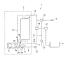
以下、一実施形態を図面に基づいて説明する。図1は、給湯システム1を示しており、この給湯システム1は、冷水を沸き上げて沸上げた温水を貯える給湯装置2、洗面所や台所に設けられて貯えられた温水が給湯される給湯栓3や浴槽4等により構成されている。
Hereinafter, an embodiment will be described with reference to the drawings. FIG. 1 shows a hot
給湯装置2は、冷水を沸き上げて温水にする加熱手段であるヒートポンプ5と、ヒートポンプ5で沸き上げられた温水を貯えるタンク6とを有している。
The hot
ヒートポンプ5は、冷媒を用いて熱交換を行う装置であり、入口部5aから流入した冷水を沸き上げて温水とし、その温水を出口部5bからタンク6に向けて流出させるように構成されている。
The
タンク6は、下側に冷水が貯えられるとともに上側に沸き上げられた温水が貯えられるようになっている。タンク6の下部には、水道水(冷水)が供給される給水管7と、タンク6内の湯水(冷水又は温水)が排水される排水管8と、タンク6内の冷水をヒートポンプ5に導く第1配管9とが接続されている。第1配管9のヒートポンプ5側の端部は、ヒートポンプ5の入口部5aに接続されている。給水管7の途中には、減圧弁10と圧力逃し弁11とが設けられている。排水管8の排水側端部には、排水栓12が設けられている。
The tank 6 is configured so that cold water is stored on the lower side and hot water boiled on the upper side is stored. Below the tank 6, a water supply pipe 7 to which tap water (cold water) is supplied, a
タンク6の上部には、ヒートポンプ5で沸き上げられた温水をタンク6内に導く第2配管13と、タンク6内に貯えられている温水を給湯栓3や浴槽4に導く給湯管14とが接続されている。第2配管13のヒートポンプ5側の端部は、ヒートポンプ5の出口部5bに接続されている。給湯栓3に接続されている給湯管14の途中には、タンク6内からの温水と給水管7からの水道水とを混合して温水の温度調節を行う給湯用混合弁15が設けられている。浴槽4に接続されている給湯管14の途中には、タンク6内からの温水と給水管7からの水道水とを混合して温水の温度調節を行う浴槽用混合弁16と、浴槽4への給湯状態のオン・オフを切り換える浴槽給湯用電動弁17とが設けられている。
In the upper part of the tank 6, there are a
第2配管13と第1配管9との間には、戻し配管18が接続されている。戻し配管18の途中には、第2配管13内を流れる湯水の温度が設定温度以上である場合に閉弁されてその湯水をタンク6内に導くとともに、第2配管13内を流れる湯水の温度が設定温度未満である場合に開弁されその湯水を戻し配管18を通して第1配管9に導く二方弁19が設けられている。
A
また、第1配管9の戻し配管18との接続部とヒートポンプ5との接続部の途中には、湯水を循環させる循環ポンプ30が設けられている。この循環ポンプ30の運転により第1配管9及び第2配管13を介して、タンク6内の湯水をヒートポンプ5との間で循環させることができる。
Further, a circulating
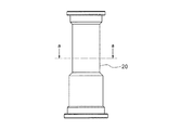
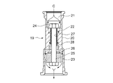
二方弁19は、図2に示すような筒体20を有し、この筒体20の内部には筒体20の両端を連通する水路21が形成されている。また、筒体20の内部には、後述する図5ないし図7に示すような、形状記憶合金バネ22、先端部が雄ネジに形成された六角ボルト状の摺動体23、摺動体23の先端部の雄ネジに螺合されるナット24、摺動体23に固定される重り25と弁部である弁部パッキン26が収容されている。筒体20の外形形状は、中央部が細く両端部が太い形状に形成されている。また、筒体20の両端部は異なる形状とされている。
The two-
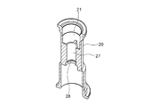
筒体20の内部の中央部には、図3、4及び図6、7に示すように、水路21の中央部に位置してバネ収容スペース27が形成され、このバネ収容スペース27内に形状記憶合金バネ22が収容されている。バネ収容スペース27の下端側内周部には、バネ収容スペース27の内周側に向けてフランジ状に張り出し、収容した形状記憶合金バネ22の下端側を位置固定に保持する保持部28が形成されている。これらの水路21とバネ収容スペース27とは、二方弁19を戻し配管18の途中の取付位置に取付けた場合に上下方向を向くように形成されている。
As shown in FIGS. 3, 4, 6, and 7, a spring
筒体20のバネ収容スペース27内には、図6及び図7に示すように、両端を上下方向に向けるとともに上下方向に伸縮可能である形状記憶合金バネ22が収容されている。形状記憶合金バネ22は、下端側が保持部28により保持され、伸縮時には上端側が上下方向変位可能とされている。
As shown in FIGS. 6 and 7, a shape
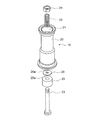
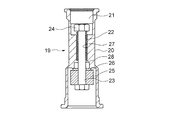
形状記憶合金バネ22の内側には、摺動体23が同軸状に配置されるとともにこの摺動体23は上下方向摺動可能に設けられている。摺動体23の上端部であって形状記憶合金バネ22より上方に突出した部分にはナット24が螺合され、摺動体23の下端側であって形状記憶合金バネ22より下方に突出した部分には重り25が固定されている。摺動体23への重り25の固定は、重り25の中央部に形成された嵌合孔25aに摺動体23を嵌合させることにより行われている。そして、摺動体23の下端側に重り25が固定され、摺動体23の上端側にナット24が螺合されることにより、摺動体23の上端側が形状記憶合金バネ22の上端側に固定された状態となり、形状記憶合金バネ22には重り25の荷重が常時下向きに作用した状態となっている。
Inside the shape
また、摺動体23には、重り25の上方位置に弁部パッキン26が固定されている。摺動体23への弁部パッキン26の固定は、弁部パッキン26の中央部に形成された嵌合孔26aに摺動体23を嵌合させることにより行われている。
Further, the valve unit packing 26 is fixed to the sliding
ここで、摺動体23の上端側が形状記憶合金バネ22の上端側に固定され、摺動体23の下端側に重り25と弁部パッキン26とが固定されることにより、形状記憶合金バネ22の伸縮に伴い摺動体23が上下方向に摺動し、摺動体23の摺動に伴って重り25と弁部パッキン26とが上下方向に摺動するようになっている。弁部パッキン26の外形寸法は、バネ収容スペース27の下方位置におけるける水路21の径寸法より大きく形成されており、摺動体23が最上方位置に摺動した場合に弁部パッキン26がバネ収容スペース27の下方位置で水路21を閉止する閉止位置に移動し、摺動体23が下方へ摺動した場合に弁部パッキン26がバネ収容スペース27の下方位置で水路21を開放する開放位置に移動するようになっている。
Here, the upper end side of the sliding
図6は、二方弁19が開弁されている状態を示している。この開弁時には、形状記憶合金バネ22が縮むとともにバネ定数が小さくなっており、重り25の荷重により摺動体23が下方に摺動し、ナット24がバネ収容スペース27の上端側縁部に当接することにより摺動体23が最下方位置で位置固定されている。この場合、弁部パッキン26は、水路21を開放する位置に位置している。
FIG. 6 shows a state where the two-
図7は、二方弁19が閉弁されている状態を示している。この閉弁時には、形状記憶合金バネ22が伸びるとともにバネ定数が大きくなっており、下端側を保持部28により保持されている形状記憶合金バネ22の上端側が上方に延びている。形状記憶合金バネ22の上端側が上方に伸びることにより、摺動体23が弁部パッキン26や重り25と共に上方に摺動し、弁部パッキン26が水路21を閉止する位置に位置している。
FIG. 7 shows a state where the two-
このような構成において、ヒートポンプ5を駆動すると、タンク6内の下部に貯えられている冷水が第1配管9内を矢印Aで示す方向に流れ、ヒートポンプ5内に導かれる。ヒートポンプ5内に導かれた冷水は、冷媒を利用した熱交換により沸き上げられて温水となり、第2配管13内を矢印Bで示す方向に流れ、タンク6内に導かれる。これにより、タンク6内の上部には温水が貯えられ、タンク6内の下部には冷水が貯えられた状態となる。
In such a configuration, when the
第1配管9と第2配管13とを接続する戻し配管18の途中には、第2配管13内を流れる温水の温度により開閉される二方弁19が設けられている。この二方弁19は、第2配管13内を流れる温水の温度が設定温度以上である場合には閉弁され、温水は第2配管13内を矢印B方向に流れ、タンク6内に導かれる。一方、第2配管13内を流れる温水の温度が設定温度未満である場合には二方弁19が開弁され、第2配管13内を流れる温水は矢印Cで示すように戻し配管18内を通って第1配管9内に流入し、再びヒートポンプ5内に導かれる。
In the middle of the
ここで、循環ポンプ30をヒートポンプ5と二方弁19との間に構成される流路に設け、戻し配管18の流路を短くし第2配管13と二方弁19との間の配管距離を短くすることで、後述する二方弁19の温度に応じて弁の開閉を行う応答性を向上させることができる。
Here, the
二方弁19は温度により伸縮する形状記憶合金バネ22を利用して開閉される弁であり、この二方弁19の開閉動作について以下に説明する。
The two-
図6は、第2配管13内を流れる温水の温度が設定温度未満であるため、二方弁19が開弁されている状態を示している。形状記憶合金バネ22は第2配管13内を流れる温水に浸されており、この温水が設定温度未満である場合には形状記憶合金バネ22は縮んでいる。形状記憶合金バネ22が縮むことにより、形状記憶合金バネ22の上端側に固定されている摺動体23は重り25の荷重により下方へ摺動し、弁部パッキン26も摺動体23と一体に下方へ摺動する。この摺動に伴い、弁部パッキン26は水路21を開放する位置に移動する。これにより、第2配管13と第1配管9とが戻し配管18を介して連通された状態となる。第2配管13と第1配管9とが戻し配管18を介して連通されると、第2配管13内を流れる温水は水路抵抗の少ない第1配管9に流れるようになり、水路21を通って図1及び図6に示す矢印C方向の流れが発生する。戻し配管18内を通って第1配管9内に流入した温水は、再びヒートポンプ5内に導かれ、沸き上げられる。
FIG. 6 shows a state where the two-
図7は、第2配管13内を流れる温水の温度が設定温度以上であるため、二方弁19が閉弁されている状態を示している。形状記憶合金バネ22は第2配管13内を流れる温水に浸されており、この温水の温度が設定温度以上である場合には形状記憶合金バネ22は伸びる。形状記憶合金バネ22が伸びることにより、下端側を保持部28に保持されている形状記憶合金バネ22は上方側が上方へ移動する。形状記憶合金バネ22の上方側が上方へ移動することにより、上端側を形状記憶合金バネ22の上端側に固定されている摺動体23が上方へ摺動し、重り25と弁部パッキン26とが一体に上方に摺動する。そして、摺動体23が最上方位置に摺動した場合に、弁部パッキン26が水路21を閉止する位置に移動する。これにより、二方弁19が閉弁され、第2配管13内を流れる設定温度以上に沸き上げられた温水はタンク6内の上部に貯えられる。
FIG. 7 shows a state where the two-
ここで、形状記憶合金バネ22を使用した二方弁19は、第2配管13内を流れる温水の温度が設定温度未満である場合には、形状記憶合金バネ22が縮んでバネ定数が小さくなるとともに重り25の荷重により摺動体23が下方に摺動し、摺動体23に固定されている弁部パッキン26が水路21を開放する位置に移動する。一方、第2配管13内を流れる温水の温度が設定温度以上である場合には、形状記憶合金バネ22が伸びてバネ定数が大きくなるとともに摺動体23が上方に摺動し、摺動体23が最上方位置に摺動した場合しに弁部パッキン26が水路21を閉止する。従って、この二方弁19では、使用する形状記憶合金バネ22では、伸縮に伴って弁部パッキン26を水路21を開閉する位置に移動させることができればよく、バネ定数を高精度に管理する必要はない。これにより、形状記憶合金バネ22及び形状記憶合金バネ22を使用した二方弁19を安価な構造とすることができ、しかも、温水の温度に応じた温水の流れの切り換えを確実に行うことができる。
Here, in the two-
さらに、形状記憶合金バネ22の伸縮方向に荷重を加える重り25の設置に関しては、摺動体23を形状記憶合金バネ22の内側に同軸状に挿通させ、摺動体23の上端側を形状記憶合金バネ22の上端側に固定するとともに摺動体23の下端側に重り25を固定している。このため、重り25の設置のために必要となるスペースが小さくなり、二方弁19の小型化及び二方弁19の設置スペースの省スペース化を図ることができる。
Further, regarding the installation of the
また、二方弁19の外郭をなす筒体20は、両端部の形状が異なっているため、この二方弁19を戻し配管18の途中に取付ける場合、逆向きに取付けることを防止することができる。
Moreover, since the
なお、本実施の形態では加熱手段としてヒートポンプ5を例に挙げて説明したが、加熱手段としてはヒートポンプ5に代えて燃焼式ボイラや電熱式加熱器を用いてもよい。
In the present embodiment, the
以上、本発明の実施形態を説明したが、この実施形態は、例として提示したものであり、発明の範囲を限定することは意図していない。この実施形態は、その他の様々な形態で実施されることが可能であり、発明の要旨を逸脱しない範囲で、種々の省略、置き換え、変更を行うことができる。この実施形態やその変形は、発明の範囲や要旨に含まれると同様に、特許請求の範囲に記載された発明とその均等の範囲に含まれるものである。 As mentioned above, although embodiment of this invention was described, this embodiment is shown as an example and is not intending limiting the range of invention. This embodiment can be implemented in various other forms, and various omissions, replacements, and changes can be made without departing from the spirit of the invention. This embodiment and its modifications are included in the scope of the present invention and the gist thereof, and are also included in the invention described in the claims and the equivalent scope thereof.
5…ヒートポンプ(加熱手段)、5a…入口部、5b…出口部、9…第1配管、13…第2配管、18…戻し配管、19…二方弁、20…筒体、21…水路、22…形状記憶合金バネ、23…摺動体、25…重り、26…弁部パッキン(弁部)、30…循環ポンプ
DESCRIPTION OF
Claims (5)
両端を上下方向に向けて前記筒体内に収容され、下端側が位置固定に保持されて上端側が上下方向変位可能とされた形状記憶合金バネと、
前記筒体内に上下方向移動可能に設けられ、上端側が前記形状記憶合金バネの上端側に係止され、下端側に重りが係止された摺動体と、
前記摺動体に係止され、前記形状記憶合金バネの伸縮により前記水路を閉止する閉止位置と前記水路を開放する開放位置とに移動する弁部と、
を有することを特徴とする二方弁。 A cylinder having a water channel facing in the vertical direction;
A shape memory alloy spring that is housed in the cylinder with both ends facing up and down, the lower end side is held fixed and the upper end side is vertically displaceable,
A sliding body provided in the cylinder body so as to be movable in the vertical direction, the upper end side being locked to the upper end side of the shape memory alloy spring, and the weight being locked to the lower end side;
A valve portion that is locked to the sliding body and moves to a closed position that closes the water channel and an open position that opens the water channel by expansion and contraction of the shape memory alloy spring;
A two-way valve characterized by comprising:
湯水を貯えるタンクと、
前記タンクの下部と前記加熱手段の入口部との間に設けられた第1配管と、
前記加熱手段の出口部と前記タンクの上部との間に設けられた第2配管と、
前記第1配管と前記第2配管との間に設けられた戻し配管と、
前記戻し配管の途中に設けられ、前記第2配管内を流れる湯水の温度が設定温度以上である場合に閉弁されてその湯水を前記タンク内に導くとともに、前記第2配管内を流れる湯水の温度が設定温度未満である場合に開弁されその湯水を前記戻し配管を通して前記第1配管に導く二方弁と、
を有し、
前記二方弁は、
前記戻し配管の途中に設けられて上下方向を向いた水路を有する筒体と、
両端を上下方向に向けて前記筒体内に収容され、下端側が位置固定に保持されて上端側が上下方向変位可能とされた形状記憶合金バネと、
前記筒体内に上下方向摺動可能に設けられ、上端側が前記形状記憶合金バネの上端側に係止され、下端側に重りが係止された摺動体と、
前記摺動体に係止され、前記形状記憶合金バネの伸縮により前記水路を閉止する閉止位置と前記水路を開放する開放位置とに移動する弁部と、
を有することを特徴とする給湯装置。 Heating means for boiling cold water;
A tank for storing hot water,
A first pipe provided between the lower part of the tank and the inlet of the heating means;
A second pipe provided between the outlet of the heating means and the upper part of the tank;
A return pipe provided between the first pipe and the second pipe;
When the temperature of the hot water flowing in the second pipe is equal to or higher than a set temperature, the valve is closed to guide the hot water into the tank and the hot water flowing in the second pipe. A two-way valve that opens when the temperature is lower than a set temperature and guides the hot water to the first pipe through the return pipe;
Have
The two-way valve is
A cylindrical body having a water channel provided in the middle of the return pipe and facing the vertical direction;
A shape memory alloy spring that is housed in the cylinder with both ends facing up and down, the lower end side is held fixed and the upper end side is vertically displaceable,
A sliding body provided in the cylinder so as to be slidable in the vertical direction, the upper end side being locked to the upper end side of the shape memory alloy spring, and the weight being locked to the lower end side;
A valve portion that is locked to the sliding body and moves to a closed position that closes the water channel and an open position that opens the water channel by expansion and contraction of the shape memory alloy spring;
A hot water supply apparatus characterized by comprising:
Priority Applications (1)
| Application Number | Priority Date | Filing Date | Title |
|---|---|---|---|
| JP2016080072A JP2017190826A (en) | 2016-04-13 | 2016-04-13 | Two-way valve and water heater |
Applications Claiming Priority (1)
| Application Number | Priority Date | Filing Date | Title |
|---|---|---|---|
| JP2016080072A JP2017190826A (en) | 2016-04-13 | 2016-04-13 | Two-way valve and water heater |
Publications (1)
| Publication Number | Publication Date |
|---|---|
| JP2017190826A true JP2017190826A (en) | 2017-10-19 |
Family
ID=60085853
Family Applications (1)
| Application Number | Title | Priority Date | Filing Date |
|---|---|---|---|
| JP2016080072A Pending JP2017190826A (en) | 2016-04-13 | 2016-04-13 | Two-way valve and water heater |
Country Status (1)
| Country | Link |
|---|---|
| JP (1) | JP2017190826A (en) |
Cited By (2)
| Publication number | Priority date | Publication date | Assignee | Title |
|---|---|---|---|---|
| CN108036061A (en) * | 2018-01-31 | 2018-05-15 | 以凡泰行(深圳)实业有限公司 | One kind is without electric control temperature bathtub |
| CN114087783A (en) * | 2020-07-29 | 2022-02-25 | 青岛经济技术开发区海尔热水器有限公司 | Energy storage type electric water heater |
-
2016
- 2016-04-13 JP JP2016080072A patent/JP2017190826A/en active Pending
Cited By (3)
| Publication number | Priority date | Publication date | Assignee | Title |
|---|---|---|---|---|
| CN108036061A (en) * | 2018-01-31 | 2018-05-15 | 以凡泰行(深圳)实业有限公司 | One kind is without electric control temperature bathtub |
| CN114087783A (en) * | 2020-07-29 | 2022-02-25 | 青岛经济技术开发区海尔热水器有限公司 | Energy storage type electric water heater |
| CN114087783B (en) * | 2020-07-29 | 2023-04-18 | 青岛经济技术开发区海尔热水器有限公司 | Energy storage type electric water heater |
Similar Documents
| Publication | Publication Date | Title |
|---|---|---|
| CN101784974B (en) | Valve element and thermostatic control device for controlling a mass flow | |
| WO2016173333A1 (en) | Cold-hot water separation valve | |
| JP2017190826A (en) | Two-way valve and water heater | |
| CN115023680B (en) | Device for controlling the flow of fluids | |
| CN108474486A (en) | Fluid control valve assembly for hot water mixing taps | |
| US9581336B2 (en) | Thermostat | |
| US2101338A (en) | Temperature relief valve device | |
| RU2315247C1 (en) | Safety device for water-heating system (variants) | |
| DK2217985T3 (en) | Thermostat valve actuator | |
| KR101394857B1 (en) | A water saving system | |
| GB2112907A (en) | Valve and system incorporating same | |
| JP2009121584A (en) | Temperature control valve for drainage | |
| US6820637B1 (en) | Temperature control check valve for water heater | |
| GB2522464A (en) | A thermostatic flow valve for use in water heating systems | |
| US10139129B2 (en) | Water heater having thermal displacement conduit | |
| JP6320793B2 (en) | Temperature control valve | |
| JP6379026B2 (en) | Bath circulation channel switching device | |
| ITMI20120439A1 (en) | SANITARY WATER FLOW REGULATOR AND HYDRAULIC GROUP INCORPORATING THE SAME | |
| JP2016217571A (en) | Valve device and hot water storage type hot water supply device | |
| US2248807A (en) | Pressure relief valve | |
| US761402A (en) | Thermostat and reversing-valve. | |
| US1235508A (en) | Heating system. | |
| US2736498A (en) | Gas fired storage water heater | |
| KR20130076184A (en) | A water saving system | |
| CN201014743Y (en) | Water tank of heat pump water heater with constant temperature equipment |