JP2017190108A - Molded ceiling material for vehicles - Google Patents
Molded ceiling material for vehicles Download PDFInfo
- Publication number
- JP2017190108A JP2017190108A JP2016082359A JP2016082359A JP2017190108A JP 2017190108 A JP2017190108 A JP 2017190108A JP 2016082359 A JP2016082359 A JP 2016082359A JP 2016082359 A JP2016082359 A JP 2016082359A JP 2017190108 A JP2017190108 A JP 2017190108A
- Authority
- JP
- Japan
- Prior art keywords
- ceiling material
- vehicle
- width direction
- material body
- vehicle width
- Prior art date
- Legal status (The legal status is an assumption and is not a legal conclusion. Google has not performed a legal analysis and makes no representation as to the accuracy of the status listed.)
- Pending
Links
Images


Abstract
Description
本発明は、サンルーフを有する車両におけるルーフパネルの車室内側に設けられた車両用成形天井材に関する。 The present invention relates to a molded ceiling material for a vehicle provided on a vehicle interior side of a roof panel in a vehicle having a sunroof.
従来より、自動車等の車両におけるルーフパネルの車室内側には、当該車室内に面するパネル状の天井材本体を有する車両用成形天井材が配設され、上記車両にサンルーフが設けられている場合、上記天井材本体の上記サンルーフに対応する位置には、開口部が形成されている。 Conventionally, on a vehicle interior side of a roof panel in a vehicle such as an automobile, a molded ceiling material for a vehicle having a panel-like ceiling material body facing the vehicle interior is disposed, and a sunroof is provided in the vehicle. In this case, an opening is formed at a position corresponding to the sunroof of the ceiling material body.
ところで、上記天井材本体の開口部周りにおける車幅方向両側部分は幅が狭いので、上記天井材本体の他の部分に比べて剛性が低い。したがって、例えば、車両用成形天井材を搬送する際に、上記天井材本体の開口部周りにおける車幅方向両側部分を作業者や作業ロボットが把持して搬送しようとすると、当該把持部分に大きな荷重が加わってしまい、最悪の場合、変形やひび割れが発生して上記車両用成形天井材が不良品となってしまうおそれがある。 By the way, since the width of the both sides in the vehicle width direction around the opening of the ceiling material body is narrow, the rigidity is lower than the other parts of the ceiling material body. Therefore, for example, when a molded ceiling material for a vehicle is transported, if an operator or work robot grips and transports both sides in the vehicle width direction around the opening of the ceiling material body, a large load is applied to the gripped portion. In the worst case, deformation and cracking may occur, and the molded ceiling material for a vehicle may become a defective product.
これを回避するために、例えば、特許文献1では、天井材本体の車室外側表面における開口部周りの車幅方向両側部分に車両前後方向に延びる樹脂製補強リブをホットメルト接着剤で取り付けていて、当該補強リブによって上記天井材本体の開口部周りにおける車幅方向両側部分の剛性を高めている。
In order to avoid this, for example, in
しかし、特許文献1のように上記天井材本体の開口部周りにおける車幅方向両側部分に補強リブをホットメルト接着剤で取り付けると、一般的に、発泡ウレタン材や不織布等からなる天井材本体と樹脂材からなる補強リブとでは、熱膨張係数が異なるために使用環境によっては天井材本体にシワが発生してしまうおそれがある。
However, when the reinforcing ribs are attached with hot melt adhesive to both sides in the vehicle width direction around the opening of the ceiling material body as in
また、剛性を高めるために補強リブを天井材本体の広い範囲に亘って取り付けると、剛性は高くなるものの車両用成形天井材の全体が重くなってしまう。さらには、補強リブを樹脂で形成するとともに、当該補強リブを天井材本体にホットメルト接着剤を用いて取り付ける作業は部品コスト及び製造コストの両方が嵩んでしまう。 Further, if the reinforcing ribs are attached over a wide range of the ceiling material main body in order to increase the rigidity, the entire molded ceiling material for the vehicle becomes heavy although the rigidity is increased. Furthermore, the work of attaching the reinforcing rib to the ceiling material body using a hot melt adhesive while forming the reinforcing rib with resin increases both the component cost and the manufacturing cost.
本発明は斯かる点に鑑みてなされたものであり、その目的とするところは、サンルーフ用の開口部周りの剛性を高めながらシワの発生を防ぎ、しかも、軽量で低コストな車両用成形天井材を提供することにある。 The present invention has been made in view of such a point, and the object of the present invention is to prevent the formation of wrinkles while increasing the rigidity around the opening for the sunroof, and is lightweight and low-cost molded ceiling for vehicles. To provide materials.
上記の目的を達成するために、本発明は、天井材本体の車室外側表面にホットメルト接着剤層を形成するようにしたことを特徴とする。 In order to achieve the above object, the present invention is characterized in that a hot melt adhesive layer is formed on the exterior surface of the ceiling material body on the passenger compartment.
具体的には、サンルーフを有する車両のルーフパネル車室内側に配設され、上記サンルーフに対応する開口部が形成されたパネル状の天井材本体を有する車両用成形天井材において、次のような解決手段を講じた。 Specifically, in a molded ceiling material for a vehicle having a panel-shaped ceiling material body that is disposed on the vehicle interior side of a roof panel of a vehicle having a sunroof and that has an opening corresponding to the sunroof, A solution was taken.
すなわち、第1の発明では、上記天井材本体の車室外側表面における開口部周りの車幅方向両側部分は、ホットメルト接着剤を波状又はジグザグに折り返しながら車両前後方向又は車幅方向に沿って塗布することにより形成された接着剤塗布層を有することを特徴とする。 That is, in the first invention, the both sides in the vehicle width direction around the opening on the outer surface of the vehicle interior of the ceiling material body are along the vehicle front-rear direction or the vehicle width direction while folding the hot melt adhesive into a wave shape or zigzag. It has the adhesive application layer formed by apply | coating.
第2の発明では、第1の発明において、上記接着剤塗布層の各折り返し部分は、平面視で鋭角をなすV字状をなしていることを特徴とする。 According to a second aspect, in the first aspect, each folded portion of the adhesive application layer has a V shape that forms an acute angle in plan view.
第3の発明では、第2の発明において、車幅方向に沿ってジグザグに折り返された形状をなしていることを特徴とする。 The third invention is characterized in that, in the second invention, it is shaped in a zigzag manner along the vehicle width direction.
第1の発明では、天井材本体の車室外側表面における開口部周りの車幅方向両側部分に接着剤塗布層がバランス良く配置されるので、当該部分のあらゆる方向に対する剛性を高めることができる。また、天井材本体の車室外側表面における開口部周りの車幅方向両側部分において、接着剤塗布層の無い部分が車両前後方向又は車幅方向に所定間隔に設けられるので、天井材本体の熱膨張係数と異なる熱膨張係数の部分が少なくなるとともに偏って配置されないので天井材本体にシワが発生し難い。さらには、天井材本体の開口部周りにおける車幅方向両側部分の剛性を高めるために接着剤を必要最小限の塗布量しか用いないので、特許文献1のように補強リブを用意するとともに接着剤で天井材本体に取り付けるといった作業も必要無く、軽量で、且つ、低コストな車両用成形天井材にできる。
In the first invention, since the adhesive application layers are arranged in a well-balanced manner on both sides in the vehicle width direction around the opening on the exterior surface of the ceiling material body, the rigidity of the portion in all directions can be increased. In addition, in the vehicle width direction both sides around the opening on the outer surface of the vehicle interior of the ceiling material body, the portions without the adhesive coating layer are provided at predetermined intervals in the vehicle front-rear direction or the vehicle width direction. Since the portion of the thermal expansion coefficient different from the expansion coefficient is reduced and the portions are not biased, wrinkles are unlikely to occur in the ceiling material body. Furthermore, since only a minimum required amount of adhesive is used to increase the rigidity of both sides in the vehicle width direction around the opening of the ceiling material body, a reinforcing rib is prepared as in
第2の発明では、接着剤塗布層の各折り返し部分の幅が他の部分より広くなるので、例えば、天井材本体の開口部周りにおいて他の部分より剛性を高めたい箇所に接着剤塗布層の各折り返し部分を対応させることによって、天井材本体をバランス良く剛性の高いものにできる。 In the second invention, since the width of each folded portion of the adhesive application layer is wider than the other portions, for example, the adhesive application layer is placed around the opening of the ceiling material body at a location where the rigidity is desired to be higher than the other portions. By making each folded-back part correspond, the ceiling material main body can be made highly balanced with good balance.
第3の発明では、接着剤塗布層において車幅方向と鈍角に交わる部分が多くなるので、天井材本体における開口部周りの車幅方向両側部分において特に車幅方向の割れに対して強い部品にできる。 In the third aspect of the invention, since the adhesive coating layer has a portion that intersects the obtuse angle with the vehicle width direction, the parts that are particularly resistant to cracks in the vehicle width direction at both sides in the vehicle width direction around the opening in the ceiling material body. it can.
以下、本発明の実施形態を図面に基づいて詳細に説明する。尚、以下の好ましい実施形態の説明は、本質的に例示に過ぎない。
《発明の実施形態1》
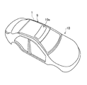
図1乃至図3は、本発明の実施形態1に係る車両用成形天井材1を備えた車両10を示す。該車両10は、ルーフパネル9の車両前側にサンルーフ10aを有し、上記車両用成形天井材1は、上記ルーフパネル9の車室内側の全域を覆うように配設されている。
Hereinafter, embodiments of the present invention will be described in detail with reference to the drawings. The following description of the preferred embodiment is merely exemplary in nature.
1 to 3 show a
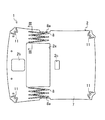
上記車両用成形天井材1は、図2に示すように、略矩形パネル状の天井材本体2を備え、該天井材本体2のルーフパネル9側には、図示しないハーネス線及び防音材等が粘着テープや接着剤で取り付けられている。
As shown in FIG. 2, the
上記天井材本体2の車幅方向両側部分は、車幅方向両端に近づくにつれて次第に下方に位置するよう傾斜しており、上記天井材本体2の上記サンルーフ10aに対応する位置には、平面視で略矩形状をなすとともに車幅方向に長く延びるサンルーフ用開口部2aが形成されている。
The both sides of the
また、上記天井材本体2における上記サンルーフ用開口部2aの車両前側中央部分には、平面視で矩形状をなす前側ランプユニット用開口部2bが形成されている。
Further, a front lamp unit opening 2b having a rectangular shape in plan view is formed in the vehicle front side central portion of the
さらに、上記天井材本体2における上記サンルーフ用開口部2aの車両後側中央部分には、平面視で矩形状をなす後側ランプユニット用開口部2cが形成されている。
Further, a rear lamp unit opening 2c having a rectangular shape in a plan view is formed in the vehicle rear side central portion of the
上記天井材本体2は、図3に示すように、硬質発泡ウレタンからなるウレタン層3と、該ウレタン層3の車室内側に積層されたガラス繊維からなる第1補強層4と、上記ウレタン層3の車室外側に積層されたガラス繊維からなる第2補強層5と、上記第1補強層4の車室内側に貼り付けられた不織布からなる表皮層6と、上記第2補強層5の車室外側に貼り付けられた不織布からなる裏面層7とを備えている。
As shown in FIG. 3, the
上記天井材本体2の車室外側表面(裏面層7の車室外側の面)におけるサンルーフ用開口部2a周りの車幅方向両側部分には、図2に示すように、ホットメルト接着剤による第1接着剤塗布層8が形成されている。
As shown in FIG. 2, as shown in FIG. 2, a hot-melt adhesive is used on both sides in the vehicle width direction around the
該第1接着剤塗布層8は、上記天井材本体2の車室外側表面に対して、ホットメルト接着剤をジグザグに複数回折り返しながら車幅方向に連続的に塗布することにより形成されている。
The first
すなわち、上記第1接着剤塗布層8は、車幅方向に沿ってジグザグに折り返された形状をなしている。
That is, the first
上記第1接着剤塗布層8の各折り返し部分8aは、平面視で鋭角をなすV字状をなしており、上記各折り返し部分8aの頂部は、上記サンルーフ用開口部2aの車両前側の縁部及び車両後側の縁部の各延長線上に位置している。
Each folded
上記天井材本体2の車室外側表面における四隅には、ホットメルト接着剤による第2接着剤塗布層11がそれぞれ形成されている。
Second
該第2接着剤塗布層11は、上記天井材本体2の車室外側表面に対して、ホットメルト接着剤を上記天井材本体2の各隅部に沿ってジグザグに複数回折り返しながら連続的に塗布することにより形成されている。
The second
尚、上記第1及び第2接着剤塗布層8,11は、ウレタン層3、第1補強層4、第2補強層5、表皮層6及び裏面層7が積層された成形前シートに対して接着剤塗布用ロボットを用いて連続的に塗布することによって形成されている。
The first and second
また、図3では、便宜上、天井材本体2の各層の厚みを誇張して記載している。
In FIG. 3, the thickness of each layer of the
ここで、上記天井材本体2のサンルーフ用開口部2a周りの車幅方向両側部分の剛性を高めるために、当該部分の車室外側表面の全域にホットメルト接着剤を塗布することも考えられるが、そのようにすると、発泡ウレタン材や不織布等からなる天井材本体とホットメルト接着剤による塗布層とでは、熱膨張係数が異なるために使用環境によっては天井材本体にシワが発生してしまうおそれがある。また、車両用成形天井材1全体の重量も重くなるという問題が生じる。
Here, in order to increase the rigidity of the both sides in the vehicle width direction around the
これに対し、本発明の実施形態1では、天井材本体2のサンルーフ用開口部2a周りの車幅方向両側部分にホットメルト接着剤による第1接着剤塗布層8を設けてはいるものの、第1接着剤塗布層8の無い部分が車幅方向に所定間隔に設けられるようになるので、天井材本体2の熱膨張係数と異なる熱膨張係数の部分が少なくなるとともに偏って配置されないので天井材本体2にシワが発生し難い。
On the other hand, in
また、天井材本体2のサンルーフ用開口部2a周りにおける車幅方向両側部分の剛性を高めるためにホットメルト接着剤を必要最小限の塗布量しか用いないので、特許文献1のように補強リブを用意するとともに接着剤で天井材本体2に取り付けるといった作業も必要無く、軽量で、且つ、低コストな車両用成形天井材1にできる。
In addition, since only a minimum amount of hot melt adhesive is used to increase the rigidity of both sides in the vehicle width direction around the
そして、天井材本体2の車室外側表面におけるサンルーフ用開口部2a周りの車幅方向両側部分に第1接着剤塗布層8がバランス良く配置されるので、当該部分のあらゆる方向に対する剛性を高めることができる。
And since the 1st
また、上記第1接着剤塗布層8の各折り返し部分8aが平面視で鋭角をなすV字状をなしているので、第1接着剤塗布層8の各折り返し部分8aの第1接着剤塗布層8の幅が他の部分より広くなる。したがって、例えば、天井材本体2のサンルーフ用開口部2a周りにおいて他の部分より剛性を高めたい箇所に第1接着剤塗布層8の各折り返し部分8aを対応させることによって、天井材本体2をバランス良く剛性の高いものにできる。
Further, each folded
さらに、第1接着剤塗布層8がホットメルト接着剤をジグザグに折り返しながら車幅方向に沿って塗布することにより形成されているので、第1接着剤塗布層8において車幅方向と鈍角に交わる部分が多くなり、天井材本体2におけるサンルーフ用開口部2a周りの車幅方向両側部分において特に車幅方向の割れに対して強い部品にできる。
Furthermore, since the first
それに加えて、天井材本体2にホットメルト接着剤を塗布する際に、車両前後方向に途切れることなく一筆書きで塗布するので、車両用成形天井材1の製造時間を短縮することができる。
《発明の実施形態2》
図4は、本発明の実施形態2を示す。この実施形態2では、第1接着剤塗布層8の形状が実施形態1と異なるだけで、その他は実施形態1と同じであるため、以下、実施形態1と異なる部分のみを詳細に説明する。
In addition, when the hot melt adhesive is applied to the
<<
FIG. 4 shows
実施形態2の第1接着剤塗布層8は、上記天井材本体2の車室外側表面に対して、ホットメルト接着剤をジグザグに複数回折り返しながら車両前後方向に連続的に塗布することにより形成されている。
The first
すなわち、実施形態2の第1接着剤塗布層8の各折り返し部分8aは、平面視で鋭角をなすV字状をなしており、実施形態2の各折り返し部分8aの頂部は、上記サンルーフ用開口部2aにおける車幅方向両側の縁部又は天井材本体2の外側の縁部に接近した位置となっている。
That is, each folded
以上より、本発明の実施形態2によると、第1接着剤塗布層8において車両前後方向と鈍角に交わる部分が多くなり、天井材本体2におけるサンルーフ用開口部2a周りの車幅方向両側部分において特に車両前後方向の割れに対して強い部品にできる。
As described above, according to the second embodiment of the present invention, there are many portions of the first
尚、本発明の実施形態1,2では、天井材本体2に対してホットメルト接着剤をジグザグに折り返しながら塗布しているが、これに限らず、例えば、波状に折り返しながら塗布してもよい。
In
また、本発明の実施形態1,2では、天井材本体2におけるサンルーフ用開口部2a周りの車幅方向両側部分にそれぞれ1列の第1接着剤塗布層8を設けているが、それぞれ複数列の第1接着剤塗布層8を設けるようにしてもよい。
In the first and second embodiments of the present invention, one row of the first
また、本発明の実施形態1,2では、第1接着剤塗布層8を車両前後方向又は車幅方向に連続的に塗布して形成しているが、第1接着剤塗布層8を複数回に分けて塗布して形成するようにしてもよい。
In the first and second embodiments of the present invention, the first
本発明は、車両の車室内に設けられる車両用成形天井材及びその製造方法に適している。 INDUSTRIAL APPLICABILITY The present invention is suitable for a molded ceiling material for a vehicle provided in a vehicle interior of the vehicle and a method for manufacturing the same.
1 車両用成形天井材
2 天井材本体
2a サンルーフ用開口部
8 第1接着剤塗布層
9 ルーフパネル
10 車両
10a サンルーフ
DESCRIPTION OF
Claims (3)
上記天井材本体の車室外側表面における開口部周りの車幅方向両側部分は、ホットメルト接着剤を波状又はジグザグに折り返しながら車両前後方向又は車幅方向に沿って塗布することにより形成された接着剤塗布層を有することを特徴とする車両用成形天井材。 A molded ceiling material for a vehicle having a panel-like ceiling material body which is disposed on the vehicle interior side of a roof panel of a vehicle having a sunroof and has an opening corresponding to the sunroof,
The both sides in the vehicle width direction around the opening portion on the outer surface of the vehicle interior of the ceiling material body are formed by applying the hot melt adhesive along the vehicle front-rear direction or the vehicle width direction while folding back in a wavy or zigzag manner. A molded ceiling material for a vehicle having an agent coating layer.
上記接着剤塗布層の各折り返し部分は、平面視で鋭角をなすV字状をなしていることを特徴とする車両用成形天井材。 The molded ceiling member for a vehicle according to claim 1,
Each of the folded portions of the adhesive application layer has a V-shape that forms an acute angle in a plan view.
上記接着剤塗布層は、車幅方向に沿ってジグザグに折り返された形状をなしていることを特徴とする車両用成形天井材。 The molded ceiling material for a vehicle according to claim 2,
The above-mentioned adhesive coating layer has a zigzag folded shape along the vehicle width direction.
Priority Applications (1)
| Application Number | Priority Date | Filing Date | Title |
|---|---|---|---|
| JP2016082359A JP2017190108A (en) | 2016-04-15 | 2016-04-15 | Molded ceiling material for vehicles |
Applications Claiming Priority (1)
| Application Number | Priority Date | Filing Date | Title |
|---|---|---|---|
| JP2016082359A JP2017190108A (en) | 2016-04-15 | 2016-04-15 | Molded ceiling material for vehicles |
Publications (1)
| Publication Number | Publication Date |
|---|---|
| JP2017190108A true JP2017190108A (en) | 2017-10-19 |
Family
ID=60086113
Family Applications (1)
| Application Number | Title | Priority Date | Filing Date |
|---|---|---|---|
| JP2016082359A Pending JP2017190108A (en) | 2016-04-15 | 2016-04-15 | Molded ceiling material for vehicles |
Country Status (1)
| Country | Link |
|---|---|
| JP (1) | JP2017190108A (en) |
Citations (4)
| Publication number | Priority date | Publication date | Assignee | Title |
|---|---|---|---|---|
| JP2014133181A (en) * | 2014-04-25 | 2014-07-24 | Livedo Corporation | Sheet member and method for manufacturing the same |
| JP2015134554A (en) * | 2014-01-17 | 2015-07-27 | 住友電装株式会社 | Wiring module and manufacturing method for wiring module |
| JP2015524682A (en) * | 2012-06-29 | 2015-08-27 | ザ プロクター アンド ギャンブルカンパニー | Wearable article having an outermost layer that is a multi-component nonwoven fabric that provides improved mechanical properties |
| JP2015221647A (en) * | 2014-05-23 | 2015-12-10 | 豊和繊維工業株式会社 | Vehicle ceiling structure |
-
2016
- 2016-04-15 JP JP2016082359A patent/JP2017190108A/en active Pending
Patent Citations (4)
| Publication number | Priority date | Publication date | Assignee | Title |
|---|---|---|---|---|
| JP2015524682A (en) * | 2012-06-29 | 2015-08-27 | ザ プロクター アンド ギャンブルカンパニー | Wearable article having an outermost layer that is a multi-component nonwoven fabric that provides improved mechanical properties |
| JP2015134554A (en) * | 2014-01-17 | 2015-07-27 | 住友電装株式会社 | Wiring module and manufacturing method for wiring module |
| JP2014133181A (en) * | 2014-04-25 | 2014-07-24 | Livedo Corporation | Sheet member and method for manufacturing the same |
| JP2015221647A (en) * | 2014-05-23 | 2015-12-10 | 豊和繊維工業株式会社 | Vehicle ceiling structure |
Similar Documents
| Publication | Publication Date | Title |
|---|---|---|
| US20160375747A1 (en) | Bonding structure of vehicle members and bonding structure of backdoor | |
| US8764891B1 (en) | Headliner edge treatment | |
| JP5444520B1 (en) | Vehicle interior board and manufacturing method thereof | |
| JP2014083904A (en) | Vehicle exterior panel | |
| US20130337219A1 (en) | Panel | |
| JP6436021B2 (en) | Resin panel structure for vehicles and luggage door | |
| JP5628881B2 (en) | Interior materials for vehicles | |
| KR101705628B1 (en) | Automobile trunk board and its manufacturing method | |
| JP5943350B2 (en) | Interior material for vehicle and method for producing interior material for vehicle | |
| KR102083902B1 (en) | Material for head ling of vehicle | |
| JP2017190108A (en) | Molded ceiling material for vehicles | |
| JP2011136664A (en) | Vehicular interior trim | |
| JP6828644B2 (en) | Arrangement structure of sound absorbing material in vehicle interior materials | |
| JP6728231B2 (en) | Interior materials for vehicles | |
| JP2020511351A (en) | Foldable interior lining panel for automobiles | |
| JP5762272B2 (en) | Vehicle ceiling material | |
| US11858323B2 (en) | Convertible top element and convertible top for a convertible vehicle and convertible vehicle | |
| JP5953189B2 (en) | Vehicle interior material and method for manufacturing the same | |
| JP6997205B2 (en) | Car foldable interior lining panel | |
| NL2018905B1 (en) | Roof Module for a Vehicle and Method for Manufacturing a Roof Module | |
| JP2008168708A (en) | Glass structure for vehicle | |
| JP4255856B2 (en) | Sound absorbing material and manufacturing method thereof | |
| JP5651135B2 (en) | Interior materials for vehicles | |
| JP2018187883A (en) | Laminated structure of reinforcement material and resin molding for interior | |
| JP7249799B2 (en) | Decorative film and moving body |
Legal Events
| Date | Code | Title | Description |
|---|---|---|---|
| A621 | Written request for application examination |
Free format text: JAPANESE INTERMEDIATE CODE: A621 Effective date: 20190404 |
|
| A977 | Report on retrieval |
Free format text: JAPANESE INTERMEDIATE CODE: A971007 Effective date: 20200116 |
|
| A131 | Notification of reasons for refusal |
Free format text: JAPANESE INTERMEDIATE CODE: A131 Effective date: 20200121 |
|
| A02 | Decision of refusal |
Free format text: JAPANESE INTERMEDIATE CODE: A02 Effective date: 20200804 |