JP2017188260A - Electron gun assembly - Google Patents
Electron gun assembly Download PDFInfo
- Publication number
- JP2017188260A JP2017188260A JP2016075206A JP2016075206A JP2017188260A JP 2017188260 A JP2017188260 A JP 2017188260A JP 2016075206 A JP2016075206 A JP 2016075206A JP 2016075206 A JP2016075206 A JP 2016075206A JP 2017188260 A JP2017188260 A JP 2017188260A
- Authority
- JP
- Japan
- Prior art keywords
- cathode
- heater
- connection terminal
- electron gun
- screw
- Prior art date
- Legal status (The legal status is an assumption and is not a legal conclusion. Google has not performed a legal analysis and makes no representation as to the accuracy of the status listed.)
- Pending
Links
Images


Abstract
Description
本発明の実施形態は、電子銃構体に関する。 Embodiments described herein relate generally to an electron gun assembly.
電子銃構体は、クライストロンや進行波管などの直線ビームを利用する電子管に用いられている。
電子銃構体には、電子を放出するカソードと、カソードから間隔を置いて配置されたアノードと、カソードとアノードとの間に設けられたグリッドと、グリッド側とは反対側に設けられ、カソードを加熱するヒータと、が設けられている。
The electron gun structure is used for an electron tube using a straight beam such as a klystron or a traveling wave tube.
The electron gun assembly includes an electron emitting cathode, an anode spaced apart from the cathode, a grid provided between the cathode and the anode, and a cathode provided on the opposite side of the grid. And a heater for heating.
ここで、カソードは、カソードスリーブと接合されている。カソードスリーブは、フランジ部と接合されている。フランジ部は、支持筒と接合されている。ヒータのリードは、ヒータ端子に接合されている。そして、これらの接合は、TIG溶接(Gas tungsten arc welding)にて行われる。 Here, the cathode is joined to the cathode sleeve. The cathode sleeve is joined to the flange portion. The flange portion is joined to the support cylinder. The heater lead is joined to the heater terminal. And these joining is performed by TIG welding (Gas tungsten arc welding).
各部を溶接により接合すれば、接合時に溶接部に溶融ムラが生じる場合がある。
特に、断面積が小さく、且つ、タングステンなど脆性材料からなるヒータのリードは、過溶融による脆化や痩せ、あるいは、溶融不足による接合強度の低下などが生じ易く、断線が生じるおそれが高くなる。
If each part is joined by welding, melt | fusion nonuniformity may arise in a welding part at the time of joining.
In particular, a heater lead made of a brittle material such as tungsten having a small cross-sectional area is liable to become brittle or thin due to overmelting, or to have a reduced bonding strength due to insufficient melting, thereby increasing the risk of disconnection.
また、近年、電子管の大電力化に伴い、電子を多く得るためにカソードを高温で使用する場合が多くなっている。そのため、カソードの寿命が短くなる傾向にある。この場合、寿命となったカソードを交換することが考えられるが、カソードやヒータのリードは、他の要素と溶接されているため交換ができない。また、ヒータのリードは断面積が小さく、且つ、脆性材料からなるので電子銃構体の組み立て時に折れたり、曲がったりするおそれがある。 In recent years, with the increase in power of the electron tube, the cathode is often used at a high temperature in order to obtain more electrons. Therefore, the life of the cathode tends to be shortened. In this case, it is conceivable to replace the cathode that has reached the end of its life, but the cathode and heater leads cannot be replaced because they are welded to other elements. Further, since the heater lead has a small cross-sectional area and is made of a brittle material, it may be bent or bent when the electron gun assembly is assembled.
本発明が解決しようとする課題は、カソードおよびヒータの組み立て性および交換性を向上させることができる電子銃構体を提供することである。 The problem to be solved by the present invention is to provide an electron gun assembly capable of improving the assembly and exchangeability of the cathode and the heater.
実施形態に係る電子銃構体は、支持筒と、前記支持筒と着脱自在に設けられ、少なくとも、カソードと、前記カソードの電子放射面側とは反対側に設けられたヒータと、を有するカソードユニットと、前記カソードユニットの前記カソード側に設けられたアノードと、前記カソードユニットと、前記アノードと、の間に設けられたグリッドと、を備えている。 An electron gun assembly according to an embodiment includes a support cylinder, a cathode unit that is detachable from the support cylinder, and includes at least a cathode and a heater provided on the opposite side of the cathode from the electron emission surface side. And an anode provided on the cathode side of the cathode unit, and a grid provided between the cathode unit and the anode.
以下、図面を参照しつつ、実施の形態について例示をする。なお、各図面中、同様の構成要素には同一の符号を付して詳細な説明は適宜省略する。
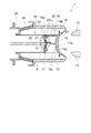
図1は、本実施の形態に係る電子銃構体1を例示するための模式断面図である。
図2は、図1中のA部の模式拡大図である。
電子銃構体1は、例えば、IOT(誘導出力増幅管)などの直線ビームを用いる電子管に用いることができる。
ただし、電子銃構体1の用途は、IOTに限定されるわけではない。
図1に示すように、電子銃構体1には、カソードユニット10、グリッド12、アノード13、ウェーネルト電極14、支持筒18、ヒータ端子20、絶縁筒24、およびカソード支持体25が設けられている。
Hereinafter, embodiments will be illustrated with reference to the drawings. In addition, in each drawing, the same code | symbol is attached | subjected to the same component and detailed description is abbreviate | omitted suitably.
FIG. 1 is a schematic cross-sectional view for illustrating an electron gun assembly 1 according to the present embodiment.
FIG. 2 is a schematic enlarged view of part A in FIG.
The electron gun assembly 1 can be used for an electron tube using a linear beam such as an IOT (inductive output amplifier tube).
However, the use of the electron gun assembly 1 is not limited to the IOT.
As shown in FIG. 1, the electron gun assembly 1 is provided with a
まず、カソードユニット10について説明する。
後述するように、カソードユニット10は、支持筒18に対して着脱自在に設けられている。
カソードユニット10は、カソード11、ヒータ15、カソードスリーブ16、フランジ部17、接続用端子19、および絶縁部21を有する。
カソード11は、電子(熱電子)を放出する。
カソード11は、板状を呈し、グリッド12側とは反対側に突出するように湾曲している。
カソード11の平面形状は、例えば、円形とすることができる。
この場合、カソード11の直径寸法は、例えば、40mm程度とすることができる。
カソード11のグリッド12側の面は、電子放射面11aとなっている。電子放射面11aは、所定の曲率を有する凹状の曲面となっている。
First, the
As will be described later, the
The
The cathode 11 emits electrons (thermoelectrons).
The cathode 11 has a plate shape and is curved so as to protrude to the side opposite to the
The planar shape of the cathode 11 can be circular, for example.
In this case, the diameter dimension of the cathode 11 can be about 40 mm, for example.
The surface of the cathode 11 on the
また、カソード11は、例えば、含浸型カソードとすることができる。
カソード11が含浸型カソードである場合には、カソード11は、例えば、ポーラスタングステンからなる基体に電子放射物質を含浸することで形成することができる。
この場合、ポーラスタングステンの気孔率は、例えば、20%程度とすることができる。
電子放射物質としては、例えば、酸化バリウム、酸化カルシウム、および酸化アルミニウムからなる金属酸化物を用いることができる。
The cathode 11 can be an impregnated cathode, for example.
When the cathode 11 is an impregnated cathode, the cathode 11 can be formed by, for example, impregnating a substrate made of porous tungsten with an electron emitting substance.
In this case, the porosity of porous tungsten can be about 20%, for example.
As the electron emitting substance, for example, a metal oxide composed of barium oxide, calcium oxide, and aluminum oxide can be used.
電子放射面11aには、イリジウム金属薄膜、あるいはオスミウム−ルテニウム合金薄膜が設けられている。イリジウム金属薄膜、あるいはオスミウム−ルテニウム合金薄膜は、例えば、スパッタリング法を用いて形成することができる。イリジウム金属薄膜、あるいはオスミウム−ルテニウム合金薄膜を設けるようにすれば、電子放射面11aの仕事関数を低減させることができる。
The
ヒータ15は、カソードスリーブ16、カソード11、およびフランジ部17により画された空間に設けられている。
ヒータ15は、カソード11の電子放射面11a側とは反対側に設けられている。
ヒータ15は、ジュール熱を発生させる。ヒータ15は、発生させた熱によりカソード11を加熱する。
ヒータ15は、例えば、タングステン線や、レニウム−タングステン合金線などから形成することができる。
ヒータ15は、例えば、直径寸法が1mm程度のタングステン線から形成することができる。
ヒータ15は、リード15a、リード15b、および発熱部15cを有する。
リード15aは、発熱部15cと一体に形成されている。リード15aの発熱部15c側とは反対側の端部は、接続用端子19と電気的に接続される。
リード15bは、発熱部15cと一体に形成されている。リード15bの発熱部15c側とは反対側の端部は、フランジ部17と電気的に接続される。
The
The
The
The
The
The
The
The
カソードスリーブ16は、円筒状を呈している。
カソードスリーブ16の一方の端部の内面には、カソード11の外周端面が接合されている。カソードスリーブ16の他方の端部の内面には、フランジ部17の外周端面が接合されている。
例えば、高融点金属を用いたロー付けにより、カソードスリーブ16とカソード11、および、カソードスリーブ16とフランジ部17を接合することができる。高融点金属は、例えば、モリブデン−ルテニウム−ニッケル合金などである。
カソードスリーブ16は、例えば、モリブデンや、レニウム−モリブデン合金などから形成することができる。
The
The outer peripheral end surface of the cathode 11 is joined to the inner surface of one end portion of the
For example, the cathode sleeve 16 and the cathode 11 and the
The
フランジ部17は、円板状を呈している。フランジ部17は、導電性を有する。フランジ部17は、カソードスリーブ16の、カソード11が接合される側とは反対側の端部に接合されている。フランジ部17は、例えば、モリブデンや、レニウム−モリブデン合金などから形成することができる。
The
図2に示すように、フランジ部17にはネジ孔17aが設けられている。ネジ孔17aは、フランジ部17を貫通している。ネジ孔17aは、複数設けられている。複数のネジ孔17aは、フランジ部17の円周方向に均等に配置することができる。ネジ孔17aは、カソードユニット10を支持筒18に固定するために設けられている。そのため、カソードユニット10は、支持筒18に対して着脱自在に設けることができる。
As shown in FIG. 2, the
また、フランジ部17には取付け孔17bが設けられている。取付け孔17bは、フランジ部17を貫通している。取付け孔17bには、リード15bの端部が挿入されている。フランジ部17には、ヒータ15のリード15bが接合される。例えば、高融点金属を用いたロー付けにより、取付け孔17bに挿入されたリード15bの端部と、フランジ部17とを接合することができる。高融点金属は、例えば、モリブデン−ルテニウム−ニッケル合金などである。
The
また、フランジ部17には取付け孔17cが設けられている。取付け孔17cは、フランジ部17を貫通している。取付け孔17cには、絶縁部21が挿入されている。例えば、高融点金属を用いたロー付けにより、取付け孔17cに挿入された絶縁部21と、フランジ部17とを接合することができる。高融点金属は、例えば、モリブデン−ルテニウム−ニッケル合金などである。なお、絶縁部21はセラミックスなどから形成される。そのため、ロー付けをし易くするために、絶縁部21の外側面には金属膜が形成されている。金属膜は、例えば、メタライズ法などにより形成することができる。
The
接続用端子19は、導電性を有する。接続用端子19には、ネジ孔19aが設けられている。ネジ孔19aは、接続用端子19を貫通している。ネジ孔19aには、ヒータ端子20の一方の端部に設けられたネジ部20aがねじ込まれている。すなわち、接続用端子19には、ヒータ端子20に設けられたネジ部20aに適合するネジ孔19aが設けられている。
また、接続用端子19には、取付け孔19bが設けられている。取付け孔19bは、接続用端子19を貫通している。取付け孔19bには、リード15aの端部が挿入されている。接続用端子19には、ヒータ15のリード15aが接合される。例えば、高融点金属を用いたロー付けにより、取付け孔19bに挿入されたリード15aの端部と、接続用端子19とを接合することができる。高融点金属は、例えば、モリブデン−ルテニウム−ニッケル合金などである。
接続用端子19は、モリブデン、タングステン、ステンレス、鉄、白金、タンタル、ニオブ、レ二ウム、コバールからなる群より選ばれた少なくとも1種を含む。
The
The
The
絶縁部21は、フランジ部17と接続用端子19との間に設けられている。
絶縁部21には、取付け孔21aが設けられている。取付け孔21aは、絶縁部21を貫通している。取付け孔21aには、接続用端子19が挿入されている。例えば、高融点金属を用いたロー付けにより、取付け孔21aに挿入された接続用端子19と、絶縁部21とを接合することができる。高融点金属は、例えば、モリブデン−ルテニウム合金などである。なお、絶縁部21はセラミックスなどから形成される。そのため、ロー付けをし易くするために、取付け孔21aの内面には金属膜が形成されている。金属膜は、例えば、メタライズ法などにより形成することができる。
絶縁部21は、耐熱性と、絶縁性を有する材料から形成されている。絶縁部21は、例えば、セラミックスなどから形成することができる。
The insulating
The insulating
The insulating
次に、図1に戻って、電子銃構体1に設けられた他の要素について説明する。
グリッド12は、カソードユニット10とアノード13との間に設けられている。グリッド12は、カソード11とアノード13の相互作用領域に設けられている。
グリッド12の平面形状は、例えば、円形とすることができる。
グリッド12と電子放射面11aとの間には、数十μmないし数百μmの隙間が設けられている。
グリッド12は、内周部と外周部を有する。グリッド12の内周部は、例えば、編み目状を呈し、電子を通過させる複数の開口部を有している。グリッド12の内周部は、電子放射面11aに沿うように湾曲している。グリッド12の外周部は、内周部を囲むように設けられ、ビームを通過させる開口部を有していない。
Next, returning to FIG. 1, other elements provided in the electron gun assembly 1 will be described.
The
The planar shape of the
A gap of several tens to several hundreds of μm is provided between the
The
グリッド12は、耐熱性と導電性を有する材料から形成されている。グリッド12は、例えば、パイロリティック・グラファイト(PG;Pyrolytic Graphite)などから形成することができる。なお、グリッド12は、モリブデン、レニウム−モリブデン合金、タンタル、ニオブ、タングステンなどの高融点金属およびこれらの合金から形成することもできる。
The
グリッド12は、ウェーネルト電極14と電気的に接続されている。
また、グリッド12は、カソードユニット10と接合することもできる。例えば、高融点金属を用いたロー付けにより、グリッド12の外周部とカソードスリーブ16の外側面とを接合することができる。高融点金属は、例えば、モリブデン−ルテニウム合金などである。
グリッド12とカソードユニット10を接合すれば、グリッド・カソード一体型構造体を構成することができる。
The
Further, the
If the
アノード13は、カソード11と対峙させて設けられている。アノード13は、カソードユニット10のカソード側に設けられている。アノード13は、カソード11の電子放射面11a側に設けられている。アノード13は、中央部分を貫通する孔部を有している。
例えば、電子銃構体1、図示しないドリフト管、および図示しないコレクタを有するIOTの場合には、アノード13は、図示しないドリフト管に設けることができる。
The
For example, in the case of an IOT having the electron gun assembly 1, a drift tube (not shown), and a collector (not shown), the
ウェーネルト電極14は、円筒状を呈している。
ウェーネルト電極14は、例えば、非磁性のステンレスやモリブデンなどから形成することができる。
ウェーネルト電極14の一方の端部の近傍には、カソード11とグリッド12が設けられている。
The
The
A cathode 11 and a
支持筒18は、円筒状を呈している。支持筒18の、カソードユニット10側の端部には取り付け座18aが設けられている。取り付け座18aの、ネジ孔17aに対応する位置には、ネジ22を挿入する孔が設けられている。取り付け座18aの中央には孔が設けられ、孔の内部に接続用端子19および絶縁部21が露出している。そのため、取り付け座18aの中央に設けられた孔を介して、接続用端子19に設けられたネジ孔19aにヒータ端子20のネジ部20aをねじ込むことができる。
The
カソードユニット10は、ネジ22により支持筒18に取り付けられている。そのため、カソードユニット10を支持筒18から取り外す際には、ネジ22を緩めるようにする。カソードユニット10を支持筒18に取り付ける際には、カソードユニット10を支持筒18に載せた状態でネジ22を締め付ける。
The
支持筒18の、カソードユニット10側とは反対側の端部の近傍は、カソード支持体25と溶接されている。
支持筒18は、例えば、モリブデンなどから形成することができる。
The vicinity of the end of the
The
ヒータ端子20は、柱状を呈している。
ヒータ端子20は、支持筒18の内部を軸方向に延びている。
ヒータ端子20の一方の端部には、ネジ部20aが設けられている。ネジ部20aは、接続用端子19のネジ孔19aにねじ込まれる。ヒータ端子20は、例えば、モリブデンやタングステンなどから形成することができる。
ネジ部20aをネジ孔19aにねじ込むことで、接続用端子19を介して、ヒータ端子20とヒータ15のリード15aとが電気的に接続される。
The
The
A
By screwing the
絶縁筒24は、外観が円錐台状の筒体とすることができる。
絶縁筒24の一端はウェーネルト電極14と接合されている。絶縁筒24の他端は、カソード支持体25と接合されている。
The insulating
One end of the insulating
例えば、貴金属を用いたロー付けにより、絶縁筒24とウェーネルト電極14、および、絶縁筒24とカソード支持体25を接合することができる。貴金属は、例えば、金ロー、銀ローなどである。
なお、絶縁筒24はセラミックスなどから形成される。そのため、ロー付けをし易くするために、絶縁筒24の両端には金属膜が形成されている。金属膜は、例えば、メタライズ法などにより形成することができる。
絶縁筒24は、耐熱性と、絶縁性を有する材料から形成されている。
絶縁筒24は、例えば、セラミックスなどから形成することができる。
For example, the insulating
The insulating
The insulating
The insulating
カソード支持体25は、円筒状を呈している。
カソード支持体25は、金属などの導電性材料から形成されている。
The
The
次に、電子銃構体1の作用について説明する。
カソード11には、カソード支持体25、支持筒18、フランジ部17およびカソードスリーブ16を介して、図示しない電源から所定の負の直流電圧が印加される。
アノード13には、図示しない電源から所定の正の直流電圧が印加される。
グリッド12には、ウェーネルト電極14を介して、図示しないバイアス電源から直流の負のバイアス電圧が印加される。
Next, the operation of the electron gun assembly 1 will be described.
A predetermined negative DC voltage is applied to the cathode 11 from a power source (not shown) via the
A predetermined positive DC voltage is applied to the
A negative DC bias voltage is applied to the
ヒータ15には、図示しない加熱電源から所定の電力が印加される。
図示しない加熱電源には、ヒータ端子20、接続用端子19、ヒータリード15aを介して発熱部15cの一端が電気的に接続されている。
また、図示しない加熱電源には、カソード支持体25、支持筒18、フランジ部17およびリード15bを介して発熱部15cの他端が電気的に接続されている。
A predetermined power is applied to the
One end of the
Further, the other end of the
発熱部15cに印加された電力により、発熱部15cにおいてジュール熱が生じる。
発生したジュール熱によりカソード11が加熱される。
真空中において、カソード11が加熱されると、カソード11から電子が放出される。 カソード11から放出された電子は、グリッド12によりグリッド12を通過する量が制御される。
グリッド12を通過した電子は、アノード13により加速される。
Joule heat is generated in the
The cathode 11 is heated by the generated Joule heat.
When the cathode 11 is heated in a vacuum, electrons are emitted from the cathode 11. The amount of electrons emitted from the cathode 11 is controlled by the
The electrons that have passed through the
以上に説明したように、カソードユニット10においては、カソード11、ヒータ15、カソードスリーブ16、フランジ部17、接続用端子19、および絶縁部21が一体的に設けられている。また、カソードユニット10は、支持筒18に対して着脱自在に設けられている。
そのため、カソード11またはヒータ15を交換する必要が生じた場合には、カソードユニット10を支持筒18から取り外し、新しいカソードユニット10を支持筒18に取り付ける様にすることができる。
また、ヒータ15のリード15aは接続用端子19と接合され、ヒータ15のリード15bはフランジ部17と接合されている。そのため、カソードユニット10の交換時に、リード15aおよびリード15bが折れたり、曲がったりすることがない。
As described above, in the
Therefore, when the cathode 11 or the
The lead 15 a of the
支持筒18の内部にヒータ15のリード15aを挿入し、リード15aとヒータ端子20を溶接などで接合するのは困難である。また、リード15aとヒータ端子20を溶接などで接合すれば、過溶融による脆化や痩せ、あるいは、溶融不足による接合強度の低下などが生じ易く、断線が生じるおそれが高くなる。
It is difficult to insert the
接続用端子19に設けられたネジ孔19aにヒータ端子20のネジ部20aがねじ込まれることで、ヒータ15とヒータ端子20とが電気的に接続される。そのため、カソードユニット10の取り付け(ヒータ15とヒータ端子20の電気的な接続)、およびカソードユニット10の取り外しが容易となる。なお、ヒータ端子20は、リード15aに比べて剛性が高いので、カソードユニット10の交換時に、ヒータ端子20が折れたり、曲がったりするおそれは低い。
When the
また、カソードユニット10は、ウェーネルト電極14や支持筒18などとは別に組み立てることができるので、カソードユニット10の組立作業が容易となる。
Moreover, since the
図3は、他の実施形態に係る接続用端子19および絶縁部21を例示するための模式断面図である。
図2に例示をしたものの場合には、高融点金属を用いたロー付けにより、取付け孔21aに挿入された接続用端子19と、絶縁部21とを接合している。
また、高融点金属を用いたロー付けにより、取付け孔17cに挿入された絶縁部21と、フランジ部17とを接合している。
FIG. 3 is a schematic cross-sectional view for illustrating a
In the case of the example illustrated in FIG. 2, the
Further, the insulating
これに対し、図3に例示をしたものの場合には、接続用端子19の外側面にネジ部19cを設けている。
そして、絶縁部21には、接続用端子19の外側面に設けられたネジ部19cに適合するネジ孔21bが設けられている。ネジ孔21bは、前述した取付け孔21aに代えて設けられている。
また、絶縁部21の外側面にネジ部21cを設けている。
そして、フランジ部17には、絶縁部21の外側面に設けられたネジ部21cに適合するネジ孔17dが設けられている。ネジ孔17dは、前述した取付け孔17cに代えて設けられている。
On the other hand, in the case illustrated in FIG. 3, a
The insulating
In addition, a
The
この様にすれば、接続用端子19および絶縁部21の取り付け、取り外しが容易となる。そのため、カソードユニット10の組立作業における作業効率を向上させることができる。
In this way, the
以上、本発明のいくつかの実施形態を例示したが、これらの実施形態は、例として提示したものであり、発明の範囲を限定することは意図していない。これら新規な実施形態は、その他の様々な形態で実施されることが可能であり、発明の要旨を逸脱しない範囲で、種々の省略、置き換え、変更などを行うことができる。これら実施形態やその変形例は、発明の範囲や要旨に含まれるとともに、特許請求の範囲に記載された発明とその均等の範囲に含まれる。また、前述の各実施形態は、相互に組み合わせて実施することができる。 As mentioned above, although several embodiment of this invention was illustrated, these embodiment is shown as an example and is not intending limiting the range of invention. These novel embodiments can be implemented in various other forms, and various omissions, replacements, changes, and the like can be made without departing from the spirit of the invention. These embodiments and modifications thereof are included in the scope and gist of the invention, and are included in the invention described in the claims and equivalents thereof. Further, the above-described embodiments can be implemented in combination with each other.
1 電子銃構体、10 カソードユニット、11 カソード、11a 電子放射面、12 グリッド、13 アノード、14 ウェーネルト電極、15 ヒータ、15a リード、15b リード、15c 発熱部、16 カソードスリーブ、17 フランジ部、17a ネジ孔、17b 取付け孔、17c 取付け孔、17d ネジ孔、18 支持筒、18a 取り付け座、19 接続用端子、19a ネジ孔、19b 取付け孔、19c ネジ部、20 ヒータ端子、20a ネジ部、21 絶縁部、21a 取付け孔、21b ネジ孔、21c ネジ部、22 ネジ、24 絶縁筒、25 カソード支持体 1 Electron Gun Structure, 10 Cathode Unit, 11 Cathode, 11a Electron Emission Surface, 12 Grid, 13 Anode, 14 Wehnelt Electrode, 15 Heater, 15a Lead, 15b Lead, 15c Heating Part, 16 Cathode Sleeve, 17 Flange Part, 17a Screw Hole, 17b Mounting hole, 17c Mounting hole, 17d Screw hole, 18 Support cylinder, 18a Mounting seat, 19 Connection terminal, 19a Screw hole, 19b Mounting hole, 19c Screw part, 20 Heater terminal, 20a Screw part, 21 Insulating part , 21a Mounting hole, 21b Screw hole, 21c Screw part, 22 Screw, 24 Insulating cylinder, 25 Cathode support
Claims (5)
前記支持筒と着脱自在に設けられ、少なくとも、カソードと、前記カソードの電子放射面側とは反対側に設けられたヒータと、を有するカソードユニットと、
前記カソードユニットの前記カソード側に設けられたアノードと、
前記カソードユニットと、前記アノードと、の間に設けられたグリッドと、
を備えた電子銃構体。 A support tube;
A cathode unit provided detachably with the support tube, and having at least a cathode and a heater provided on the side opposite to the electron emission surface side of the cathode;
An anode provided on the cathode side of the cathode unit;
A grid provided between the cathode unit and the anode;
An electron gun structure with
前記カソードユニットは、
導電性を有し、前記ヒータの一方のリードが接合されたフランジ部と、
導電性を有し、前記ヒータの他方のリードが接合され、前記ヒータ端子に設けられた前記ネジ部に適合するネジ孔が設けられた接続用端子と、
絶縁性を有し、前記フランジ部と前記接続用端子との間に設けられた絶縁部と、
をさらに有する請求項1記載の電子銃構体。 A heater terminal extending through the inside of the support tube and having a threaded portion at one end;
The cathode unit is
A flange portion having conductivity, to which one lead of the heater is joined;
A connection terminal having conductivity, the other lead of the heater being joined, and a screw hole adapted to the screw portion provided in the heater terminal;
Having an insulating property, an insulating portion provided between the flange portion and the connection terminal;
The electron gun assembly according to claim 1, further comprising:
前記絶縁部には、前記接続用端子の外側面に設けられた前記ネジ部に適合するネジ孔が設けられている請求項1または2に記載の電子銃構体。 A screw portion is provided on the outer surface of the connection terminal,
3. The electron gun assembly according to claim 1, wherein the insulating portion is provided with a screw hole adapted to the screw portion provided on an outer surface of the connection terminal.
前記フランジ部には、前記絶縁部の外側面に設けられた前記ネジ部に適合するネジ孔が設けられている請求項1〜3のいずれか1つに記載の電子銃構体。 A screw part is provided on the outer surface of the insulating part,
The electron gun assembly according to any one of claims 1 to 3, wherein the flange portion is provided with a screw hole adapted to the screw portion provided on an outer surface of the insulating portion.
Priority Applications (1)
| Application Number | Priority Date | Filing Date | Title |
|---|---|---|---|
| JP2016075206A JP2017188260A (en) | 2016-04-04 | 2016-04-04 | Electron gun assembly |
Applications Claiming Priority (1)
| Application Number | Priority Date | Filing Date | Title |
|---|---|---|---|
| JP2016075206A JP2017188260A (en) | 2016-04-04 | 2016-04-04 | Electron gun assembly |
Publications (1)
| Publication Number | Publication Date |
|---|---|
| JP2017188260A true JP2017188260A (en) | 2017-10-12 |
Family
ID=60044933
Family Applications (1)
| Application Number | Title | Priority Date | Filing Date |
|---|---|---|---|
| JP2016075206A Pending JP2017188260A (en) | 2016-04-04 | 2016-04-04 | Electron gun assembly |
Country Status (1)
| Country | Link |
|---|---|
| JP (1) | JP2017188260A (en) |
-
2016
- 2016-04-04 JP JP2016075206A patent/JP2017188260A/en active Pending
Similar Documents
| Publication | Publication Date | Title |
|---|---|---|
| US10734188B2 (en) | X-ray tube for improving electron focusing | |
| US9029795B2 (en) | Radiation generating tube, and radiation generating device and apparatus including the tube | |
| US8300769B2 (en) | Microminiature X-ray tube with triode structure using a nano emitter | |
| JP5845342B2 (en) | X-ray tube and electron-emitting device for X-ray tube | |
| KR20160102743A (en) | Field Emission X-Ray Source Device | |
| JP6311165B2 (en) | Double tube support for electron emitters | |
| JP4230565B2 (en) | X-ray tube | |
| JP7092664B2 (en) | X-ray tube cathode | |
| JP6792676B1 (en) | X-ray tube | |
| JP2017188260A (en) | Electron gun assembly | |
| WO2008062666A1 (en) | Electron beam irradiation device | |
| JP4781156B2 (en) | Transmission X-ray tube | |
| US20220208506A1 (en) | Electron beam emitting assembly | |
| JP5886550B2 (en) | Electron beam irradiation apparatus and electron beam transmission unit | |
| KR20170003083A (en) | Manufacturing Process For Field Emission X-ray Source Device | |
| KR20160102748A (en) | Field Emission X-Ray Source Device | |
| KR100487937B1 (en) | Magnetron | |
| JP6064456B2 (en) | X-ray tube | |
| RU2680150C1 (en) | Cathode unit of welding electron gun | |
| JP2015225818A (en) | Electron gun structure | |
| JP2016122593A (en) | Hollow cathode | |
| JP2015045038A (en) | Pressure gradient type plasma gun | |
| JP2015170407A (en) | Impregnated negative electrode structure | |
| RU156022U1 (en) | PULSE X-RAY TUBE | |
| JP6372571B2 (en) | X-ray tube |