JP2017186565A - Method and device for the gasification of feedstock - Google Patents
Method and device for the gasification of feedstock Download PDFInfo
- Publication number
- JP2017186565A JP2017186565A JP2017096559A JP2017096559A JP2017186565A JP 2017186565 A JP2017186565 A JP 2017186565A JP 2017096559 A JP2017096559 A JP 2017096559A JP 2017096559 A JP2017096559 A JP 2017096559A JP 2017186565 A JP2017186565 A JP 2017186565A
- Authority
- JP
- Japan
- Prior art keywords
- gasifier
- zone
- grate
- biochar
- feedstock
- Prior art date
- Legal status (The legal status is an assumption and is not a legal conclusion. Google has not performed a legal analysis and makes no representation as to the accuracy of the status listed.)
- Granted
Links
- 238000002309 gasification Methods 0.000 title claims abstract description 58
- 238000000034 method Methods 0.000 title claims description 64
- 238000007254 oxidation reaction Methods 0.000 claims abstract description 154
- 230000003647 oxidation Effects 0.000 claims abstract description 152
- 230000009467 reduction Effects 0.000 claims abstract description 87
- 238000006243 chemical reaction Methods 0.000 claims abstract description 19
- 239000007800 oxidant agent Substances 0.000 claims description 62
- 230000001590 oxidative effect Effects 0.000 claims description 61
- 238000000197 pyrolysis Methods 0.000 claims description 59
- 238000001035 drying Methods 0.000 claims description 34
- 239000000463 material Substances 0.000 claims description 20
- 230000006870 function Effects 0.000 claims description 11
- 238000010926 purge Methods 0.000 claims description 11
- 230000015572 biosynthetic process Effects 0.000 claims description 7
- 239000000919 ceramic Substances 0.000 claims description 7
- VYPSYNLAJGMNEJ-UHFFFAOYSA-N Silicium dioxide Chemical compound O=[Si]=O VYPSYNLAJGMNEJ-UHFFFAOYSA-N 0.000 claims description 6
- 230000007246 mechanism Effects 0.000 claims description 6
- TWNQGVIAIRXVLR-UHFFFAOYSA-N oxo(oxoalumanyloxy)alumane Chemical compound O=[Al]O[Al]=O TWNQGVIAIRXVLR-UHFFFAOYSA-N 0.000 claims description 6
- HBMJWWWQQXIZIP-UHFFFAOYSA-N silicon carbide Chemical compound [Si+]#[C-] HBMJWWWQQXIZIP-UHFFFAOYSA-N 0.000 claims description 6
- 229910010271 silicon carbide Inorganic materials 0.000 claims description 6
- 229910052814 silicon oxide Inorganic materials 0.000 claims description 6
- 238000002156 mixing Methods 0.000 claims description 5
- 238000011049 filling Methods 0.000 claims description 4
- 229910045601 alloy Inorganic materials 0.000 claims description 3
- 239000000956 alloy Substances 0.000 claims description 3
- 238000012544 monitoring process Methods 0.000 claims description 2
- 238000005070 sampling Methods 0.000 claims description 2
- 238000012360 testing method Methods 0.000 claims description 2
- 230000009257 reactivity Effects 0.000 claims 2
- 239000003795 chemical substances by application Substances 0.000 claims 1
- 210000003734 kidney Anatomy 0.000 claims 1
- 230000001960 triggered effect Effects 0.000 claims 1
- OKTJSMMVPCPJKN-UHFFFAOYSA-N Carbon Chemical compound [C] OKTJSMMVPCPJKN-UHFFFAOYSA-N 0.000 abstract description 16
- 229910052799 carbon Inorganic materials 0.000 abstract description 16
- 239000002028 Biomass Substances 0.000 abstract description 14
- 239000007787 solid Substances 0.000 abstract description 14
- 239000006227 byproduct Substances 0.000 abstract description 5
- 239000010791 domestic waste Substances 0.000 abstract description 2
- 239000002803 fossil fuel Substances 0.000 abstract description 2
- 239000002440 industrial waste Substances 0.000 abstract description 2
- 230000001629 suppression Effects 0.000 abstract 1
- 239000007789 gas Substances 0.000 description 112
- 238000006722 reduction reaction Methods 0.000 description 68
- 230000008569 process Effects 0.000 description 26
- CURLTUGMZLYLDI-UHFFFAOYSA-N Carbon dioxide Chemical compound O=C=O CURLTUGMZLYLDI-UHFFFAOYSA-N 0.000 description 14
- XLYOFNOQVPJJNP-UHFFFAOYSA-N water Chemical compound O XLYOFNOQVPJJNP-UHFFFAOYSA-N 0.000 description 13
- QVGXLLKOCUKJST-UHFFFAOYSA-N atomic oxygen Chemical compound [O] QVGXLLKOCUKJST-UHFFFAOYSA-N 0.000 description 11
- 239000001301 oxygen Substances 0.000 description 11
- 229910052760 oxygen Inorganic materials 0.000 description 11
- 239000000203 mixture Substances 0.000 description 9
- 229910002092 carbon dioxide Inorganic materials 0.000 description 8
- 230000008859 change Effects 0.000 description 8
- 238000013461 design Methods 0.000 description 8
- 230000005484 gravity Effects 0.000 description 8
- VNWKTOKETHGBQD-UHFFFAOYSA-N methane Chemical compound C VNWKTOKETHGBQD-UHFFFAOYSA-N 0.000 description 8
- 239000000126 substance Substances 0.000 description 8
- UGFAIRIUMAVXCW-UHFFFAOYSA-N Carbon monoxide Chemical compound [O+]#[C-] UGFAIRIUMAVXCW-UHFFFAOYSA-N 0.000 description 7
- 239000001569 carbon dioxide Substances 0.000 description 7
- 229910002091 carbon monoxide Inorganic materials 0.000 description 7
- 238000011144 upstream manufacturing Methods 0.000 description 7
- 239000003610 charcoal Substances 0.000 description 6
- 230000009471 action Effects 0.000 description 4
- 230000008901 benefit Effects 0.000 description 4
- 229920002678 cellulose Polymers 0.000 description 4
- 239000001913 cellulose Substances 0.000 description 4
- IJGRMHOSHXDMSA-UHFFFAOYSA-N Atomic nitrogen Chemical compound N#N IJGRMHOSHXDMSA-UHFFFAOYSA-N 0.000 description 3
- OKKJLVBELUTLKV-UHFFFAOYSA-N Methanol Chemical compound OC OKKJLVBELUTLKV-UHFFFAOYSA-N 0.000 description 3
- 230000015556 catabolic process Effects 0.000 description 3
- 239000000567 combustion gas Substances 0.000 description 3
- 238000002485 combustion reaction Methods 0.000 description 3
- 230000007423 decrease Effects 0.000 description 3
- 238000004200 deflagration Methods 0.000 description 3
- 238000006731 degradation reaction Methods 0.000 description 3
- 238000001704 evaporation Methods 0.000 description 3
- 230000008020 evaporation Effects 0.000 description 3
- 239000000446 fuel Substances 0.000 description 3
- 239000001257 hydrogen Substances 0.000 description 3
- 229910052739 hydrogen Inorganic materials 0.000 description 3
- 125000004435 hydrogen atom Chemical class [H]* 0.000 description 3
- 238000004519 manufacturing process Methods 0.000 description 3
- 238000012986 modification Methods 0.000 description 3
- 230000004048 modification Effects 0.000 description 3
- 238000005381 potential energy Methods 0.000 description 3
- 229910000753 refractory alloy Inorganic materials 0.000 description 3
- 238000003786 synthesis reaction Methods 0.000 description 3
- 229910000831 Steel Inorganic materials 0.000 description 2
- 230000006978 adaptation Effects 0.000 description 2
- 238000013459 approach Methods 0.000 description 2
- 239000003245 coal Substances 0.000 description 2
- 239000000470 constituent Substances 0.000 description 2
- 238000000354 decomposition reaction Methods 0.000 description 2
- 230000000694 effects Effects 0.000 description 2
- 230000020169 heat generation Effects 0.000 description 2
- XLYOFNOQVPJJNP-ZSJDYOACSA-N heavy water Substances [2H]O[2H] XLYOFNOQVPJJNP-ZSJDYOACSA-N 0.000 description 2
- 230000006698 induction Effects 0.000 description 2
- 229920005610 lignin Polymers 0.000 description 2
- 239000007788 liquid Substances 0.000 description 2
- 238000012423 maintenance Methods 0.000 description 2
- 150000001247 metal acetylides Chemical class 0.000 description 2
- 239000002245 particle Substances 0.000 description 2
- 230000000630 rising effect Effects 0.000 description 2
- 239000010935 stainless steel Substances 0.000 description 2
- 229910001220 stainless steel Inorganic materials 0.000 description 2
- 239000010959 steel Substances 0.000 description 2
- 229910000975 Carbon steel Inorganic materials 0.000 description 1
- LFQSCWFLJHTTHZ-UHFFFAOYSA-N Ethanol Chemical compound CCO LFQSCWFLJHTTHZ-UHFFFAOYSA-N 0.000 description 1
- 239000011449 brick Substances 0.000 description 1
- 239000010962 carbon steel Substances 0.000 description 1
- 238000001833 catalytic reforming Methods 0.000 description 1
- 238000004140 cleaning Methods 0.000 description 1
- 239000011365 complex material Substances 0.000 description 1
- 238000010411 cooking Methods 0.000 description 1
- 238000001816 cooling Methods 0.000 description 1
- 230000000593 degrading effect Effects 0.000 description 1
- 238000002716 delivery method Methods 0.000 description 1
- 230000000368 destabilizing effect Effects 0.000 description 1
- 238000007599 discharging Methods 0.000 description 1
- 229940079593 drug Drugs 0.000 description 1
- 239000003814 drug Substances 0.000 description 1
- 238000010981 drying operation Methods 0.000 description 1
- 238000005429 filling process Methods 0.000 description 1
- 239000012530 fluid Substances 0.000 description 1
- 239000012634 fragment Substances 0.000 description 1
- 239000002737 fuel gas Substances 0.000 description 1
- 239000003317 industrial substance Substances 0.000 description 1
- 230000003993 interaction Effects 0.000 description 1
- 238000011068 loading method Methods 0.000 description 1
- 238000007726 management method Methods 0.000 description 1
- WSFSSNUMVMOOMR-NJFSPNSNSA-N methanone Chemical compound O=[14CH2] WSFSSNUMVMOOMR-NJFSPNSNSA-N 0.000 description 1
- 239000003345 natural gas Substances 0.000 description 1
- 229910052757 nitrogen Inorganic materials 0.000 description 1
- 239000003921 oil Substances 0.000 description 1
- 238000005457 optimization Methods 0.000 description 1
- 239000005416 organic matter Substances 0.000 description 1
- 239000011148 porous material Substances 0.000 description 1
- 239000002243 precursor Substances 0.000 description 1
- 238000002203 pretreatment Methods 0.000 description 1
- 238000012545 processing Methods 0.000 description 1
- 230000001737 promoting effect Effects 0.000 description 1
- 239000002994 raw material Substances 0.000 description 1
- 230000004044 response Effects 0.000 description 1
- 238000004088 simulation Methods 0.000 description 1
- 239000011343 solid material Substances 0.000 description 1
- 238000010561 standard procedure Methods 0.000 description 1
- 239000000725 suspension Substances 0.000 description 1
- 230000002459 sustained effect Effects 0.000 description 1
- 238000007725 thermal activation Methods 0.000 description 1
- 238000005979 thermal decomposition reaction Methods 0.000 description 1
- 238000012546 transfer Methods 0.000 description 1
- 230000001052 transient effect Effects 0.000 description 1
- 239000002023 wood Substances 0.000 description 1
Images


Classifications
-
- F—MECHANICAL ENGINEERING; LIGHTING; HEATING; WEAPONS; BLASTING
- F23—COMBUSTION APPARATUS; COMBUSTION PROCESSES
- F23G—CREMATION FURNACES; CONSUMING WASTE PRODUCTS BY COMBUSTION
- F23G5/00—Incineration of waste; Incinerator constructions; Details, accessories or control therefor
- F23G5/24—Incineration of waste; Incinerator constructions; Details, accessories or control therefor having a vertical, substantially cylindrical, combustion chamber
- F23G5/26—Incineration of waste; Incinerator constructions; Details, accessories or control therefor having a vertical, substantially cylindrical, combustion chamber having rotating bottom
-
- C—CHEMISTRY; METALLURGY
- C10—PETROLEUM, GAS OR COKE INDUSTRIES; TECHNICAL GASES CONTAINING CARBON MONOXIDE; FUELS; LUBRICANTS; PEAT
- C10J—PRODUCTION OF PRODUCER GAS, WATER-GAS, SYNTHESIS GAS FROM SOLID CARBONACEOUS MATERIAL, OR MIXTURES CONTAINING THESE GASES; CARBURETTING AIR OR OTHER GASES
- C10J3/00—Production of combustible gases containing carbon monoxide from solid carbonaceous fuels
- C10J3/02—Fixed-bed gasification of lump fuel
- C10J3/20—Apparatus; Plants
- C10J3/22—Arrangements or dispositions of valves or flues
- C10J3/24—Arrangements or dispositions of valves or flues to permit flow of gases or vapours other than upwardly through the fuel bed
- C10J3/26—Arrangements or dispositions of valves or flues to permit flow of gases or vapours other than upwardly through the fuel bed downwardly
-
- C—CHEMISTRY; METALLURGY
- C10—PETROLEUM, GAS OR COKE INDUSTRIES; TECHNICAL GASES CONTAINING CARBON MONOXIDE; FUELS; LUBRICANTS; PEAT
- C10J—PRODUCTION OF PRODUCER GAS, WATER-GAS, SYNTHESIS GAS FROM SOLID CARBONACEOUS MATERIAL, OR MIXTURES CONTAINING THESE GASES; CARBURETTING AIR OR OTHER GASES
- C10J3/00—Production of combustible gases containing carbon monoxide from solid carbonaceous fuels
- C10J3/02—Fixed-bed gasification of lump fuel
- C10J3/20—Apparatus; Plants
- C10J3/34—Grates; Mechanical ash-removing devices
- C10J3/40—Movable grates
- C10J3/42—Rotary grates
-
- F—MECHANICAL ENGINEERING; LIGHTING; HEATING; WEAPONS; BLASTING
- F23—COMBUSTION APPARATUS; COMBUSTION PROCESSES
- F23G—CREMATION FURNACES; CONSUMING WASTE PRODUCTS BY COMBUSTION
- F23G5/00—Incineration of waste; Incinerator constructions; Details, accessories or control therefor
- F23G5/002—Incineration of waste; Incinerator constructions; Details, accessories or control therefor characterised by their grates
-
- F—MECHANICAL ENGINEERING; LIGHTING; HEATING; WEAPONS; BLASTING
- F23—COMBUSTION APPARATUS; COMBUSTION PROCESSES
- F23G—CREMATION FURNACES; CONSUMING WASTE PRODUCTS BY COMBUSTION
- F23G5/00—Incineration of waste; Incinerator constructions; Details, accessories or control therefor
- F23G5/02—Incineration of waste; Incinerator constructions; Details, accessories or control therefor with pretreatment
- F23G5/027—Incineration of waste; Incinerator constructions; Details, accessories or control therefor with pretreatment pyrolising or gasifying stage
-
- F—MECHANICAL ENGINEERING; LIGHTING; HEATING; WEAPONS; BLASTING
- F23—COMBUSTION APPARATUS; COMBUSTION PROCESSES
- F23G—CREMATION FURNACES; CONSUMING WASTE PRODUCTS BY COMBUSTION
- F23G5/00—Incineration of waste; Incinerator constructions; Details, accessories or control therefor
- F23G5/24—Incineration of waste; Incinerator constructions; Details, accessories or control therefor having a vertical, substantially cylindrical, combustion chamber
- F23G5/245—Incineration of waste; Incinerator constructions; Details, accessories or control therefor having a vertical, substantially cylindrical, combustion chamber with perforated bottom or grate
-
- C—CHEMISTRY; METALLURGY
- C10—PETROLEUM, GAS OR COKE INDUSTRIES; TECHNICAL GASES CONTAINING CARBON MONOXIDE; FUELS; LUBRICANTS; PEAT
- C10J—PRODUCTION OF PRODUCER GAS, WATER-GAS, SYNTHESIS GAS FROM SOLID CARBONACEOUS MATERIAL, OR MIXTURES CONTAINING THESE GASES; CARBURETTING AIR OR OTHER GASES
- C10J2300/00—Details of gasification processes
- C10J2300/09—Details of the feed, e.g. feeding of spent catalyst, inert gas or halogens
- C10J2300/0913—Carbonaceous raw material
- C10J2300/0916—Biomass
-
- F—MECHANICAL ENGINEERING; LIGHTING; HEATING; WEAPONS; BLASTING
- F23—COMBUSTION APPARATUS; COMBUSTION PROCESSES
- F23G—CREMATION FURNACES; CONSUMING WASTE PRODUCTS BY COMBUSTION
- F23G2900/00—Special features of, or arrangements for incinerators
- F23G2900/50002—Burning with downwards directed draft through the waste mass
Landscapes
- Engineering & Computer Science (AREA)
- Mechanical Engineering (AREA)
- Chemical & Material Sciences (AREA)
- General Engineering & Computer Science (AREA)
- Combustion & Propulsion (AREA)
- Oil, Petroleum & Natural Gas (AREA)
- Organic Chemistry (AREA)
- Processing Of Solid Wastes (AREA)
- Gasification And Melting Of Waste (AREA)
- Treatment Of Sludge (AREA)
Abstract
Description
[0001]本発明は、熱化学技術および設備に関し、詳細には、固体バイオマス、家庭および産業廃棄物、化石燃料ならびに他の炭素を含有する供給原料を下方流ガス化を利用してガス化するための工程および装置に関する。 [0001] The present invention relates to thermochemical techniques and equipment, and in particular, gasifies solid biomass, household and industrial waste, fossil fuels and other carbon-containing feedstocks using downflow gasification. The present invention relates to a process and an apparatus.
[0002]ガス化は、固体の有機物または炭素からなる物質(供給原料)が燃焼可能なガス混合体へ分解する継続的な熱分解工程である。形成された燃焼ガスの成分は主に一酸化炭素(CO)、水素(H2)およびメタン(CH4)である。他の非燃焼ガス、窒素(N2)、水蒸気(H2O)および二酸化炭素(CO2)もまた様々な量で存在する。ガス化の工程は、熱分解を伴いその後に部分的な酸化が続き、この部分的な酸化は空気または他の酸素含有ガスを一部が熱分解された供給原料に噴射することによって管理される。より具体的には、バイオマスのガス化は、水の蒸発、リグニン分解、セルロース誘導体の爆燃および炭素還元を含めた一連の反応である。外部の熱源がこの反応を開始するが、部分酸化が、供給原料の熱分解を維持するための熱を供給する。濃縮酸素が使用される場合、結果として生じるガス混合体は、合成ガスと呼ばれる。空気(窒素を含む)が酸化剤として使用される場合、結果として生じるガス混合気は、発生炉ガスと呼ばれる。簡素化するために、本明細書で使用される用語「発生炉ガス」は、合成ガスと発生炉ガスの両方を含めることにする。ガス混合体は共に、「燃料ガス」とみなされ、多くの工程において天然ガスの代わりに使用することができる。それらはまた、様々な工業用化学薬品およびモータ燃料を生成するための前駆物質として使用することもできる。バイオマスが供給原料として使用される場合、発生炉ガスのガス化および燃焼は、再生可能エネルギーの供給源であるとみなされる。 [0002] Gasification is a continuous pyrolysis process in which a substance consisting of solid organic matter or carbon (feedstock) is broken down into a combustible gas mixture. The components of the combustion gas formed are mainly carbon monoxide (CO), hydrogen (H2) and methane (CH4). Other non-combustion gases, nitrogen (N2), water vapor (H2O) and carbon dioxide (CO2) are also present in varying amounts. The gasification process is accompanied by pyrolysis followed by partial oxidation, which is controlled by injecting air or other oxygen-containing gas into the partially pyrolyzed feedstock. . More specifically, biomass gasification is a series of reactions including water evaporation, lignin degradation, deflagration of cellulose derivatives and carbon reduction. An external heat source initiates this reaction, but partial oxidation provides heat to maintain thermal decomposition of the feedstock. When concentrated oxygen is used, the resulting gas mixture is called synthesis gas. When air (including nitrogen) is used as the oxidant, the resulting gas mixture is referred to as generator gas. For simplicity, the term “generator gas” as used herein will include both synthesis gas and generator gas. Both gas mixtures are considered “fuel gases” and can be used in place of natural gas in many processes. They can also be used as precursors to produce various industrial chemicals and motor fuels. When biomass is used as a feedstock, gasification and combustion of the generator gas is considered to be a source of renewable energy.
[0003]一般的な事柄として、ガス化は、燃焼と比べて、固体供給原料から潜在的なエネルギーを取り出すためのより効率的で、コスト効果が高く、かつ環境に優しい代替形態を提供する。ガス化の結果として、供給原料の潜在的なエネルギーを発生炉ガスに変換することができ、この発生炉ガスはよりきれいな燃焼性があり、圧縮可能でより可搬性がある。発生炉ガスは、一部のエンジンおよびバーナーでは直に燃やされ、メタノールと水素を生成するために浄化される、あるいはフィッシャー・トロプシュ法ならびに他の方法および工程によって合成液体燃料に変換される場合もある。 [0003] As a general matter, gasification provides a more efficient, cost-effective and environmentally friendly alternative for extracting potential energy from solid feedstocks compared to combustion. As a result of gasification, the potential energy of the feedstock can be converted into generator gas, which is cleaner and more combustible, compressible and more portable. Reactor gas may be burned directly on some engines and burners, purified to produce methanol and hydrogen, or converted to synthetic liquid fuel by the Fischer-Tropsch process and other methods and processes. is there.
[0004]3つの一般的なガス化工程があり、流動化ベッドガス化、上方流ガス化および下方流ガス化である。本発明は、改良された下方流ガス化装置である。したがって流動化ベッドガス化および上方流ガス化の簡単な記載のみが提供されており、その後に現在の下方流ガス化がより十分に考察される。 [0004] There are three general gasification processes: fluidized bed gasification, upward flow gasification, and downward flow gasification. The present invention is an improved downflow gasifier. Thus, only a brief description of fluidized bed gasification and upflow gasification is provided, after which the current downflow gasification is more fully considered.
[0005]上方流ガス化
[0006]流の固定式ベッド(上方流)ガス化装置は、水蒸気、酸素および/または空気が上向きに通り抜けるように流れる大きな火格子の頂部にある供給原料の固定式のベッドで構成される。上方流ガス化装置は典型的には、頑丈で固まったり塊になったりしにくいために、それが透過性のベッドを形成する供給原料を必要とする。上方流ガス化装置は、酸化剤(水蒸気、酸素および/または空気)が底部からそこを通り抜けて入り、ガスとして頂部を通って出て行く供給原料のベッドで構成される。上方流ガス化装置は熱効率が高いが、これは上昇するガスが、進入するバイオマスを熱分解し乾燥させ、熱を移動させることで、出て行く発生炉ガスが、それがガス化装置を出て行くときに冷却されることが理由である。しかしながら発生炉ガス中には有意な量のタールが存在し、そのためこのようなタールは、生成時に燃やされなければ、使用する前に大々的に除去する必要がある。タールは、ガス化装置に対して再利用させることもできるが、タールの除去は複雑であり、コストがかかる。上方流ガス化装置は、150年の間石炭のガス化の定番であり、それはまた、バイオマス調理用レンジにおいても一般的である。
[0005] Upstream gasification
[0006] A fixed bed of flow (upstream) gasifier consists of a fixed bed of feedstock at the top of a large grate where water vapor, oxygen and / or air flow upwards. Upstream gasifiers typically require a feedstock that forms a permeable bed because they are sturdy and not prone to clumping or clumping. Upstream gasifiers consist of a bed of feedstock through which oxidants (water vapor, oxygen and / or air) enter through the bottom and exit as a gas through the top. Upstream gasifiers have high thermal efficiency, because the rising gas pyrolyzes and drys the incoming biomass and moves the heat away, so that the generated reactor gas exits the gasifier. The reason is that it is cooled when going. However, there is a significant amount of tar in the generator gas, so such tar must be removed extensively before use if it is not burned during production. Tar can be recycled to the gasifier, but tar removal is complex and costly. Upstream gasifiers have been a staple of coal gasification for 150 years and are also common in biomass cooking ranges.
[0007]流動化ベッドガス化
[0008]流動化ベッドガス化において、酸化剤は、固体粒子のベッドを通り抜けるように固体粒子を懸濁状態に保持するのに十分な速度で吹き込まれる。供給原料がガス化装置に投入され、極めて迅速にベッド材料と混合され、外部からあるいは熱伝達媒体を使用してほとんど瞬間的にベッド温度まで加熱される。このような流動化ベッドガス化装置の大半は、炭化物(発生炉ガス流内に運ばれる)を最小限にし、発生炉ガスから流動化媒体を除去するために内部サイクロンを装備する。主な利点には、供給原料の適応性および反応温度を容易に管理する能力が含まれ、これにより事前処理の必要がなく、微細に粒状にされた材料(おがくずなど)のガス化が可能になる。流動化ベッドガス化装置はまた、大きなサイズに極めて良好に拡大される。残念なことに、供給の問題、ベッドの不安定性、残留炭素および灰の蓄積がガスチャネル内に焼結するなどが生じる。他の欠点には、発生炉ガスの高いタール含有量(500mg/m3ガスまで)、相対的に低い効率および負荷の変化への反応の鈍さが含まれる。高い作動および維持コストに起因して、この形式のガス化は、大規模な用途、典型的には1日当たり100トンを超える用途に経済的に制限される。
[0007] Fluidized bed gasification
[0008] In fluidized bed gasification, the oxidant is blown at a rate sufficient to hold the solid particles in suspension such that they pass through the bed of solid particles. The feedstock is charged to the gasifier and mixed with the bed material very quickly and heated almost instantaneously to the bed temperature either externally or using a heat transfer medium. Most such fluidized bed gasifiers are equipped with an internal cyclone to minimize carbides (carried into the generator gas stream) and to remove the fluidizing medium from the generator gas. Key benefits include the ability to easily control feed adaptability and reaction temperature, which allows gasification of finely granulated materials (such as sawdust) without the need for pre-treatment Become. The fluidized bed gasifier also scales very well to large sizes. Unfortunately, supply problems, bed instability, residual carbon and ash build-up sinter into the gas channel and the like. Other drawbacks include high tar content of the generator gas (up to 500 mg / m 3 gas), relatively low efficiency and blunt response to load changes. Due to high operating and maintenance costs, this type of gasification is economically limited to large scale applications, typically over 100 tons per day.
[0009]下方流ガス化
[0010]下方流ガス化において、全ての供給原料、空気およびガスは、同一方向に流れる、すなわち頂部から底部に流れる。上方流ガス化は典型的にはバイオマス供給原料の処理に好ましく、流体ベッドガス化は典型的には、石炭のガス化に使用されるが、下方流ガス化工程にはいくつかの利点がある。下方流ガス化の1つの利点は、結果として生じる発生炉ガスに低レベルのタールしか生じないことであり、これは熱分解において生成されるタールが、ガス化装置を出る前に酸化区域(以下に定義される)を通過し、還元区域(以下に定義される)における炭化物ベッドを通過する必要があるためである。酸化区域および炭化物ベッドの頂部の高温がタールを分解する(すなわち熱分解)。その結果は、往復機関、ガス燃焼タービンおよび触媒改質工程で使用するために冷却されより容易に清浄することができる発生炉ガスとなる。
[0009] Downstream gasification
[0010] In downflow gasification, all feedstock, air and gas flow in the same direction, ie from top to bottom. Upstream gasification is typically preferred for biomass feedstock processing and fluid bed gasification is typically used for coal gasification, although the downflow gasification process has several advantages . One advantage of downflow gasification is that only low levels of tar are produced in the resulting generator gas, which means that the tar produced in the pyrolysis is oxidized (hereinafter referred to as the oxidation zone) before leaving the gasifier. This is because it is necessary to pass through a carbide bed in the reduction zone (defined below). High temperatures at the oxidation zone and the top of the carbide bed decompose tar (ie, pyrolysis). The result is a generator gas that can be cooled and more easily cleaned for use in reciprocating engines, gas combustion turbines and catalytic reforming processes.
[0011]現在の下方流ガス化工程には、広く一般にわたる採用を阻むいくつかの有意な欠点がある。これらの欠点は(1)供給原料は一般に、デバイスの隙間を埋めたり(すなわち動かなくする)発生炉ガスの品質を落としたりせずに継続的なガス化を可能にするために同様の化学特性を有する標準的なサイズに事前処理される必要がある(異なる種類の供給原料または異なるサイズの要素を混合せずに)、(2)供給原料は、標準的な範囲の揮発性成分を有する必要がある、(3)供給原料は、標準化された熱含有量(すなわちbtu/lb)を有する必要がある、(4)一般に、ガス化装置は、清掃およびガス化装置の底部に蓄積する過剰な炭化物を除去するために頻繁に停止させる必要がある、(5)生成される発生炉ガスは、品質に一貫性がなく、ガス化装置は、頻繁な停止および供給原料の変動によって生じる温度変化に起因して生産性が低く効率が低い、(6)ガス化装置は、作動中に再構成することができず、酸化反応がガス化装置内でのその指定された場所から移動する度に停止させる必要がある、(7)ガス化装置は、長期間にわたって熱的に安定せず、効率を損う(または溶融する)、ならびに(8)ガス化装置によって、異なる種類の供給原料をガス化し、異なる比率の発生炉ガスの成分を生成するために必要な異なる条件に対して補正するために、酸化反応の場所を還元区域と並行して移動させることができない。しかし現行の下方流ガス化装置の最も有意な欠点は、(9)これらのガス化装置が炉床の荷重作用を必要とすることで、酸化区域、またガス化装置の最も高温の区域が、実質的に制限地点(すなわちガス化装置の他のセクションの直径のおおよそ半分の制限)を有するように設計されることである。 [0011] Current downflow gasification processes have several significant disadvantages that prevent their widespread adoption. These disadvantages are: (1) Feedstocks generally have similar chemical properties to allow continuous gasification without filling device gaps (ie, destabilizing) without degrading the quality of the reactor gas. (2) The feedstock must have a standard range of volatile components (without mixing different types of feedstocks or different size elements) (3) The feedstock needs to have a standardized heat content (ie btu / lb), (4) In general, the gasifier is an excess that accumulates at the bottom of the cleaning and gasifier (5) The generated reactor gas is inconsistent in quality, and the gasifier is subject to temperature changes caused by frequent shutdowns and feedstock fluctuations. Due to raw Low productivity and low efficiency, (6) The gasifier cannot be reconfigured during operation and must be stopped each time the oxidation reaction moves from its designated location in the gasifier Some (7) gasifiers are not thermally stable over time and lose efficiency (or melt), and (8) gasifiers gasify different types of feedstocks at different ratios. In order to compensate for the different conditions required to produce the components of the generator gas, the location of the oxidation reaction cannot be moved in parallel with the reduction zone. However, the most significant disadvantages of current downflow gasifiers are (9) that these gasifiers require the loading action of the hearth, so that the oxidation zone, and the hottest zone of the gasifier, It is designed to have a substantially limiting point (ie, a limit of approximately half the diameter of the other section of the gasifier).
[0012]理想的な下方流ガス化装置では3つの区域があり、すなわち熱分解区域、酸化区域および還元区域(各々以下に定義する)である。このような理想的なガス化装置では、(1)最大量の供給原料が酸化区域から出て還元区域に進む前にガス化を受けることを可能にするように、供給原料の滞在時間を酸化区域において管理することができる(ガス化装置の残りの部分を通る供給原料の流れに対して)、および(2)還元区域は、酸化区域において生成される高温ガスを還元区域においてできるだけ迅速にかつできるだけ完全に炭化物と混合させることで、完全なガス化を促進するように設計される。残念なことに、現行のガス化装置における制限領域は、このようなガス化装置の中を移動することができる全体積の供給原料を妨害し、発生炉ガスの全体の流れおよび出力を中断させる。 [0012] In an ideal downflow gasifier, there are three zones: a pyrolysis zone, an oxidation zone and a reduction zone (each defined below). In such an ideal gasifier, (1) the residence time of the feedstock is oxidized so that the maximum amount of feedstock can undergo gasification before leaving the oxidation zone and proceeding to the reduction zone. Can be managed in the zone (relative to the feed stream through the rest of the gasifier), and (2) the reduction zone can cause the hot gas produced in the oxidation zone to be as quickly as possible in the reduction zone and It is designed to promote complete gasification by mixing with carbides as completely as possible. Unfortunately, the restricted areas in current gasifiers interfere with the total volume of feed that can be moved through such gasifiers, interrupting the overall flow and power of the reactor gas. .
[0013]従来技術に見られる制限領域は一般に、炉頂と炉床と呼ばれ、これらは優先する理論、すなわち空塔速度理論によって要求される現行の下方流ガス化装置における意図的な設計である。 [0013] The restricted areas found in the prior art are commonly referred to as the top and hearth, which are intentional designs in current downflow gasifiers required by the preferred theory, namely superficial velocity theory. is there.
[0014]空塔速度(SV)は、
[0015]SV=ガス生成率/断面積=(m3/s)/(m2)=m/s
のように測定され、
[0016]s=時間であり、m=距離である。
[0014] The superficial velocity (SV) is
[0015] SV = gas production rate / cross-sectional area = (m3 / s) / (m2) = m / s
Is measured as
[0016] s = time and m = distance.
[0017]空塔速度理論が下方流ガス化装置を設計するのに使用される際、酸化区域におけるより高い空塔ガス速度は、より清浄な発生炉ガスを意味し、より少ない炭化物の副産物が生成されることを要求する。 [0017] When superficial velocity theory is used to design a downflow gasifier, a higher superficial gas velocity in the oxidation zone means cleaner generator gas and less carbide by-products. Require that it be generated.
[0018]酸化区域それ自体において空塔速度理論によって要求される物理的な制限は、従来の下方流ガス化装置における供給原料の入口と出口の両方を制限する。ガス化装置の残り全体を通してその速度と独立して制限領域における供給原料の速度を管理することで、完璧なガス化を促進し、炭化物の副産物の生成を抑えることが好ましい。 [0018] The physical limitations required by superficial velocity theory in the oxidation zone itself limit both the feedstock inlet and outlet in conventional downflow gasifiers. It is preferred to control the feed rate in the restricted zone throughout the remainder of the gasifier independent of its rate, thereby promoting perfect gasification and reducing the formation of carbide by-products.
[0019]必要とされるのは、供給原料の流速を、それが酸化区域をその最小限の制限で通過する際に管理することを可能にすることで、ガス化装置を通過する供給原料の全体の体積および流量を改善する下方流ガス化装置の設計である。 [0019] What is needed is a feedstock flow rate that passes through the gasifier by allowing the flow rate of the feedstock to be managed as it passes through the oxidation zone with its minimal limitations. Downstream gasifier design that improves overall volume and flow.
[0020]以下は、本発明の概要の記載である。この記載は、当業者がより迅速に詳細な考察を採り入れる助けをするための序文として提供され、この序文は、この後に続いており、いかなる方法においても特許請求の範囲の範囲を限定することは意図しておらず、この特許請求の範囲は、本発明を詳細に指摘するためにここに添付されている。 [0020] The following is a summary description of the invention. This description is provided as an introduction to help those of ordinary skill in the art to incorporate more detailed discussion more quickly, and this introduction follows and is not intended to limit the scope of the claims in any way. Not intended, and the following claims are appended hereto to point out the present invention in detail.
[0021]開示される発明は、結合され垂直方向に配置された複数の管を備えるガス化装置である。これらの管は、内壁および外壁と、近位端および遠位端を有し、近位端は入口を提供し、遠位端は出口を提供する。ガス化装置は3つの別々の反応区域を有しており、(1)熱分解区域、(2)熱分解区域の下の酸化区域および(3)酸化区域の下の還元区域である。回転式の垂直方向に調節可能な火格子が還元区域の下に配置されるが、還元区域に装着されない。他のガス化装置とは異なり、これは、ガス化装置の遠位端に気密シールがない部分開放コア型のガス化装置である。 [0021] The disclosed invention is a gasifier comprising a plurality of tubes that are coupled and arranged vertically. These tubes have inner and outer walls and proximal and distal ends, the proximal end providing an inlet and the distal end providing an outlet. The gasifier has three separate reaction zones: (1) a pyrolysis zone, (2) an oxidation zone under the pyrolysis zone, and (3) a reduction zone under the oxidation zone. A rotating vertically adjustable grate is placed under the reduction zone but is not mounted in the reduction zone. Unlike other gasifiers, this is a partially open core type gasifier without a gas tight seal at the distal end of the gasifier.
[0022]任意選択で、乾燥区域が熱分解区域の上に配置され、これによりガス化装置の熱を供給原料がガス化装置に進入する前に供給原料を乾燥させるのに利用することができる。作動中、供給原料が熱分解区域に供給される(直接的にまたは乾燥区域を経由して)。重力によって、供給原料を3つの反応区域を通って下方に移動させ、発生炉ガスおよび炭素灰およびバイオマス供給原料がガス化された後に形成される残りの副産物(「バイオ炭」)が、ガス化装置の底部にある火格子を通り抜けて出て行き収集シュートに入る。バイオ炭は、重力によって発生炉ガスから分離される。 [0022] Optionally, a drying zone is positioned over the pyrolysis zone, so that the heat of the gasifier can be utilized to dry the feed before the feed enters the gasifier. . During operation, feedstock is fed to the pyrolysis zone (directly or via a drying zone). Gravity moves the feedstock down through the three reaction zones and gasifies the generator gas and carbon ash and the remaining byproducts formed after the biomass feedstock is gasified (“biochar”) Exit through the grate at the bottom of the device and enter the collection chute. Biochar is separated from the generator gas by gravity.
[0023]発生炉ガスはまた、火格子を通り抜けて出て行き、収集シュートの両側にある収集ベントによって収集される。収集シュート内の圧力は、ガス収集ベントに接続された配管ラインおよびガス化装置の下流のそのような配管ラインに装着された機械類(すなわちエンジン、収集チャンバなど)の相関的要素である。ガス化装置の圧力は収集シュートの圧力に左右されない。 [0023] The reactor gas also exits through the grate and is collected by collection vents on either side of the collection chute. The pressure in the collection chute is a correlative element of the piping lines connected to the gas collection vents and the machinery (ie, engine, collection chamber, etc.) attached to such piping lines downstream of the gasifier. The gasifier pressure does not depend on the pressure of the collecting chute.
[0041]定義
[0042]定義される用語の以下のリストは、制限的または包括的であることは意図しておらず、単に本発明を理解するための迅速な参考手段を提供するだけである。他の定義される用語は、それらの用語が使用されるこの文献の他のセクションにおいて大文字で始められる。大文字で始まる用語は、全ての変形形態、すなわち本明細書で使用される用語の単独のおよび/または複数の形式を含めるべきである。
[0041] Definition
[0042] The following list of defined terms is not intended to be limiting or exhaustive, but merely provides a quick reference for understanding the present invention. Other defined terms are capitalized in other sections of this document where those terms are used. Terms that begin with a capital letter should include all variations, ie, single and / or multiple forms of the terms used herein.
[0043]「ベッド酸化剤ストリーム」または「ベッド空気」は、熱分解区域(または任意選択の乾燥区域)の頂部に配置された入口(すなわち非可動入口)を通ってガス化装置に進入する酸化剤ストリームを指す。 [0043] "Bed oxidant stream" or "bed air" is an oxidation that enters the gasifier through an inlet (ie, a non-movable inlet) located at the top of the pyrolysis zone (or optional drying zone). Refers to the drug stream.
[0044]「バイオ炭」は、バイオ供給原料がガス化された後に形成される炭素灰および残りの副産物を指す。 [0044] "Bio charcoal" refers to carbon ash and the remaining byproducts that are formed after the biofeed is gasified.
[0045]「バイパス」は、ガス化装置の下に配置される火格子の頂部と、還元区域の底部における開口の間の「隙間」を指しており、この隙間はまた火格子のピッチと呼ばれる場合もある。 [0045] "Bypass" refers to the "gap" between the top of the grate located below the gasifier and the opening at the bottom of the reduction zone, this gap is also called the pitch of the grate In some cases.
[0046]「制御システム」は、操作システムを指しており、このシステムは、ユーザおよび/または操作者が火格子の回転および高さ、供給原料および酸化剤ストリームの投入などのガス化装置の変量を調節するために複数の制御機構と、協働するソフトウェアとを含む。 [0046] A "control system" refers to an operating system that allows a user and / or operator to vary a gasifier such as grate rotation and height, feedstock and oxidant stream input. A plurality of control mechanisms and cooperating software.
[0047]「乾燥区域」は、ガス化装置に関して、供給原料が熱分解区域に進入する前に乾燥される領域を指しており、前記乾燥区域は、ある種の容器または熱分解区域より上のガス化装置の延長部であり、但し代替として乾燥区域は、ガス化装置から離れた領域および/または構成要素/ユニットである場合もある。ガス化工程の文脈において、「乾燥区域」は供給原料が乾燥される段階を意味する。 [0047] "Drying zone" refers to an area where, with respect to the gasifier, the feedstock is dried before entering the pyrolysis zone, which is above a certain container or pyrolysis zone. It is an extension of the gasifier, but alternatively the drying zone may be a region and / or a component / unit remote from the gasifier. In the context of a gasification process, “drying zone” means the stage where the feedstock is dried.
[0048]「ガス化装置流れレーン」は、概ねガス化装置の中央に向かっており、供給原料が最も速く移動しガス化される場所であり、結果として生じる発生炉ガスおよびバイオ炭は還元区域内に移動し、火格子を通り抜けてガス化装置から外に移動し続ける経路を意味している。 [0048] The "gasifier flow lane" is generally towards the center of the gasifier and is the place where the feedstock moves and is gasified the fastest, and the resulting reactor gas and biochar are in the reduction zone It means a path that moves inward and continues to move out of the gasifier through the grate.
[0049]「酸化剤ストリーム」は、空気または他の酸素含有ガスを指している。 [0049] "Oxidant stream" refers to air or other oxygen-containing gas.
[0050]「酸化帯域」は、ガス化装置に関して、主なガス化反応が起こる場所を指している。酸化帯域は、酸化剤ストリームがガス化装置からの熱と合わさって供給原料の存在下で収束する場所であり、ガス化装置は、ガス化装置の直径を横切るように延びる白色の高温ガスの狭い帯域において供給原料を迅速に酸化させる。ガス化工程の文脈において、「酸化帯域」は、ガス化反応の最も高温の段階を指している。 [0050] "Oxidation zone" refers to the location where the main gasification reaction takes place with respect to the gasifier. The oxidation zone is where the oxidant stream combines with the heat from the gasifier and converges in the presence of the feedstock, which is a narrow white hot gas that extends across the diameter of the gasifier. The feedstock is rapidly oxidized in the zone. In the context of a gasification process, the “oxidation zone” refers to the hottest stage of the gasification reaction.
[0051]「酸化区域」は、ガス化装置に関して、酸化帯域までおよび酸化帯域から離れるようにつながるガス化装置の特定の区域を指している。酸化区域の全体の形状は、中空の管であり、この管は、おおよそ同一のサイズであるが中央において広げられた入口と、出口とを有する。ガス化工程の文脈において、「酸化区域」は、供給原料がガスへ変化する段階を指している。 [0051] "Oxidation zone" refers to a particular zone of a gasifier that, with respect to the gasifier, leads up to and away from the oxidation zone. The overall shape of the oxidation zone is a hollow tube that has an inlet and outlet that are approximately the same size but widened in the middle. In the context of a gasification process, an “oxidation zone” refers to the stage where a feedstock is converted to a gas.
[0052]「平面空気入口」は、加圧された酸化剤ストリームをガス化装置に噴射するのに使用される加圧された空気入口を指している。既存のガス化装置では、空気が受動的にガス化装置に進入することを可能にするために羽口が使用されるが、平面空気入口は、酸化剤ストリームをガス化装置に噴射するために代わりに加圧される。 [0052] "Planar air inlet" refers to a pressurized air inlet used to inject a pressurized oxidant stream into a gasifier. In existing gasifiers, tuyere is used to allow air to passively enter the gasifier, while the planar air inlet is used to inject the oxidant stream into the gasifier. Instead it is pressurized.
[0053]「平面酸化剤ストリーム」または「平面空気」は、平面空気入口を通ってガス化装置に進入する酸化剤ストリームを指している。 [0053] "Planar oxidant stream" or "planar air" refers to an oxidant stream that enters the gasifier through a planar air inlet.
[0054]「圧力ロック」は、圧力ロック組立体の頂部に弁を備え、圧力ロック組立体の底部に別の弁を備える圧力ロック組立体を指している。 [0054] "Pressure lock" refers to a pressure lock assembly that includes a valve at the top of the pressure lock assembly and another valve at the bottom of the pressure lock assembly.
[0055]「圧力波」は、酸化帯域の中心と酸化区域の壁との間の圧力差を指しており、この圧力波が、供給原料をガス化装置の壁に向かって押し、酸化帯域より上に供給原料の誘導傾斜(誘導された供給原料の傾斜)を形成し、酸化帯域より下にバイオ炭の流入傾斜(流入したバイオ炭の傾斜)を形成する。 [0055] "Pressure wave" refers to the pressure difference between the center of the oxidation zone and the wall of the oxidation zone, and this pressure wave pushes the feed towards the wall of the gasifier and from the oxidation zone An induction gradient of the feedstock (inclination of the induced feedstock) is formed above, and an inflow gradient of biochar (gradient of the inflowing biochar) is formed below the oxidation zone.
[0056]「発生炉ガス」は、供給原料のガス化によって形成される燃焼ガス混合物を指しており、合成ガスと発生炉ガスが含まれる。 [0056] "Generator gas" refers to a combustion gas mixture formed by gasification of a feedstock and includes synthesis gas and generator gas.
[0057]「パージ酸化剤ストリーム」または「パージ空気」は、供給原料が熱分解区域(または任意選択の乾燥区域)に進入する前に供給原料と混合される酸化剤ストリームを指している。 [0057] "Purge oxidant stream" or "purge air" refers to an oxidant stream that is mixed with a feed before the feed enters the pyrolysis zone (or optional drying zone).
[0058]「熱分解区域」は、ガス化装置に関して、供給原料が酸化区域に進む前に流動化および分解を始める、ガス化装置の区域を指している。熱分解区域の全体の形状は、中空の管から逆向きの中空の円錐まで及ぶ場合がある。ガス化装置の工程の文脈において、「熱分解区域」は、供給原料が流動化および分解を始める段階を指している。 [0058] "Pyrolysis zone" refers to the zone of a gasifier where, with respect to the gasifier, the feedstock begins to fluidize and crack before proceeding to the oxidation zone. The overall shape of the pyrolysis zone may range from a hollow tube to an inverted hollow cone. In the context of a gasifier process, a “pyrolysis zone” refers to the stage where a feedstock begins to fluidize and crack.
[0059]「還元区域」はガス化装置に関して、発生炉ガスがバイオ炭と混ざり合い、冷えて追加の発生炉ガスを形成するガス化装置の区域を指している。還元区域の全体の形状は中空の管であり、この区域は、酸化区域の出口より幅広である。ガス化工程の文脈において、「還元区域」は、発生炉ガスがバイオ炭と混ざり合う段階を指している。 [0059] "Reduction zone" refers to a gasifier zone where, with respect to the gasifier, the generator gas mixes with biochar and cools to form additional generator gas. The overall shape of the reduction zone is a hollow tube, which is wider than the exit of the oxidation zone. In the context of a gasification process, the “reduction zone” refers to the stage where the generator gas mixes with biochar.
[0060]ガス化装置の区域の概説
[0061]本発明は、炭素を含有するバイオマス供給原料をガス化するための方法および装置に関する。ガス化装置は、結合され垂直方向に配置された複数の管を備える。これらの管は、内壁および外壁と、近位端および遠位端を有し、近位端は入口を提供し、遠位端は出口を提供する。ガス化装置は3つの連続する別々の反応区域を有しており、(1)熱分解区域、(2)熱分解区域の下の酸化区域、および(3)酸化区域の下の還元区域である。回転式の垂直方向に調節可能な火格子が還元区域の下に配置されるが、還元区域に装着されない。他のガス化装置とは異なり、これは、還元区域またはガス化装置自体の底部を密閉する気密の底部壁がない部分開放コア型のガス化装置である。
[0060] Overview of gasifier area
[0061] The present invention relates to a method and apparatus for gasifying a biomass feedstock containing carbon. The gasifier comprises a plurality of tubes that are connected and arranged vertically. These tubes have inner and outer walls and proximal and distal ends, the proximal end providing an inlet and the distal end providing an outlet. The gasifier has three consecutive separate reaction zones: (1) a pyrolysis zone, (2) an oxidation zone below the pyrolysis zone, and (3) a reduction zone below the oxidation zone. . A rotating vertically adjustable grate is placed under the reduction zone but is not mounted in the reduction zone. Unlike other gasifiers, it is a partially open core gasifier without an airtight bottom wall that seals the reduction zone or the bottom of the gasifier itself.
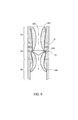
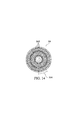
[0062]図1および図2は、ガス化装置の切欠き前方図を示す。この下方流ガス化装置は、連続する、並流の、重力アシスト式の、熱化学相変化のガス化装置であり、少なくとも3つの区域、熱分解区域20、酸化区域30および還元区域40を有する。ガス化装置は供給原料の一部を酸化させ、これにより残りの供給原料の熱化学固体から気体への相変化を開始するのに十分な熱活性化エネルギーを発生炉ガスへ放出する。ガス化の工程は、水の蒸発、リグニン分解、セルロース誘導体の爆燃および炭素還元を含めた一連の反応であり、一部が熱分解された供給原料に酸化剤ストリームを噴射することによって管理される。本発明は、バイオマスを処理するための方法および装置の文脈において記載されるが、記載される原理は、多くの他の種類の供給原料に適用されてよく、種々の実施形態が当業者にとって容易に明らかになるであろう。
[0062] FIGS. 1 and 2 show cutaway front views of a gasifier. The downflow gasifier is a continuous, co-current, gravity assisted, thermochemical phase change gasifier having at least three zones, a
[0063]ガス化装置全体の内部は、炭化ケイ素、酸化ケイ素、酸化アルミニウム、耐熱合金、他のセラミックまたは高温で安定性のある同様の特性を有する別の物質によってライニングされる。非揮発性およびガス化されない物質は、このような物質がガス化装置の底部に落下する際に重力によって発生炉ガスから分離される。このような高い効率のガス化装置は、供給原料の化学的な潜在エネルギーを発生炉ガスへ変換し、生成されるバイオ炭の平均的な量は元の供給原料の重量のおよそ1%〜10%である。 [0063] The interior of the entire gasifier is lined with silicon carbide, silicon oxide, aluminum oxide, refractory alloys, other ceramics or another material that has similar properties that are stable at high temperatures. Non-volatile and non-gasified materials are separated from the generator gas by gravity as such materials fall to the bottom of the gasifier. Such a high efficiency gasifier converts the chemical potential energy of the feedstock into generator gas, and the average amount of biochar produced is approximately 1% to 10% of the weight of the original feedstock. %.
[0064]図3および図4は、ガス化装置の外側の前方および側面図を示す。供給原料は、ガス化が行なわれる際、ガス化装置内を下方に移動する。ガス化装置が安定した作動状態に達したとき(すなわち、ガス化装置の各々の区域が安定した持続温度に達したときの状態)、ガス化装置の内部で垂直方向の温度勾配が形成され、供給原料が、ガス化工程におけるステップに基づいて熱分解区域20、酸化区域30および還元区域40に大まかに対応する一連の層または区域に層を成す。これらの区域の間には固定された境界はないが、代わりに境界には切れ目がない。したがって、各々の隣接する区域の混ざり合った特性を有する過渡的な勾配が存在する(すなわち、供給原料の熱分解は乾燥区域10で始まり、酸化は、熱分解区域20で始まってよい)。供給原料は、熱分解区域20より上のレベルに維持され、重力によって熱分解区域20を通り抜けて下方に引っ張られることで、下降する供給原料が、ガス化された供給原料に取って代わる。ガスおよび供給原料が、ガス化装置の内部を下方向に流れる。固体物質が、重力によってガス化装置の中を流れる。ガスは、圧力差によってガス化装置内を下方に移動する。
[0064] FIGS. 3 and 4 show a front and side view of the outside of the gasifier. The feedstock moves downward in the gasifier when gasification is performed. When the gasifier reaches a stable operating condition (ie, when each zone of the gasifier reaches a stable sustained temperature), a vertical temperature gradient is formed inside the gasifier, The feedstock is layered into a series of layers or zones that roughly correspond to
[0065]固体(例えば供給原料およびバイオ炭)は、図1、図2、図3および図4に示されるようにガス化装置の還元区域40の直ぐ下に配置された垂直方向に調節可能な回転式の火格子50によってガス化装置の内部に保持される。ガス化装置内での固体の滞在時間は、火格子50の回転速度、火格子50の垂直方向の位置およびガス化装置内でのガス化の速度(すなわち相変化)によって管理される。バイオ炭は火格子50の頂部に蓄積し、ガス化装置の底部のための見せかけのシールとして作用し、この見せかけのシールによってこのとき、ガス化装置が加圧することが可能になり、バイオ炭が継続的にガス化装置を出て行く際でも加圧を維持することが可能になる。バイオ炭は、回転式の火格子50またはバイパス49を通ってガス化装置の底部から落下する。ひとたびバイオ炭が火格子50またはバイパス49から落下すると、バイオ炭は、火格子50の下の1つまたは複数の収集シュート60に落下し、その後残留物ボックス90に落下し、そこでバイオ炭はオーガ91によってガス化装置から取り除かれる。
[0065] The solids (eg, feedstock and biochar) are vertically adjustable that are located directly below the
[0066]一実施形態において、ガス化装置の区域には、乾燥区域10、熱分解区域20、酸化区域30、還元区域40が含まれ、ガス化装置の下に配置された火格子50を備える。ガス化装置の下には、ガス収集ベント70、バイオ炭収集シュート60およびバイオ炭残留物ボックス90がある。
[0066] In one embodiment, the areas of the gasifier include a
[0067]図5および図6は、サイズが書かれた切欠き前方図および側面図を示す。 [0067] FIGS. 5 and 6 show a cut-out front view and a side view that are sized.
[0068]乾燥区域(任意選択の)
[0069]全体の説明、サイズおよび機能
[0070]乾燥区域10において、供給原料内の水分が、それが酸化区域30から放出する放射熱に曝される際に蒸発する。水蒸気は、熱分解区域20を通って酸化区域30に向かって、ガス化装置内に供給されるベッド酸化剤ストリームおよびパージ酸化剤ストリームと共に下方に流れる。乾燥区域10における温度は、ガス化装置が作動されるやり方に応じて極めて広範囲にわたって変動し得る。一例として、25%の水分含有量を有する木材チップの場合、乾燥区域10における通常の温度範囲は、およそ華氏100°から300°である。一実施形態における乾燥区域10の深さは、ゼロから6フィートの長さであってよい。この深さは、供給原料の水分含有量、ガス化装置のサイズおよび使用されるガス化装置の実施形態と共に増大する場合がある。酸化区域30からの放射熱は、この蒸発工程を進める。しかしながらベッド酸化剤ストリームおよびパージ酸化剤ストリームの事前加熱は、乾燥工程を加速させることができる。
[0068] Drying area (optional)
[0069] Overall description, size and function
[0070] In the drying
[0071]ガス化装置の内部の供給原料の乾燥作業は、吸熱性の工程であり、そのため供給原料を乾燥させ、蒸気として水を放出するのにエネルギー(すなわち熱)が必要とされ、この蒸気は下方で起こる反応を助ける。供給原料が湿っているほど、乾燥区域10はより多くのエネルギーを必要とする。
[0071] The drying operation of the feedstock inside the gasifier is an endothermic process, so that energy (ie heat) is required to dry the feedstock and release water as steam, this steam Helps the reactions that take place below. The wetter the feed, the more energy the drying
[0072]乾燥区域10における主な物理的な変化は、
[0073]H2O(l)+熱→Η2O(g)
[0074]「H」は水素であり、「O」は酸素であり、「l」は液体で「g」は気体である。
[0072] The main physical changes in the
[0073] H2O (l) + heat → Η2O (g)
[0074] “H” is hydrogen, “O” is oxygen, “l” is liquid, and “g” is gas.
[0075]供給機構および充填レベル指示器の説明
[0076]ガス化装置は作動中加圧されるため、圧力ロックを使用してガス化装置の圧力を維持しながら供給原料をガス化装置に入れる。圧力ロックの頂部弁が開放することで、供給原料が圧力ロック内に入るようにし、その後閉鎖する。圧力ロックの内部は、熱分解区域20(または任意選択で乾燥区域10)の空気圧と適合するように加圧し、これは底部弁が開放して供給原料が圧力ロックを離れ、調節後の空気圧でガス化装置に進入することを可能にするまでは制御システムを介してユーザによって管理されてよい。
[0075] Description of feed mechanism and fill level indicator
[0076] As the gasifier is pressurized during operation, a pressure lock is used to feed the feed into the gasifier while maintaining the gasifier pressure. The top valve of the pressure lock is opened, allowing the feed to enter the pressure lock and then closing. The interior of the pressure lock is pressurized to match the air pressure in the pyrolysis zone 20 (or optionally the drying zone 10), which opens the bottom valve so that the feed leaves the pressure lock and adjusts the air pressure. It may be managed by the user through the control system until it is possible to enter the gasifier.
[0077]圧力ロックは、スケジュール40のシームレス炭素鋼配管、150ポンドクラスの鋼のフランジおよび標準的な150ポンドクラスのスライドゲート弁、例えばナイフゲート弁などの材料から作製されてよい。この圧力ロック組立体は、その設備設計に組み込まれ、一対の標準的な工業用ナイフゲート弁をこれらの弁の間の配管と共に使用することができる。一実施形態における配管は、垂直方向に配向された18インチのスケジュール40の配管であってよい。配管の長さは、供給原料送達法および所望される容積に応じて調節することができる。圧力ロックの一例は、72インチの長さであり、この圧力ロックは、乾燥区域10(適用可能ならば)または熱分解区域20に空けられる供給原料当たり100〜120ポンドの供給原料を提供することになる。一実施形態において配管には、(1)回転レベルスイッチ、リミットスイッチ、フォトンスイッチまたはレーザスイッチなどのレベルスイッチおよび(2)圧力送信機および(3)加圧空気供給ラインを受けるためにねじ込み式継手が装着される。
[0077] The pressure lock may be made from materials such as
[0078]エンドユーザは、ガス化装置の供給原料充填工程をタイマーによって、あるいはマイクロ波センサまたは別の好適な充填レベル指示器を使用して自動化することで、ガス化装置およびまた圧力ロック(「充填レベル指示器」)における充填レベルでの供給原料の存在を検知することができる。ガス化装置の乾燥区域10は、高温環境で機能することが可能な1つまたは複数の充填レベル指示器12を有する場合がある。充填レベル指示器12がひとたび供給原料のレベルが低いことを検知すると、自動供給機構が始動する。複数の充填レベル指示器12を備えるガス化装置の設計によって、自動充填システムを利用する際、供給原料ベッドの高さを選択する際のより多くの選択肢が可能になる。
[0078] The end user automates the gasifier feedstock filling process with a timer or by using a microwave sensor or another suitable fill level indicator, thereby allowing the gasifier and also the pressure lock (" The presence of the feed at the filling level in the filling level indicator ")" can be detected. The drying
[0079]一実施形態において、圧力ロックの頂部弁が開放し、バケット荷重機構が、圧力ロック内の充填レベル指示器がそれが一杯であることを検知するまで供給原料を圧力ロックに空ける。圧力ロックの頂部弁が閉鎖し、圧力ロックは、乾燥区域10(適用可能ならば)または熱分解区域20の圧力に適合するように加圧する。その後、圧力ロックの底部弁が開放し、乾燥区域10(適用可能ならば)または熱分解区域20に接続された加圧オーガに供給原料を堆積させる。オーガはその後、ガス化装置の頂部に供給原料を堆積させる。ガス化装置の制御システムは、ガス化装置にある種々のセンサまたは指示器から受信した例えば温度または圧力変化などの信号に基づいて各々の供給原料充填サイクルをいつ起動するかを判断する。
[0079] In one embodiment, the top valve of the pressure lock opens and the bucket load mechanism empties the feedstock to the pressure lock until the fill level indicator in the pressure lock detects that it is full. The top valve of the pressure lock closes and the pressure lock pressurizes to match the pressure in the drying zone 10 (if applicable) or
[0080]熱分解区域
[0081]包括的な、サイズおよび機能
[0082]熱分解区域20は、ガス化装置内で乾燥区域10(乾燥区域10が含まれているならば)の真下にある。熱分解区域20は、予想される供給原料の最も多数の種類の特性に基づいて高さを上げたり下げたりする場合がある。より高い位置の熱分解区域20は、より多くの乾燥作用およびより長い熱分解時間を必要とするより湿ったおよび/またはより複合的な材料を収容する。
[0080] Pyrolysis zone
[0081] Comprehensive size and function
[0082] The
[0083]熱分解区域20において、蒸気、油分および構成ガスが蒸留され、重力、圧力差ならびに乾燥区域10および熱分解区域20内で生じる蒸気の作用によって下方に移動する。熱分解区域20は、頂部において吸熱性であり、下流から放出される熱に依拠している。熱分解区域20の底部に向かって、ここでは温度が上昇するが、供給原料は、それが上昇した温度において化学的に不安定になるため、ひとりでに分解し始める。したがって熱分解区域20のより下方のセクションで生じる供給原料の分解は、発熱性であり熱を放出する。一実施形態において、熱分解区域20は4から6フィートの深さである。
[0083] In the
[0084]熱分解化学は、極めて複雑である。このような区域において生じる最も重要な化学的および物理的な変化は、以下のように簡略化され表すことができる。
[0085]CxHyOz(s)+熱→有機蒸気(ホルムアルデヒド、アルコール、タールなど)
[0086]CxHyOz(s)→CH4+H2+C(s)+有機蒸気(タール)+熱
[0084] Pyrolysis chemistry is extremely complex. The most important chemical and physical changes that occur in such areas can be simplified and represented as follows.
[0085] CxHyOz (s) + heat → organic vapor (formaldehyde, alcohol, tar, etc.)
[0086] CxHyOz (s) → CH 4 + H 2 + C (s) + organic vapor (tar) + heat
[0087]ガス化装置に供給される酸化剤ストリームからの一部の酸素は熱分解区域20内に存在するため、酸化は、供給原料が熱分解区域20の底部に接近する際に生じる可能性がある。
[0087] Because some oxygen from the oxidant stream fed to the gasifier is present in the
[0088]酸化区域
[0089]包括的な説明、サイズおよび機能
[0090]酸化区域30は、酸化帯域350までまたは酸化帯域350から離れるようにつながるガス化装置内の区域である、あるいは酸化帯域350の形成を含めた方法の一般的なステップである。酸化区域30は、酸化帯域350が形成され、ガス化工程における最も高温のステップを表す場所であり、供給原料のセルロース誘導体の一部が、固体から気体に変換する場所である。
[0088] oxidation zone
[0089] Comprehensive description, size and function
[0090]
[0091]第1の傾斜(誘導された供給原料の傾斜)
[0092]図7および図8に示される作動中の熱分解区域20を通る酸化剤ストリームの流れは、(1)垂直方向に、熱分解区域20の外壁の頂部に向かって始まり、酸化区域30における平面空気入口32の下方リングにおいて下方に終端する、および(2)水平方向に、ガス化装置の中心で始まり、ガス化装置の壁において終端する(「誘導された供給原料の傾斜」)を形成するように供給原料の傾斜を誘導する。
[0091] First slope (induced feedstock slope)
[0092] The flow of the oxidant stream through the
[0093]図7、図8、図9および図10に示されるように、このような誘導された供給原料の傾斜は、ガス化装置の壁の周囲に向かっておよび酸化帯域350より上で(「最も密度が高い部分」)より高密度になる増大する供給原料の密度差であり、一斉に作用する少なくとも4つの要因、すなわち(1)ガス化装置の内壁に対して供給原料を押しつける酸化帯域酸化帯域350からの圧力波、(2)熱分解区域20および酸化区域30の幾何学形状(すなわち壁の角度)、(3)熱分解区域20および酸化区域30に流れ込む酸化剤ストリームの総体積、および(4)熱分解区域20および酸化区域30各々に流れ込む酸化剤ストリームの相対的な体積によって形成される。誘導された供給原料の傾斜の最も高密度の部分は、200で示されている。
[0093] As shown in FIGS. 7, 8, 9 and 10, the gradient of such induced feedstock is directed toward the perimeter of the gasifier wall and above the oxidation zone 350 ( “The most dense part”) is an increasing feed density density difference that becomes denser and has at least four factors that work together: (1) an oxidation zone that presses the feed against the inner wall of the gasifier Pressure waves from
[0094]供給原料は、異なる速度でガス化装置を通り抜けて進む。供給原料の一部は、ガス化装置流れレーン203内をガス化装置を下方に着実に進んでいき、他の供給原料は、ガス化装置内の種々の地点において一時止まったり、減速する場合もある。供給原料は、誘導された供給原料の傾斜200においてよりゆっくりと移動するおよび/または一時中断する。誘導された供給原料の傾斜200における最も高密度の部分は、ガス化装置流れレーンにおける供給原料よりも密度が高く、かつよりゆっくりと移動する供給原料である。
[0094] The feedstock proceeds through the gasifier at different rates. Some of the feedstock may steadily progress down the gasifier in the
[0095]誘導された供給原料の傾斜200における最も高密度の部分は、酸化区域30がより広い直径に広がる下方の平面空気入口32において終端する。一実施形態において、この拡張は、ガス化装置を下方に移動する気体および固体の流速を誘導し管理するためにKline−Fogelman段になるように設計される。
[0095] The densest portion of the induced
[0096]通常は、気体がKline−Fogelman段などの特定の段を横切る際、渦が形成される。酸化区域30における平面空気入口32の下方リングが、そうでなければ渦が形成されるであろう場所に空気を噴射する。このような進入する空気ストリームは、発生炉ガスおよびガス化装置流れレーン203を下方に進入する供給原料と衝突し、高温ガスをガス化装置の壁から離れるように誘導し直し、渦の形成を妨げ、酸化帯域350に燃料を補給する。
[0096] Normally, vortices are formed when a gas crosses a particular stage, such as a Kline-Fogelman stage. The lower ring of the
[0097]ガス化装置における条件が変化する際、誘導された供給原料の傾斜はまた、ガス化装置の内部で酸化帯域350およびガス化装置流れレーン203の移動を可能にする。これは、ガス化装置流れレーン203がガス化装置の動かない外壁に対して形成される場合の他のガス化装置では不可能である。
[0097] As conditions in the gasifier change, the induced feedstock gradient also allows for movement of the
[0098]酸化帯域
[0099]図9および図10に示されるガス化装置流れレーン203における供給原料は、ガス化装置を通って酸化帯域350に入るように下方に進む。酸化帯域350は、供給原料内のセルロース誘導体物質の爆燃によって有意な熱が解放される地点である。始動時にひとたび始動されると、酸化帯域350は、平面空気入口31、32からの追加の酸化剤ストリームと、上から下降する供給原料とによって維持される。酸化帯域350は供給原料の一部をバイオ炭と発生炉ガスの構成ガスに酸化する。熱分解区域20において生成されるタール蒸気はさらに、酸化帯域350の高温の下で蒸気がある状態で追加の発生炉ガスへ分解される。
[0098] Oxidation zone
[0099] The feedstock in the
[00100]図7、図8、図9および図10に示されるように、酸化区域30の全体の形状は中空の管であり、この管は、おおよそ同一のサイズであるが中央302において広げられた入口301と、出口303とを有する。これは、酸化区域が空塔速度理論に従って制限地点へ狭くなる従来の下方流ガス化装置とは反対である。
[00100] As shown in FIGS. 7, 8, 9 and 10, the overall shape of the
[00101]一実施形態において、酸化区域30の入口301および出口303は、酸化区域30の広げられたセクションの半分の直径である。平面空気入口31、32の少なくとも2つのリングがある。一実施形態において、高い方のリング31は、下方リング32よりおおよそ11インチ上にあり、平面空気入口32の下方リングは、酸化区域30の広げられたセクション302の最も広い部分にある。
[00101] In one embodiment, the
[00102]このような酸化帯域350によって生じる極めて高い温度は、熱分解区域20およびそれより上の乾燥区域10(適用可能であるならば)において化学および物理的反応を進める熱を生み出す。酸化帯域350は元々、消費されない供給原料および上の酸化剤ストリーム供給源に向かってガス化装置内を上向きに移動する傾向がある。酸化帯域350の下にバイオ炭の混合体があり、これは高温で比較的安定している。ガス化装置は、酸化帯域350がガス化装置内を上下に移動することが可能であるように設計される。一実施形態において、酸化帯域350は、上向きに移動する酸化帯域350の傾向を抑制するように、酸化帯域350の下のバイオ炭を取り除くための火格子50(還元区域40の下に配置される)を利用してガス化装置内の所定の場所に保持される。火格子50が回転する度に、酸化帯域350は上昇し始める。
[00102] The extremely high temperature generated by such an
[00103]一実施形態において、平面空気入口32の下方セットより上に配置された平面空気入口31の高い方のリングによって、供給原料が酸化帯域350に進入する直前に追加の酸化剤ストリームを供給原料に噴射することが可能になる。火格子50の回転速度、ベッド酸化剤ストリーム、パージ酸化剤ストリームおよび可動酸化剤ストリームの速度および比率を利用して、酸化帯域350をガス化装置内の任意の所望の場所に保持することができる。一実施形態において、酸化帯域350は、平面空気入口32の直ぐ下に保持される。
[00103] In one embodiment, the higher ring of the
[00104]供給原料の部分酸化もまた複雑であるが、以下の式に簡略化することができる。
[00105]供給原料−範囲C+1/2O2→CO+熱
[00106]供給原料−範囲C+O2→CO2+熱
[00107]供給原料−範囲H+O2→H2O+熱
[00108]供給原料−範囲H→H2
[00109]CO+3H2→CH4+H2O+熱
[00110]CO2+4H2→CH4+2H2O+熱
[00111]固体C残留物+2H2→CH4+熱
[00112]CO+H2O→C02+H2+熱
[00104] Partial oxidation of the feedstock is also complex but can be simplified to the following equation:
[00105] Feedstock-Range C + 1 / 2O2-> CO + Heat
[00106] Feedstock-Range C + O2-> CO2 + Heat
[00107] Feedstock-Range H + O2-> H2O + Heat
[00108] Feedstock-Range H → H2
[00109] CO + 3H2-> CH4 + H2O + heat
[00110] CO2 + 4H2 → CH4 + 2H2O + heat
[00111] Solid C residue + 2H2 → CH4 + heat
[00112] CO + H2O → C02 + H2 + heat
[00113]酸化区域30における反応は、発熱性であり、ガス化装置全体を作動する熱を放出する。
[00113] The reaction in the
[00114]第2の傾斜(流入したバイオ炭の傾斜)
[00115]図7、図8、図9および図10に示されるように、酸化帯域350の直ぐ下で、第2のバイオ炭の傾斜の始まりが、(1)垂直方向に、酸化区域30内の平面空気入口32の下方リングの直ぐ下で始まり、酸化区域30の壁に沿って還元区域40に下方に延び、(2)水平方向に、ガス化装置の中心からガス化装置の壁に(「流入したバイオ炭の傾斜」)形成される。バイオ炭が酸化帯域350を離れる際、酸化区域30の直径は、酸化区域30に対する入口301とおおよそ同一のサイズまで狭まる。酸化帯域からの圧力波が、バイオ炭を酸化区域の狭まる壁に対して押しつける。流入したバイオ炭の傾斜の最も高密度の部分は300で示される。圧力波が、ガス化装置流れレーン203内にバイオ炭に対して、流入したバイオ炭の傾斜300における最も高密度の部分の移動を遅くする。ガス化装置流れレーン203は、供給原料が相を変えたとしてもそのままの状態であり、発生炉ガスおよびバイオ炭がここでは、供給原料の代わりに下方に移動する。
[00114] Second slope (inclined biochar slope)
[00115] As shown in FIGS. 7, 8, 9, and 10, immediately below the
[00116]流入したバイオ炭の傾斜300の最も高密度の部分は、酸化区域30の壁に沿って還元区域40に下方に伸びる。還元区域40は、酸化区域30より幅が広いため、還元区域40への入口は別の工程を形成する。一実施形態において、酸化区域30の角度付きの壁と還元区域40への入口が、Kline−Fogleman段を形成する。発生炉ガスがこの段を横切りより広い還元区域40(すなわち還元区域40における直径の拡張部)に入る際、還元区域40に渦が形成される。この渦は、還元区域40における発生炉ガスとバイオ炭の混合作用を促進させる。
[00116] The densest portion of the
[00117]炉頂と炉床のシミュレーション
[00118]従来の下方流ガス化装置とは異なり、この下方流ガス化装置は、酸化区域30内に制限区域を持たないが、代わりに酸化区域30は、サイズが大きくなる。ほとんど全ての下方流ガス化装置は、空塔速度理論を適用するため、よって使用できる品質の発生炉ガスを実現するために酸化区域30における制限部を有するように構築される。加えて、大半の下方流ガス化装置は、真空を利用して、ガス化装置を通るように発生炉ガスを引き込む。
[00117] Simulation of hearth and hearth
[00118] Unlike conventional downflow gasifiers, this downflow gasifier does not have a restricted area within the
[00119]このようなガス化装置において形成される2つの傾斜、すなわち酸化帯域350より上の誘導された供給原料の傾斜と、酸化帯域350より下の流入したバイオ炭の傾斜は、協働して作用して、ガス化装置の内部の炉頂と炉床をシミュレートする。この手法の利点は、酸化帯域350を、ガス化装置自体を損傷したり場合によって壊したりせずに、ガス化装置内で上下に移動させることができ、ガス化装置の内部で、異なる種類の供給原料および供給原料の混合体を採用することができる点である。固定式の炉頂と炉床を備えた他のガス化装置は、狭い範囲の供給原料に対して較正する必要があり、他の種類の供給原料を収容するために容易に調節することができず、変化に対応するために作動中に調節することもできない。
[00119] The two slopes formed in such a gasifier, namely, the slope of the induced feedstock above the
[00120]還元区域
[00121]包括的な説明、サイズおよび機能
[00122]図1、図2、図7および図8に示されるように、ガス化装置の還元区域40は、酸化区域30の出口303と等しい、またはこれより大きな直径である。還元区域40の2つの主な機能は、バイオ炭からの残りの炭素をガス化し、発生炉ガスを冷却することである。これらの機能は共に、同一の機構によって生じ、すなわち、発生炉ガス構成要素と、バイオ炭に含まれる固体炭素との吸熱性の反応である。
[00120] Reduction area
[00121] Comprehensive description, size and function
[00122] As shown in FIGS. 1, 2, 7, and 8, the
[00123]上記で考察したように、発生炉ガスおよびバイオ炭が還元区域40に進入する際、酸化区域30の出口303と、より幅広の還元区域40との間の段を横切るように乱流の渦が形成される。還元区域40におけるこの乱流によって、還元区域40において他のガス化装置設計よりはるかに優れた発生炉ガスとバイオ炭の混合作用が起こる。これによりベッド内の炭素のほぼ完璧なガス化が可能になり、冷却作用を最大にすることができる。一実施形態においてガス化装置の還元区域40は、火格子50より上でおよそ2から6フィートのバイオ炭のベッドを維持する。
[00123] As discussed above, turbulent flow across the stage between the
[00124]発生炉ガスは、華氏1500°以上辺りの温度で典型的な下方流ガス化装置を出て行く。発生炉ガスは、このガス化装置を華氏1500°未満の温度で出て行く。一実施形態において、発生炉ガスは、華氏1000°未満で出て行く。また、厚みのあるバイオ炭のベッドによって、供給原料に応じておよそ90から99%の燃料炭素が発生炉ガスとしてこのガス化装置を出て行くことが可能である。 [00124] The generator gas exits a typical downflow gasifier at a temperature around 1500 degrees Fahrenheit. The generator gas exits the gasifier at a temperature of less than 1500 ° Fahrenheit. In one embodiment, the generator gas leaves at less than 1000 degrees Fahrenheit. Also, a thick bio-char bed allows approximately 90 to 99% of the fuel carbon to exit the gasifier as the generator gas, depending on the feedstock.
[00125]下方流ガス化装置において生じる還元反応は、十分に研究されており、以下を伴うように理解される。
[00126]炭素+CO2+熱→2CO
[00127]炭素+H2O+熱→CO+H2
[00128]炭素+2H2O+熱→CO2+2H2
[00129]CO2+H2+熱→CO+H2O
[00125] The reduction reactions occurring in downflow gasifiers are well studied and are understood to involve the following.
[00126] Carbon + CO2 + heat → 2CO
[00127] carbon + H2O + heat → CO + H2
[00128] carbon + 2H2O + heat → CO2 + 2H2
[00129] CO2 + H2 + heat → CO + H2O
[00130]ガス化装置火格子
[00131]ガス化装置の火格子50は、ステンレス鋼、または耐久性があり、かつ耐熱性で熱に反応しない炭化ケイ素、酸化ケイ素、酸化アルミニウム、耐熱合金、他のセラミックなどの別の好適な物質で作製されてよく、火格子は頂部面と、底部面とを有する。一実施形態において、かつ図3および図4に示されるように、火格子の底部面およびシャフトは、上下に移動し、調節可能な制御システムによって管理される上昇する台80の上に設置されてよい。図3および図4に示されるように、火格子50の頂部面は、還元区域40の下方縁部の下に配置される。一実施形態において、バイパスは、還元区域40と、火格子50の頂部面との間にある2.5から2インチの隙間である。
[00130] gasifier grate
[00131] The
[00132]らせん状の溝
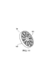
[00133]図11は、ガス化装置内の固体の全てに対して支持を提供するガス化装置の火格子50を示している。一実施形態において、火格子50は、フレーム505と、2つの面、すなわち頂部面および底部面とを有する。
[00132] spiral groove
[00133] FIG. 11 shows a
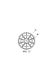
[00134]図11および図12は、らせん状の溝501を有する火格子50の頂部面を示している。らせん状の溝501は、この溝が還元区域40に面するようにガス化装置内で配向される。らせん状の溝501は、火格子の中心にある開始地点と、火格子50の縁部に対して外向きに続く末端とを有する。したがって一実施形態において、らせん状の溝は、火格子の頂部面全体に及ぶ。らせん状の溝501の目的は、この溝は元々、火格子50がらせん状の溝501の方向と反対に回転する際、バイオ炭を火格子50の中心から外向きに火格子50の縁部に向けて移動させることである。バイオ炭は、火格子50が反対方向に回転する際、バイオ炭がバイパスを通って還元区域40から押しやられるまでらせん状の溝501の末端に従う。
[00134] FIGS. 11 and 12 show the top surface of a
[00135]還元区域40の一実施形態において、炭化ケイ素、酸化ケイ素、酸化アルミニウム、耐熱合金、他のセラミック、または任意の他の耐熱性で高密度の層物質が、還元区域40の壁をライニングする。この耐熱性で高密度の層物質は、回転する火格子50によって還元区域40の外壁に対して押しつけられこの外壁に沿って引きずられるいかなるバイオ炭も絶えず粉砕するやすりとして作用する。火格子内にらせん状の溝50を有し、バイオ炭を還元区域40の層壁に向かっておよび層壁に沿って押しやるこのような組み合わせは、大きな塊の炭化物をバイパスに逃げる十分に小さい破片に粉砕する助けをする。当業者は、異なる種類のらせん(例えばアルキメデス原理の、対数などの)が使用され得ることを理解するであろう。
[00135] In one embodiment of the
[00136]一実施形態において、火格子内のらせん状の溝501は「v」字形のアルキメデス原理の溝502であり、この場合、らせんの中の1つの溝の外縁部は、隣接する溝の内縁部と合わさって隆起した縁部を形成する。「v」字形の溝の目的は、いかなる90°の角度も有することを回避することであり、90°の角度は、そうでなければホットスポットまたは火格子50の熱的に不安定なセクションを形成することになる。
[00136] In one embodiment, the
[00137]火格子/バイパスの昇降
[00138]一実施形態において、火格子50は、昇降させることで、より高いまたはより低いバイパスを形成することができ、意図せずにガス化装置に進入したより大きな物質および/またはガス化されない物質を(煉瓦状の塊、石など)ガス化装置を停止させずに取り除くことが可能になる。火格子50内にらせん状の溝501を備える一実施形態において、このような異物は還元区域40の壁に対して押しやられ、その後、これらの異物をバイパスを介して排出することができるように火格子50を下げることができる。このような設計によって、ガス化装置を使用中の状態に維持し、さらには大きなガス化されない物体を還元区域40から取り除くことが可能になる。火格子50を昇降させる能力はまた、メンテナンスが絶えずガス化装置の内部で必要とされる場合にも利用することができる。加えて、バイパス49は、還元区域40から出る発生炉ガスの流れを制御するように機能し、バイパス49は、弁と同様に作用する。例えば短いバイパスは、火格子50を通り抜ける発生炉ガスの流れに対する抵抗を高め、圧力がガス化装置内で高まるようにする。
[00137] Grate / Bypass Lift
[00138] In one embodiment, the
[00139]火格子の中の楕円形の穴
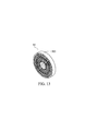
[00140]図13および図14は、組み立て後の火格子を示している。図15および図16は、火格子の「パイ状のスライス」のセグメント502を示している。図13および図14は、楕円形の穴503を有する組み立て後の火格子の斜視図および前方図を示す。一実施形態において、楕円形の穴503は、例えば腎臓形状または長円形の穴であり、火格子50全体にわたって対称的に分散される(但し、火格子を持ち上げ回転させる機械的な軸より上の火格子の中心には穴がない)。穴503の目的は、バイオ炭および発生炉ガスの両方が火格子を通り抜けてその下のバイオ炭収集シュート60に入ることを可能にすることである。
[00139] Oval hole in grate
[00140] FIGS. 13 and 14 show the grate after assembly. 15 and 16 illustrate a “pie slice”
[00141]火格子に対するパイ状のスライスインサート
[00142]一実施形態において「パイ状のスライス」のセグメント502、504は、火格子50のフレーム505の上に置かれる。セグメント504の各々がフレーム505内に挿入されたとき、火格子が形成される。この実施形態によって、火格子50の一部が損傷した場合、火格子50全体ではなくセグメント504を交換することが可能になり、またガス化装置を、特定の種類の供給原料用に設計されたカスタマイズされたセグメント504と適合させることも可能になる。
[00141] Pie slice inserts for grate
[00142] In one embodiment, "pie slices"
[00143]複数の特徴を備えた火格子
[00144]図15は、火格子の取り外し可能の部分の斜視図である。一実施形態において、火格子50はまた、「v」字502として切り取られたらせん状の溝501と、らせん状の溝501を切り開いた腎臓の形状または長円形の穴503とを有する。図16は、火格子の取り外し可能の部分の頂面図を示す。
[00143] Grate with multiple features
[00144] FIG. 15 is a perspective view of the removable portion of the grate. In one embodiment, the
[00145]火格子を利用するガス化装置の制御
[00146]火格子50を支持し回転させるシャフトを火格子50のサイズに応じて1つまたは複数の部品で形成することができる。火格子50の回転速度は、制御システムによって較正することができるが、典型的には、供給原料の不揮発性の成分および発生炉ガスの生成速度に応じて0.0001RPMから1RPMの範囲である。酸化帯域350は、還元区域40内のバイオ炭のベッドの頂部に事実上乗っているため、還元区域40内のバイオ炭のベッドが厚くなりすぎた場合、酸化帯域350は、熱分解区域20に入るように上昇することになる。熱電対または他のセンサを使用して酸化帯域350の場所を監視することで、以下で考察されるガス化装置の制御システムは、火格子50の回転の速度を上げ、より高速でバイオ炭を除去するようにプログラミングすることができ、これによりバイオ炭ベッドの高さを下げ、酸化帯域350を適切な場所に戻るように下げる。逆に、ガス化装置の制御システムは、バイオ炭のベッドが浅くなりすぎた場合、その結果酸化帯域350が火格子に対して近づきすぎるほど移動した場合、火格子50を減速させることができる。
[00145] Control of gasifier using grate
[00146] The shaft that supports and rotates the
[00147]炭化物収集シュート
[00148]図1、図2、図5および図6に示されるように、ガス化装置の下には、バイオ炭収集シュート60があり、これは鋼、ステンレス鋼または別の頑丈で、熱安定性であり、小孔のない物質で作製されてよい。バイオ炭が火格子50の底部または側部から出る際、バイオ炭は、ガス化装置の下にあるバイオ炭収集シュート60に下方に落下する。バイオ炭収集シュート60は、ガス化装置流れレーン203内でのバイオ炭の流れの方向から特定の角度のところに配置される。一実施形態においてこの角度は、ガス化装置流れレーン203におけるバイオ炭の流れの方向から測定して90°未満である。一実施形態において、この角度は、ガス化装置流れレーン203におけるバイオ炭の流れの方向から測定して45°から80°である。一実施形態において、少なくとも2つのバイオ炭収集シュート60がガス化装置の中心軸に対して対称的に配置される。
[00147] Carbide collecting chute
[00148] Below the gasifier is a
[00149]発生炉ガス収集ベント/ホーン
[00150]図1、図2、図5および図6に示されるように、2つ以上の発生炉ガス収集ベント70が火格子50の軸線の周りに対称的になるようにバイオ炭収集シュート60内に配置される。発生炉ガス収集ベント70に対する開口は、下方に向いており、そのためバイオ炭は、バイオ炭が火格子50から落下する際、これらのベントの中に直接落下しない。発生炉ガスおよびバイオ炭がバイオ炭収集シュート60に入るように落下する際、重力によってバイオ炭が発生炉ガスから分離され、発生炉ガスは、発生炉ガス収集ベント70を通って出て行く。
[00149] Generator gas collection vent / horn
[00150] As shown in FIGS. 1, 2, 5, and 6, the
[00151]バイオ炭残留物ボックス
[00152]図6に示されるように、バイオ炭残留物ボックス90が、バイオ炭収集シュート60の底部にある。バイオ炭は、バイオ炭収集シュート60を下方に落下してバイオ炭残留物ボックス90に入る。
[00151] Bio charcoal residue box
[00152] A
[00153]バイオ炭残留物ボックスは、「残留物オーガ」と呼ばれる管形式のオーガ91を有する。残留物オーガ91は、残留物オーガ91にボルト締めされた十字型のスプール配管の端部にボルト締めされたポケット弁92に入るようにバイオ炭を移動させる。一実施形態において、ポケット弁92は、標準的な空気始動式の8インチまたは10インチのボール弁であり、この場合ボール弁は一端において密閉される。「上の」位置において、ボールはバケットを形成する。残留物オーガ91は、ガス化装置の制御システムによって制御されるため、ポケット弁92が上の位置にあるとき、残留物オーガ91は、バイオ炭をポケット弁92の中に堆積させる。制御システムがこの工程を停止する際、残留物オーガ91は停止し、ポケット弁92は、「下」の位置に回転し、その内容物を外部の収集箱または何らかの他の二次的な除去システムに空ける。ポケット弁92にあるボールは、一端において閉鎖されるため、ポケット弁92は、常に密閉された状態であり、発生炉ガスがバイオ炭残留物ボックス90から漏れ出すのを防ぐ。少量の発生炉ガスが漏れるが、高い地点のベント配管によって安全に排気される、あるいは真空ポンプによって吸い出すことができる。
[00153] The biochar residue box has a
[00154]供給原料の要件
[00155]ガス化装置は、極めて広範な範囲の供給原料をガス化することができる。所与の供給原料または材料の混合物が有効にガス化するかどうかを判断するために、供給原料は、酸化剤ストリームが供給原料の中を通ることができるように十分に多孔性であり、好適な発熱密度(btu/ft3)を有し、好適なかさ密度および好適な化学的組成を有する必要がある。当業者は、好適な供給原料を認識するであろう。ガス化装置の一実施形態において、好適な供給原料は、(1)25%以上の化学結合した酸素含有量(分子ベースの)、(2)10%以下の灰の含有量、(3)30%以下の水分含有量、および(4)15lbs/ft3を超えるかさ密度であってよい。これらの変量には何らかの相互作用がある。
[00154] Feedstock requirements
[00155] The gasifier can gasify a very wide range of feedstocks. In order to determine whether a given feedstock or mixture of materials effectively gasifies, the feedstock is sufficiently porous and suitable to allow the oxidant stream to pass through the feedstock. Heat generation density (btu / ft3), suitable bulk density and suitable chemical composition. Those skilled in the art will recognize suitable feedstocks. In one embodiment of the gasifier, suitable feedstocks are: (1) 25% or more chemically bonded oxygen content (molecular basis), (2) 10% or less ash content, (3) 30 % Moisture content and (4) bulk density greater than 15 lbs / ft3. There is some interaction between these variables.
[00156]全てのバイオマスの形態はCxHyOzの基本的な化学構造を含む。この分子構造は本来、上昇した温度では不安定であり、加熱される際、容易に分解する。これは、全てのタイプのバイオマスガス化装置の基本的な駆動体である。この分子の分解は、高度に発熱性であり、さらなるバイオマスの分解を持続するのに必要な熱を生成する。したがって実際には全ての形態のバイオマスは、それらが多孔性およびかさ密度要件を満たすことを条件でガス化装置に適した供給原料である。 [00156] All biomass forms contain the basic chemical structure of CxHyOz. This molecular structure is inherently unstable at elevated temperatures and easily decomposes when heated. This is the basic driver for all types of biomass gasifiers. This molecular degradation is highly exothermic and produces the heat necessary to sustain further biomass degradation. Thus, in practice all forms of biomass are suitable feedstocks for gasifiers provided they meet the porosity and bulk density requirements.
[00157]始動および停止
[00158]始動時に、ガス化装置は、酸化区域30の中央まで供給原料で満たされる。高温の木炭の層(一実施形態において、ごく数インチの高さの層)が、熱分解区域20または乾燥区域10(適用可能ならば)の頂部を通って供給原料の頂部に適用される。ガス化装置は、この後、供給原料で満たされ、ガス化装置のレベル指示器およびガス化装置の制御システムが始動される。
[00157] Start and stop
[00158] At start-up, the gasifier is filled with feed to the middle of the
[00159]次の数時間にわたって、ガス化装置は加熱し始め、温度勾配が形成され始める。一部の低品質のガスが、ほぼ直ぐに形成され、発生炉ガス生成は、ガス化装置が加熱するにつれて、徐々に増大し、向上する。 [00159] Over the next few hours, the gasifier begins to heat up and a temperature gradient begins to form. Some low quality gas is formed almost immediately and the generator gas production gradually increases and improves as the gasifier heats.
[00160]ガス化装置が適切な期間にわたって作動されるならば、ガス化装置の内部のライニングは、たっぷりと熱を含むようになり、ガス化装置は、数時間のダウンタイムの後でも、追加の高温の木炭なしで再始動させることができる。これは、「ウォームスタート」と呼ばれる。多くの場合、ガス化装置は、2日から3日超の間停止させてもなお、単に酸化剤ストリームを再度開始することによってウォームスタートのために十分な内部熱を維持することができる。ガス化装置からの発生炉ガスの流れは、酸化剤ストリームが停止する際に停止する。 [00160] If the gasifier is operated for an appropriate period of time, the lining inside the gasifier will contain plenty of heat and the gasifier will add even after a few hours of downtime. Can be restarted without high temperature charcoal. This is called a “warm start”. In many cases, the gasifier can maintain sufficient internal heat for a warm start by simply re-initiating the oxidant stream, even if shut down for more than 2 to 3 days. The generator gas flow from the gasifier stops when the oxidant stream stops.
[00161]ガス化装置の制御システム
[00162]ガス化装置の作動の最適化は、酸化帯域350の場所を管理するために正確なリアルタイムの調節を必要とする。例えば出て行くまたは進入する物質の速度を調節するために機械的なデバイスが酸化帯域350内に挿入されるならば、酸化帯域350における華氏3,000°の温度(おおよそ)がこの機械的デバイスを破壊するであろう。したがって火格子50はさらにずっと低温の還元区域40に隣接するように配置させることができるため、火格子50を使用してガス化装置からのバイオ炭の除去を管理する。還元区域40からバイオ炭を除去率を上げることによって生じるバイオ炭ベッドの高さの変化は、酸化帯域350の垂直方向の位置を調節するために必要な何らかの変更を誘発する。以下で言及される変量は各々、酸化帯域350における変化を誘発するように調節することができる。
[00161] Gasifier control system
[00162] Optimization of gasifier operation requires precise real-time adjustments to manage the location of the
[00163]複数の方法およびシステムを制御システム全体の一部として利用することで、変化を誘発し、酸化帯域350を制御することができる。制御システムは、種々のアルゴリズムを利用して、ガス化装置を監視し調節する。制御システムは、リアルタイムの調節が可能であり、ガス化装置がオフラインにされる間のみ調節され得る他の方法を説明することが可能なサブシステムを含むことができる。ガス化装置がオフラインにされる間の調節には、(1)乾燥区域10の物理的サイズおよび高さの調節(または乾燥区域10を取り除く)、(2)火格子50の穴503のサイズの調節(一実施形態では、火格子50の互換性のあるセグメント504を交換することによって)が含まれてよい。制御システムは、(a)ガス化装置に進入する供給原料の種類、(b)供給原料がガス化装置に進入する速度、(c)適用可能な場合の乾燥区域10における供給原料の充填レベル、(d)適用可能な場合の乾燥区域10の温度、(e)熱分解区域20(または適用可能ならば乾燥区域10)の頂部における入口を介して送達される酸化剤ストリームの体積、速度および圧力、(f)平面空気入口31、32のリングを通って送達される酸化剤ストリームの体積、速度および圧力、(g)ガス化装置の全体の圧力、(h)ガス化装置の種々の区域における圧力差、(i)ガス化装置内での酸化帯域350の場所、(j)火格子50の回転速度の調節、(k)火格子50の垂直方向の位置(すなわちバイパスの高さの調節)、(l)還元区域40におけるバイオ炭ベッドの厚さ、(m)ガス化装置を出て行く発生炉ガスの構成成分のテストおよびサンプリング、(n)ガス化装置を出て行く発生炉ガスの温度、(o)発生炉ガス収集ベントの圧力およびガス化装置を出て行く発生炉ガスの圧力(上記の例は「可変」である)に関するガス化装置の作動中のリアルタイムの調節を実施するためにサブシステムを含むことができる。
[00163] Utilizing multiple methods and systems as part of the overall control system can induce changes and control the
[00164]可変の周波数駆動
[00165]ガス化装置の一実施形態において、制御システムは特定の変量を徐々に増加または低下させる、あるいは変量全体に対する何らかの変更を開始するまたは停止することができる。例えば、制御システムは、ある時点で火格子50の回転速度をわずかに遅くする必要があり、その後別の時点で火格子50を完全に停止させる必要がある場合がある。当業者は、電気モータおよび駆動装置が、一部が固定された速度の駆動装置であり、他方が可変の周波数(速度の)駆動装置(「VFD」)である2つの一般的な方法で作動することを理解するであろう。ガス化装置の一実施形態において、よってVFDは、オン/オフタイマーに装着され、火格子50の回転速度を制御するために利用される。VFDを始動および停止することによって、制御システムは、火格子50を回転するためにVFDからの十分なトルクを維持する一方で、低速の火格子50の回転をシミュレートすることができる。
[00164] Variable frequency drive
[00165] In one embodiment of the gasifier, the control system can gradually increase or decrease a particular variable, or initiate or stop any change to the entire variable. For example, the control system may need to slightly slow the rotational speed of the
[00166]より高いトルクが必要とされない酸化剤ストリーム制御システムなどの他の用途では、VFDは、オン/オフタイマーなしで利用される場合もある。 [00166] In other applications, such as oxidant stream control systems where higher torque is not required, the VFD may be utilized without an on / off timer.
[00167]火格子の管理
[00168]制御システムは、火格子50の回転速度を調節することで、酸化区域30と還元区域40との間の圧力差を含めた複数の変量を調節する。この後者の一例は、還元区域の圧力差が、単に火格子50のRPM設定を管理することによって維持され得ることである。
[00167] Grate management
[00168] The control system adjusts a plurality of variables, including a pressure difference between the
[00169]酸化剤ストリームの流れの制御
[00170]バイオ炭がガス化装置を出て行くときの速度はまた、ガス化装置にわたる垂直方向の圧力差も制御する(バイオ炭ベッドの厚さはガス化装置の圧力をある程度決定するが、これはバイオ炭がガス化装置の底部において見せかけのシールを形成するためである)。ガス化装置にわたる垂直方向の圧力差、すなわち乾燥区域10の頂部から火格子50の底部を通り抜ける圧力はよって、火格子50の回転速度を単に上下させ、これによりバイオ炭を還元区域40から排出することによってある程度制御される。別の方法で記載すると、バイオ炭がガス化装置から十分な速度で排出されない場合、バイオ炭が還元区域40内に蓄積し、減少した残りの体積が、還元区域40および酸化区域30内で発生炉ガスの圧力を増加させる。一実施形態において、ガス化装置の垂直方向の圧力差は、バイパスの高さによって制御され、バイパスの高さが増加するにつれて(すなわち火格子50を下げることによって)、ガス化装置からの発生炉ガスおよびバイオ炭の流れが大きくなる。
[00169] Oxidant stream flow control
[00170] The speed at which biochar exits the gasifier also controls the vertical pressure differential across the gasifier (though the thickness of the biochar bed determines the gasifier pressure to some extent, This is because biochar forms a fake seal at the bottom of the gasifier). The vertical pressure differential across the gasifier, i.e. the pressure passing through the top of the drying
[00171]発生炉ガスの生成の速度は、酸化剤ストリーム中の酸素の濃度と、ガス化装置に投入される酸化剤ストリームの流速に比例する。制御システムは、当分野で知られる標準的な方法を利用して酸化剤ストリームを計測し調整する。 [00171] The rate of generation of the generator gas is proportional to the concentration of oxygen in the oxidant stream and the flow rate of the oxidant stream input to the gasifier. The control system measures and regulates the oxidant stream using standard methods known in the art.
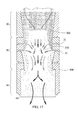
[00172]図17は、ガス化装置の切欠き側面図であり、矢印がガス化工程を描いている。3つのタイプの酸化剤ストリームが、すなわちパージ酸化剤ストリーム、ベッド酸化剤ストリームおよびピアノ酸化剤ストリームが3つの別個の対応する入口地点を介してガス化装置に進入する。パージ酸化剤ストリームは供給原料に対して投入され、圧力ロックを介して供給原料と共にガス化装置に進入する酸化剤ストリームである。パージ酸化剤ストリームはまた、圧力ロックへの逆流からの停滞ガスを阻止する。ベッド酸化剤ストリームは、ガス化装置の頂部に配置された入口11を介してガス化装置に進入する。平面酸化剤ストリームは、酸化区域30の周辺部の周りでリング内に配置された平面空気入口31、32を介してガス化装置に進入する。制御システムが、このような酸化剤ストリームの各々を監視し調節することで、ガス化装置の各々の区域における酸素の総量および生成される発生炉ガスの量を管理する。制御システムは、異なる水分含有量、かさ密度を有する供給原料に合うように調節するために、あるいはさらには供給原料のBTU値が変化することが理由でこのような酸化剤ストリームの体積および速度を調節することができる。制御システムによって、ガス化装置が作動される間に変更を行なうことが可能になり、その結果、ガス化装置を停止させるまたは再構成する必要がない。
[00172] FIG. 17 is a cutaway side view of the gasifier with arrows depicting the gasification process. Three types of oxidant streams, namely purge oxidant stream, bed oxidant stream and piano oxidant stream, enter the gasifier through three separate corresponding entry points. The purge oxidant stream is the oxidant stream that is charged to the feed and enters the gasifier with the feed via a pressure lock. The purge oxidant stream also prevents stagnant gas from backflow to the pressure lock. The bed oxidant stream enters the gasifier through an
[00173]ガス化装置に供給される酸素が多くなると、より迅速に供給原料が酸化区域においてガス化される。反応を早めると、より多くのバイオ炭が生成され、還元区域40内に蓄積される。
[00173] The more oxygen supplied to the gasifier, the faster the feedstock is gasified in the oxidation zone. As the reaction is accelerated, more biochar is produced and accumulated in the
[00174]ガス化装置における火格子50および酸化剤ストリームの変量制御を目的とした制御システムの実装は、発生炉ガスの濃度および品質も保証する。
[00174] Implementation of a control system aimed at variable control of the
[00175]熱電対およびセラミックライニング
[00176]ガス化装置では複数の異なる重複する制御方法が使用されており、ほとんどが、工程全体を通してより正確な制御を実現することができる手段として機能する。一実施形態において、効果的な制御方法は、各々の区域の温度によって示される熱勾配または熱プロフィールを監視することである。このような温度は、ガス化装置のライニングされた壁の内側に埋め込まれた熱電対によって得られる。この温度勾配または熱プロフィールは、各々の区域がある場所および各々の区域がガス化装置内で移動する先の極めて優れた指標である。一実施形態において、制御システムはこの情報を利用して、任意の所与の区域における酸化剤ストリームの均衡を変える、あるいは火格子50の回転およびバイパスを介して還元区域40におけるバイオ炭のベッドの高さを物理的に変えることで、各々の区域をそれより上に維持するおよび/または持続させるのを助ける。
[00175] Thermocouple and ceramic lining
[00176] A plurality of different overlapping control methods are used in the gasifier, and most function as a means by which more accurate control can be achieved throughout the process. In one embodiment, an effective control method is to monitor the thermal gradient or thermal profile indicated by the temperature of each zone. Such a temperature is obtained by a thermocouple embedded inside the lined wall of the gasifier. This temperature gradient or thermal profile is a very good indication of where each zone is and where each zone moves within the gasifier. In one embodiment, the control system uses this information to change the balance of the oxidant stream in any given zone, or to change the biochar bed in the
[00177]ある実施形態は、炭化ケイ素、酸化ケイ素、酸化アルミニウム、耐熱合金、他のセラミックあるいは高温で安定性のある別の物質によってガス化装置全体をライニングすることによって発生炉ガスの濃度を改善する。このようなライニングは、酸化帯域350から出て行く熱を均等に分散させ伝導するのを助け、ガス化装置の内部で生じる反応から熱電対を保護しつつ熱電対を利用することを可能にする。
[00177] Certain embodiments improve the concentration of the generator gas by lining the entire gasifier with silicon carbide, silicon oxide, aluminum oxide, refractory alloys, other ceramics, or another material that is stable at high temperatures. To do. Such a lining helps to disperse and conduct the heat exiting the
[00178]制御システムは、全ての異なる方法を利用し、前記方法をアルゴリズムに関する制御装置に組み込むことができる。後者は、制御システム全体を通しての冗長性を可能にするだけでなく、より大きな信頼性および効率も保証する。それはさらに、発生炉ガスが一定であり、高い品質であることも保証する。 [00178] The control system can utilize all different methods and incorporate the methods into the controller for the algorithm. The latter not only allows for redundancy throughout the control system, but also ensures greater reliability and efficiency. It further ensures that the generated furnace gas is constant and of high quality.
[00179]上記に記載したガス化装置の用途および方法はまた、還元区域40の高さを管理する有効な方法も提供する。他のガス化装置における問題は、酸化帯域350がガス化装置内の1箇所に制限され、酸化帯域350を移動させることは、その工程の機能を実質的に妨害するまたはガス化装置を破壊することになることである。このガス化装置の一実施形態において、酸化帯域350を熱分解区域20内に上に移動させる、または還元区域40内に下に移動させることができ、それでもなお制御システムによって酸化剤ストリームを配置させ、一定量のバイオ炭を除去することを可能にすることによって酸化帯域を管理および/または維持することができる。これにより供給原料の高さの崩壊またはガス化装置にわたる圧力差は、酸化帯域350をつぶすリスクなしで火格子50の回転を介して管理することができる。
[00179] The gasifier applications and methods described above also provide an effective way of managing the height of the
[00180]生成されるガス
[00181]作動中、ガス化装置は、125から145btu/ft3の発熱密度を有する発生炉ガスを形成する。このような発生炉ガスの品質は、十分な酸化剤ストリームおよび好適な供給原料がガス化装置に対して利用可能である限り継続して生成される。一実施形態において、ガス化装置は、1日当たり12から120トンの供給原料を変換する。
[00180] Gas produced
[00181] During operation, the gasifier forms a generator gas having a heat generation density of 125 to 145 btu / ft3. Such generator gas quality is continuously produced as long as sufficient oxidant stream and suitable feedstock are available to the gasifier. In one embodiment, the gasifier converts 12 to 120 tons of feedstock per day.
[00182]このガス化装置は、他のガス化装置とは極めて設計が異なっており、また発生炉ガスの出力および品質、ならびに今日市場にある他の下方流ガス化装置に対して工程の全体の効率をかなり改善することが明らかである。 [00182] This gasifier is very different in design from other gasifiers, and the overall process for the output and quality of the reactor gas and other downflow gasifiers on the market today. It is clear that the efficiency of the system is considerably improved.
[00183]多面的事項
[00184]本明細書で引用される公報、特許出願、および特許を含めた全ての参考文献は、あたかも各々の参考文献が個別におよび具体的に参考により組み込まれるように指摘され、その全体が本明細書に記載されるのと同程度に参照により本明細書に組み込まれる。
[00183] Multi-faceted matters
[00184] All references, including publications, patent applications, and patents cited herein, are pointed out as if each reference was individually and specifically incorporated by reference, in its entirety. Incorporated herein by reference to the same extent as described herein.
[00185]発明を記述する文脈における用語「a」および「an」および「the」および同様の指示用語は、そうでないことが本明細書に指摘される、あるいは文脈によって明らかに矛盾しない限り、単数および複数の両方を包含するように解釈すべきである。用語「備える(comprising)」、「有する(having)」、「含む」(including)」および「包含する(containing)」は、そうでないことが指摘されなければ、開放式の用語として解釈すべきである(すなわち「含めるが、限定はしない」)。本明細書で値としての範囲の記述は、そうでないことが本明細書において指摘されなければ、この範囲内にある各々の個別の値を個々に指す簡単な方法として機能することが単に意図されているだけであり、各々の個別の値は、この値が本明細書に個別に記述されているかのように明細書に組み込まれる。本明細書に記載される全ての方法は、本明細書で指摘される、または文脈によって明らかに矛盾していなければ任意の好適な順序で行なうことができる。本明細書で提供される任意のおよび全ての実施例、または例示的な用語(例えば「など」)の利用は、単に本発明をより適切に解明することが意図されるのみであり、そうでないことが主張されなければ本発明の範囲を限定するものではない(すなわち「など、但し限定はしない」)。明細書中の用語はいずれも、本発明の実施に必須である何らかの主張されない要素を示すものと解釈すべきではない。 [00185] The terms "a" and "an" and "the" and like indicating terms in the context of describing the invention are singular unless otherwise indicated herein or otherwise clearly contradicted by context. And should be interpreted to encompass both. The terms “comprising”, “having”, “including” and “containing” should be interpreted as open terms unless otherwise indicated. Yes (ie “include but not limit”). The recitation of a range as a value herein is merely intended to serve as a simple way to individually point to each individual value within the range, unless otherwise indicated herein. Each individual value is incorporated into the specification as if it were individually described herein. All methods described herein can be performed in any suitable order unless otherwise indicated herein or otherwise clearly contradicted by context. Use of any and all examples or exemplary terms (eg “etc.”) provided herein is merely intended to better elucidate the present invention, and not Does not limit the scope of the invention (i.e., but not limited thereto). No language in the specification should be construed as indicating any non-claimed element as essential to the practice of the invention.
[00186]本発明の好ましい実施形態が、ここに記載されている。このような好ましい実施形態の変形形態は、前述の記載を読むことで当業者に明らかになるであろう。本発明者等は、熟練工がこのような変形形態を適切に採用することを予測し、本発明者等は、本発明が本明細書に具体的に記載されるとは別の方法で実施されることを意図している。したがって本発明は、適用可能な法律によって許可されたここに添付されるクレームに列記される主題の全ての修正形態および等価物を含める。さらに、この全ての可能な変形形態における上記に記載した要素の何らかの組み合わせは、本明細書にそうでないことが指摘される、あるいは文脈によって明らかに矛盾しなければ、本発明によって包含される。 [00186] Preferred embodiments of the invention are described herein. Variations of such preferred embodiments will become apparent to those skilled in the art upon reading the foregoing description. The inventors anticipate that skilled workers will appropriately employ such variations, and that the inventors have implemented the invention in a manner different from that specifically described herein. Is intended to be. Accordingly, this invention includes all modifications and equivalents of the subject matter recited in the claims appended hereto as permitted by applicable law. Moreover, any combination of the above-described elements in all possible variations thereof is encompassed by the invention unless otherwise indicated herein or otherwise clearly contradicted by context.
[00187]上記の開示は、単に例示の目的のみで提示された実施例と共に本発明の原理を記載しているが、本発明の利用は、添付される特許請求の範囲の範囲およびその均等物の範囲内で、全ての通常の変形形態、適合形態および/または修正形態を含めることを理解すべきである。当業者は、上述から、今しがた記載された実施形態の種々の適合形態および修正形態は、本発明の範囲および精神から逸脱せずに構成することができることを理解するであろう。したがって、添付される特許請求の範囲において、本発明は本明細書に具体的に記載される方法以外で実施される場合もあることを理解すべきである。 [00187] While the foregoing disclosure describes the principles of the present invention in conjunction with examples presented for purposes of illustration only, the use of the present invention is intended to fall within the scope of the appended claims and their equivalents. It should be understood that all normal variations, adaptations and / or modifications are included within the scope of. Those skilled in the art will appreciate from the foregoing that various adaptations and modifications of the embodiments just described can be made without departing from the scope and spirit of the invention. Therefore, it is to be understood that, within the scope of the appended claims, the present invention may be practiced otherwise than as specifically described herein.
Claims (49)
少なくとも3つの連続する反応区域であって、中心の収束部に向かって角度を成す熱分解区域と、その後に続く酸化区域であり、前記酸化区域に相当する前記管の中央の部分が広げられた酸化区域と、その後に続く還元区域であり、前記還元区域に相当する管の内壁が、前記酸化区域に相当する管より大きな直径を有する還元区域とを含む、少なくとも3つの連続する反応区域と、
空気を噴射するために前記酸化区域内に配置された平面空気入口の少なくとも2つのリングと、
前記還元区域の下に配置されているが前記還元区域に接触はしていない、回転式で垂直方向に調節可能な火格子と
を備え、
供給原料のガス化のために使用される部分開放コア型の下方流ガス化装置である、ガス化装置。 A plurality of coupled vertically disposed tubes having an inner wall, an outer wall, a proximal end providing an inlet, and a distal end providing an outlet;
At least three successive reaction zones, a pyrolysis zone that is angled towards the central convergence, followed by an oxidation zone, with the central portion of the tube corresponding to the oxidation zone widened At least three successive reaction zones comprising an oxidation zone and a subsequent reduction zone, wherein the inner wall of the tube corresponding to said reduction zone has a reduction zone having a larger diameter than the tube corresponding to said oxidation zone;
At least two rings of planar air inlets arranged in the oxidation zone for injecting air;
A rotary and vertically adjustable grate disposed below the reduction zone but not in contact with the reduction zone;
A gasifier, which is a partially open core downflow gasifier used for feedstock gasification.
前記供給原料に着火して酸化帯域を形成するステップと、
平面空気入口の少なくとも2つのリングを利用して前記酸化区域に酸化剤ストリームを噴射するステップと、
前記供給原料が流動化し分解し始める熱分解区域、前記供給原料が発生炉ガスへ変化する酸化区域、および前記発生炉ガスがバイオ炭と混ざり合って冷却し追加の発生炉ガスを形成する還元区域を順番に通るように供給原料を移動させるステップと、
前記還元区域の下に配置された回転式の垂直方向に調節可能な火格子を利用して前記ガス化装置の内部に供給原料およびバイオ炭のベッドを保持するステップと、
バイパスおよび前記火格子内の穴を介してバイオ炭および発生炉ガスを取り除くステップと、
前記ガス化装置を供給原料で再度満たすステップと
を含む、供給原料をガス化する方法。 Filling a gasifier with a feedstock, wherein the gasifier comprises a plurality of tubes arranged in a vertical orientation, the plurality of tubes providing an inner wall, an outer wall, an inlet, a proximal end Having a distal end providing an outlet, a pyrolysis zone, an oxidation zone, and a reduction zone; and
Igniting the feedstock to form an oxidation zone;
Injecting an oxidant stream into the oxidation zone utilizing at least two rings of a planar air inlet;
A pyrolysis zone where the feedstock begins to fluidize and decompose, an oxidation zone where the feedstock is converted to generator gas, and a reduction zone where the generator gas mixes with biochar and cools to form additional generator gas Moving the feedstock in order to pass through,
Holding a bed of feedstock and biochar within the gasifier utilizing a rotary, vertically adjustable grate disposed under the reduction zone;
Removing biochar and generator gas through a bypass and a hole in the grate;
Refilling the gasifier with a feedstock, and gasifying the feedstock.
る、請求項27に記載の方法。 28. The method of claim 27, wherein the biochar bed is a sham seal for the distal end of the gasifier.
Applications Claiming Priority (4)
| Application Number | Priority Date | Filing Date | Title |
|---|---|---|---|
| US13/751,983 | 2013-01-28 | ||
| US13/751,983 US8721748B1 (en) | 2013-01-28 | 2013-01-28 | Device with dilated oxidation zone for gasifying feedstock |
| US13/752,021 US8546636B1 (en) | 2013-01-28 | 2013-01-28 | Method for gasifying feedstock |
| US13/752,021 | 2013-01-28 |
Related Parent Applications (1)
| Application Number | Title | Priority Date | Filing Date |
|---|---|---|---|
| JP2015555136A Division JP6179041B2 (en) | 2013-01-28 | 2013-01-29 | Device for gasifying feedstock |
Publications (2)
| Publication Number | Publication Date |
|---|---|
| JP2017186565A true JP2017186565A (en) | 2017-10-12 |
| JP6402419B2 JP6402419B2 (en) | 2018-10-10 |
Family
ID=51227929
Family Applications (2)
| Application Number | Title | Priority Date | Filing Date |
|---|---|---|---|
| JP2015555136A Expired - Fee Related JP6179041B2 (en) | 2013-01-28 | 2013-01-29 | Device for gasifying feedstock |
| JP2017096559A Expired - Fee Related JP6402419B2 (en) | 2013-01-28 | 2017-05-15 | Method and device for gasifying a feedstock |
Family Applications Before (1)
| Application Number | Title | Priority Date | Filing Date |
|---|---|---|---|
| JP2015555136A Expired - Fee Related JP6179041B2 (en) | 2013-01-28 | 2013-01-29 | Device for gasifying feedstock |
Country Status (15)
| Country | Link |
|---|---|
| EP (1) | EP2948658B1 (en) |
| JP (2) | JP6179041B2 (en) |
| CN (1) | CN105026725B (en) |
| AU (1) | AU2013375286B2 (en) |
| BR (1) | BR112015017918B1 (en) |
| CA (1) | CA2899123C (en) |
| CR (1) | CR20150415A (en) |
| DO (1) | DOP2015000179A (en) |
| ES (1) | ES2727960T3 (en) |
| IL (1) | IL240175B (en) |
| MX (1) | MX365196B (en) |
| MY (1) | MY175172A (en) |
| PH (1) | PH12015501856B1 (en) |
| SG (2) | SG11201505847QA (en) |
| WO (1) | WO2014116267A1 (en) |
Families Citing this family (13)
| Publication number | Priority date | Publication date | Assignee | Title |
|---|---|---|---|---|
| CN106345408A (en) * | 2016-09-23 | 2017-01-25 | 北京甸甸丰生物科技有限公司 | Preparation containing plant extract and deodorizer |
| JP6668283B2 (en) * | 2017-03-24 | 2020-03-18 | ヤンマー株式会社 | Gasifier |
| JP6633563B2 (en) * | 2017-03-24 | 2020-01-22 | ヤンマー株式会社 | Gasifier |
| CN107142127B (en) * | 2017-06-30 | 2023-03-31 | 商丘市恒盛机械制造有限公司 | Automatic stirring type material level control device |
| DE102017213195A1 (en) * | 2017-07-31 | 2019-01-31 | Entrade Energiesysteme Ag | Grate device for a fixed bed gasifier for producing a product gas from pourable carbonaceous feedstocks, fixed bed gasifier with such a grate device and use of such a fixed bed gasifier |
| CN108192667B (en) * | 2017-12-29 | 2020-04-10 | 扬州大学 | Biomass gasification furnace and gasification operation method thereof |
| CA3090756A1 (en) * | 2018-02-08 | 2019-08-15 | Societa' Per Azioni Curti-Costruzioni Meccaniche | Gasification plant |
| US11788021B2 (en) * | 2018-11-28 | 2023-10-17 | Kbi Invest & Management Ag | Reactor and process for gasifying and/or melting of feed materials |
| ES2934490T3 (en) * | 2018-11-28 | 2023-02-22 | African Rainbow Minerals Ltd | Reactor and process for the gasification and/or fusion of raw materials |
| JP2020105451A (en) * | 2018-12-28 | 2020-07-09 | ユア・エネルギー開発株式会社 | Gasification furnace using biomass feedstock |
| CN111826172A (en) * | 2020-06-29 | 2020-10-27 | 中冶天工集团天津有限公司 | Coke oven gas buried pipe installation method |
| CN113587103B (en) * | 2021-07-28 | 2024-06-14 | 中国铁建重工集团股份有限公司 | Pyrolysis gasification furnace |
| GB2622377A (en) * | 2022-09-13 | 2024-03-20 | Gasification Consultancy Ltd | Gasification |
Citations (5)
| Publication number | Priority date | Publication date | Assignee | Title |
|---|---|---|---|---|
| JPH01115995A (en) * | 1987-10-28 | 1989-05-09 | Edward F Mayer | Gasifying apparatus |
| JP2000505123A (en) * | 1996-03-07 | 2000-04-25 | ゼヴァル エントゾルグングザンラーゲン ゲーエムベーハー | Downstream fixed bed gasifier and its use. |
| JP2002516381A (en) * | 1998-05-28 | 2002-06-04 | デダール リミテッド | Gasifier with non-radial tuyeres |
| US20090119993A1 (en) * | 2007-07-10 | 2009-05-14 | Neves Alan M | Parallel path, downdraft gasifier apparatus and method |
| WO2010095025A2 (en) * | 2009-02-20 | 2010-08-26 | Socoges S.R.L. | High performance gasifier equipped with an improved combustion chamber and a mixing device |
Family Cites Families (11)
| Publication number | Priority date | Publication date | Assignee | Title |
|---|---|---|---|---|
| US2516141A (en) * | 1949-07-01 | 1950-07-25 | Louis L Newman | Apparatus and method for gasifying carbonaceous material |
| SE453670C (en) * | 1986-07-08 | 1989-09-25 | Waste Gas Energy Ab Wge | DEVICE FOR THE PREPARATION OF GAS FROM FIXED BRAINS |
| US5226927A (en) * | 1991-02-13 | 1993-07-13 | Southern California Edison | Wood gasifier |
| WO1994016038A1 (en) * | 1992-12-30 | 1994-07-21 | Combustion Engineering, Inc. | Circular slag tap for a gasifier |
| US6112677A (en) * | 1996-03-07 | 2000-09-05 | Sevar Entsorgungsanlagen Gmbh | Down-draft fixed bed gasifier system and use thereof |
| DK174582B1 (en) * | 2001-11-05 | 2003-06-30 | Biosynergi Proces Aps | Solid biofuel gasification process and generator |
| GB0325668D0 (en) * | 2003-11-04 | 2003-12-10 | Dogru Murat | Intensified and minaturized gasifier with multiple air injection and catalytic bed |
| CA2613427C (en) * | 2005-06-28 | 2014-04-08 | Community Power Corporation | Method and apparatus for automated, modular, biomass power generation |
| US7569204B2 (en) * | 2006-02-27 | 2009-08-04 | Zeropoint Clean Tech, Inc. | Apparatus and method for controlling the gas composition produced during the gasification of carbon containing feeds |
| JP2008081635A (en) * | 2006-09-28 | 2008-04-10 | Tsukishima Kikai Co Ltd | Method for gasifying woody biomass |
| FI2606105T3 (en) * | 2010-08-16 | 2023-01-31 | Sandwich gasification process for high-efficiency conversion of carbonaceous fuels to clean syngas with zero residual carbon discharge |
-
2013
- 2013-01-29 ES ES13873081T patent/ES2727960T3/en active Active
- 2013-01-29 MX MX2015009729A patent/MX365196B/en active IP Right Grant
- 2013-01-29 WO PCT/US2013/023606 patent/WO2014116267A1/en active Application Filing
- 2013-01-29 CA CA2899123A patent/CA2899123C/en active Active
- 2013-01-29 BR BR112015017918-5A patent/BR112015017918B1/en active IP Right Grant
- 2013-01-29 EP EP13873081.7A patent/EP2948658B1/en active Active
- 2013-01-29 MY MYPI2015001869A patent/MY175172A/en unknown
- 2013-01-29 JP JP2015555136A patent/JP6179041B2/en not_active Expired - Fee Related
- 2013-01-29 AU AU2013375286A patent/AU2013375286B2/en active Active
- 2013-01-29 CN CN201380074036.8A patent/CN105026725B/en not_active Expired - Fee Related
- 2013-01-29 SG SG11201505847QA patent/SG11201505847QA/en unknown
- 2013-01-29 SG SG10201706842YA patent/SG10201706842YA/en unknown
-
2015
- 2015-07-27 IL IL240175A patent/IL240175B/en active IP Right Grant
- 2015-07-27 DO DO2015000179A patent/DOP2015000179A/en unknown
- 2015-08-13 CR CR20150415A patent/CR20150415A/en unknown
- 2015-08-24 PH PH12015501856A patent/PH12015501856B1/en unknown
-
2017
- 2017-05-15 JP JP2017096559A patent/JP6402419B2/en not_active Expired - Fee Related
Patent Citations (5)
| Publication number | Priority date | Publication date | Assignee | Title |
|---|---|---|---|---|
| JPH01115995A (en) * | 1987-10-28 | 1989-05-09 | Edward F Mayer | Gasifying apparatus |
| JP2000505123A (en) * | 1996-03-07 | 2000-04-25 | ゼヴァル エントゾルグングザンラーゲン ゲーエムベーハー | Downstream fixed bed gasifier and its use. |
| JP2002516381A (en) * | 1998-05-28 | 2002-06-04 | デダール リミテッド | Gasifier with non-radial tuyeres |
| US20090119993A1 (en) * | 2007-07-10 | 2009-05-14 | Neves Alan M | Parallel path, downdraft gasifier apparatus and method |
| WO2010095025A2 (en) * | 2009-02-20 | 2010-08-26 | Socoges S.R.L. | High performance gasifier equipped with an improved combustion chamber and a mixing device |
Also Published As
| Publication number | Publication date |
|---|---|
| WO2014116267A1 (en) | 2014-07-31 |
| SG10201706842YA (en) | 2017-10-30 |
| CN105026725A (en) | 2015-11-04 |
| CA2899123A1 (en) | 2014-07-31 |
| JP2016508526A (en) | 2016-03-22 |
| IL240175B (en) | 2018-08-30 |
| BR112015017918B1 (en) | 2021-12-28 |
| IL240175A0 (en) | 2015-09-24 |
| EP2948658B1 (en) | 2019-05-08 |
| CR20150415A (en) | 2016-04-08 |
| JP6402419B2 (en) | 2018-10-10 |
| PH12015501856A1 (en) | 2015-12-07 |
| MX365196B (en) | 2019-05-27 |
| DOP2015000179A (en) | 2015-09-30 |
| AU2013375286B2 (en) | 2017-03-02 |
| SG11201505847QA (en) | 2015-08-28 |
| ES2727960T3 (en) | 2019-10-21 |
| EP2948658A4 (en) | 2017-02-08 |
| PH12015501856B1 (en) | 2015-12-07 |
| JP6179041B2 (en) | 2017-08-16 |
| MY175172A (en) | 2020-06-12 |
| CA2899123C (en) | 2017-08-15 |
| MX2015009729A (en) | 2015-11-13 |
| BR112015017918A2 (en) | 2017-07-11 |
| CN105026725B (en) | 2017-03-08 |
| EP2948658A1 (en) | 2015-12-02 |
| AU2013375286A1 (en) | 2015-08-13 |
Similar Documents
| Publication | Publication Date | Title |
|---|---|---|
| JP6402419B2 (en) | Method and device for gasifying a feedstock | |
| US10465133B2 (en) | Device with dilated oxidation zone for gasifying feedstock | |
| US10662386B2 (en) | Method for gasifying feedstock with high yield production of biochar | |
| US8829262B2 (en) | Method for gasifying feedstock | |
| US11566191B2 (en) | System and process for continuous production of contaminate free, size specific biochar following gasification | |
| US20100107493A1 (en) | Bulk fueled gasifiers | |
| WO2021061171A1 (en) | Method for gasifying feedstock with high yield production of biochar | |
| EP3475395A1 (en) | Pyrogasification unit and process | |
| US5318602A (en) | Fuel gas generator for lean gas generation | |
| JP6008306B2 (en) | Gasifier for solid carbon fuel and equipment for gas production and combustion | |
| WO2011057040A2 (en) | Direct-fired pressurized continuous coking | |
| US11939545B2 (en) | Inclined rotary gasifier waste to energy system | |
| OA17533A (en) | Method and device for gasifying feedstock. | |
| JP2006145124A (en) | Gasifier and operating method therefor |
Legal Events
| Date | Code | Title | Description |
|---|---|---|---|
| A521 | Request for written amendment filed |
Free format text: JAPANESE INTERMEDIATE CODE: A523 Effective date: 20170802 |
|
| A977 | Report on retrieval |
Free format text: JAPANESE INTERMEDIATE CODE: A971007 Effective date: 20180523 |
|
| A131 | Notification of reasons for refusal |
Free format text: JAPANESE INTERMEDIATE CODE: A131 Effective date: 20180529 |
|
| A521 | Request for written amendment filed |
Free format text: JAPANESE INTERMEDIATE CODE: A523 Effective date: 20180730 |
|
| TRDD | Decision of grant or rejection written | ||
| A01 | Written decision to grant a patent or to grant a registration (utility model) |
Free format text: JAPANESE INTERMEDIATE CODE: A01 Effective date: 20180814 |
|
| A61 | First payment of annual fees (during grant procedure) |
Free format text: JAPANESE INTERMEDIATE CODE: A61 Effective date: 20180823 |
|
| R150 | Certificate of patent or registration of utility model |
Ref document number: 6402419 Country of ref document: JP Free format text: JAPANESE INTERMEDIATE CODE: R150 |
|
| R250 | Receipt of annual fees |
Free format text: JAPANESE INTERMEDIATE CODE: R250 |
|
| R250 | Receipt of annual fees |
Free format text: JAPANESE INTERMEDIATE CODE: R250 |
|
| LAPS | Cancellation because of no payment of annual fees |