JP2017185458A - Cylindrical substrate coating film removing method and electrophotographic photosensitive manufacturing method - Google Patents
Cylindrical substrate coating film removing method and electrophotographic photosensitive manufacturing method Download PDFInfo
- Publication number
- JP2017185458A JP2017185458A JP2016077014A JP2016077014A JP2017185458A JP 2017185458 A JP2017185458 A JP 2017185458A JP 2016077014 A JP2016077014 A JP 2016077014A JP 2016077014 A JP2016077014 A JP 2016077014A JP 2017185458 A JP2017185458 A JP 2017185458A
- Authority
- JP
- Japan
- Prior art keywords
- coating film
- peripheral surface
- outer peripheral
- substrate
- film removing
- Prior art date
- Legal status (The legal status is an assumption and is not a legal conclusion. Google has not performed a legal analysis and makes no representation as to the accuracy of the status listed.)
- Granted
Links
Images


Landscapes
- Photoreceptors In Electrophotography (AREA)
- Application Of Or Painting With Fluid Materials (AREA)
Abstract
Description
本発明は、浸漬塗布法によって電子写真感光体用塗布液の塗膜を形成した円筒状の基体の長手方向下方の不要な塗膜を除去する方法に関する。 The present invention relates to a method for removing an unnecessary coating film below a longitudinal direction of a cylindrical substrate on which a coating film of a coating solution for an electrophotographic photoreceptor is formed by a dip coating method.
複写機、レーザービームプリンタなどに用いられる電子写真感光体は、例えば円筒状の基体上に導電層、下引き層、電荷発生層や電荷輸送層等が設けられている。このような電子写真感光体の製造方法として、基体上に電子写真感光体を構成する上記各層の塗布液(電子写真感光体用塗布液)の塗膜を形成し、これを加熱や硬化する方法がある。中でも、円筒状の基体を電子写真感光体用塗布液中に例えば基体の軸を鉛直方向にして浸漬し、その後引き上げることにより塗膜を形成する浸漬塗布法がその生産性の高さという点から広く採用されている。しかし、浸漬塗布法では基体下方外周面にも必然的に塗膜が形成される。 An electrophotographic photosensitive member used in a copying machine, a laser beam printer, or the like is provided with a conductive layer, an undercoat layer, a charge generation layer, a charge transport layer, and the like on a cylindrical substrate, for example. As a method for producing such an electrophotographic photosensitive member, a method of forming a coating film of the above-described respective layers constituting the electrophotographic photosensitive member (coating solution for an electrophotographic photosensitive member) on a substrate and heating or curing the coating film. There is. Among them, the dip coating method in which a coating film is formed by immersing a cylindrical substrate in a coating solution for an electrophotographic photosensitive member, for example, with the axis of the substrate in the vertical direction and then pulling it up is from the point of high productivity. Widely adopted. However, in the dip coating method, a coating film is inevitably formed on the lower outer peripheral surface of the substrate.
ここで、電子写真感光体と現像部材(現像スリーブなど)との間の距離を一定に保つための部材(コロ)を電子写真感光体に当接させる構成をとる場合がある。その場合、コロが当接する部分は、摺擦を受けるため、塗膜が存在すると、不均一に剥離されたり摩耗したりするという問題がある。したがって、その部分には塗膜が形成されていないことが必要である。
そこで、円筒状の基体に浸漬塗布法によって塗膜を形成する場合、塗膜形成後に基体下方外周面の不要な塗膜を除去する工程が必要である。
Here, there may be a configuration in which a member (roller) for maintaining a constant distance between the electrophotographic photosensitive member and the developing member (developing sleeve or the like) is brought into contact with the electrophotographic photosensitive member. In that case, since the portion where the roller abuts is rubbed, there is a problem that if the coating film is present, it is peeled off unevenly or worn. Therefore, it is necessary that no coating film is formed on that portion.
Therefore, when forming a coating film on a cylindrical substrate by a dip coating method, a step of removing an unnecessary coating film on the lower outer peripheral surface of the substrate after the coating film formation is necessary.
そのため、感光体下端部の塗膜を除去する装置が提案されている。例えば、特許文献1では、円筒状基体下端内部に挿入した装置から溶剤を吐出し、ブラシで摺擦することで塗布膜を除去する装置が提案されている。特許文献2では、円筒状基体外周面に基体の回転方向上流側の面に切り込みを設けたブレードで摺擦することで塗布膜を除去する装置が提案されている。また、特許文献3では、円筒状基体の内部の塗膜を除去するための、下端が溶剤槽に浸漬し上端が基体の先端に嵌入可能な円柱状の拭取り部材と、前記基体と前記拭取り部材とを相対的に回転させる回転機構とを備えた塗膜除去装置が提案されている。さらに、特許文献4では、電子写真感光体の端部の塗膜を除去し、除去する必要のない塗膜部分の劣化を抑制するために、覆い部材と感光体下端の内周壁の塗膜除去のための多孔質状の除去部材と感光体下端の外周壁の塗膜除去のための樹脂製のプレート材とを備えた塗膜除去装置が提案されている。
Therefore, an apparatus for removing the coating film on the lower end of the photoreceptor has been proposed. For example, Patent Document 1 proposes an apparatus for removing a coating film by discharging a solvent from an apparatus inserted into the lower end of a cylindrical substrate and rubbing with a brush.
塗膜を基体上から精度よく除去するには、溶剤の存在下に除去部材で塗膜を摺擦することにより、溶剤で塗膜を溶解しながら洗い流す必要があり、溶剤の供給量が重要である。しかしながら、特許文献1や特許文献2に記載された除去部材では溶剤の供給量が十分でなく、塗膜除去の精度が悪くなる課題があった。また、特許文献3に記載された塗膜除去装置では、回転により溶剤が供給される反面、拭取り部材のみを回転させた場合には、速い回転により溶剤が飛び散るため、基体と拭取り部材とを相対的に回転させる機構が必須となる。さらに、特許文献3に記載された塗膜除去装置において、拭取り部材は周面全体を覆うように接する必要があるため、外周面の塗膜を除去する際には、基体上の塗膜と塗膜を剥離する部分との境界に溶剤が貯留し、塗膜端部が不均一となってしまうという課題を有する。またさらに、特許文献4に記載された塗膜除去装置においては、除去する必要のない塗膜部分の劣化を抑制することはできるものの、塗膜除去部への溶媒の供給量が十分でなく、十分な塗膜の除去の精度という点では依然として課題を有している。
In order to remove the coating film from the substrate with high accuracy, it is necessary to wash away the coating film while dissolving the coating film with the solvent by rubbing the coating film with the removing member in the presence of the solvent, and the supply amount of the solvent is important. is there. However, the removal members described in Patent Document 1 and
本発明の目的は、浸漬塗布法による電子写真感光体用塗布液の塗膜が形成された円筒状の基体下方の外周面の不要な塗膜を、精度よく効率的に塗膜を除去することが可能な円筒状の基体の塗膜除去方法および電子写真感光体の製造方法を提供することである。 An object of the present invention is to accurately and efficiently remove an unnecessary coating film on an outer peripheral surface below a cylindrical substrate on which a coating film of a coating solution for an electrophotographic photoreceptor is formed by a dip coating method. It is an object of the present invention to provide a method for removing a coating film on a cylindrical substrate and a method for producing an electrophotographic photoreceptor.
本発明は、電子写真感光体用塗布液の塗膜が形成された円筒状の基体を鉛直方向に支持し、該基体の外周面の長手方向下方にある被除去部の塗膜を、少なくとも上端部が開放された溝形状を有する外周面塗膜除去部材を用いて除去する塗膜除去方法であって、
該方法が、
該基体の外周面の該被除去部に該外周面塗膜除去部材の該溝形状を有する面を該基体に対向させ、該溝形状と該基体とで空間を形成するように当接する工程、
溶剤が、該空間の下端よりしみ上がることで、該空間に該溶剤を供給する工程、および
該基体と該外周面塗膜除去部材とを相対的に回転させて摺擦し、該被除去部の塗膜を除去する工程、を有することを特徴とする円筒状の基体の塗膜除去方法である。
The present invention supports a cylindrical substrate on which a coating film of a coating solution for an electrophotographic photosensitive member is formed in the vertical direction, and has a coating film on a portion to be removed at the lower end in the longitudinal direction of the outer peripheral surface of the substrate. It is a coating film removing method for removing using an outer peripheral surface coating film removing member having a groove shape with an open part,
The method is
A step of contacting the surface of the outer peripheral surface coating film removing member having the groove shape with the portion to be removed of the outer peripheral surface of the base body so as to be opposed to the base body so as to form a space between the groove shape and the base body;
The solvent oozes from the lower end of the space, the step of supplying the solvent to the space, and the base and the outer peripheral surface coating film removing member are relatively rubbed and rubbed, and the portion to be removed And a step of removing the coating film. The method of removing a coating film on a cylindrical substrate, comprising:
また、本発明は、円筒状の基体に浸漬塗布法により電子写真感光体用塗布液の塗膜を形成する電子写真感光体の製造方法において、
浸漬塗布法により該基体に電子写真感光体用塗布液の塗膜を形成後、上記の塗膜除去方法により該基体の長手方向下方にある塗膜を除去する工程を有する電子写真感光体の製造方法である。
Further, the present invention provides a method for producing an electrophotographic photosensitive member, wherein a coating film of a coating solution for an electrophotographic photosensitive member is formed on a cylindrical substrate by a dip coating method.
Production of an electrophotographic photosensitive member having a step of forming a coating film of a coating solution for an electrophotographic photosensitive member on the substrate by a dip coating method, and then removing a coating film below the longitudinal direction of the substrate by the coating film removing method. Is the method.
本発明によれば、浸漬塗布法による電子写真感光体用塗布液の塗膜が形成された円筒状の基体下方の外周面の不要な塗膜を、精度よく効率的に塗膜を除去することが可能になる。また、該塗膜除去方法を用いて電子写真感光体を製造することにより、基体の不要な領域に塗膜の層が設けられていない電子写真感光体を得ることが可能になる。 According to the present invention, an unnecessary coating film on an outer peripheral surface under a cylindrical substrate on which a coating film of a coating solution for an electrophotographic photoreceptor is formed by a dip coating method can be efficiently and efficiently removed. Is possible. Further, by producing an electrophotographic photosensitive member using the coating film removing method, it is possible to obtain an electrophotographic photosensitive member in which a coating layer is not provided in an unnecessary region of the substrate.
本発明は、電子写真感光体用塗布液の塗膜が形成された円筒状の基体を鉛直方向に支持し、該基体の外周面の長手方向下方にある被除去部の塗膜を、少なくとも上端部が開放された溝形状を有する外周面塗膜除去部材を用いて除去する塗膜除去方法であって、
該方法が、
該基体の外周面の該被除去部に該外周面塗膜除去部材の該溝形状を有する面を該基体に対向させ、該溝形状と該基体とで空間を形成するように当接する工程
溶剤が、該空間の下端よりしみ上がることで、該空間に該溶剤を供給する工程、および
該基体と該外周面塗膜除去部材とを相対的に回転させて摺擦し、該被除去部の塗膜を除去する工程、を有することを特徴とする円筒状の基体の塗膜除去方法である。
The present invention supports a cylindrical substrate on which a coating film of a coating solution for an electrophotographic photosensitive member is formed in the vertical direction, and has a coating film on a portion to be removed at the lower end in the longitudinal direction of the outer peripheral surface of the substrate. It is a coating film removing method for removing using an outer peripheral surface coating film removing member having a groove shape with an open part,
The method is
A step of contacting the surface of the outer peripheral surface coating film removing member having the groove shape with the portion to be removed of the outer peripheral surface of the substrate, and contacting the substrate to form a space between the groove shape and the substrate However, when the solvent oozes up from the lower end of the space, the solvent is supplied to the space, and the base and the outer peripheral surface coating film removing member are relatively rotated and rubbed to remove the part to be removed. And a step of removing the coating film. A method of removing a coating film from a cylindrical substrate.
また、本発明は、円筒状の基体に浸漬塗布法により電子写真感光体用塗布液の塗膜を形成する電子写真感光体の製造方法において、
浸漬塗布法により該基体に電子写真感光体用塗布液の塗膜を形成後、上記の円筒状の基体の塗膜除去方法により該基体の長手方向下方にある塗膜を除去する工程を有する電子写真感光体の製造方法である。
Further, the present invention provides a method for producing an electrophotographic photosensitive member, wherein a coating film of a coating solution for an electrophotographic photosensitive member is formed on a cylindrical substrate by a dip coating method.
An electron having a step of forming a coating film of a coating solution for an electrophotographic photosensitive member on the substrate by a dip coating method and then removing a coating film below the longitudinal direction of the substrate by a coating film removing method for the cylindrical substrate. This is a method for producing a photographic photoreceptor.
以下本発明について、図面を用いて詳細に説明する。
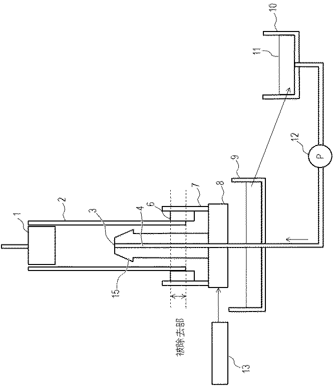
本発明の塗膜除去方法に用いられる塗膜除去装置について図1を例にして説明する。図1は、本発明の塗膜除去方法に用いられる塗膜除去装置の全体の概略構成を示す断面図である。
Hereinafter, the present invention will be described in detail with reference to the drawings.
A coating film removing apparatus used in the coating film removing method of the present invention will be described with reference to FIG. FIG. 1 is a cross-sectional view showing an overall schematic configuration of a coating film removing apparatus used in the coating film removing method of the present invention.
図1に示すように、本発明の塗膜除去方法に用いられる塗膜除去装置は、塗膜が形成された円筒状の基体2を鉛直方向に支持する基体保持部材1を備えている。また該塗膜除去装置は、基体保持部材1によって支持された基体2の長手方向下方の外周面に形成された塗膜を除去する塗膜除去機構を備えている。
As shown in FIG. 1, the coating film removing apparatus used in the coating film removing method of the present invention includes a substrate holding member 1 that supports a
塗膜除去機構は支持体8を有し、支持体8は、基体2内に挿入可能に垂直に立設された軸部15と、外周面塗膜除去部材6を保持する外周面塗膜除去部材用保持部材7を有している。回転モーター13により支持体8を回転させることで、軸部15の軸線回りに軸部15と外周面塗膜除去部材用保持部材7とを一体に回転可能となっている。
The coating film removing mechanism has a support 8, and the support 8 is an outer peripheral surface coating film removing member that holds a
軸部15は、内部に軸部15を貫通する溶剤供給流路4を有し、上端部には溶剤11が吐出される開口である溶剤供給口3を有している。溶剤11は溶剤供給タンク10より溶剤供給ポンプ12によって支持体8へ送られ、軸部15の内部に設けられた溶剤供給流路4を通って溶剤供給口3から吐出される。このとき、溶剤供給口3(すなわち軸部15の上端)は、基体2および外周面塗膜除去部材6が当接する部位の下端部(すなわち基体2および外周面塗膜除去部材6の溝形状からなる空間の下端部)よりも上方に位置している。
The
外周面塗膜除去部材用保持部材7に取り付けられた外周面塗膜除去部材6は、溝形状を有した面が基体2の外周面に当接される。溶剤供給工程において、基体2および外周面塗膜除去部材6の溝形状からなる空間の下端部に、溶剤供給口3から吐出された溶剤11が達すると、基体2の外周面に外周面塗膜除去部材6を当接することにより基体2と外周面塗膜除去部材6の溝形状との間に生じた空間に、毛細管現象により溶剤11がしみ上がることにより供給される。その後、基体2の外周面に外周面塗膜除去部材6が当接した状態で、支持体8を回転させることで、外周面塗膜除去部材6が基体2の外周面を摺擦して、被除去部の塗膜を該溶剤11により溶解しながら除去する。
The outer peripheral surface coating
また、溶剤供給口3から吐出された溶剤11を回収する溶剤回収タンク9が設けられ、溶剤回収タンク9で回収された使用済みの溶剤11は、必要に応じて精製等された後、溶剤供給タンク10に送られて、再利用される構成になっていてもよい。
Further, a
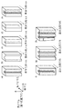
外周面塗膜除去部材6の詳細な形状を、図2を用いて説明する。
図2には、塗膜除去に用いられる外周面塗膜除去部材6の形状の斜視図を示す。本発明の外周面塗膜除去部材6は、溝形状を有している。溝形状の幅としては、図2(c)のような線状の切り込み形状、図2(a)のような矩形、図2(b)のようなU字型等が挙げられる。また、複数の溝形状を有していても良く、図2(g)のような矩形の溝が2つあるもの、図2(e)のような矩形と線状の切り込みが同時にあるものでもよい。好ましくは、図2(g)のようにそれぞれ独立した溝形状を複数有するものが好ましい。また、図2(a)のように当接させる基体2の鉛直方向に沿って、上から下まで溝形状がつながっていることが好ましい。ただし、図2(f)のように溝形状が途切れているものであっても、少なくとも上端部が開放された溝形状であれば、基体2の下端と溝との接触部に溶剤11が接することにより、該溶剤11は溝形状と基体2により形成された空間にしみ上がることにより供給されるため、本発明の外周面塗膜除去部材6として用いることができる。さらに、図2(d)のように複数の部材を重ね合わせることで、溝形状を設けることで、本発明の外周面塗膜除去部材6としても良い。
The detailed shape of the outer peripheral surface coating
In FIG. 2, the perspective view of the shape of the outer peripheral surface coating-
外周面塗膜除去部材6の溝形状の大きさは基体2と当接した状態で、基体2と外周面塗膜除去部材6の溝形状との間に生じた空間の下端部に溶剤11が接した場合に、溶剤11が上記空間内に溜められるような大きさが良い。空間の断面積が大きすぎると、溶剤11が空間の上端までしみ上がらなくなり、溶剤11を十分に供給することができなくなる。好ましい外周面塗膜除去部材6の溝形状の大きさは、外周面塗膜除去部材6の表面と溶剤11との接触角、基体2又は基体2上の塗膜等と溶剤11との接触角、溶剤11の密度等を考慮して決定することができる。好ましくは、幅寸法が0.3mm以上2.0mm以下、奥行き寸法が0.3mm以上3.0mm以下であることが好ましい。より好ましくは幅寸法が0.3mm以上1.0mm以下、奥行き寸法が0.5mm以上2.0mm以下であることが好ましい。外周面塗膜除去部材6の溝形状が前記寸法である場合、溶剤11は20mmの高さまでしみ上がることができる。
The size of the groove shape of the outer peripheral surface coating
外周面塗膜除去部材6と基体2との当接の位置関係を、図3、図4を用いて説明する。図3は図2(a)で表わされる外周面塗膜除去部材6を基体2に当接させたときの上面図である。本発明の塗膜除去方法では、図3のように、上記外周面塗膜除去部材6の溝形状を有する面を基体2に対向させて、溝形状と基体2とで空間を形成するように当接させる。そうすると、基体2と外周面塗膜除去部材6の溝形状との間に生じた空間の下端部に達した溶剤11がこの空間にしみ上がり、空間に溶剤11を溜めたまま摺擦することで、効率的な除去が可能となる。図4(a)、図4(b)のように当接させた場合は、溝形状と基体2とで空間を形成できないため、本発明の効果が得られず、効率的な塗膜除去ができない。
The positional relationship of contact between the outer peripheral surface coating
また、図2(g)のように複数の溝形状を有する外周面塗膜除去部材6と基体2との当接の位置関係を、図5を用いて説明する。図5は図2(g)で表わされる外周面塗膜除去部材6を基体2に当接させたときの上面図である。本発明の塗膜除去方法では、図5のように、外周面塗膜除去部材6が複数の溝形状を有する場合は、少なくとも1つの溝形状が、溝形状と基体2とで空間を形成できるように基体2に当接させればよい。好ましくは、図5(b)、図5(c)のように、一方の側面に適度な開口があると好ましい。開口があると、塗膜除去の際、基体2と外周面塗膜除去部材6の溝形状との間に生じた空間から染み出した溶剤11が該開口より排出され、新しい溶剤11が基体2と外周面塗膜除去部材6の溝形状との間に生じた空間にしみ上がる。このように、溶剤11がリフレッシュされることにより、除去がより効率的になる。開口は、図5(b)、図5(c)のようにして外周面塗膜除去部材6と基体2との当接の位置関係を調節することで開口を設けてもよいし、図2(h)のように外周面塗膜除去部材6の側面部の一部を凹まして開口を設けても良い。開口を設ける側面は、図5(b)のように外周面塗膜除去部材6の回転方向の上流方向側(すなわち部材の回転方向に対して反対側)の側面に設けるのがより好ましい。また、開口は、溶剤11が上記空間内にある程度溜められるような大きさが良い。開口が大きすぎて前記空間内に全く溶剤11が溜まらない場合は、溶剤11をリフレッシュさせる効果が得られない。
Moreover, the positional relationship of contact | abutting with the outer peripheral surface coating-
図1の塗膜除去装置では外周面塗膜除去部材6に供給される溶剤11は基体2の内面を伝わって供給される。図1の塗膜除去装置においては、基体2下方の内周面にも塗膜が形成されていることから、基体2の内周面の塗膜が、基体2の内部に供給される溶剤11により溶解され得る。そして、該塗膜が溶解した溶剤11が外周面に供給されることになる。そのため、内周面塗膜除去部材5を設けることにより、精度よく短時間で基体2の内面の塗膜を除去することができ、かつ、外周面の塗膜の除去精度が良好になる。
In the coating film removing apparatus of FIG. 1, the solvent 11 supplied to the outer peripheral surface coating
内周面塗膜除去部材5を設けた場合の例を図6を用いて説明する。図6は、本発明の塗膜除去方法に用いられる塗膜除去装置の除去部の近傍の概略構成を示す断面図(図6(a))および上面図(図6(b))である。図6において、図1と同一部材には同じ符号を付し、これらの構成は図1と同様であり、その説明は省略する。
An example in which the inner peripheral surface coating
図6に示す塗膜除去装置は、2つの内周面塗膜除去部材5を有する。内周面塗膜除去部材5は軸部15の側面に取り付けられており、軸部15と一緒に回転可能となっている。内周面塗膜除去部材5は、軸部15を基体2に挿入した時に、基体2の内周面に接触するように構成されており、支持体8および軸部15を回転させることで基体2の内面を摺擦して、基体2の内周面に存在している不要な塗膜を除去する機能を果たす。したがって、内周面塗膜除去部材5を有する図6に示す塗膜除去装置を用いることで、基体2の内周面の被除去部の塗膜に内周面塗膜除去部材5を当接すること(内周面塗膜除去部材当接工程)が行われる。また、基体2の内周面の被除去部の塗膜に内周面塗膜除去部材5を当接させたまま、基体2と内周面塗膜除去部材5とを相対的に回転させて摺擦し、内周面の被除去部の塗膜の除去(内周面塗膜除去工程)も行うことができる。なお、図6においては、外周面塗膜除去部材6を保持する外周面塗膜除去部材用保持部材7を有する支持体8に設けられた軸部15に内周面塗膜除去部材5が取り付けられているため、内周面塗膜除去工程は、外周面塗膜除去工程と同時に行われることになる。
The coating film removing apparatus shown in FIG. 6 has two inner peripheral surface coating
内周面塗膜除去部材5を設ける場合は、図6(b)に示すように、内周面塗膜除去部材5は、外周面塗膜除去部材6と基体2との当接部と溶剤供給口3とを結ぶ直線上を避ける位置に配置されることが好ましい。内周面塗膜除去部材5が、溶剤供給口3と外周面塗膜除去部材6と基体2との当接部とを結ぶ直線上に配置される場合、図6(b)に示す位置関係である場合と比べて、外周面塗膜除去部材6の溝形状と基体2との間に生じた空間に供給される溶剤11の量が減る。そのため、内周面塗膜除去部材5は、溶剤供給口3と外周面塗膜除去部材6と基体2との当接部とを結ぶ直線上を避ける位置に配置されることが好ましい。
When the inner peripheral surface coating
本発明の塗膜除去方法の一例について、一連の工程を図1の塗膜除去装置を用いて説明する。
まず、浸漬塗布法により外周面に塗膜が形成された円筒状の基体2を、基体保持部材1によって鉛直方向に保持する。
次に、塗膜除去を実施する領域(「被除去部」とも記載する。)の上端が外周面塗膜除去部材6の上端と同じ高さになる位置まで基体2を下降し、軸部15を挿入する。このとき基体2の外周面の被除去部の塗膜の上端から下端まで、外周面塗膜除去部材6の溝形状と基体2とで空間を形成するように当接する(外周面塗膜除去部材当接工程)。
An example of the coating film removing method of the present invention will be described with reference to a series of steps using the coating film removing apparatus shown in FIG.
First, the
Next, the
また、溶剤供給ポンプ12を作動させ溶剤供給口3から溶剤11を吐出させることにより、円筒状の基体2の内部に溶剤11を吐出する。前記吐出された溶剤11は、基体2および外周面塗膜除去部材6の溝形状からなる空間の下端部に達することで前記空間にしみ上がり、前記空間に溶剤11が供給される。(溶剤供給工程)。
Further, the solvent 11 is discharged into the
そして、この状態で溶剤11を吐出させながら回転モーター13により支持体8を回転させることで、当接させた外周面塗膜除去部材6を回転させ、不要な塗膜を摺擦し、除去を実施する(外周面塗膜除去工程)。所定の時間回転させた後、基体2を引き上げて、一連の塗膜除去工程が終了する。
In this state, the support 8 is rotated by the
前記外周面塗膜除去部材当接工程において、塗膜除去を行う位置まで基体2を下降する場合、基体2の外周面に外周面塗膜除去部材6が接触しないように外周面塗膜除去部材6を外側方向に移動させて退避させることが好ましい。そのため、外周面塗膜除去部材用保持部材7は、図示していない動作機構により基体2の半径方向の外側方向に外周面塗膜除去部材6が接触しない位置まで移動可能であることが好ましい。
In the outer peripheral surface coating film removing member abutting step, when the
詳細な動作としては、基体2を下降して移動している間は、基体2外周面に外周面塗膜除去部材6が接触しないように、外周面塗膜除去部材用保持部材7を基体2の半径方向の外側方向に移動させて退避させる。次に、所定の位置まで基体2を下降し、移動を停止した後、外周面塗膜除去部材用保持部材7を基体2の半径方向の内側方向に移動し、外周面塗膜除去部材6を基体2の外周面に当接させ、支持体8を回転させて塗膜除去を行う。外周面塗膜除去部材用保持部材7を基体2の半径方向の外側方向に移動させずに基体2を下降させると、基体2が外周面塗膜除去部材6の上端部分に接触し押圧するため、外周面塗膜除去部材6の摩耗や変形が起こりやすくなり、塗膜を除去する境界が乱れやすくなる。
As a detailed operation, the outer peripheral surface coating film removing
また、外周面塗膜除去部材6の基体2への当接の位置としては、溶剤11が外周面塗膜除去部材6と基体2で形成された空間をしみ上がり、塗膜除去を効率的に行うために、外周面塗膜除去部材6の下端が基体2の下端とほぼ同じか、又は、より下方に位置している必要がある。ただし、外周面塗膜除去部材6の下端が基体2下端よりわずかに上方に位置していても、溶剤11が基体2外周面に回り込んでしみ上がることができればよい。外周面塗膜除去部材6の下端が基体2の下端より下方に位置している方が、溶剤11が当接部をしみ上がりやすく塗膜除去が効率的になるので好ましい。
Further, as the position of contact of the outer peripheral surface coating
前記溶剤供給工程で溶剤11は基体2の内部に吐出される。この溶剤11は、軸部15の上部に位置する、下方に向かって漸次径が大きくなるテーパ面を経由して基体2の内周面に伝わる。そして、基体2の内周面を流れ落ちて基体2の下端部に達し、基体2と外周面塗膜除去部材6の溝形状との間に生じた空間の下端部から該空間にしみ上がることで、基体2の外周面の被除去部に供給される。
In the solvent supply step, the solvent 11 is discharged into the
なお、前記外周面塗膜除去工程において被除去部を外周面塗膜除去部材6により摺擦しているときに、溶剤供給口3は溶剤11を常に吐出しても良いし断続的に吐出しても良い。また、基体2を所定位置に移動するために上下動させている時など外周面塗膜除去工程の前や後に、吐出していても良い。また、溶剤11の供給方法としては、上記のような方法の他に、溶剤11中に基体2の下端部や外周面塗膜除去部材6を浸漬して供給する方法や、ノズルなどで直接外周面塗膜除去部材6と基体2との当接部に溶剤11が供給されるように供給する方法などが挙げられる。
When the portion to be removed is rubbed with the outer peripheral surface coating
溶剤11中に基体2の下端部や外周面塗膜除去部材6を浸漬して供給する具体例を、図7を用いて説明する。図7は、本発明の塗膜除去方法に用いられる塗膜除去装置の除去部の近傍の概略構成を示す断面図(図7(a))および上面図(図7(b))である。図1と同一部材には同じ符号を付し、これらの構成は図1と同様であり、その説明は省略する。
A specific example in which the lower end portion of the
図7に示す塗膜除去装置は、溶剤供給タンク10から溶剤供給ポンプ12によって送られ、溶剤供給口3から吐出された溶剤11が、一時的に貯留される溶剤貯留部16を有する。外周面塗膜除去部材用保持部材7に取り付けられた外周面塗膜除去部材6の溝形状を有した面が外周面に当接した基体2は、基体2および外周面塗膜除去部材6の溝形状からなる空間の下端部が、溶剤貯留部16中に貯留された溶剤11の液面に接するように配置され、基体2および外周面塗膜除去部材6の溝形状からなる空間を形成する。溶剤11は、毛細管現象により、基体2および外周面塗膜除去部材6の溝形状からなる該空間にしみ上がることにより供給される。その後、基体2の外周面に外周面塗膜除去部材6が当接した状態で、支持体8を回転させることで、外周面塗膜除去部材6が基体2の外周面を摺擦して除去する。外周面塗膜除去工程において被除去部を外周面塗膜除去部材6により摺擦しているときに、溶剤供給口3は溶剤11を常に吐出しても良いし断続的に吐出しても良い。溶剤11の吐出により、溶剤貯留部16中からオーバーフローした溶剤11は溶剤回収タンク9で回収される。溶剤11をオーバーフローさせることにより、溶剤貯留部16中の溶剤11の液面の高さを一定にすることができ、常に安定して基体2および外周面塗膜除去部材6の溝形状からなる空間の下端部を溶剤11に浸漬することが可能となる。
The coating film removing apparatus shown in FIG. 7 has a
本発明の塗膜除去方法で使用する溶剤11としては、特に限定されないが、塗膜を溶解又は膨潤しうるものが望ましい。 Although it does not specifically limit as the solvent 11 used with the coating-film removal method of this invention, The thing which can melt | dissolve or swell a coating film is desirable.
外周面塗膜除去部材6の材質は、耐摩耗性および耐溶剤性を考慮して選択でき、ポリエチレン、ポリエステル、ポリプロピレン、ポリイミド等の樹脂、エチレンプロピレンゴム、エチレンプロピレンジエンゴム、ブチルゴム、フッ素系ゴム等のゴムを使用することができる。
The material of the outer peripheral surface coating
外周面塗膜除去部材6の形状としては、当接部へ溶剤11がしみ上がりやすい溝形状を形成できること、連続使用時に汚れが外周面塗膜除去部材6に溜まりにくいこと、塗膜を除去する面と除去しない面の境界が乱れにくいなどの点からブレード状のものが好ましい。
As the shape of the outer peripheral surface coating
内周面塗膜除去部材5の材質は、耐摩耗性および耐溶剤性を考慮して選択できる。上記外周面塗膜除去部材6と同様に、ポリエチレン、ポリエステル、ポリプロピレン、ポリイミド等の樹脂、エチレンプロピレンゴム、エチレンプロピレンジエンゴム、ブチルゴム、フッ素系ゴム等のゴムを使用することができる。
The material of the inner peripheral surface coating
内周面塗膜除去部材5の形状は、ブレード状、ブラシ状、不織布などの布状体など特に限定されず適宜選択可能である。連続使用時に汚れが内周面塗膜除去部材5に溜まりにくいことなどの点からブレード状のものが好ましい。
The shape of the inner peripheral surface coating
図1、図6および図7において外周面塗膜除去部材6は、2つ設けられているが、1つ又は3つ以上設けられていても良い。また、図6において、内周面塗膜除去部材5は2つ設けられているが、1つ又は3つ以上設けられても良い。
1, 6, and 7, two outer peripheral surface coating
回転モーター13により支持体8を回転する速度は、適宜設定することができる。回転速度が速いほど除去にかかる時間が短く済むが、あまりに早すぎると塗膜除去部材に負荷がかかりすぎて、塗膜除去部材が変形し破損するおそれがある。
The speed at which the support 8 is rotated by the
基体2上に浸漬塗布法を用いて複数の層が形成される場合には、本発明の塗膜除去方法は、必要に応じて、基体2上に形成される各層のうち一部の層についてのみ実施してもよいし、全部の層について実施してもよい。また、複数の層について本発明の塗膜除去方法を行う場合は、各層の塗膜を形成するたびに塗膜を除去してもよいし、いくつかの乾燥塗膜を順次形成した後、一度に塗膜を除去してもよい。
When a plurality of layers are formed on the
次に、上記塗膜除去方法を用いた本発明の電子写真感光体の製造方法について、説明する。
本発明の電子写真感光体の製造方法で製造される電子写真感光体は、円筒状の基体、および基体上に形成された電荷発生物質および電荷輸送物質を含有する感光層を有する。感光層は、基体側から電荷発生物質を含有する電荷発生層と電荷輸送物質を含有する電荷輸送層をこの順に積層してなるものでも、電荷発生物質と電荷輸送物質を同一の層に含有させてなるものでもよい。基体上に感光層を直接設けると、感光層の剥がれが生じたり、基体の表面の欠陥(傷などの形状的欠陥又は不純物などの材質的欠陥)が画像にそのまま反映され、黒点状や白抜け状の画像欠陥が生じたりする場合がある。これらの問題を解消するために、下引き層を感光層と基体との間に有することが好ましい。
Next, a method for producing the electrophotographic photosensitive member of the present invention using the coating film removing method will be described.
The electrophotographic photoreceptor produced by the method for producing an electrophotographic photoreceptor of the present invention has a cylindrical substrate, and a photosensitive layer containing a charge generating material and a charge transport material formed on the substrate. Even if the photosensitive layer is formed by laminating a charge generation layer containing a charge generation material and a charge transport layer containing a charge transport material in this order from the substrate side, the charge generation material and the charge transport material are contained in the same layer. It may be. If the photosensitive layer is directly provided on the substrate, the photosensitive layer may be peeled off, or defects on the surface of the substrate (such as defects such as scratches or material defects such as impurities) will be directly reflected in the image, resulting in black spots or white spots. Image defects may occur. In order to solve these problems, it is preferable to have an undercoat layer between the photosensitive layer and the substrate.
〔円筒状の基体〕
円筒状の基体としては、導電性を有するもの(導電性基体)が好ましく、例えば、アルミニウム、ニッケル、銅、金、鉄などの金属又は合金製の基体を用いることができる。ポリエステル樹脂、ポリカーボネート樹脂、ポリイミド樹脂、ガラスなどの絶縁性基体上にアルミニウム、銀、金などの金属の薄膜を形成した基体、又は酸化インジウム、酸化スズなどの導電性材料の薄膜を形成した基体が挙げられる。
円筒状の基体の表面には、電気的特性の改善や干渉縞の抑制のため、陽極酸化などの電気化学的な処理や、湿式ホーニング処理、ブラスト処理、切削処理などを施してもよい。
[Cylindrical substrate]
As the cylindrical substrate, a conductive substrate (conductive substrate) is preferable. For example, a substrate made of metal or alloy such as aluminum, nickel, copper, gold, iron, or the like can be used. A substrate in which a thin film of a metal such as aluminum, silver or gold is formed on an insulating substrate such as polyester resin, polycarbonate resin, polyimide resin or glass, or a substrate in which a thin film of a conductive material such as indium oxide or tin oxide is formed. Can be mentioned.
The surface of the cylindrical substrate may be subjected to electrochemical treatment such as anodic oxidation, wet honing treatment, blast treatment, cutting treatment, etc. in order to improve electrical characteristics and suppress interference fringes.
〔導電層(第一中間層)〕
基体と下引き層との間に、導電層を設けてもよい。導電層は、導電性粒子を樹脂に分散させた導電層用塗布液(第一中間層用塗布液)の塗膜を基体上に形成し、塗膜を乾燥させることで得られる。導電性粒子としては、たとえば、カーボンブラック、アセチレンブラックや、アルミニウム、ニッケル、鉄、ニクロム、銅、亜鉛、銀のような金属粉や、導電性酸化スズ、ITOのような金属酸化物粉体が挙げられる。
また、樹脂としては、例えば、ポリエステル樹脂、ポリカーボネート樹脂、ポリビニルブチラール樹脂、アクリル樹脂、シリコーン樹脂、エポキシ樹脂、メラミン樹脂、ウレタン樹脂、フェノール樹脂およびアルキッド樹脂が挙げられる。
導電層用塗布液の溶剤としては、例えば、エーテル系溶剤、アルコール系溶剤、ケトン系溶剤および芳香族炭化水素溶剤が挙げられる。
[Conductive layer (first intermediate layer)]
A conductive layer may be provided between the substrate and the undercoat layer. The conductive layer is obtained by forming a coating film of a conductive layer coating liquid (first intermediate layer coating liquid) in which conductive particles are dispersed in a resin on a substrate and drying the coating film. Examples of the conductive particles include carbon black, acetylene black, metal powder such as aluminum, nickel, iron, nichrome, copper, zinc, and silver, and metal oxide powder such as conductive tin oxide and ITO. Can be mentioned.
Examples of the resin include polyester resin, polycarbonate resin, polyvinyl butyral resin, acrylic resin, silicone resin, epoxy resin, melamine resin, urethane resin, phenol resin, and alkyd resin.
Examples of the solvent for the conductive layer coating solution include ether solvents, alcohol solvents, ketone solvents, and aromatic hydrocarbon solvents.
〔下引き層(第二中間層)〕
支持体側からの感光層側への電荷注入を抑制し、カブリなどの画像欠陥の発生を抑制することを目的として、支持体と感光層との間には下引き層を設けることもできる。
下引き層としては、ポリアミド等の結着樹脂からなる層、結着樹脂に金属酸化物を分散させた層、電子輸送物質を含有させた層などが挙げられる。
電子輸送物質を含有する下引き層の製造方法としては、例えば、まず重合性官能基を有する電子輸送物質、架橋剤および熱可塑性樹脂、並びに場合によってはシリカ粒子を含有する下引き層用塗布液(第二中間層用塗布液)の塗膜を形成する。そして、この塗膜を加熱乾燥させることによって、重合性官能基を有する電子輸送物質、架橋剤を重合させ、下引き層を形成することができる。
[Undercoat layer (second intermediate layer)]
An undercoat layer can be provided between the support and the photosensitive layer for the purpose of suppressing charge injection from the support side to the photosensitive layer side and suppressing the occurrence of image defects such as fog.
Examples of the undercoat layer include a layer made of a binder resin such as polyamide, a layer in which a metal oxide is dispersed in the binder resin, and a layer containing an electron transport material.
As a method for producing an undercoat layer containing an electron transport material, for example, first, an undercoat layer coating solution containing an electron transport material having a polymerizable functional group, a crosslinking agent and a thermoplastic resin, and optionally silica particles. A coating film of (second intermediate layer coating solution) is formed. And by heating-drying this coating film, the electron transport substance which has a polymeric functional group, and a crosslinking agent can be superposed | polymerized and an undercoat layer can be formed.
電子輸送物質としては、例えば、キノン化合物、イミド化合物、ベンズイミダゾール化合物、シクロペンタジエニリデン化合物が挙げられる。重合性官能基としては、ヒドロキシ基、チオール基、アミノ基、カルボキシ基、メトキシ基が挙げられる。重合性官能基は、電子輸送を担う骨格構造に直接結合しても、側鎖(電子輸送を担う骨格構造に結合した置換基)中に存在してもよい。 Examples of the electron transport material include a quinone compound, an imide compound, a benzimidazole compound, and a cyclopentadienylidene compound. Examples of the polymerizable functional group include a hydroxy group, a thiol group, an amino group, a carboxy group, and a methoxy group. The polymerizable functional group may be directly bonded to the skeleton structure responsible for electron transport or may be present in the side chain (substituent bonded to the skeleton structure responsible for electron transport).
架橋剤としては、重合性官能基を有する電子輸送物質や、熱可塑性樹脂と重合又は架橋する化合物が挙げられる。具体的には、山下晋三,金子東助編「架橋剤ハンドブック」大成社刊(1981年)等に記載されている化合物等が挙げられる。 Examples of the crosslinking agent include an electron transport material having a polymerizable functional group and a compound that polymerizes or crosslinks with a thermoplastic resin. Specific examples include compounds described in Shinzo Yamashita, Tosuke Kaneko “Crosslinking Agent Handbook” published by Taiseisha (1981), and the like.
下引き層に用いる架橋剤は、好ましくは、イソシアネート化合物、アミン化合物である。イソシアネート基又はブロックイソシアネート基を2〜6個有しているイソシアネート化合物が好ましい。例えば、トリイソシアネートベンゼン、トリイソシアネートメチルベンゼン、トリフェニルメタントリイソシアネート、リジントリイソシアネートの他、トリレンジイソシアネート、ヘキサメチレンジイソシアネート、ジシクロヘキシルメタンジイソシアネート、ナフタレンジイソシアネート、ジフェニルメタンジイソシアネート、イソホロンジイソシアネート、キシリレンジイソシアネート、2,2,4−トリメチルヘキサメチレンジイソシアネート、メチル−2,6−ジイソシアネートヘキサノエート、ノルボルナンジイソシアネート等のジイソシアネートのイソシアヌレート変性体、ビウレット変性体、アロファネート変性体、トリメチロールプロパンやペンタエリスリトールとのアダクト変性体等が挙げられる。これらの中でもイソシアヌレート変性体とアダクト変性体がより好ましい。
前記ブロックイソシアネート基は、−NHCOX1(X1は保護基)という構造を有する基である。X1は、イソシアネート基に導入可能な保護基であれば何れでも良い。
The crosslinking agent used for the undercoat layer is preferably an isocyanate compound or an amine compound. An isocyanate compound having 2 to 6 isocyanate groups or blocked isocyanate groups is preferred. For example, triisocyanate benzene, triisocyanate methylbenzene, triphenylmethane triisocyanate, lysine triisocyanate, tolylene diisocyanate, hexamethylene diisocyanate, dicyclohexylmethane diisocyanate, naphthalene diisocyanate, diphenylmethane diisocyanate, isophorone diisocyanate, xylylene diisocyanate, 2, Isocyanurate-modified products, biuret-modified products, allophanate-modified products of diisocyanates such as 2,4-trimethylhexamethylene diisocyanate, methyl-2,6-diisocyanate hexanoate, norbornane diisocyanate, adduct-modified products with trimethylolpropane and pentaerythritol Etc. Among these, an isocyanurate modified body and an adduct modified body are more preferable.
The blocked isocyanate group is a group having a structure of —NHCOX 1 (X 1 is a protecting group). X 1 may be any protecting group that can be introduced into an isocyanate group.
熱可塑性樹脂としては、例えば、ポリビニルアセタール樹脂、ポリオレフィン樹脂、ポリエステル樹脂、ポリエーテル樹脂、ポリアミド樹脂が挙げられる。 Examples of the thermoplastic resin include polyvinyl acetal resin, polyolefin resin, polyester resin, polyether resin, and polyamide resin.
シリカ粒子としては、ゾルゲル法、水ガラス法などの湿式法や、気相法等の乾式法によって得られるシリカ粒子が挙げられる。また、添加時のシリカ粒子の形状は粉状であってもよいし、溶媒に分散されたスラリー状の状態で添加してもよい。 Examples of the silica particles include silica particles obtained by a wet method such as a sol-gel method or a water glass method, or a dry method such as a gas phase method. Moreover, the shape of the silica particles at the time of addition may be powdery, or may be added in the form of a slurry dispersed in a solvent.
下引き層用塗布液に用いられる溶剤は、アルコール系溶剤、スルホキシド系溶剤、ケトン系溶剤、エーテル系溶剤、エステル系溶剤又は芳香族炭化水素溶剤などが挙げられる。 Examples of the solvent used in the coating solution for the undercoat layer include alcohol solvents, sulfoxide solvents, ketone solvents, ether solvents, ester solvents, and aromatic hydrocarbon solvents.
〔電荷発生層〕
電荷発生層は、基体上、導電層上又は下引き層上に設けられる。
電荷発生層は、電荷発生物質を結着樹脂および溶剤とともに分散して得られる電荷発生層用塗布液の塗膜を形成し、塗膜を乾燥させることによって形成することができる。
分散方法としては、たとえば、ホモジナイザー、超音波、ボールミル、サンドミル、アトライター、ロールミルを用いた方法が挙げられる。
(Charge generation layer)
The charge generation layer is provided on the substrate, the conductive layer, or the undercoat layer.
The charge generation layer can be formed by forming a coating film of a coating solution for a charge generation layer obtained by dispersing a charge generation material together with a binder resin and a solvent, and drying the coating film.
Examples of the dispersion method include a method using a homogenizer, an ultrasonic wave, a ball mill, a sand mill, an attritor, and a roll mill.
電荷発生物質としては、アゾ顔料、ペリレン顔料、アントラキノン誘導体、アントアントロン誘導体、ジベンズピレンキノン誘導体、ピラントロン誘導体、ビオラントロン誘導体、イソビオラントロン誘導体、インジゴ誘導体、チオインジゴ誘導体、金属フタロシアニン、無金属フタロシアニンなどのフタロシアニン顔料や、ビスベンズイミダゾール誘導体などが挙げられる。これらの中でも、アゾ顔料、およびフタロシアニン顔料の少なくとも一方が好ましい。フタロシアニン顔料の中でも、オキシチタニウムフタロシアニン、クロロガリウムフタロシアニン、ヒドロキシガリウムフタロシアニンが好ましい。 Examples of charge generating materials include azo pigments, perylene pigments, anthraquinone derivatives, anthanthrone derivatives, dibenzpyrenequinone derivatives, pyranthrone derivatives, violanthrone derivatives, isoviolanthrone derivatives, indigo derivatives, thioindigo derivatives, metal phthalocyanines, metal-free phthalocyanines, etc. Phthalocyanine pigments and bisbenzimidazole derivatives. Among these, at least one of an azo pigment and a phthalocyanine pigment is preferable. Among the phthalocyanine pigments, oxytitanium phthalocyanine, chlorogallium phthalocyanine, and hydroxygallium phthalocyanine are preferable.
オキシチタニウムフタロシアニンとしては、CuKα特性X線回折におけるブラッグ角(2θ±0.2°)の9.0°、14.2°、23.9°および27.1°に強いピークを有する結晶形のオキシチタニウムフタロシアニン結晶や、ブラッグ角(2θ±0.2°)の9.5°、9.7°、11.7°、15.0°、23.5°、24.1°および27.3°に強いピークを有する結晶形のオキシチタニウムフタロシアニン結晶が好ましい。 Oxytitanium phthalocyanine has a crystal form having strong peaks at 9.0 °, 14.2 °, 23.9 ° and 27.1 ° of the Bragg angle (2θ ± 0.2 °) in CuKα characteristic X-ray diffraction. Oxytitanium phthalocyanine crystals and Bragg angles (2θ ± 0.2 °) of 9.5 °, 9.7 °, 11.7 °, 15.0 °, 23.5 °, 24.1 ° and 27.3 Crystalline oxytitanium phthalocyanine crystals having a strong peak at ° are preferred.
クロロガリウムフタロシアニンとしては、CuKα特性X線回折におけるブラッグ角(2θ±0.2°)の7.4°、16.6°、25.5°および28.2°に強いピークを有する結晶形のクロロガリウムフタロシアニン結晶や、ブラッグ角(2θ±0.2°)の6.8°、17.3°、23.6°および26.9°に強いピークを有する結晶形のクロロガリウムフタロシアニン結晶や、ブラッグ角(2θ±0.2°)の8.7°、9.2°、17.6°、24.0°、27.4°および28.8°に強いピークを有する結晶形のクロロガリウムフタロシアニン結晶が好ましい。 Chlorogallium phthalocyanine has a crystal form having strong peaks at 7.4 °, 16.6 °, 25.5 ° and 28.2 ° of the Bragg angle (2θ ± 0.2 °) in CuKα characteristic X-ray diffraction. Chlorogallium phthalocyanine crystals, crystal forms of chlorogallium phthalocyanine crystals having strong peaks at Bragg angles (2θ ± 0.2 °) of 6.8 °, 17.3 °, 23.6 ° and 26.9 °, Crystalline chlorogallium with strong peaks at 8.7 °, 9.2 °, 17.6 °, 24.0 °, 27.4 ° and 28.8 ° with Bragg angles (2θ ± 0.2 °) Phthalocyanine crystals are preferred.
ヒドロキシガリウムフタロシアニンとしては、CuKα特性X線回折におけるブラッグ角(2θ±0.2°)の7.3°、24.9°および28.1°に強いピークを有する結晶形のヒドロキシガリウムフタロシアニン結晶や、ブラッグ角(2θ±0.2°)の7.5°、9.9°、12.5°、16.3°、18.6°、25.1°および28.3°に強いピークを有する結晶形のヒドロキシガリウムフタロシアニン結晶が好ましい。 Examples of hydroxygallium phthalocyanine include crystalline gallium phthalocyanine crystals having strong peaks at 7.3 °, 24.9 ° and 28.1 ° of the Bragg angle (2θ ± 0.2 °) in CuKα characteristic X-ray diffraction. Strong peaks at 7.5 °, 9.9 °, 12.5 °, 16.3 °, 18.6 °, 25.1 ° and 28.3 ° with Bragg angles (2θ ± 0.2 °) A crystalline form of hydroxygallium phthalocyanine crystal is preferred.
電荷発生層に用いられる結着樹脂としては、例えば、スチレン、酢酸ビニル、塩化ビニル、アクリル酸エステル、メタクリル酸エステル、フッ化ビニリデン、トリフルオロエチレンなどのビニル化合物の重合体および共重合体や、ポリビニルアルコール樹脂、ポリビニルアセタール樹脂、ポリカーボネート樹脂、ポリエステル樹脂、ポリスルホン樹脂、ポリフェニレンオキサイド樹脂、ポリウレタン樹脂、セルロース樹脂、フェノール樹脂、メラミン樹脂、ケイ素樹脂、エポキシ樹脂などが挙げられる。これらの中でも、ポリエステル樹脂、ポリカーボネート樹脂、ポリビニルアセタール樹脂が好ましく、ポリビニルアセタール樹脂がより好ましい。 Examples of the binder resin used for the charge generation layer include polymers and copolymers of vinyl compounds such as styrene, vinyl acetate, vinyl chloride, acrylic acid ester, methacrylic acid ester, vinylidene fluoride, and trifluoroethylene, Examples include polyvinyl alcohol resin, polyvinyl acetal resin, polycarbonate resin, polyester resin, polysulfone resin, polyphenylene oxide resin, polyurethane resin, cellulose resin, phenol resin, melamine resin, silicon resin, and epoxy resin. Among these, a polyester resin, a polycarbonate resin, and a polyvinyl acetal resin are preferable, and a polyvinyl acetal resin is more preferable.
電荷発生層において、電荷発生物質と結着樹脂との質量比率(電荷発生物質/結着樹脂)は、10/1〜1/10の範囲であることが好ましく、5/1〜1/5の範囲であることがより好ましい。電荷発生層用塗布液に用いられる溶剤は、アルコール系溶剤、スルホキシド系溶剤、ケトン系溶剤、エーテル系溶剤、エステル系溶剤又は芳香族炭化水素溶剤などが挙げられる。 In the charge generation layer, the mass ratio of the charge generation material to the binder resin (charge generation material / binder resin) is preferably in the range of 10/1 to 1/10, and is preferably 5/1 to 1/5. A range is more preferable. Examples of the solvent used in the charge generation layer coating liquid include alcohol solvents, sulfoxide solvents, ketone solvents, ether solvents, ester solvents, and aromatic hydrocarbon solvents.
〔電荷輸送層〕
電荷輸送層は、電荷発生層上に設けられる。
電荷輸送層は、電荷輸送物質を結着樹脂および溶剤とともに分散して得られる電荷輸送層用塗布液の塗膜を乾燥することで形成することができる。
(Charge transport layer)
The charge transport layer is provided on the charge generation layer.
The charge transport layer can be formed by drying a coating film of a charge transport layer coating solution obtained by dispersing a charge transport material together with a binder resin and a solvent.
電荷輸送物質は、正孔輸送物質と電子輸送物質に大別される。正孔輸送物質としては、例えば、多環芳香族化合物、複素環化合物、ヒドラゾン化合物、スチリル化合物、ベンジジン化合物、トリフェニルアミン等のトリアリールアミン化合物、又は、これらの化合物から誘導される基を主鎖又は側鎖に有するポリマーが挙げられる。これらの中でもトリアリールアミン化合物、ベンジジン化合物、又はスチリル化合物が好ましい。また、電子輸送物質としては、例えば、キノン化合物、イミド化合物、ベンズイミダゾール化合物、シクロペンタジエニリデン化合物、又は、これらの化合物から誘導される基を主鎖又は側鎖に有するポリマーが挙げられる。 Charge transport materials are roughly classified into hole transport materials and electron transport materials. As the hole transport material, for example, polyaryl aromatic compounds, heterocyclic compounds, hydrazone compounds, styryl compounds, benzidine compounds, triarylamine compounds such as triphenylamine, or groups derived from these compounds are mainly used. Examples thereof include polymers having a chain or a side chain. Among these, a triarylamine compound, a benzidine compound, or a styryl compound is preferable. Examples of the electron transport material include quinone compounds, imide compounds, benzimidazole compounds, cyclopentadienylidene compounds, and polymers having groups derived from these compounds in the main chain or side chain.
電荷輸送層に用いられる結着樹脂としては、例えば、ポリエステル樹脂、ポリカーボネート樹脂、ポリメタクリル酸エステル樹脂、ポリアリレート樹脂、ポリサルホン樹脂、ポリスチレン樹脂などが挙げられる。これらの中でも、ポリカーボネート樹脂およびポリアリレート樹脂が好ましい。 Examples of the binder resin used for the charge transport layer include polyester resin, polycarbonate resin, polymethacrylate resin, polyarylate resin, polysulfone resin, and polystyrene resin. Among these, polycarbonate resin and polyarylate resin are preferable.
電荷輸送層において、電荷輸送物質と結着樹脂との質量比率(電荷輸送物質/結着樹脂)は、10/5〜5/10が好ましく、10/8〜6/10がより好ましい。 In the charge transport layer, the mass ratio of the charge transport material and the binder resin (charge transport material / binder resin) is preferably 10/5 to 5/10, and more preferably 10/8 to 6/10.
電荷輸送層用塗布液に用いられる溶剤は、アルコール系溶剤、スルホキシド系溶剤、ケトン系溶剤、エーテル系溶剤、エステル系溶剤又は芳香族炭化水素溶剤などが挙げられる。 Examples of the solvent used in the charge transport layer coating solution include alcohol solvents, sulfoxide solvents, ketone solvents, ether solvents, ester solvents, and aromatic hydrocarbon solvents.
このような電子写真感光体の製造方法は、電子写真感光体を構成する各層を形成するための電子写真感光体用塗布液(導電層用塗布液、下引き層用塗布液、電荷発生層用塗布液、電荷輸送層用塗布液)に、円筒状の基体を浸漬塗布する。例えば、円筒状の基体を軸が鉛直方向になるように塗布液に浸漬し引き上げることにより、基体上に塗布液の塗膜を形成する。
塗膜を形成後、上記本発明の塗膜除去方法により、基体の長手方向下方に形成された不要な塗膜である被除去部の塗膜を除去する。
被除去部の塗膜を除去した後、残存する塗膜を加熱や硬化することにより、各層が形成される。
Such a method for producing an electrophotographic photosensitive member includes a coating solution for an electrophotographic photosensitive member for forming each layer constituting the electrophotographic photosensitive member (coating solution for conductive layer, coating solution for undercoat layer, charge generating layer). A cylindrical substrate is dip-coated in a coating solution or a coating solution for a charge transport layer. For example, a coating film of the coating solution is formed on the substrate by immersing and lifting the cylindrical substrate in the coating solution so that the axis is in the vertical direction.
After forming the coating film, the coating film on the portion to be removed, which is an unnecessary coating film formed on the lower side in the longitudinal direction of the substrate, is removed by the coating film removing method of the present invention.
After removing the coating film of the portion to be removed, each layer is formed by heating or curing the remaining coating film.
塗膜の除去は、浸漬塗布法により塗膜を1層形成する毎に行ってもよいし、複数の塗膜を順次形成、乾燥した後に、一度に除去してもよい。なお、本発明の電子写真感光体の製造方法においては、少なくとも1層の形成において本発明の塗膜除去方法が用いられればよい。その他の層については、スプレーコーティング法、カーテンコーティング法、スピンコーティング法などの浸漬塗布法以外の塗布方法で塗膜を形成した後に加熱や硬化することにより形成してもよく、また、蒸着等により形成してもよい。 The coating film may be removed every time one layer of the coating film is formed by a dip coating method, or may be removed at a time after a plurality of coating films are formed and dried sequentially. In the method for producing an electrophotographic photoreceptor of the present invention, the coating film removing method of the present invention may be used in the formation of at least one layer. Other layers may be formed by heating or curing after forming a coating film by a coating method other than a dip coating method such as a spray coating method, a curtain coating method, or a spin coating method, or by vapor deposition or the like. It may be formed.
以下、実施例により本発明を具体的に説明する。ただし、本発明は実施例に限定されない。また、以下に記載の「部」は「質量部」を意味する。 Hereinafter, the present invention will be described specifically by way of examples. However, the present invention is not limited to the examples. In addition, “parts” described below means “parts by mass”.
評価は、アルミニウム製円筒状基体上に下記の実施例に示す組成から成る第一中間層用塗布液、第二中間層用塗布液、電荷発生層用塗布液、電荷輸送層用塗布液を浸漬塗布し、円筒状基体下方外周面の塗膜除去を実施し、基体外周面の塗膜の除去度合いを目視観察することで行った。 Evaluation was performed by immersing a coating solution for a first intermediate layer, a coating solution for a second intermediate layer, a coating solution for a charge generation layer, and a coating solution for a charge transport layer, having the composition shown in the following examples, on an aluminum cylindrical substrate. It was applied by removing the coating film on the lower outer peripheral surface of the cylindrical substrate, and visually observing the degree of removal of the coating film on the outer peripheral surface of the substrate.
(実施例1)
長さ260.5mmおよび外径30mmのアルミニウムシリンダー(JIS−A3003、アルミニウム合金)を基体2(導電性基体)とした。
Example 1
An aluminum cylinder (JIS-A3003, aluminum alloy) having a length of 260.5 mm and an outer diameter of 30 mm was used as the substrate 2 (conductive substrate).
(第二中間層用塗布液1の調整)
下記式(A11)で示される電子輸送物質10部、ブロックされたイソシアネート化合物(商品名:SBN−70D、旭化成ケミカルズ(株)製)13.5部、樹脂として、ポリビニルアセタール樹脂(商品名:KS−5Z、積水化学工業(株)製)1.5部、触媒としてヘキサン酸亜鉛(II)(商品名:ヘキサン酸亜鉛(II)、三津和化学薬品(株)製)0.05部を、1−メトキシ−2−プロパノール100部とテトラヒドロフラン100部の混合溶媒に溶解し、これに添加剤として平均一次粒子径9−15nmの有機溶媒分散コロイダルシリカスラリー(商品名:IPA−ST−UP、日産化学工業(株)製)3.3部を加え1時間撹拌し、第二中間層用塗布液1を調製した。
10 parts of an electron transport material represented by the following formula (A11), 13.5 parts of a blocked isocyanate compound (trade name: SBN-70D, manufactured by Asahi Kasei Chemicals Corporation), a polyvinyl acetal resin (trade name: KS) as a resin -5Z, manufactured by Sekisui Chemical Co., Ltd.) 1.5 parts, zinc hexanoate (II) as a catalyst (trade name: zinc hexanoate (II), manufactured by Mitsuwa Chemicals Co., Ltd.) 0.05 part, Dissolved in a mixed solvent of 100 parts of 1-methoxy-2-propanol and 100 parts of tetrahydrofuran, an organic solvent-dispersed colloidal silica slurry having an average primary particle size of 9-15 nm (trade name: IPA-ST-UP, Nissan) 3.3 parts of Chemical Industry Co., Ltd.) was added and stirred for 1 hour to prepare a second intermediate layer coating solution 1.
この第二中間層用塗布液1を上記アルミニウム製の円筒状の基体2上に浸漬塗布して、塗膜を形成した。なお、塗膜の膜厚は、塗膜を40分間160℃で加熱し、硬化(重合)させた場合に得られる層の中央部の膜厚(厚さ)が0.7μmとなるようにした。その後、基体2下方の外周面の塗膜除去を、下記のようにして行った。
The coating solution 1 for the second intermediate layer was dip-coated on the
塗膜除去装置として、図6に示すように外周面塗膜除去部材6と内周面塗膜除去部材5をそれぞれ二つ設け、軸部15の上端にある溶剤供給口3で基体2内部から溶剤11を供給する装置を使用した。外周面塗膜除去部材6の形状としては、図2(a)に示す形状のエチレンプロピレンジエンゴム製のゴムブレードを使用した。ゴムブレード全体の寸法は、幅寸法3mm、奥行き寸法8mm、高さ寸法20mmで、溝形状の寸法は、幅寸法0.5mm、奥行き寸法1.5mmであった。また、上面図である図6(b)に示すように、内周面塗膜除去部材5は、溶剤供給口3と外周面塗膜除去部材6と基体2との当接部とを結ぶ直線上を避ける位置に配置された。
As the coating film removing apparatus, two outer peripheral surface coating
まず、外周面塗膜除去部材6を基体2が下降した際に触れないように半径方向の外側方向に退避した。次に第二中間層用塗布液2を浸漬塗布した基体2を鉛直方向に支持し、下降させた。
基体2の下端から15mmまでの領域に外周面塗膜除去部材6が当接するように、基体2の下端から15mmの位置に外周面塗膜除去部材6の上端がそろう位置で基体2の下降を停止した。そして、外側方向に退避していた外周面塗膜除去部材6を半径方向の内側方向に移動させ、外周面塗膜除去部材6を基体2の外周面に当接させた。このとき、外周面塗膜除去部材6の下端5mm部分が基体2下端から下方に伸びていた。また、外周面塗膜除去部材6と基体2との当接位置関係は、図3に示すように、外周面塗膜除去部材6の溝形状を有する面が基体2と当接し、前記溝形状と前記基体2とで空間を形成するように当接した。軸部15の上端にある溶剤供給口3から溶剤11としてシクロヘキサノンを吐出しながら、外周面塗膜除去部材6を15秒間、45rpmの速度で回転させて摺擦し、塗膜の除去を行った。
First, the outer peripheral surface coating
The
これを繰り返して、合計20本の基体2について、第二中間層用塗布液の浸漬塗布法による塗膜の形成と塗膜の除去を行った。また、回転時間を20秒、25秒、30秒に変更した以外は同様にして、それぞれ20本の基体2について、浸漬塗布法による塗膜の形成と塗膜の除去を行った。なお、塗膜の除去において、溶剤11は外周面塗膜除去部材6の溝形状と基体2とで形成された空間をしみ上がり、外周面塗膜除去部材6で摺擦して塗膜を除去している際は常に、溶剤11は外周面塗膜除去部材6の溝形状と基体2とで形成された空間の上端まで溜まっていた。基体2の外周面の下端から15mm位置までの塗膜の除去度合いの目視による確認結果を表1に示す。除去度合いは以下のようにランク付けした。なお、基体2の内周面の塗膜の拭き残しは確認できず、非常に良好であった。
A:塗膜の拭き残しは確認できす、非常に良好である。
B:塗膜の拭き残しはほとんど確認できず、良好である。
C:塗膜の拭き残しが見られる。
By repeating this, the coating film was formed and the coating film was removed by the dip coating method of the coating solution for the second intermediate layer for a total of 20
A: The wiping residue of the coating film can be confirmed and is very good.
B: The wiping residue of a coating film can hardly be confirmed and is good.
C: The wiping residue of a coating film is seen.
(実施例2)
(第二中間層用塗布液2の調整)
下記式(A12)で示される電子輸送物質10部、ブロックされたイソシアネート化合物(商品名:SBN−70D、旭化成ケミカルズ(株)製)13.5部、樹脂として、ポリビニルアセタール樹脂(商品名:KS−5Z、積水化学工業(株)製)1.5部、触媒としてヘキサン酸亜鉛(II)(商品名:ヘキサン酸亜鉛(II)、三津和化学薬品(株)製)0.05部を、1−メトキシ−2−プロパノール100部とテトラヒドロフラン100部の混合溶媒に溶解し、第二中間層用塗布液2を調製した。
(Adjustment of second intermediate layer coating solution 2)
10 parts of an electron transport material represented by the following formula (A12), 13.5 parts of a blocked isocyanate compound (trade name: SBN-70D, manufactured by Asahi Kasei Chemicals Corporation), a polyvinyl acetal resin (trade name: KS) as a resin -5Z, manufactured by Sekisui Chemical Co., Ltd.) 1.5 parts, zinc hexanoate (II) as a catalyst (trade name: zinc hexanoate (II), manufactured by Mitsuwa Chemicals Co., Ltd.) 0.05 part, A second intermediate
この第二中間層用塗布液2を上記アルミニウム製の円筒状の基体2上に浸漬塗布して、塗膜を形成した。なお、塗膜の膜厚は、塗膜を40分間160℃で加熱し、硬化(重合)させた場合に得られる層の中央部の膜厚が0.7μmとなるようにした。その後、基体2下方外周面の塗膜除去を、下記のようにして行った。
The
塗膜除去装置として、図7に示すように外周面塗膜除去部材6を二つ設け、溶剤供給口3から溶剤11を供給し、溶剤貯留部16に溶剤11を一時的に貯留してオーバーフローする装置を使用した。外周面塗膜除去部材6としては、実施例1と同様のものを使用した。
As shown in FIG. 7, as the coating film removing apparatus, two outer peripheral surface coating
まず、外周面塗膜除去部材6を基体2が下降した際に触れないように半径方向の外側方向に退避した。次に第二中間層用塗布液1を浸漬塗布した基体2を鉛直方向に支持し、下降させた。
基体2の下端から15mmまでの領域に外周面塗膜除去部材6が当接するように、基体2の下端から15mmの位置に外周面塗膜除去部材6の上端がそろう位置で基体2の下降を停止した。そして、外側方向に退避していた外周面塗膜除去部材6を半径方向の内側方向に移動させ、外周面塗膜除去部材6を基体2の外周面に当接させた。このとき、外周面塗膜除去部材6の下端5mm部分が基体2下端から下方に伸びており、基体2の下端部および外周面塗膜除去部材6の下端が溶剤11に浸漬していた。また、外周面塗膜除去部材6と基体2との当接位置関係は、図3に示すように、外周面塗膜除去部材6の溝形状を有する面が、溝形状と基体2とで空間を形成するように当接した。溶剤供給口3から溶剤11としてシクロヘキサノンを吐出し、溶剤貯留部16から溶剤11をオーバーフローしながら、外周面塗膜除去部材6を15秒間、45rpmの速度で回転させて摺擦し、塗膜の除去を行った。
First, the outer peripheral surface coating
The
これを繰り返して、合計20本の基体2について、第二中間層用塗布液の浸漬塗布法による塗膜の形成と塗膜の除去を行った。また、回転時間を20秒、25秒、30秒に変更した以外は同様にして、それぞれ20本の基体2について、浸漬塗布法による塗膜の形成と塗膜の除去を行った。なお、塗膜の除去において、溶剤11は外周面塗膜除去部材6の溝形状と基体2とで形成された空間をしみ上がり、外周面塗膜除去部材6で摺擦して塗膜を除去している際は常に、溶剤11は外周面塗膜除去部材6の溝形状と基体2とで形成された空間の上端まで溜まっていた。基体2の外周面の下端から15mm位置までの塗膜の除去度合いの目視による確認結果を表1に示す。除去度合いは以下のようにランク付けした。実施例2においては、除去する必要のない塗膜の部分まで溶剤11が飛び散る液ハネが若干観察された。
By repeating this, the coating film was formed and the coating film was removed by the dip coating method of the coating solution for the second intermediate layer for a total of 20
(実施例3)
外周面塗膜除去部材6の形状を変更した以外は実施例1と同様にして浸漬塗布法による塗膜の形成と塗膜の除去を行い、実施例1と同様に評価を行った。基体2の外周面の塗膜の除去度合いの目視による確認結果を表1に示す。なお、基体2の内周面の塗膜の拭き残しは確認できず、非常に良好であった。外周面塗膜除去部材6の形状としては、図2(c)に示す形状のエチレンプロピレンジエンゴム製のゴムブレードを使用した。ゴムブレード全体の寸法は、幅寸法3mm、奥行き寸法8mm、高さ寸法20mmで、中央の線状の溝形状は奥行き寸法1.5mmであった。
(Example 3)
Except that the shape of the outer peripheral surface coating
(実施例4)
外周面塗膜除去部材6の形状を変更した以外は実施例1と同様にして浸漬塗布法による塗膜の形成と塗膜の除去を行い、実施例1と同様に評価を行った。基体2の外周面の塗膜の除去度合いの目視による確認結果を表1に示す。なお、基体2の内周面の塗膜の拭き残しは確認できず、非常に良好であった。外周面塗膜除去部材6の形状としては、図2(d)に示す形状のエチレンプロピレンジエンゴム製のゴムブレードで、幅寸法1.5mm、奥行き寸法8mm、高さ寸法20mmのゴムブレードを2つ重ね合わせたものであった。
Example 4
Except that the shape of the outer peripheral surface coating
(実施例5)
外周面塗膜除去部材6の溝の形状を変更した以外は実施例1と同様にして浸漬塗布法による塗膜の形成と塗膜の除去を行い、実施例1と同様に評価を行った。基体2の外周面の塗膜の除去度合いの目視による確認結果を表1に示す。なお、基体2の内周面の塗膜の拭き残しは確認できず、非常に良好であった。外周面塗膜除去部材6の形状としては、図2(a)に示す形状のエチレンプロピレンジエンゴム製のゴムブレードを使用した。ゴムブレード全体の寸法は、幅寸法3mm、奥行き寸法8mm、高さ寸法20mmで、溝形状の寸法は、幅寸法1.0mm、奥行き寸法1.5mmであった。
(Example 5)
The coating film was formed and the coating film was removed by the dip coating method in the same manner as in Example 1 except that the shape of the groove of the outer peripheral surface coating
(実施例6)
外周面塗膜除去部材6の溝の形状を変更した以外は実施例1と同様にして浸漬塗布法による塗膜の形成と塗膜の除去を行い、実施例1と同様に評価を行った。基体2の外周面の塗膜の除去度合いの目視による確認結果を表1に示す。なお、基体2の内周面の塗膜の拭き残しは確認できず、非常に良好であった。外周面塗膜除去部材6の形状としては、図2(a)に示す形状のエチレンプロピレンジエンゴム製のゴムブレードを使用した。ゴムブレード全体の寸法は、幅寸法3mm、奥行き寸法8mm、高さ寸法20mmで、溝形状の寸法は、幅寸法2.0mm、奥行き寸法2.5mmであった。なお、塗膜の除去の際に、溶剤11は外周面塗膜除去部材6の溝形状と基体2とで形成された空間にしみ上がっていたが、しみ上がってくる高さは変動しやすく、しみ上がる量が安定しなかった。
(Example 6)
The coating film was formed and the coating film was removed by the dip coating method in the same manner as in Example 1 except that the shape of the groove of the outer peripheral surface coating
(実施例7)
外周面塗膜除去部材6の形状を変更した以外は実施例2と同様にして浸漬塗布法による塗膜の形成と塗膜の除去を行い、実施例2と同様に評価を行った。基体2の外周面の塗膜の除去度合いの目視による確認結果を表1に示す。外周面塗膜除去部材6の形状としては、図2(a)に示す形状のエチレンプロピレンジエンゴム製のゴムブレードを使用した。ゴムブレード全体の寸法は、幅寸法3mm、奥行き寸法8mm、高さ寸法20mmで、溝形状の寸法は、幅寸法2.0mm、奥行き寸法2.5mmであった。なお、塗膜の除去の際に、溶剤11は外周面塗膜除去部材6の溝形状と基体2とで形成された空間にしみ上がっていたが、しみ上がってくる高さは変動しやすく、しみ上がる量が安定しなかった。
(Example 7)
Except that the shape of the outer peripheral surface coating
(実施例8)
外周面塗膜除去部材6の形状と外周面塗膜除去部材6と基体2との当接位置関係を変更した以外は実施例1と同様にして浸漬塗布法による塗膜の形成と塗膜の除去を行い、実施例1と同様に評価を行った。基体2の外周面の塗膜の除去度合いの目視による確認結果を表1に示す。なお、基体2の内周面の塗膜の拭き残しは確認できず、非常に良好であった。外周面塗膜除去部材6の形状としては、図2(g)に示す形状のエチレンプロピレンジエンゴム製のゴムブレードを使用した。ゴムブレード全体の寸法は、幅寸法4.5mm、奥行き寸法8mm、高さ寸法20mmで、二つの溝形状の寸法は、どちらも幅寸法0.5mm、奥行き寸法1.5mmであった。また、外周面塗膜除去部材6と基体2との当接位置関係は、図5(a)に示すように、溝形状を有する面が基体2と当接し、二つの溝形状が2と空間を形成するように当接した。なお、塗膜の除去の際に、溶剤11は外周面塗膜除去部材6の溝形状と基体2とで形成された空間をしみ上がり、外周面塗膜除去部材6で摺擦して塗膜を除去している際は常に、溶剤11は外周面塗膜除去部材6の溝形状と基体2とで形成された空間の上端まで溜まっていた。
(Example 8)
Except for changing the shape of the outer peripheral surface coating
(実施例9)
外周面塗膜除去部材6と基体2との当接位置関係を変更した以外は実施例8と同様にして浸漬塗布法による塗膜の形成と塗膜の除去を行い、実施例8と同様に評価を行った。基体2の外周面の塗膜の除去度合いの目視による確認結果を表1に示す。なお、基体2の内周面の塗膜の拭き残しは確認できず、非常に良好であった。外周面塗膜除去部材6と基体2との当接位置関係は、図5(b)に示すようにした。すなわち、外周面塗膜除去部材6の回転方向下流側の溝形状は、溝形状と基体2とで空間を形成するように当接した。もう一方の外周面塗膜除去部材6の回転方向上流側の溝形状は、回転方向上流側の側面に開口ができるように当接した。
なお、塗膜の除去において、溶剤11は外周面塗膜除去部材6の回転方向下流側の溝形状と基体2とで形成された空間をしみ上がり、外周面塗膜除去部材6で摺擦して塗膜を除去している際は常に、溶剤11は外周面塗膜除去部材6の溝形状と基体2とで形成された空間の上端まで溜まっていた。外周面塗膜除去部材6の回転方向上流側のもう一方の溝形状と基体2とで形成された空間では、溝形状の高さ寸法の半分の高さまで溶剤11のしみ上がりが確認できた。
Example 9
Except that the contact position relationship between the outer peripheral surface coating
In removing the coating film, the solvent 11 oozes up the space formed by the groove shape on the downstream side in the rotation direction of the outer peripheral surface coating
(実施例10)
外周面塗膜除去部材6の形状と外周面塗膜除去部材6と基体2との当接位置関係を変更した以外は実施例2と同様にして浸漬塗布法による塗膜の形成と塗膜の除去を行い、実施例2と同様に評価を行った。基体2の外周面の塗膜の除去度合いの目視による確認結果を表1に示す。外周面塗膜除去部材6の形状としては、図2(g)に示す形状のエチレンプロピレンジエンゴム製のゴムブレードを使用した。ゴムブレード全体の寸法は、幅寸法4.5mm、奥行き寸法8mm、高さ寸法20mmで、二つの溝形状の寸法は、どちらも幅寸法0.5mm、奥行き寸法1.5mmであった。外周面塗膜除去部材6と基体2との当接位置関係は、図5(b)に示すようにした。すなわち、外周面塗膜除去部材6の回転方向下流側の溝形状は、溝形状と基体2とで空間を形成するように当接した。もう一方の外周面塗膜除去部材6の回転方向上流側の溝形状は、回転方向上流側の側面に開口ができるように当接した。
(Example 10)
Except for changing the shape of the outer peripheral surface coating
なお、塗膜の除去において、溶剤11は外周面塗膜除去部材6の回転方向下流側の溝形状と基体2とで形成された空間をしみ上がり、外周面塗膜除去部材6で摺擦して塗膜を除去している際は常に、溶剤11は外周面塗膜除去部材6の溝形状と基体2とで形成された空間の上端まで溜まっていた。外周面塗膜除去部材6の回転方向上流側のもう一方の溝形状と基体2とで形成された空間では、半分の高さまで溶剤11のしみ上がりが確認できた。
In removing the coating film, the solvent 11 oozes up the space formed by the groove shape on the downstream side in the rotation direction of the outer peripheral surface coating
(実施例11)
外周面塗膜除去部材6の形状と外周面塗膜除去部材6と基体2との当接位置関係を変更した以外は実施例1と同様にして浸漬塗布法による塗膜の形成と塗膜の除去を行い、実施例1と同様に評価を行った。基体2の外周面の塗膜の除去度合いの目視による確認結果を表1に示す。なお、基体2の内周面の塗膜の拭き残しは確認できず、非常に良好であった。外周面塗膜除去部材6の形状としては、図2(h)に示す形状のエチレンプロピレンジエンゴム製のゴムブレードを使用した。ゴムブレード全体の寸法は、幅寸法4.5mm、奥行き寸法8mm、高さ寸法20mmで、二つの溝形状の寸法は、どちらも幅寸法0.5mm、奥行き寸法1.5mmであった。また、一方の溝形状の側面は、上端5mmの位置から下端の奥行き寸法1.3mmの位置まで斜めに切り取られた形のものであった。また、外周面塗膜除去部材6と基体2との当接位置関係は、図5(a)に示すように、溝形状を有する面が基体2と当接し、上面から見た場合、二つの溝形状とも基体2とで空間を形成するように当接した。このとき、外周面塗膜除去部材6の回転方向上流側の溝形状は、回転方向上流側の側面に開口ができるように基体2に当接されている。
(Example 11)
Except for changing the shape of the outer peripheral surface coating
なお、塗膜の除去において、溶剤11は外周面塗膜除去部材6の回転方向下流側の溝形状と基体2とで形成された空間をしみ上がり、外周面塗膜除去部材6で摺擦して塗膜を除去している際は常に、溶剤11は外周面塗膜除去部材6の溝形状と基体2とで形成された空間の上端まで溜まっていた。外周面塗膜除去部材6の回転方向上流側のもう一方の溝形状と基体2とで形成された空間では、溝形状の高さ寸法の半分の高さまで溶剤11のしみ上がりが確認できた。
In removing the coating film, the solvent 11 oozes up the space formed by the groove shape on the downstream side in the rotation direction of the outer peripheral surface coating
(比較例1)
外周面塗膜除去部材6の形状を変更した以外は実施例2と同様にして浸漬塗布法による塗膜の形成と塗膜の除去を行い、実施例2と同様に評価を行った。基体2の外周面の塗膜の除去度合いの目視による確認結果を表1に示す。外周面塗膜除去部材6の形状としては、溝形状を有さない当接面が基体2に合わせた曲率をもったエチレンプロピレンジエンゴム製のゴムブレードを使用した。ゴムブレード全体の寸法は、幅寸法3mm、奥行き寸法8mm、高さ寸法20mmであった。
(Comparative Example 1)
Except that the shape of the outer peripheral surface coating
(比較例2)
外周面塗膜除去部材6と基体2との当接位置関係を変更した以外は実施例2と同様にして浸漬塗布法による塗膜の形成と塗膜の除去を行い、実施例2と同様に評価を行った。基体2の外周面の塗膜の除去度合いの目視による確認結果を表1に示す。外周面塗膜除去部材6と基体2との当接位置関係は、図4(b)に示すようにした。すなわち、ゴムブレードのエッジ部分のみが当たるように当接した。溝形状の部分に、溶剤11のしみ上がりは確認できなかった。
(Comparative Example 2)
Except that the contact position relationship between the outer peripheral surface coating
(実施例12)
(第一中間層用塗布液の調整)
酸素欠損型酸化スズが被覆されている酸化チタン粒子(粉体抵抗率:120Ω・cm、酸化スズの被覆率:40%)50部、フェノール樹脂(プライオーフェンJ−325、DIC(株)(旧:大日本インキ化学工業(株))製、樹脂固形分:60質量%)40部、溶剤(分散媒)としてのメトキシプロパノール50部を、直径1mmのガラスビーズを用いたサンドミルに入れ、3時間分散処理することによって、第一中間層用塗布液を調製した。
Example 12
(Adjustment of coating solution for the first intermediate layer)
Titanium oxide particles coated with oxygen-deficient tin oxide (powder resistivity: 120 Ω · cm, tin oxide coverage: 40%), 50 parts, phenol resin (Pryofen J-325, DIC Corporation) : Manufactured by Dainippon Ink & Chemicals, Inc., resin solid content: 60% by mass), and 50 parts of methoxypropanol as a solvent (dispersion medium) are placed in a sand mill using glass beads having a diameter of 1 mm for 3 hours. By carrying out a dispersion treatment, a coating solution for the first intermediate layer was prepared.
この第一中間層用塗布液を上記アルミニウム製の円筒状の基体2上に浸漬塗布して、塗膜を形成した。なお、塗膜の膜厚は、塗膜を30分間150℃で乾燥・熱硬化させた場合に得られる層の中央部の膜厚が20μmとなるようにした。その後、基体2の下方の外周面の塗膜除去を行った。
塗膜除去方法として、メトキシプロパノールを溶剤11として用い、除去時間を30秒と60秒で実施した以外は実施例9と同様に行い、評価を行った。なお、塗膜の除去において、溶剤11は外周面塗膜除去部材6の溝形状と基体2で形成される空間をしみ上がり、外周面塗膜除去部材6で摺擦して塗膜を除去している際は常に、溶剤11は外周面塗膜除去部材6の溝形状と基体2とで形成された空間の上端まで溜まっていた。基体2の外周面の塗膜の除去度合いの目視による確認結果を表2に示す。
The coating solution for the first intermediate layer was dip-coated on the
Evaluation was performed in the same manner as in Example 9, except that methoxypropanol was used as the solvent 11 and the removal time was 30 seconds and 60 seconds. In removing the coating film, the solvent 11 oozes the groove formed on the outer peripheral surface coating
(実施例13)
第一中間層用塗布液を上記アルミニウム製の円筒状の基体2上に浸漬塗布し、塗膜を形成した。その後、外周面の塗膜除去を実施せず、内周面の塗膜除去のみを行った。内周面のみの塗膜除去は、メトキシプロパノールを浸したシルボン紙を用いて、手で内周面を拭くことにより行った。内周面の塗膜除去後、30分間150℃で乾燥・熱硬化し、中央部の膜厚が20μmの第一中間層を形成した。
(Example 13)
The coating solution for the first intermediate layer was dip-coated on the
次に第二中間層用塗布液1を、第一中間層上に浸漬塗布して、塗膜を形成した。なお、塗膜の膜厚は、塗膜を40分間160℃で加熱し、硬化(重合)させた場合に得られる層の中央部の膜厚が0.5μmとなるようにした。その後、基体2の下方の外周面の塗膜除去を行った。
塗膜除去方法は、除去時間を30秒と60秒で実施した以外は実施例9と同様に行い、同様に評価を行った。なお、塗膜の除去において、溶剤11は外周面塗膜除去部材6の溝形状と基体2で形成される空間をしみ上がり、外周面塗膜除去部材6で摺擦して塗膜を除去している際は常に、溶剤11は外周面塗膜除去部材6の溝形状と基体2とで形成された空間の上端まで溜まっていた。基体2の外周面の第二中間層用塗布液1の除去度合いの目視による確認結果を表2に示す。
Next, the coating solution 1 for 2nd intermediate | middle layers was dip-coated on the 1st intermediate | middle layer, and the coating film was formed. In addition, the film thickness of the coating film was set so that the film thickness of the center part of the layer obtained when the coating film was heated at 160 ° C. for 40 minutes and cured (polymerized) was 0.5 μm. Then, the coating film removal of the lower outer peripheral surface of the base |
The coating film removal method was performed in the same manner as in Example 9 except that the removal time was 30 seconds and 60 seconds, and evaluation was performed in the same manner. In removing the coating film, the solvent 11 oozes the groove formed on the outer peripheral surface coating
(実施例14)
第一中間層用塗布液を上記アルミニウム製の円筒状の基体2上に浸漬塗布し、塗膜を形成した。その後、外周面の塗膜除去を実施せず、実施例13と同様の方法で内周面の塗膜除去のみを行った。30分間150℃で乾燥・熱硬化し、中央部の膜厚が20μmの第一中間層を形成した。
(Example 14)
The coating solution for the first intermediate layer was dip-coated on the
次に第二中間層用塗布液1を、第一中間層上に浸漬塗布し、塗膜を形成した。その後、外周面の塗膜除去を実施せず、第一中間層の形成時と同様の方法で内周面の塗膜除去のみを行った。40分間160℃で加熱し、硬化(重合)させ、中央部の膜厚が0.5μmの第二中間層を形成した。 Next, the coating solution 1 for 2nd intermediate | middle layers was dip-coated on the 1st intermediate | middle layer, and the coating film was formed. Thereafter, the coating film on the outer peripheral surface was not removed, and only the coating film on the inner peripheral surface was removed in the same manner as in the formation of the first intermediate layer. It was heated at 160 ° C. for 40 minutes and cured (polymerized) to form a second intermediate layer having a thickness of 0.5 μm at the center.
(電荷発生層用塗布液の調整)
次に、CuKα特性X線回折におけるブラッグ角(2θ±0.2°)の7.5°、9.9°、12.5°、16.3°、18.6°、25.1°および28.3°にピークを有する結晶形のヒドロキシガリウムフタロシアニン結晶(電荷発生物質)を用意した。このヒドロキシガリウムフタロシアニン結晶10部、ポリビニルブチラール樹脂(商品名:エスレックBX−1、積水化学工業(株)製)5部およびシクロヘキサノン250部を、直径1mmのガラスビーズを用いたサンドミルに入れ、1.5時間分散処理した。次に、これに酢酸エチル250部を加えることによって、電荷発生層用塗布液を調製した。
(Adjustment of coating solution for charge generation layer)
Next, Bragg angles (2θ ± 0.2 °) in CuKα characteristic X-ray diffraction of 7.5 °, 9.9 °, 12.5 °, 16.3 °, 18.6 °, 25.1 ° and A crystalline hydroxygallium phthalocyanine crystal (charge generation material) having a peak at 28.3 ° was prepared. 10 parts of this hydroxygallium phthalocyanine crystal, 5 parts of polyvinyl butyral resin (trade name: ESREC BX-1, manufactured by Sekisui Chemical Co., Ltd.) and 250 parts of cyclohexanone are placed in a sand mill using glass beads having a diameter of 1 mm. Dispersed for 5 hours. Next, 250 parts of ethyl acetate was added thereto to prepare a charge generation layer coating solution.
この電荷発生層用塗布液を、上記第二中間層上に浸漬塗布して、塗膜を形成した。なお、塗膜の膜厚は、塗膜を95℃で10分間乾燥させた場合に得られる層の中央部の膜厚が0.18μmとなるようにした。その後、基体2の下方の外周面の塗膜除去を行った。
塗膜除去方法は、除去時間を30秒と60秒で実施した以外は実施例9と同様に行い、同様に評価を行った。なお、塗膜の除去において、溶剤11は外周面塗膜除去部材6の溝形状と基体2で形成される空間をしみ上がり、外周面塗膜除去部材6で摺擦して塗膜を除去している際は常に、溶剤11は外周面塗膜除去部材6の溝形状と基体2とで形成された空間の上端まで溜まっていた。基体2の外周面の電荷発生層用塗布液の除去度合いの目視による確認結果を表2に示す。
This coating solution for charge generation layer was dip coated on the second intermediate layer to form a coating film. In addition, the film thickness of the coating film was such that the film thickness at the center of the layer obtained when the coating film was dried at 95 ° C. for 10 minutes was 0.18 μm. Then, the coating film removal of the lower outer peripheral surface of the base |
The coating film removal method was performed in the same manner as in Example 9 except that the removal time was 30 seconds and 60 seconds, and evaluation was performed in the same manner. In removing the coating film, the solvent 11 oozes the groove formed on the outer peripheral surface coating
(実施例15)
第一中間層用塗布液を上記アルミニウム製の円筒状の基体2上に浸漬塗布し、塗膜を形成した。その後、外周面の塗膜除去を実施せず、実施例13と同様の方法で内周面の塗膜除去のみを行った。30分間150℃で乾燥・熱硬化し、中央部の膜厚が20μmの第一中間層を形成した。
(Example 15)
The coating solution for the first intermediate layer was dip-coated on the
次に第二中間層用塗布液1を、第一中間層上に浸漬塗布し、塗膜を形成した。その後、外周面の塗膜除去を実施せず、第一中間層の形成時と同様の方法で内周面の塗膜除去のみを行った。40分間160℃で加熱し、硬化(重合)させ、中央部の膜厚が0.5μmの第二中間層を形成した。 Next, the coating solution 1 for 2nd intermediate | middle layers was dip-coated on the 1st intermediate | middle layer, and the coating film was formed. Thereafter, the coating film on the outer peripheral surface was not removed, and only the coating film on the inner peripheral surface was removed in the same manner as in the formation of the first intermediate layer. It was heated at 160 ° C. for 40 minutes and cured (polymerized) to form a second intermediate layer having a thickness of 0.5 μm at the center.
次に電荷発生層用塗布液を、第二中間層上に浸漬塗布し、塗膜を形成した。その後、外周面の塗膜除去を実施せず、第一中間層の形成時と同様の方法で内周面の塗膜除去のみを行った。95℃で10分間乾燥させ、中央部の膜厚が0.18μmの電荷発生層を形成した。 Next, the charge generation layer coating solution was dip coated on the second intermediate layer to form a coating film. Thereafter, the coating film on the outer peripheral surface was not removed, and only the coating film on the inner peripheral surface was removed in the same manner as in the formation of the first intermediate layer. The film was dried at 95 ° C. for 10 minutes to form a charge generation layer having a central thickness of 0.18 μm.
(電荷輸送層用塗布液の調整)
次に、下記式(CTM−1)で示される化合物5部、下記式(CTM−2)で示される化合物5部、下記式(B1−1)で示される構造単位を有するポリカーボネート樹脂10部を、モノクロロベンゼン50部に溶解させ、電荷輸送層用塗布液を調製した。
(Adjustment of coating solution for charge transport layer)
Next, 5 parts of a compound represented by the following formula (CTM-1), 5 parts of a compound represented by the following formula (CTM-2), 10 parts of a polycarbonate resin having a structural unit represented by the following formula (B1-1) Then, it was dissolved in 50 parts of monochlorobenzene to prepare a coating solution for charge transport layer.
この電荷輸送層用塗布液を、上記電荷発生層上に浸漬塗布して、塗膜を形成した。なお、塗膜の膜厚は、塗膜を120℃で30分間乾燥させた場合に得られる層の中央部の膜厚が15μmとなるようにした。その後、基体2の下方の外周面の塗膜除去を行った。
1:基体保持部材
2:基体
3:溶剤供給口
4:溶剤供給流路
5:内周面塗膜除去部材
6:外周面塗膜除去部材
7:外周面塗膜除去部材用保持部材
8:支持体
9:溶剤回収タンク
10:溶剤供給タンク
11:溶剤
12:溶剤供給ポンプ
13:回転モーター
15:軸部
16:溶剤貯留部
1: Substrate holding member 2: Substrate 3: Solvent supply port 4: Solvent supply channel 5: Inner peripheral surface coating film removing member 6: Outer peripheral surface coating film removing member 7: Outer peripheral surface coating film removing member holding member 8: Support Body 9: Solvent recovery tank 10: Solvent supply tank 11: Solvent 12: Solvent supply pump 13: Rotary motor 15: Shaft 16: Solvent reservoir
Claims (7)
該方法が、
該基体の外周面の該被除去部に該外周面塗膜除去部材の該溝形状を有する面を対向させ、該溝形状と該基体とで空間を形成するように当接する工程、
溶剤が、該空間の下端よりしみ上がることで、該空間に該溶剤を供給する工程、および
該基体と該外周面塗膜除去部材とを相対的に回転させて摺擦し、該被除去部の塗膜を除去する工程、
を有することを特徴とする円筒状の基体の塗膜除去方法。 A cylindrical substrate on which a coating film of a coating solution for an electrophotographic photosensitive member is formed is supported in the vertical direction, and at least the upper end portion of the coating film on the portion to be removed located in the longitudinal direction of the outer peripheral surface of the substrate is opened. A method of removing a coating film using an outer peripheral surface coating film removing member having a groove shape,
The method is
A step of contacting the surface having the groove shape of the outer peripheral surface coating film removing member opposite to the portion to be removed of the outer peripheral surface of the base, and abutting so as to form a space between the groove shape and the base;
The solvent oozes from the lower end of the space, the step of supplying the solvent to the space, and the base and the outer peripheral surface coating film removing member are relatively rubbed and rubbed, and the portion to be removed Removing the coating film of
A method for removing a coating film from a cylindrical substrate, comprising:
浸漬塗布法により該基体に電子写真感光体用塗布液の塗膜を形成後、請求項1〜4のいずれか1項に記載の塗膜除去方法により該基体の長手方向下方にある塗膜を除去する工程を有する電子写真感光体の製造方法。 In the method for producing an electrophotographic photosensitive member, which forms a coating film of a coating solution for an electrophotographic photosensitive member on a cylindrical substrate by dip coating,
After forming the coating film of the electrophotographic photoreceptor coating solution on the substrate by a dip coating method, the coating film on the lower side in the longitudinal direction of the substrate is formed by the coating film removing method according to any one of claims 1 to 4. A method for producing an electrophotographic photosensitive member having a removing step.
Priority Applications (1)
| Application Number | Priority Date | Filing Date | Title |
|---|---|---|---|
| JP2016077014A JP6708467B2 (en) | 2016-04-07 | 2016-04-07 | Method for removing coating film from cylindrical substrate and method for producing electrophotographic photoreceptor |
Applications Claiming Priority (1)
| Application Number | Priority Date | Filing Date | Title |
|---|---|---|---|
| JP2016077014A JP6708467B2 (en) | 2016-04-07 | 2016-04-07 | Method for removing coating film from cylindrical substrate and method for producing electrophotographic photoreceptor |
Publications (2)
| Publication Number | Publication Date |
|---|---|
| JP2017185458A true JP2017185458A (en) | 2017-10-12 |
| JP6708467B2 JP6708467B2 (en) | 2020-06-10 |
Family
ID=60043723
Family Applications (1)
| Application Number | Title | Priority Date | Filing Date |
|---|---|---|---|
| JP2016077014A Active JP6708467B2 (en) | 2016-04-07 | 2016-04-07 | Method for removing coating film from cylindrical substrate and method for producing electrophotographic photoreceptor |
Country Status (1)
| Country | Link |
|---|---|
| JP (1) | JP6708467B2 (en) |
Cited By (1)
| Publication number | Priority date | Publication date | Assignee | Title |
|---|---|---|---|---|
| WO2022259412A1 (en) * | 2021-06-09 | 2022-12-15 | 三菱電機株式会社 | Coated-surface modification device and production method for rotary compressor |
Citations (8)
| Publication number | Priority date | Publication date | Assignee | Title |
|---|---|---|---|---|
| JP2000267313A (en) * | 1999-03-19 | 2000-09-29 | Kyocera Mita Corp | Bottom end treatment of photoreceptor drum |
| JP2000275870A (en) * | 1999-03-24 | 2000-10-06 | Ricoh Co Ltd | End coating film removing device and production of electrophotographic photoreceptor using the same |
| JP2001281888A (en) * | 2000-03-30 | 2001-10-10 | Fuji Denki Gazo Device Kk | Apparatus for manufacturing electrophotographic photoreceptor |
| JP2003188070A (en) * | 2001-12-17 | 2003-07-04 | Tokyo Electron Ltd | Treatment system |
| US20040078908A1 (en) * | 2002-10-29 | 2004-04-29 | Xerox Corporation | One-piece bottom edge wipe sponge for cleaning a photoreceptor drum |
| JP2008310283A (en) * | 2007-05-14 | 2008-12-25 | Ricoh Co Ltd | Coating film removing method for electrophotographic photoreceptor |
| JP2012047938A (en) * | 2010-08-26 | 2012-03-08 | Canon Inc | Coating film removing device and coating film removing method |
| JP2014029479A (en) * | 2012-06-29 | 2014-02-13 | Canon Inc | Electrophotographic photoreceptor, method for producing electrophotographic photoreceptor, process cartridge, electrophotographic apparatus, and imide compound |
-
2016
- 2016-04-07 JP JP2016077014A patent/JP6708467B2/en active Active
Patent Citations (8)
| Publication number | Priority date | Publication date | Assignee | Title |
|---|---|---|---|---|
| JP2000267313A (en) * | 1999-03-19 | 2000-09-29 | Kyocera Mita Corp | Bottom end treatment of photoreceptor drum |
| JP2000275870A (en) * | 1999-03-24 | 2000-10-06 | Ricoh Co Ltd | End coating film removing device and production of electrophotographic photoreceptor using the same |
| JP2001281888A (en) * | 2000-03-30 | 2001-10-10 | Fuji Denki Gazo Device Kk | Apparatus for manufacturing electrophotographic photoreceptor |
| JP2003188070A (en) * | 2001-12-17 | 2003-07-04 | Tokyo Electron Ltd | Treatment system |
| US20040078908A1 (en) * | 2002-10-29 | 2004-04-29 | Xerox Corporation | One-piece bottom edge wipe sponge for cleaning a photoreceptor drum |
| JP2008310283A (en) * | 2007-05-14 | 2008-12-25 | Ricoh Co Ltd | Coating film removing method for electrophotographic photoreceptor |
| JP2012047938A (en) * | 2010-08-26 | 2012-03-08 | Canon Inc | Coating film removing device and coating film removing method |
| JP2014029479A (en) * | 2012-06-29 | 2014-02-13 | Canon Inc | Electrophotographic photoreceptor, method for producing electrophotographic photoreceptor, process cartridge, electrophotographic apparatus, and imide compound |
Cited By (2)
| Publication number | Priority date | Publication date | Assignee | Title |
|---|---|---|---|---|
| WO2022259412A1 (en) * | 2021-06-09 | 2022-12-15 | 三菱電機株式会社 | Coated-surface modification device and production method for rotary compressor |
| JP7418664B2 (en) | 2021-06-09 | 2024-01-19 | 三菱電機株式会社 | Painted surface correction device and rotary compressor manufacturing method |
Also Published As
| Publication number | Publication date |
|---|---|
| JP6708467B2 (en) | 2020-06-10 |
Similar Documents
| Publication | Publication Date | Title |
|---|---|---|
| CN100351705C (en) | Method and apparatus for producing electrophotographic photoreceptor | |
| JP4008871B2 (en) | Method and apparatus for applying coating liquid to cylindrical substrate and method for producing electrophotographic photosensitive member | |
| CN105929643B (en) | Electrophotographic photosensitive element and its manufacturing method, handle box and electronic photographing device | |
| JP6528596B2 (en) | Electrophotographic photosensitive member, process cartridge, image forming apparatus | |
| JP6520191B2 (en) | Electrophotographic photosensitive member, process cartridge, image forming apparatus | |
| JP2008046494A (en) | Tube stock for electrophotographic photoreceptor, electrophotographic photoreceptor using the same and method for manufacturing the same | |
| JP6708467B2 (en) | Method for removing coating film from cylindrical substrate and method for producing electrophotographic photoreceptor | |
| JP6818412B2 (en) | Method for removing coating film on cylindrical substrate and method for manufacturing electrophotographic photosensitive member | |
| JP2017187657A (en) | Method of removing cylindrical-substrate coated film and method of manufacturing electrophotoreceptor | |
| JP6808346B2 (en) | Process cartridge and electrophotographic image forming apparatus | |
| JP2012047938A (en) | Coating film removing device and coating film removing method | |
| US8361685B2 (en) | Silane release layer and methods for using the same | |
| JP5274628B2 (en) | Coating apparatus, method for producing electrophotographic photosensitive member, and method for mass production of electrophotographic photosensitive member | |
| KR100474470B1 (en) | An electrophotographic photoconductor and production method of the electrophotographic photoconductor | |
| JP2004094108A (en) | Method for manufacturing electrophotographic photoreceptor | |
| JP2006065053A (en) | Method for manufacturing electrophotographic photoreceptor, stripping liquid for electrophotographic photoreceptor, and electrophotographic photoreceptor | |
| JP4599853B2 (en) | Immersion coating method, dip coating apparatus, and method for producing electrophotographic photosensitive member | |
| JP6702809B2 (en) | Electrophotographic photoreceptor, manufacturing method thereof, process cartridge, and electrophotographic apparatus | |
| JP2006133303A (en) | Method for manufacturing electrophotographic photoreceptor, electrophotographic photoreceptor manufactured by the manufacturing method and image forming apparatus with the electrophotographic photoreceptor | |
| JPS6327846A (en) | Manufacture of electrophotographic sensitive body | |
| JP2006047695A (en) | Method for manufacturing electrophotographic photoreceptor, electrophotographic photoreceptor manufactured by the method, and image forming apparatus equipped with the electrophotographic photoreceptor | |
| JP3215294B2 (en) | Apparatus and method for manufacturing organic electrophotographic photoreceptor | |
| JPH09211875A (en) | Removing method of coating film of electrophotographic photoreceptor | |
| JP2011100127A (en) | Gelatin release layer and method for using the same | |
| JP2006065051A (en) | Method for manufacturing electrophotographic photoreceptor, stripping liquid for electrophotographic photoreceptor, and electrophotographic photoreceptor |
Legal Events
| Date | Code | Title | Description |
|---|---|---|---|
| RD05 | Notification of revocation of power of attorney |
Free format text: JAPANESE INTERMEDIATE CODE: A7425 Effective date: 20171214 |
|
| RD04 | Notification of resignation of power of attorney |
Free format text: JAPANESE INTERMEDIATE CODE: A7424 Effective date: 20180126 |
|
| A621 | Written request for application examination |
Free format text: JAPANESE INTERMEDIATE CODE: A621 Effective date: 20190329 |
|
| TRDD | Decision of grant or rejection written | ||
| A01 | Written decision to grant a patent or to grant a registration (utility model) |
Free format text: JAPANESE INTERMEDIATE CODE: A01 Effective date: 20200421 |
|
| A61 | First payment of annual fees (during grant procedure) |
Free format text: JAPANESE INTERMEDIATE CODE: A61 Effective date: 20200521 |
|
| R151 | Written notification of patent or utility model registration |
Ref document number: 6708467 Country of ref document: JP Free format text: JAPANESE INTERMEDIATE CODE: R151 |