JP2017187657A - Method of removing cylindrical-substrate coated film and method of manufacturing electrophotoreceptor - Google Patents
Method of removing cylindrical-substrate coated film and method of manufacturing electrophotoreceptor Download PDFInfo
- Publication number
- JP2017187657A JP2017187657A JP2016077016A JP2016077016A JP2017187657A JP 2017187657 A JP2017187657 A JP 2017187657A JP 2016077016 A JP2016077016 A JP 2016077016A JP 2016077016 A JP2016077016 A JP 2016077016A JP 2017187657 A JP2017187657 A JP 2017187657A
- Authority
- JP
- Japan
- Prior art keywords
- coating film
- peripheral surface
- removal
- outer peripheral
- substrate
- Prior art date
- Legal status (The legal status is an assumption and is not a legal conclusion. Google has not performed a legal analysis and makes no representation as to the accuracy of the status listed.)
- Pending
Links
Images


Landscapes
- Photoreceptors In Electrophotography (AREA)
Abstract
Description
本発明は、浸漬塗布法によって電子写真感光体用塗布液の塗膜が形成された円筒状の基体の軸方向下方の不要な塗膜を除去する方法に関する。 The present invention relates to a method for removing an unnecessary coating film below an axial direction of a cylindrical substrate on which a coating film of a coating solution for an electrophotographic photoreceptor is formed by a dip coating method.
複写機、レーザービームプリンタなどに用いられる電子写真感光体は、例えば、円筒状の基体上に導電層、下引き層、電荷発生層や電荷輸送層等が設けられている。このような電子写真感光体の製造方法として、電子写真感光体を構成する上記各層の塗布液(電子写真感光体用塗布液)の塗膜を基体上に形成し、これを加熱や硬化する方法がある。中でも、円筒状の基体を電子写真感光体用塗布液中に、例えば、基体の軸を鉛直方向にして浸漬し、その後引き上げることにより塗膜を形成する浸漬塗布法が、その生産性の高さという点から広く採用されている。しかし、浸漬塗布法では基体下方外周面にも必然的に塗膜が形成される。 An electrophotographic photosensitive member used in a copying machine, a laser beam printer, or the like is provided with, for example, a conductive layer, an undercoat layer, a charge generation layer, a charge transport layer, and the like on a cylindrical substrate. As a method for producing such an electrophotographic photosensitive member, a method of forming a coating film of the above-mentioned respective layers constituting the electrophotographic photosensitive member (coating solution for an electrophotographic photosensitive member) on a substrate, and heating or curing the coating film There is. Among them, a dip coating method in which a coating film is formed by immersing a cylindrical substrate in a coating solution for an electrophotographic photosensitive member, for example, with the axis of the substrate in the vertical direction, and then pulling it up is highly productive. It is widely adopted from this point. However, in the dip coating method, a coating film is inevitably formed on the lower outer peripheral surface of the substrate.
ここで、電子写真感光体と現像部材(現像スリーブなど)との間の距離を一定に保つための部材(コロ)を電子写真感光体に当接させる構成をとる場合がある。その場合、コロが当接する部分は、摺擦を受けるため、塗膜が存在すると、不均一に剥離されたり摩耗したりするという問題がある。したがって、距離を一定に保つための部材の当接部分には塗膜が形成されていないことが必要である。
そこで、円筒状の基体に浸漬塗布法によって塗膜を形成する場合、塗膜形成後に基体下方外周面の不要な塗膜を除去することが必要である。
Here, there may be a configuration in which a member (roller) for maintaining a constant distance between the electrophotographic photosensitive member and the developing member (developing sleeve or the like) is brought into contact with the electrophotographic photosensitive member. In that case, since the portion where the roller abuts is rubbed, there is a problem that if the coating film is present, it is peeled off unevenly or worn. Therefore, it is necessary that no coating film is formed on the contact portion of the member for keeping the distance constant.
Therefore, when a coating film is formed on a cylindrical substrate by a dip coating method, it is necessary to remove an unnecessary coating film on the outer peripheral surface below the substrate after the coating film is formed.
これに対して、基体下端部の塗膜を除去する装置が提案されている。例えば、特許文献1では、基体下端部の塗膜除去を実施する部分を溶剤に浸漬させ、拭取り板を回転させて不要な塗膜を除去する装置が提案されている。また、特許文献2では、円筒状の基体の下端内部に挿入した装置から溶剤を吐出し、ブラシで摺擦することで塗布膜を除去する装置が提案されている。さらに、特許文献3では、円筒状の基体の外周面を、基体の回転方向上流側の面に切り込みを設けたブレードで摺擦することで塗布膜を除去する装置が提案されている。
On the other hand, an apparatus for removing the coating film at the lower end of the substrate has been proposed. For example, Patent Document 1 proposes an apparatus that removes an unnecessary coating film by immersing a portion of a base at the lower end of a substrate where the coating is removed in a solvent and rotating a wiping plate.
ところが、上記した特許文献1〜3に記載された塗膜除去装置であっても、基体に対して強固に付着した塗膜を、拭き残しがなく確実に、且つ、短時間で除去することは非常に難しく、さらなる改善の余地があった。 However, even with the coating film removing apparatus described in Patent Documents 1 to 3, it is possible to remove the coating film firmly adhered to the substrate without wiping and without fail in a short time. It was very difficult and there was room for further improvement.
そこで本発明の目的は、浸漬塗布法による電子写真感光体用塗布液の塗膜が形成された円筒状の基体下方の外周面の不要な塗膜を、精度よく効率的に除去することが可能な円筒状の基体の塗膜除去方法および電子写真感光体の製造方法を提供することである。 Accordingly, an object of the present invention is to accurately and efficiently remove an unnecessary coating film on the outer peripheral surface under a cylindrical substrate on which a coating film of a coating solution for an electrophotographic photosensitive member is formed by a dip coating method. An object of the present invention is to provide a method for removing a coating film on a cylindrical substrate and a method for producing an electrophotographic photosensitive member.
本発明は、電子写真感光体用塗布液の塗膜が形成された円筒状の基体を鉛直方向に支持し、該基体の軸方向下方にある被除去部の塗膜を除去する塗膜除去方法であって、該方法が、該基体の外周面の該被除去部の塗膜の上端から下端まで、外周面塗膜除去部材の第1の除去部と、該外周面塗膜除去部材の第2の除去部と、を当接する工程、および該基体の外周面の該被除去部の塗膜の上端から下端まで、該外周面塗膜除去部材の第1の除去部および第2の除去部を当接させたまま、溶剤を、該被除去部の塗膜と該外周面塗膜除去部材の第1の除去部および第2の除去部との当接部に供給しながら、該基体と該外周面塗膜除去部材の第1の除去部および第2の除去部とを相対的に回転させて摺擦し、該被除去部の塗膜を除去する工程、を有し、該外周面塗膜除去部材の第1の除去部と、該外周面塗膜除去部材の第2の除去部とは、硬度が異なることを特徴とする円筒状の基体の塗膜除去方法である。
また、本発明は、円筒状の基体に浸漬塗布法により電子写真感光体用塗布液の塗膜を形成する電子写真感光体の製造方法において、浸漬塗布法により該基体に電子写真感光体用塗布液の塗膜を形成後、上記の円筒状の基体の塗膜除去方法により該基体の軸方向下方にある塗膜を除去する工程を有する電子写真感光体の製造方法である。
The present invention relates to a coating film removing method for supporting a cylindrical substrate on which a coating film of a coating solution for an electrophotographic photosensitive member is formed in the vertical direction and removing a coating film on a portion to be removed that is located below the substrate in the axial direction. The method includes a first removing portion of the outer peripheral surface coating film removing member and a first removing portion of the outer peripheral surface coating film removing member from the upper end to the lower end of the coating film on the outer peripheral surface of the substrate. A first removing portion and a second removing portion of the outer peripheral surface coating film removing member from the upper end to the lower end of the coating film on the outer peripheral surface of the substrate. While supplying the solvent to the contact portion between the coating film of the portion to be removed and the first removal portion and the second removal portion of the outer peripheral surface coating film removal member, A step of relatively rotating and rubbing the first removal portion and the second removal portion of the outer peripheral surface coating film removing member to remove the coating film of the portion to be removed, A first removal of the outer peripheral surface film removal member, and the second removal unit of the outer peripheral surface film removal member is a film removal method of the cylindrical body, characterized in that different hardness.
The present invention also relates to a method for producing an electrophotographic photosensitive member, in which a coating film of a coating solution for an electrophotographic photosensitive member is formed on a cylindrical substrate by a dip coating method. This is a method for producing an electrophotographic photosensitive member, which comprises a step of removing a coating film in the axially lower side of the substrate after forming the coating film of the liquid by the coating film removing method for the cylindrical substrate.
本発明によれば、浸漬塗布法による電子写真感光体用塗布液の塗膜が形成された円筒状の基体下方の外周面の不要な塗膜を、精度よく効率的に除去することが可能な塗膜除去方法を提供することができる。また、本発明によれば、該塗膜除去方法を用いて電子写真感光体を製造することにより、基体の不要な領域に層が設けられていない電子写真感光体を得ることが可能な電子写真感光体の製造方法を提供することができる。 According to the present invention, it is possible to accurately and efficiently remove an unnecessary coating film on an outer peripheral surface below a cylindrical substrate on which a coating film of a coating solution for an electrophotographic photoreceptor is formed by a dip coating method. A method for removing a coating film can be provided. In addition, according to the present invention, an electrophotographic photosensitive member in which a layer is not provided in an unnecessary region of a substrate can be obtained by producing an electrophotographic photosensitive member using the coating film removing method. A method for producing a photoreceptor can be provided.
本発明に係る円筒状の基体の塗膜除去方法は、電子写真感光体用塗布液の塗膜が形成された円筒状の基体を鉛直方向に支持し、該基体の軸方向下方にある被除去部の塗膜を除去する塗膜除去方法であって、該方法が、該基体の外周面の該被除去部の塗膜の上端から下端まで、外周面塗膜除去部材の第1の除去部と、該外周面塗膜除去部材の第2の除去部と、を当接する工程、および該基体の外周面の該被除去部の塗膜の上端から下端まで、該外周面塗膜除去部材の第1の除去部および第2の除去部を当接させたまま、溶剤を、該被除去部の塗膜と該外周面塗膜除去部材の第1の除去部および第2の除去部との当接部に供給しながら、該基体と該外周面塗膜除去部材の第1の除去部および第2の除去部とを相対的に回転させて摺擦し、該被除去部の塗膜を除去する工程、を有し、該外周面塗膜除去部材の第1の除去部と、該外周面塗膜除去部材の第2の除去部とは、硬度が異なることを特徴とする。 The method for removing a coating film on a cylindrical substrate according to the present invention comprises a cylindrical substrate on which a coating film of a coating solution for an electrophotographic photosensitive member is supported in a vertical direction, and the object to be removed is located below the substrate in the axial direction. A coating film removing method for removing a coating film on a portion, wherein the method is a first removal section of an outer peripheral surface coating film removing member from the upper end to the lower end of the coating film on the outer peripheral surface of the substrate. And the second removal portion of the outer peripheral surface coating film removing member, and from the upper end to the lower end of the coating film of the removed portion of the outer peripheral surface of the substrate, With the first removal portion and the second removal portion being in contact, the solvent is removed between the coating film of the portion to be removed and the first removal portion and the second removal portion of the outer peripheral surface coating film removal member. While being supplied to the contact portion, the substrate and the first removal portion and the second removal portion of the outer peripheral surface coating film removing member are relatively rotated and rubbed to remove the object. The first removing portion of the outer peripheral surface coating film removing member and the second removing portion of the outer peripheral surface coating film removing member have different hardnesses. To do.
以下、本発明について、図面を用いて詳細に説明する。
本発明の塗膜除去方法に用いられる塗膜除去装置について、図1を例にして説明する。図1は、本発明の塗膜除去方法に用いられる塗膜除去装置の全体の概略構成の一例を示す断面図である。
Hereinafter, the present invention will be described in detail with reference to the drawings.
A coating film removing apparatus used in the coating film removing method of the present invention will be described with reference to FIG. FIG. 1 is a cross-sectional view showing an example of the overall schematic configuration of a coating film removing apparatus used in the coating film removing method of the present invention.
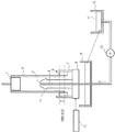
図1に示すように、本発明の塗膜除去方法に用いられる塗膜除去装置は、電子写真感光体用塗布液の塗膜が形成された円筒状の基体2を鉛直方向に支持する基体保持部材1を備えている。また該塗膜除去装置は、基体保持部材1によって支持された基体2の軸方向(長手方向)下方の外周面に形成された塗膜(被除去部の塗膜)を除去する塗膜除去機構を備えている。
As shown in FIG. 1, the coating film removing apparatus used in the coating film removing method of the present invention is a substrate holding device that supports a
塗膜除去機構は支持体8を有する。支持体8は、基体2内に挿入可能に垂直に立設された軸部15と、外周面塗膜除去部材6を保持する外周面塗膜除去部材用保持部材7と、を有している。回転モーター13により支持体8を回転させることで、軸部15の軸線回りに軸部15と外周面塗膜除去部材用保持部材7とを一体に回転可能となっている。
The coating film removal mechanism has a
外周面塗膜除去部材用保持部材7には、硬度の異なる複数の除去部(詳細を後述する第1の除去部6aおよび第2の除去部6b)を有する外周面塗膜除去部材6が取り付けられている。外周面塗膜除去部材6が有する複数の除去部は、基体2の外周面に当接可能に構成されている。外周面塗膜除去部材6が有する複数の除去部が基体2の外周面に当接した状態で、支持体8を回転させると、外周面塗膜除去部材6が有する複数の除去部が基体2の外周面を摺擦し、基体2の外周面に存在している不要な塗膜を除去することができる。
The outer peripheral surface coating film removing
軸部15は、その内部に軸部15を貫通する溶剤供給流路4を有し、上端部には溶剤11が吐出される開口である溶剤供給口3を有している。溶剤11は、溶剤供給タンク10より溶剤供給ポンプ12によって支持体8へ送られ、軸部15の内部に設けられた溶剤供給流路4を通って溶剤供給口3から吐出される。
The
また、溶剤供給口3から吐出された溶剤11を回収する溶剤回収タンク9が設けられ、溶剤回収タンク9で回収された使用済みの溶剤11は、必要に応じて精製等された後、溶剤供給タンク10に送られて、再利用される構成になっている。
Further, a solvent recovery tank 9 for recovering the solvent 11 discharged from the
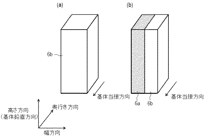
つぎに、第1の除去部6aおよび第2の除去部6bを有する外周面塗膜除去部材6の詳細な形状の一例を、図2(a)および図2(b)を用いて説明する。
図2(a)および図2(b)は、本発明の塗膜除去方法に用いられる外周面塗膜除去部材の除去部の形状の一例を示す斜視図である。本発明の外周面塗膜除去部材は、硬度の異なる第1の除去部と第2の除去部とを有する。図2(a)および図2(b)の例において、第1の除去部および第2の除去部はブレード状(直方体形状)である。
Next, an example of the detailed shape of the outer peripheral surface coating
2 (a) and 2 (b) are perspective views showing an example of the shape of the removal portion of the outer peripheral surface coating film removing member used in the coating film removing method of the present invention. The outer peripheral surface coating film removing member of the present invention has a first removing portion and a second removing portion having different hardnesses. In the example of FIG. 2A and FIG. 2B, the first removal portion and the second removal portion have a blade shape (cuboid shape).
図2(a)は、1枚のブレードが1種類のブレード硬度を有する第2の除去部6bを示す。図2(a)で示される第2の除去部6bを用いる場合は、第2の除去部6bとは異なる硬度を有する第1の除去部6aが別に(離間して)設けられている。したがって、外周面塗膜除去部材6は、ブレード硬度が異なる第1の除去部6aと、第2の除去部6bとからなり、複数の除去部(6a,6b)が別体構成をとる。なお、このとき、外周面塗膜除去部材6は第1の除去部6aおよび第2の除去部6bのみからなるものに限られず、さらに他の除去部を有していてもよい。例えば、それぞれが別体として設けられ、離間して配置された3つ以上の除去部(いずれも同一の硬度であるものは除く)を有する外周面塗膜除去部であってもよい。
FIG. 2A shows a
図2(b)は、硬度の異なる複数のブレードである第1の除去部6aと第2の除去部6bとが、一体でまたは互いに接して外周面塗膜除去部材6を構成している。一体構成とは、例えば、1つのブレードの一部に架橋などによる硬化を施し、この硬化した一部の硬度を他の部分の硬度と異ならしめることで、一体でありながらも異なる硬度の部位が存在する構成をいう。また、互いに接した構成とは、例えば、互いに異なる硬度を有する2つのブレードが接着剤等により接した構成をいう。なお、このとき、外周面塗膜除去部材6は第1の除去部6aおよび第2の除去部6bのみからなるものに限られるものではなく、さらに他の除去部を有していてもよい。例えば、一体でまたは互いに接して設けられた3つ以上の除去部を有する外周面塗膜除去部であってもよく、一体でまたは互いに接して設けられた2つ以上の除去部を複数有し、これらが互いに離間してなる外周面塗膜除去部であってもよい。ただし、いずれも同一の硬度であるものは除く。
In FIG. 2B, the outer peripheral surface coating
硬度がより高い第1の除去部6aは、基体2の被除去部から塗膜を除去する力がより強いため、基体2に強固に付着した塗膜も除去が可能であるという利点がある。一方、硬度がより低い第2の除去部6bは、基体2の被除去部との接触がより均一になるため、基体2上の塗膜を除去残りなく除去することが可能であるという利点がある。本発明においては、硬度が異なる除去部(硬度がより高い第1の除去部6aと硬度がより低い第2の除去部6bと)を用いて除去を行うことで、両方の利点を生かした塗膜除去が可能となるため、塗膜除去の精度が相乗的に高められる。
The first removing
硬度の異なる複数の除去部の構成については、複数の除去部を、別体で構成する、一体で若しくは互いに接して構成する、または、これらを組み合わせた構成にするなど、特に限定されず適宜選択が可能であり、何れの場合においても塗膜除去性は向上する。 The configuration of the plurality of removal portions having different hardnesses is not particularly limited and may be appropriately selected, such as a configuration in which the plurality of removal portions are configured separately, configured integrally or in contact with each other, or a combination thereof. In any case, the coating film removability is improved.
本発明において、外周面塗膜除去部材6における硬度は、JIS K 6253のデュロメータタイプAで測定できる。硬度がより高い第1の除去部6aと硬度がより低い第2の除去部6bとの硬度差は、20°以上であることが、上記両者の利点を効率よく得られるため好ましい。また、硬度がより高い第1の除去部6aの硬度は、60°以上であることが好ましく、80°以上であることがより好ましい。硬度がより低い第2の除去部6bの硬度は、60°未満であることが好ましく、40°以下であることがより好ましい。
In the present invention, the hardness of the outer peripheral surface coating
外周面塗膜除去部材6の第1の除去部6a、第2の除去部6bの材質は、耐摩耗性および耐溶剤性を考慮して選択でき、例えば、ポリエチレン、ポリエステル、ポリプロピレン、ポリイミド等の樹脂、エチレンプロピレンゴム、エチレンプロピレンジエンゴム、ブチルゴム、フッ素系ゴム等のゴムを使用することができる。
The material of the
外周面塗膜除去部材6の第1の除去部6a、第2の除去部6bの形状としては、当接部へ溶剤がしみ上がりやすいこと、連続使用時に汚れが塗膜除去部材に溜まりにくいこと、塗膜を除去する面と除去しない面との境界が乱れにくいなどの点から、ブレード状であることが好ましい。
As the shape of the
ここで、図2(a)および図2(b)に示す外周面塗膜除去部材6の第1の除去部6a、第2の除去部6bは、ブレード状(直方体形状)であり、その一面の垂線方向が基体2との当接方向となっている。ただし、本発明はこれに何ら限定されるものではなく、第1の除去部6a、第2の除去部6bは、それぞれ任意の角度で基体2と当接することができる。
Here, the
本発明の塗膜除去方法について、一連の工程を図1の塗膜除去装置を例に説明する。
まず、浸漬塗布法により外周面に電子写真感光体用塗布液の塗膜が形成された円筒状の基体2を、基体保持部材1によって鉛直方向に支持する。
With respect to the coating film removing method of the present invention, a series of steps will be described using the coating film removing apparatus of FIG. 1 as an example.
First, a
次に、基体2の塗膜除去を実施する領域(「被除去部」とも記載する。)の上端が、外周面塗膜除去部材6の基体2との当接部上端(第1の除去部6aの上端および第2の除去部6bの上端)と同じ高さになる位置まで基体2を下降し、軸部15を挿入する(外周面塗膜除去部材当接工程)。このとき、基体2の軸方向下方の外周面である被除去部の塗膜の上端から下端まで、第1の除去部6aおよび第2の除去部6bがそれぞれ当接する。
また、溶剤供給ポンプ12を作動させ、溶剤供給口3から溶剤11を吐出させることにより、円筒状の基体2の内部に溶剤11を供給する。
Next, the upper end of the region where the coating film removal of the
Further, the
そして、この状態で溶剤11を吐出させながら回転モーター13により支持体8を回転させることで、当接させた外周面塗膜除去部材6の第1の除去部6aおよび第2の除去部6bを回転させ、不要な塗膜を摺擦し、除去を実施する(外周面塗膜除去工程)。外周面塗膜除去工程では、被除去部の塗膜の上端から下端まで第1の除去部6aおよび第2の除去部6bを当接させたまま、溶剤11を、該被除去部の塗膜と第1の除去部6aおよび第2の除去部6bとの当接部に供給しながら、摺擦によって該被除去部の塗膜を除去する。
そして、所定の時間回転させた後、基体2を引き上げて、一連の塗膜除去工程が終了する。
In this state, the first removing
And after rotating for a predetermined time, the base |
なお、図1に示す塗膜除去装置では第1の除去部6aおよび第2の除去部6bが回転しているが、本発明はこれに限られるものではない。第1の除去部6aおよび第2の除去部6bと、基体2とが相対的に回転して摺擦し、被除去部の塗膜を除去できればよい。したがって、第1の除去部6aおよび第2の除去部6bが回転してもよく、基体2が回転してもよく、第1の除去部6aおよび第2の除去部6bと、基体2との双方が回転してもよい。
In addition, although the
ここで、図3〜図6に本発明の塗膜除去方法に用いられる外周面塗膜除去部材および基体の配置構成の例を示し、塗膜除去の際のこれらの回転駆動状態を、具体例を挙げて説明する。
図3に示す外周面塗膜除去部材6は、図2(a)に示したブレード状の第2の除去部6bと、第2の除去部6bと同形状の第1の除去部6aとからなり、円筒状の基体2の軸を中心として対称に設けられている。すなわち、図3に示す上面図において、第1の除去部6aと、第2の除去部6bと、基体2の中心とは、一直線上に配置されている。図3に示す例では、第1の除去部6aと第2の除去部6bとが任意の方向に回転してもよく、基体2が任意の方向に回転してもよい。
Here, FIG. 3 to FIG. 6 show examples of the arrangement configuration of the outer peripheral surface coating film removing member and the substrate used in the coating film removing method of the present invention, and specific examples of these rotational driving states at the time of coating film removal are shown. Will be described.
The outer peripheral surface coating
図4に示す外周面塗膜除去部材6は、図2(b)に示した互いに接して構成されている第1の除去部6aと第2の除去部6bとの組み合わせを2つ有しており、これらは円筒状の基体2の軸を中心として対称に設けられている。図4に示す例では、第1の除去部6aと第2の除去部6bとが、円筒状の基体2の中心を回転軸として反時計回り方向に回転する。なお、第2の除去部6bと比較して硬度が高い第1の除去部6aが、回転先頭側に設けられ、第1の除去部6aと比較して硬度が低い第2の除去部6bが回転後尾側に設けられている。
The outer peripheral surface coating
図5に示す外周面塗膜除去部材6は、図2(b)に示した互いに接して構成されている第1の除去部6aと第2の除去部6bとの組み合わせを2つ有しており、これらは円筒状の基体2の軸を中心として対称に設けられている。図5に示す例では、第1の除去部6aと第2の除去部6bとが、円筒状の基体2の中心を回転軸として時計回り方向に回転する。なお、第2の除去部6bと比較して硬度が高い第1の除去部6aが、回転後尾側に設けられ、第1の除去部6aと比較して硬度が低い第2の除去部6bが回転先頭側に設けられている。複数の除去部は、回転先頭側の一方の除去部の硬度が、回転後尾側の他方の除去部の硬度よりも低いことが好ましい。
The outer peripheral surface coating
図6に示す外周面塗膜除去部材6は、図2(b)に示した互いに接して構成されている第1の除去部6aと第2の除去部6bとの組み合わせを、2つ有しており、これらは円筒状の基体2の軸を中心として対称に設けられている。図6に示す例では、円筒状の基体2がその中心を回転軸として反時計回り方向に回転する。なお、第2の除去部6bと比較して硬度が高い第1の除去部6aが、回転下流側に設けられ、第1の除去部6aと比較して硬度が低い第2の除去部6bが回転上流側に設けられている。複数の除去部は、回転上流側の一方の除去部の硬度が、回転下流側の他方の硬度よりも低いことが好ましい。
The outer peripheral surface coating
図1に示す塗膜除去装置では、溶剤供給工程で溶剤11が基体2の内部に吐出される。この吐出された溶剤11は、軸部15の上部を構成するテーパ面(下方に向かって漸次径が大きくなる形状)を経由して、基体2の内周面に至る。ついで、溶剤11が基体2の内周面を流れ落ちて基体2の下端部に達する。そして、溶剤11が、基体2の下端部から、第1の除去部6aおよび第2の除去部6bと基体2の軸方向下方にある被除去部の塗膜との当接部における微小空間をしみ上がることで、塗膜除去を実施する領域に溶剤11が供給される。
In the coating film removing apparatus shown in FIG. 1, the solvent 11 is discharged into the
なお、一連の塗膜除去の工程では、外周面塗膜除去工程において第1の除去部6aおよび第2の除去部6bを摺擦しているときに、溶剤11を常に吐出してもよいし、断続的に吐出してもよい。また、基体2を所定位置に移動するために上下動させているときなど、外周面塗膜除去工程の前や後に、吐出していてもよい。すなわち、塗膜除去を実施する領域に溶剤11が充分に供給されるのであれば、溶剤11を溶剤供給口3から吐出するタイミングは、任意のものとすることができる。
In the series of coating film removing steps, the solvent 11 may be always discharged when the first removing
この塗膜除去方法では、第1の除去部6aおよび第2の除去部6bで塗膜を摺擦しているときに、溶剤11を当接部に供給できる。そのため、当接部に溶剤を供給しながら塗膜を除去する方法ではない方法、例えば、あらかじめ除去部材に一旦染み込ませた溶剤だけで塗膜を除去する方法などに比べて、この塗膜除去方法では効率的な除去が可能となる。なお、特許文献2では、基体の外周面の被除去部よりも基体の軸方向において短い塗膜除去部材を用いて、昇降を繰り返して塗膜を除去している。従って、特許文献2に記載された装置は、本発明のように基体の外周面の被除去部の塗膜の上端から下端まで外周面塗膜除去部材を当接させたまま溶剤を当接部に供給しながら塗膜を除去する構成ではない。
In this coating film removing method, the solvent 11 can be supplied to the contact portion when the coating film is rubbed with the first removing
さらに、図1に示す塗膜除去装置を用いた塗膜除去方法では、基体2の内部において溶剤が吐出されるため、除去する必要のない塗膜の部分にまで溶剤が飛び散りにくい。そのため、外周面塗膜除去部材の除去部と基体の被除去部の塗膜との当接部に対してノズルなどで直接的に溶剤を供給する方法や、外周面塗膜除去部材や基体下端部を溶剤中に浸漬させながら摺擦する方法に比べて、溶剤の飛び散りが少ない正確な除去が可能となる。
Furthermore, in the coating film removing method using the coating film removing apparatus shown in FIG. 1, since the solvent is discharged inside the
第1の除去部6aおよび第2の除去部6bと基体2の被除去部の塗膜との当接部における微小空間で溶剤11をしみ上がらせるために、基体2の下端とほぼ同じ位置において第1の除去部6aおよび第2の除去部6bが当接している必要がある。ただし、第1の除去部6aおよび第2の除去部6bの下端が基体2の下端よりわずかに上に位置していても、溶剤11が基体2の外周面に回り込める程度であれば、溶剤11は微小空間にしみ上がることができる。なお、第1の除去部6aおよび第2の除去部6bは基体2の下端よりも下方に延伸した構成であってもよい。第1の除去部6aおよび第2の除去部6bの下端が基体2の下端より下方に位置していると、溶剤11が当接部をしみ上がりやすく、塗膜除去が効率的になるので好ましい。
In order to soak up the solvent 11 in a minute space at the contact portion between the
塗膜除去を行う位置まで基体2を下降するときには、基体2の外周面に外周面塗膜除去部材6が接触しないように、外周面塗膜除去部材6を基体2の半径方向の外側方向に移動させて退避させることが好ましい。そのため、外周面塗膜除去部材用保持部材7は、図示していない動作機構により、基体2の半径方向の外側方向に外周面塗膜除去部材6が接触しない位置まで移動可能となっていることが好ましい。
When the
詳細な動作としては、基体2を下降して移動している間は、基体2の外周面に外周面塗膜除去部材6が接触しないように、外周面塗膜除去部材用保持部材7を基体2の半径方向の外側方向に移動させて退避させる。次に、所定の位置まで基体2を下降し、移動を停止した後、外周面塗膜除去部材用保持部材7を基体2の半径方向の内側方向に移動し、外周面塗膜除去部材6の第1の除去部6aおよび第2の除去部6bを基体2の外周面に当接させる。そして、支持体8を回転させて塗膜除去を行う。外周面塗膜除去部材用保持部材7を基体2の半径方向の外側方向に移動させずに基体2を下降させると、基体2が第1の除去部6aおよび第2の除去部6bの上端部分に接触して押圧するため、第1の除去部6aおよび第2の除去部6bの摩耗や変形が起こりやすくなり、塗膜を除去する境界が乱れやすくなる。
As a detailed operation, the outer peripheral surface coating film removing
また、溶剤の供給方法としては、上記のような方法の他に、溶剤中に基体の下端部や外周面除去部材を浸漬して供給する方法や、外周面除去部材の除去部と基体の被除去部の塗膜との当接部に溶剤が供給されるように、ノズルなどで直接供給する方法などが挙げられる。溶剤の飛び散りの観点から、図1に示す塗膜除去装置を用いた塗膜除去方法が好ましい。 In addition to the methods described above, the solvent may be supplied by immersing the lower end of the substrate or the outer peripheral surface removing member in the solvent, or by supplying the outer peripheral surface removing member to the substrate. For example, a method of directly supplying with a nozzle or the like so that the solvent is supplied to the contact portion of the removing portion with the coating film. From the viewpoint of scattering of the solvent, a coating film removing method using the coating film removing apparatus shown in FIG. 1 is preferable.
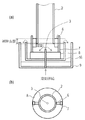
溶剤中に基体の下端部や外周面除去部材を浸漬して供給する具体例を、図7を用いて説明する。図7は、本発明の塗膜除去方法に用いられる塗膜除去装置の一例における除去部の近傍の概略構成を示す断面図(図7(a))および上面図(図7(b))である。図1と同一部材には同じ符号を付し、これらの構成は図1と同様であるためその説明は省略する。 A specific example in which the lower end portion of the base and the outer peripheral surface removal member are supplied in a solvent will be described with reference to FIG. FIG. 7 is a cross-sectional view (FIG. 7 (a)) and a top view (FIG. 7 (b)) showing a schematic configuration in the vicinity of the removing portion in an example of a coating film removing apparatus used in the coating film removing method of the present invention. is there. The same members as those in FIG. 1 are denoted by the same reference numerals, and the configuration thereof is the same as that in FIG.
図7に示す塗膜除去装置は、一時的に溶剤11を貯留する溶剤貯留部16を有している。そして、このような塗膜除去装置では、溶剤供給タンク10から溶剤供給ポンプ12によって送られた溶剤11が、溶剤供給口3から吐出されて溶剤貯留部16に一時的に貯留され、オーバーフローするようになっている。オーバーフローした溶剤11は溶剤回収タンク9で回収され、図1と同様に溶剤供給タンク10に送られ、再利用される。基体2の下端部および外周面塗膜除去部材6(第1の除去部6aおよび第2の除去部6b)の下端部が溶剤貯留部16の内部の溶剤に接触(浸漬)されるようになっており、基体2の軸方向下方の塗膜と外周面塗膜除去部材6との当接部に溶剤11が供給される。
The coating film removing apparatus shown in FIG. 7 has a
本発明の塗膜除去方法で使用する溶剤11としては、特に限定されないが、塗膜を溶解または膨潤し得るものが望ましい。また、溶剤11は、基体2の軸方向下方の塗膜と外周面塗膜除去部材6とで形成される微小空間の壁面に対して充分に濡れ、微小空間の上端までしみ上がり得るような表面張力を有するものであることが望ましい。溶剤11は1種のみを用いてもよく、2種以上を混合して用いてもよい。
Although it does not specifically limit as the solvent 11 used with the coating-film removal method of this invention, The thing which can melt | dissolve or swell a coating film is desirable. Further, the surface of the solvent 11 is sufficiently wetted with respect to the wall surface of the minute space formed by the coating film on the lower side in the axial direction of the
また、回転モーター13により支持体8を回転する速度は、適宜設定すればよい。回転速度が大きいほど除去にかかる時間が短く済むが、あまりに大きすぎると外周面塗膜除去部材6に負荷がかかりすぎて、外周面塗膜除去部材6が変形したり切れ目が入ったりする場合がある。
Moreover, what is necessary is just to set the speed which rotates the
基体2上に浸漬塗布法を用いて複数の層が形成される場合には、本発明の塗膜除去方法は、必要に応じて、基体2上に形成される各層のうち一部の層についてのみ実施してもよいし、全部の層について実施してもよい。また、複数の層について本発明の塗膜除去方法を行う場合は、各層の塗膜を形成するたびに塗膜を除去してもよいし、いくつかの乾燥塗膜を順次形成した後、一度に塗膜を除去してもよい。
When a plurality of layers are formed on the
基体2の軸方向(鉛直方向)下方の内周面の塗膜を効率的に除去するために、例えば図8(a)および図8(b)に示すように、塗膜除去部材として外周面塗膜除去部材6に追加して、内周面塗膜除去部材5を用いてもよい。
In order to efficiently remove the coating film on the inner peripheral surface below the axial direction (vertical direction) of the
内周面塗膜除去部材5を用いなくても、例えば基体2内部に溶剤を供給することによって基体2内部の塗膜(すなわち基体2内周面の塗膜)の除去を行うことはできるが、内周面塗膜除去部材5を設け、溶剤11を供給しながら塗膜を摺擦する方が、精度よく短時間で塗膜を除去できる。
Even without using the inner peripheral surface coating
また、図1の塗膜除去装置では外周面塗膜除去部材6に供給される溶剤11は基体2内面を伝わって供給される。したがって、基体2内面が汚れていると、汚れた溶剤11が外周面に供給されることになる。そのため、内周面塗膜除去部材5を設け、精度よく短時間で基体2内面の塗膜を除去した方が、外周面の塗膜の除去精度が良好になる。
In the coating film removing apparatus shown in FIG. 1, the solvent 11 supplied to the outer peripheral surface coating
内周面塗膜除去部材5を設けた場合の例について、図8を用いてより詳細に説明する。図8は、本発明の塗膜除去方法に用いられる塗膜除去装置の一例における除去部の近傍の概略構成を示す断面図(図8(a))および上面図(図8(b))である。図8において、図1と同一部材には同じ符号を付し、これらの構成は図1と同様であり、その説明は省略する。
An example in which the inner peripheral surface coating
図8(a)および図8(b)に示す塗膜除去装置は2つの内周面塗膜除去部材5を有する。内周面塗膜除去部材5は軸部15の側面に取り付けられており、軸部15と一緒に回転可能となっている。内周面塗膜除去部材5は、軸部15を基体2に挿入したときに、基体2の内周面に接触するようになっており、支持体8および軸部15を回転させることで基体2内面を摺擦して、基体2内周面に存在している不要な塗膜を除去することができる。したがって、図8に示す内周面塗膜除去部材5を有する塗膜除去装置を用いて本発明の塗膜除去方法を行うと、基体2の内周面の塗膜に内周面塗膜除去部材5を当接する工程(内周面塗膜除去部材当接工程)も行うことができる。また、基体2の内周面の塗膜に内周面塗膜除去部材5を当接させたまま、基体2と内周面塗膜除去部材5とを相対的に回転させて摺擦し、内周面の塗膜を除去する工程(内周面塗膜除去工程)も行うことができる。なお、図8においては、外周面塗膜除去部材6を有する支持体8に設けられた軸部15に内周面塗膜除去部材5が取り付けられているため、内周面塗膜除去工程は、外周面塗膜除去工程と同時に行われることになる。
The coating film removing apparatus shown in FIGS. 8A and 8B has two inner peripheral surface coating
内周面塗膜除去部材5を設ける場合は、図8(a)および図8(b)に示すように、基体2と内周面塗膜除去部材5との内周面当接部と、基体2と外周面塗膜除去部材6との外周面当接部のそれぞれが、基体2の円周上の異なる位置であることが好ましい。それぞれの当接部が基体2の円周上の同じ位置にある場合、図8(a)および図8(b)のように異なる位置にある場合と比べて、内周面塗膜除去部材5により溶剤11の流れが妨げられ、外周面塗膜除去部材6に供給される溶剤11の量が減る。そのため、それぞれの当接部が円周上の異なる位置にあることが好ましい。なお、内周面当接部と外周面当接部とが、基体2の円周上の同じ位置にあるとは、基体2の円周の中心から同一半径方向に内周面塗膜除去部材5と外周面塗膜除去部材6とが設けられていること、即ち、内周面当接部と外周面当接部とが、基体2を介して対向していることをいう。
When providing the inner peripheral surface coating
内周面塗膜除去部材5の材質は、耐摩耗性および耐溶剤性を考慮して選択できる。上記外周面塗膜除去部材と同様に、例えば、ポリエチレン、ポリエステル、ポリプロピレン、ポリイミド等の樹脂、エチレンプロピレンゴム、エチレンプロピレンジエンゴム、ブチルゴム、フッ素系ゴム等のゴムを使用することができる。
The material of the inner peripheral surface coating
内周面塗膜除去部材5の形状は、ブレード状、ブラシ状、不織布などの布状体など特に限定されず適宜選択可能である。連続使用時に汚れが内周面塗膜除去部材5に溜まりにくいことなどの点からブレード状のものが好ましい。
The shape of the inner peripheral surface coating
次に、上記塗膜除去方法を用いた本発明の電子写真感光体の製造方法について、説明する。
本発明の電子写真感光体の製造方法で製造される電子写真感光体は、円筒状の基体と、基体上に形成された電荷発生物質および電荷輸送物質を含有する感光層と、を有する。感光層は、基体側から電荷発生物質を含有する電荷発生層と電荷輸送物質を含有する電荷輸送層とをこの順に積層してなるもの(積層型感光層)でも、電荷発生物質および電荷輸送物質を同一の層に含有させてなるものでも(単層型感光層)よい。基体上に感光層を直接設けると、感光層の剥がれが生じたり、基体の表面の欠陥(傷などの形状的欠陥または不純物などの材質的欠陥)が画像にそのまま反映され、黒点状や白抜け状の画像欠陥が生じたりする場合がある。これらの問題を解消するために、下引き層を感光層と基体との間に有することが好ましい。
Next, a method for producing the electrophotographic photosensitive member of the present invention using the coating film removing method will be described.
An electrophotographic photoreceptor produced by the method for producing an electrophotographic photoreceptor of the present invention has a cylindrical substrate and a photosensitive layer containing a charge generating material and a charge transport material formed on the substrate. Even if the photosensitive layer is formed by laminating a charge generation layer containing a charge generation material and a charge transport layer containing a charge transport material in this order (laminated photosensitive layer), the charge generation material and the charge transport material (Single-layer type photosensitive layer) may be used. If the photosensitive layer is directly provided on the substrate, the photosensitive layer may be peeled off, or defects on the surface of the substrate (geometric defects such as scratches or material defects such as impurities) are directly reflected in the image, resulting in black spots or white spots. Image defects may occur. In order to solve these problems, it is preferable to have an undercoat layer between the photosensitive layer and the substrate.
〔円筒状の基体〕
円筒状の基体としては、導電性を有するもの(導電性基体)が好ましく、例えば、アルミニウム、ニッケル、銅、金、鉄などの金属又は合金製の基体を用いることができる。また、これら以外にも、ポリエステル樹脂、ポリカーボネート樹脂、ポリイミド樹脂、ガラスなどの絶縁性基体上にアルミニウム、銀、金などの金属の薄膜を形成した基体、又は酸化インジウム、酸化スズなどの導電性材料の薄膜を形成した基体が挙げられる。
円筒状の基体の表面には、電気的特性の改善や干渉縞の抑制のため、陽極酸化などの電気化学的な処理や、湿式ホーニング処理、ブラスト処理、切削処理などを施してもよい。
[Cylindrical substrate]
As the cylindrical substrate, a conductive substrate (conductive substrate) is preferable. For example, a substrate made of metal or alloy such as aluminum, nickel, copper, gold, iron, or the like can be used. In addition to these, a base in which a thin film of metal such as aluminum, silver or gold is formed on an insulating base such as polyester resin, polycarbonate resin, polyimide resin or glass, or a conductive material such as indium oxide or tin oxide. And a substrate on which the thin film is formed.
The surface of the cylindrical substrate may be subjected to electrochemical treatment such as anodic oxidation, wet honing treatment, blast treatment, cutting treatment, etc. in order to improve electrical characteristics and suppress interference fringes.
〔導電層(第一中間層)〕
基体と後述する下引き層との間に、導電層を設けてもよい。導電層は、導電性粒子を樹脂および溶剤とともに分散させた導電層用塗布液(第一中間層用塗布液)の塗膜を基体上に形成し、塗膜を乾燥させることで得られる。導電性粒子としては、例えば、アセチレンブラックのようなカーボンブラックや、アルミニウム、ニッケル、鉄、ニクロム、銅、亜鉛、銀のような金属粉や、導電性酸化スズ、ITO(Indium Tin Oxide)のような金属酸化物粉体が挙げられる。
また、樹脂としては、例えば、ポリエステル樹脂、ポリカーボネート樹脂、ポリビニルブチラール樹脂、アクリル樹脂、シリコーン樹脂、エポキシ樹脂、メラミン樹脂、ウレタン樹脂、フェノール樹脂およびアルキッド樹脂が挙げられる。
導電層用塗布液の溶剤としては、例えば、エーテル系溶剤、アルコール系溶剤、ケトン系溶剤および芳香族炭化水素溶剤が挙げられる。
[Conductive layer (first intermediate layer)]
A conductive layer may be provided between the base and the undercoat layer described later. The conductive layer is obtained by forming a coating film of a conductive layer coating liquid (first intermediate layer coating liquid) in which conductive particles are dispersed together with a resin and a solvent on a substrate and drying the coating film. Examples of the conductive particles include carbon black such as acetylene black, metal powder such as aluminum, nickel, iron, nichrome, copper, zinc, and silver, conductive tin oxide, and ITO (Indium Tin Oxide). Metal oxide powder.
Examples of the resin include polyester resin, polycarbonate resin, polyvinyl butyral resin, acrylic resin, silicone resin, epoxy resin, melamine resin, urethane resin, phenol resin, and alkyd resin.
Examples of the solvent for the conductive layer coating solution include ether solvents, alcohol solvents, ketone solvents, and aromatic hydrocarbon solvents.
〔下引き層(第二中間層)〕
基体側からの感光層側への電荷注入を抑制し、カブリなどの画像欠陥の発生を抑制することを目的として、基体と感光層との間には下引き層が設けられている。
下引き層としては、ポリアミド等の結着樹脂からなる層、結着樹脂に金属酸化物を分散させた層、電子輸送物質を含有させた層などが挙げられる。
[Undercoat layer (second intermediate layer)]
An undercoat layer is provided between the substrate and the photosensitive layer for the purpose of suppressing charge injection from the substrate side to the photosensitive layer side and suppressing the occurrence of image defects such as fog.
Examples of the undercoat layer include a layer made of a binder resin such as polyamide, a layer in which a metal oxide is dispersed in the binder resin, and a layer containing an electron transport material.
電子輸送物質を含有する下引き層の製造方法としては、例えば、まず重合性官能基を有する電子輸送物質、架橋剤及び熱可塑性樹脂、並びに場合によっては溶剤、シリカ粒子を含有する下引き層用塗布液(第二中間層用塗布液)の塗膜を形成する。そして、この塗膜を加熱乾燥させることによって、重合性官能基を有する電子輸送物質、架橋剤を重合させ、下引き層を形成することができる。 Examples of a method for producing an undercoat layer containing an electron transport material include, for example, an electron transport material having a polymerizable functional group, a crosslinking agent and a thermoplastic resin, and optionally a solvent and an undercoat layer containing silica particles. A coating film of the coating solution (second intermediate layer coating solution) is formed. And by heating-drying this coating film, the electron transport substance which has a polymeric functional group, and a crosslinking agent can be superposed | polymerized and an undercoat layer can be formed.
電子輸送物質としては、例えば、キノン化合物、イミド化合物、ベンズイミダゾール化合物、シクロペンタジエニリデン化合物が挙げられる。重合性官能基としては、ヒドロキシ基、チオール基、アミノ基、カルボキシ基、メトキシ基が挙げられる。重合性官能基は、電子輸送を担う骨格構造に直接結合しても、側鎖(電子輸送を担う骨格構造に結合した置換基)中に存在してもよい。 Examples of the electron transport material include a quinone compound, an imide compound, a benzimidazole compound, and a cyclopentadienylidene compound. Examples of the polymerizable functional group include a hydroxy group, a thiol group, an amino group, a carboxy group, and a methoxy group. The polymerizable functional group may be directly bonded to the skeleton structure responsible for electron transport or may be present in the side chain (substituent bonded to the skeleton structure responsible for electron transport).
架橋剤としては、重合性官能基を有する電子輸送物質や、熱可塑性樹脂と重合又は架橋する化合物が挙げられる。具体的には、山下晋三,金子東助編「架橋剤ハンドブック」大成社刊(1981年)等に記載されている化合物等が挙げられる。 Examples of the crosslinking agent include an electron transport material having a polymerizable functional group and a compound that polymerizes or crosslinks with a thermoplastic resin. Specific examples include compounds described in Shinzo Yamashita, Tosuke Kaneko “Crosslinking Agent Handbook” published by Taiseisha (1981), and the like.
下引き層に用いる架橋剤は、好ましくは、イソシアネート化合物、アミン化合物である。イソシアネート基又はブロックイソシアネート基を2〜6個有しているイソシアネート化合物が好ましい。例えば、トリイソシアネートベンゼン、トリイソシアネートメチルベンゼン、トリフェニルメタントリイソシアネート、リジントリイソシアネートの他、トリレンジイソシアネート、ヘキサメチレンジイソシアネート、ジシクロヘキシルメタンジイソシアネート、ナフタレンジイソシアネート、ジフェニルメタンジイソシアネート、イソホロンジイソシアネート、キシリレンジイソシアネート、2,2,4−トリメチルヘキサメチレンジイソシアネート、メチル−2,6−ジイソシアネートヘキサノエート、ノルボルナンジイソシアネート等のジイソシアネートのイソシアヌレート変性体、ビウレット変性体、アロファネート変性体、トリメチロールプロパンやペンタエリスリトールとのアダクト変性体等が挙げられる。これらの中でもイソシアヌレート変性体とアダクト変性体がより好ましい。
ブロックイソシアネート基は、−NHCOX1(X1は保護基)という構造を有する基である。X1は、イソシアネート基に導入可能な保護基であれば何れでもよい。
熱可塑性樹脂としては、例えば、ポリビニルアセタール樹脂、ポリオレフィン樹脂、ポリエステル樹脂、ポリエーテル樹脂、ポリアミド樹脂が挙げられる。
シリカ粒子としては、ゾルゲル法、水ガラス法などの湿式法や、気相法等の乾式法によって得られるシリカ粒子が挙げられる。また、添加時のシリカ粒子の形状は粉状であってもよいし、溶媒に分散されたスラリー状の状態で添加してもよい。
下引き層用塗布液に用いられる溶剤は、アルコール系溶剤、スルホキシド系溶剤、ケトン系溶剤、エーテル系溶剤、エステル系溶剤および芳香族炭化水素溶剤などが挙げられる。
The crosslinking agent used for the undercoat layer is preferably an isocyanate compound or an amine compound. An isocyanate compound having 2 to 6 isocyanate groups or blocked isocyanate groups is preferred. For example, triisocyanate benzene, triisocyanate methylbenzene, triphenylmethane triisocyanate, lysine triisocyanate, tolylene diisocyanate, hexamethylene diisocyanate, dicyclohexylmethane diisocyanate, naphthalene diisocyanate, diphenylmethane diisocyanate, isophorone diisocyanate, xylylene diisocyanate, 2, Isocyanurate-modified products, biuret-modified products, allophanate-modified products of diisocyanates such as 2,4-trimethylhexamethylene diisocyanate, methyl-2,6-diisocyanate hexanoate, norbornane diisocyanate, adduct-modified products with trimethylolpropane and pentaerythritol Etc. Among these, an isocyanurate modified body and an adduct modified body are more preferable.
The blocked isocyanate group is a group having a structure of —NHCOX 1 (X 1 is a protecting group). X 1 may be any protecting group that can be introduced into an isocyanate group.
Examples of the thermoplastic resin include polyvinyl acetal resin, polyolefin resin, polyester resin, polyether resin, and polyamide resin.
Examples of the silica particles include silica particles obtained by a wet method such as a sol-gel method or a water glass method, or a dry method such as a gas phase method. Moreover, the shape of the silica particles at the time of addition may be powdery, or may be added in the form of a slurry dispersed in a solvent.
Examples of the solvent used in the coating solution for the undercoat layer include alcohol solvents, sulfoxide solvents, ketone solvents, ether solvents, ester solvents, and aromatic hydrocarbon solvents.
〔電荷発生層(積層型感光層の場合)〕
電荷発生層は、基体上、導電層上または下引き層上に設けられる。
電荷発生層は、電荷発生物質を結着樹脂および溶剤とともに分散して得られる電荷発生層用塗布液の塗膜を形成し、塗膜を乾燥させることによって形成することができる。
分散方法としては、例えば、ホモジナイザー、超音波、ボールミル、サンドミル、アトライター、ロールミルを用いた方法が挙げられる。
[Charge generation layer (in the case of laminated photosensitive layer)]
The charge generation layer is provided on the substrate, the conductive layer, or the undercoat layer.
The charge generation layer can be formed by forming a coating film of a coating solution for a charge generation layer obtained by dispersing a charge generation material together with a binder resin and a solvent, and drying the coating film.
Examples of the dispersion method include a method using a homogenizer, an ultrasonic wave, a ball mill, a sand mill, an attritor, and a roll mill.
電荷発生物質としては、アゾ顔料、ペリレン顔料、アントラキノン誘導体、アントアントロン誘導体、ジベンズピレンキノン誘導体、ピラントロン誘導体、ビオラントロン誘導体、イソビオラントロン誘導体、インジゴ誘導体、チオインジゴ誘導体、金属フタロシアニン、無金属フタロシアニンなどのフタロシアニン顔料や、ビスベンズイミダゾール誘導体などが挙げられる。これらの中でも、アゾ顔料、及びフタロシアニン顔料の少なくとも一方が好ましい。フタロシアニン顔料の中でも、オキシチタニウムフタロシアニン、クロロガリウムフタロシアニン、ヒドロキシガリウムフタロシアニンが好ましい。 Examples of charge generating materials include azo pigments, perylene pigments, anthraquinone derivatives, anthanthrone derivatives, dibenzpyrenequinone derivatives, pyranthrone derivatives, violanthrone derivatives, isoviolanthrone derivatives, indigo derivatives, thioindigo derivatives, metal phthalocyanines, metal-free phthalocyanines, etc. Phthalocyanine pigments and bisbenzimidazole derivatives. Among these, at least one of an azo pigment and a phthalocyanine pigment is preferable. Among the phthalocyanine pigments, oxytitanium phthalocyanine, chlorogallium phthalocyanine, and hydroxygallium phthalocyanine are preferable.
オキシチタニウムフタロシアニンとしては、CuKα特性X線回折におけるブラッグ角(2θ±0.2°)の9.0°、14.2°、23.9°及び27.1°に強いピークを有する結晶形のオキシチタニウムフタロシアニン結晶や、ブラッグ角(2θ±0.2°)の9.5°、9.7°、11.7°、15.0°、23.5°、24.1°及び27.3°に強いピークを有する結晶形のオキシチタニウムフタロシアニン結晶が好ましい。 Oxytitanium phthalocyanine has a crystal form having strong peaks at 9.0 °, 14.2 °, 23.9 ° and 27.1 ° of the Bragg angle (2θ ± 0.2 °) in CuKα characteristic X-ray diffraction. Oxytitanium phthalocyanine crystals and Bragg angles (2θ ± 0.2 °) of 9.5 °, 9.7 °, 11.7 °, 15.0 °, 23.5 °, 24.1 ° and 27.3 Crystalline oxytitanium phthalocyanine crystals having a strong peak at ° are preferred.
クロロガリウムフタロシアニンとしては、CuKα特性X線回折におけるブラッグ角(2θ±0.2°)の7.4°、16.6°、25.5°及び28.2°に強いピークを有する結晶形のクロロガリウムフタロシアニン結晶や、ブラッグ角(2θ±0.2°)の6.8°、17.3°、23.6°及び26.9°に強いピークを有する結晶形のクロロガリウムフタロシアニン結晶や、ブラッグ角(2θ±0.2°)の8.7°、9.2°、17.6°、24.0°、27.4°及び28.8°に強いピークを有する結晶形のクロロガリウムフタロシアニン結晶が好ましい。 Chlorogallium phthalocyanine has a crystal form having strong peaks at 7.4 °, 16.6 °, 25.5 ° and 28.2 ° of the Bragg angle (2θ ± 0.2 °) in CuKα characteristic X-ray diffraction. Chlorogallium phthalocyanine crystals, crystal forms of chlorogallium phthalocyanine crystals having strong peaks at Bragg angles (2θ ± 0.2 °) of 6.8 °, 17.3 °, 23.6 ° and 26.9 °, Crystalline form of chlorogallium with strong peaks at Bragg angles (2θ ± 0.2 °) of 8.7 °, 9.2 °, 17.6 °, 24.0 °, 27.4 ° and 28.8 ° Phthalocyanine crystals are preferred.
ヒドロキシガリウムフタロシアニンとしては、CuKα特性X線回折におけるブラッグ角(2θ±0.2°)の7.3°、24.9°及び28.1°に強いピークを有する結晶形のヒドロキシガリウムフタロシアニン結晶や、ブラッグ角(2θ±0.2°)の7.5°、9.9°、12.5°、16.3°、18.6°、25.1°及び28.3°に強いピークを有する結晶形のヒドロキシガリウムフタロシアニン結晶が好ましい。 Examples of hydroxygallium phthalocyanine include crystalline gallium phthalocyanine crystals having strong peaks at 7.3 °, 24.9 °, and 28.1 ° of the Bragg angle (2θ ± 0.2 °) in CuKα characteristic X-ray diffraction. Strong peaks at 7.5 °, 9.9 °, 12.5 °, 16.3 °, 18.6 °, 25.1 ° and 28.3 ° with Bragg angles (2θ ± 0.2 °) A crystalline form of hydroxygallium phthalocyanine crystal is preferred.
電荷発生層に用いられる結着樹脂としては、例えば、スチレン、酢酸ビニル、塩化ビニル、アクリル酸エステル、メタクリル酸エステル、フッ化ビニリデン、トリフルオロエチレンなどのビニル化合物の重合体及び共重合体や、ポリビニルアルコール樹脂、ポリビニルアセタール樹脂、ポリカーボネート樹脂、ポリエステル樹脂、ポリスルホン樹脂、ポリフェニレンオキサイド樹脂、ポリウレタン樹脂、セルロース樹脂、フェノール樹脂、メラミン樹脂、ケイ素樹脂、エポキシ樹脂などが挙げられる。これらの中でも、ポリエステル樹脂、ポリカーボネート樹脂、ポリビニルアセタール樹脂が好ましく、ポリビニルアセタール樹脂がより好ましい。 Examples of the binder resin used for the charge generation layer include polymers and copolymers of vinyl compounds such as styrene, vinyl acetate, vinyl chloride, acrylic acid ester, methacrylic acid ester, vinylidene fluoride, and trifluoroethylene, Polyvinyl alcohol resin, polyvinyl acetal resin, polycarbonate resin, polyester resin, polysulfone resin, polyphenylene oxide resin, polyurethane resin, cellulose resin, phenol resin, melamine resin, silicon resin, epoxy resin and the like can be mentioned. Among these, a polyester resin, a polycarbonate resin, and a polyvinyl acetal resin are preferable, and a polyvinyl acetal resin is more preferable.
電荷発生層において、電荷発生物質と結着樹脂との質量比率(電荷発生物質/結着樹脂)は、10/1〜1/10の範囲であることが好ましく、5/1〜1/5の範囲であることがより好ましい。電荷発生層用塗布液に用いられる溶剤は、アルコール系溶剤、スルホキシド系溶剤、ケトン系溶剤、エーテル系溶剤、エステル系溶剤および芳香族炭化水素溶剤などが挙げられる。 In the charge generation layer, the mass ratio of the charge generation material to the binder resin (charge generation material / binder resin) is preferably in the range of 10/1 to 1/10, and is preferably 5/1 to 1/5. A range is more preferable. Examples of the solvent used in the charge generation layer coating solution include alcohol solvents, sulfoxide solvents, ketone solvents, ether solvents, ester solvents, and aromatic hydrocarbon solvents.
〔電荷輸送層(積層型感光層の場合)〕
電荷輸送層は、電荷発生層上に設けられる。
電荷輸送層は、電荷輸送物質を結着樹脂および溶剤とともに分散して得られる電荷輸送層用塗布液の塗膜を乾燥することで形成することができる。
[Charge transport layer (in the case of laminated photosensitive layer)]
The charge transport layer is provided on the charge generation layer.
The charge transport layer can be formed by drying a coating film of a charge transport layer coating solution obtained by dispersing a charge transport material together with a binder resin and a solvent.
電荷輸送物質は、正孔輸送物質と電子輸送物質とに大別される。正孔輸送物質としては、例えば、多環芳香族化合物、複素環化合物、ヒドラゾン化合物、スチリル化合物、ベンジジン化合物、トリフェニルアミンなどのトリアリールアミン化合物、又は、これらの化合物から誘導される基を主鎖又は側鎖に有するポリマーが挙げられる。これらの中でもトリアリールアミン化合物、ベンジジン化合物、又はスチリル化合物が好ましい。電子輸送物質としては、下引き層において例示された電子輸送物質(電子輸送物質単独の形態であってもよく、重合性官能基を有する電子輸送物質の形態であってもよい)を用いることができる。 Charge transport materials are roughly classified into hole transport materials and electron transport materials. As the hole transport material, for example, polyaryl aromatic compounds, heterocyclic compounds, hydrazone compounds, styryl compounds, benzidine compounds, triarylamine compounds such as triphenylamine, or groups derived from these compounds are mainly used. Examples thereof include polymers having a chain or a side chain. Among these, a triarylamine compound, a benzidine compound, or a styryl compound is preferable. As the electron transport material, use of the electron transport material exemplified in the undercoat layer (may be in the form of an electron transport material alone or in the form of an electron transport material having a polymerizable functional group). it can.
電荷輸送層に用いられる結着樹脂としては、例えば、ポリエステル樹脂、ポリカーボネート樹脂、ポリメタクリル酸エステル樹脂、ポリアリレート樹脂、ポリサルホン樹脂、ポリスチレン樹脂などが挙げられる。これらの中でも、ポリカーボネート樹脂またはポリアリレート樹脂が好ましい。 Examples of the binder resin used for the charge transport layer include polyester resin, polycarbonate resin, polymethacrylate resin, polyarylate resin, polysulfone resin, and polystyrene resin. Among these, polycarbonate resin or polyarylate resin is preferable.
電荷輸送層において、電荷輸送物質と結着樹脂との質量比率(電荷輸送物質/結着樹脂)は、10/5〜5/10が好ましく、10/8〜6/10がより好ましい。 In the charge transport layer, the mass ratio of the charge transport material and the binder resin (charge transport material / binder resin) is preferably 10/5 to 5/10, and more preferably 10/8 to 6/10.
電荷輸送層用塗布液に用いられる溶剤は、アルコール系溶剤、スルホキシド系溶剤、ケトン系溶剤、エーテル系溶剤、エステル系溶剤および芳香族炭化水素溶剤などが挙げられる。 Examples of the solvent used in the charge transport layer coating liquid include alcohol solvents, sulfoxide solvents, ketone solvents, ether solvents, ester solvents, and aromatic hydrocarbon solvents.
〔単層型感光層〕
上述したように、感光層は電荷発生物質および電荷輸送物質を同一の層に含有させてなる単層型感光層であってもよい。単層型感光層の場合、電荷発生層と電荷輸送層とに機能分離した積層型感光層の場合に列挙した電荷発生物質、電荷輸送物質、結着樹脂および溶剤をいずれも用いることができる。
(Single layer type photosensitive layer)
As described above, the photosensitive layer may be a single-layer type photosensitive layer containing a charge generating material and a charge transport material in the same layer. In the case of a monolayer type photosensitive layer, any of the charge generation materials, charge transport materials, binder resins and solvents listed in the case of a laminated type photosensitive layer functionally separated into a charge generation layer and a charge transport layer can be used.
このような電子写真感光体の製造方法は、電子写真感光体を構成する各層を形成するための電子写真感光体用塗布液(導電層用塗布液、下引き層用塗布液、電荷発生層用塗布液、電荷輸送層用塗布液)に、円筒状の基体を浸漬塗布する。例えば、円筒状の基体を軸が鉛直方向になるように塗布液に浸漬し引き上げることにより、基体上に塗布液の塗膜を形成する。電子写真感光体用塗布液の塗膜を形成後、上記本発明の塗膜除去方法により、基体の軸方向下方に形成された不要な塗膜である被除去部の塗膜を除去する。
被除去部の塗膜を除去した後、残存する塗膜を加熱や硬化することにより、各層が形成される。
Such a method for producing an electrophotographic photosensitive member includes a coating solution for an electrophotographic photosensitive member for forming each layer constituting the electrophotographic photosensitive member (coating solution for conductive layer, coating solution for undercoat layer, charge generating layer). A cylindrical substrate is dip-coated in a coating solution or a coating solution for a charge transport layer. For example, a coating film of the coating solution is formed on the substrate by immersing and lifting the cylindrical substrate in the coating solution so that the axis is in the vertical direction. After forming the coating film of the electrophotographic photoreceptor coating solution, the coating film on the portion to be removed, which is an unnecessary coating film formed below the base in the axial direction, is removed by the coating film removing method of the present invention.
After removing the coating film of the portion to be removed, each layer is formed by heating or curing the remaining coating film.
塗膜の除去は、浸漬塗布法により塗膜を1層形成する毎に行ってもよいし、いくつかの乾燥塗膜を順次形成した後、一度に除去するようにしてもよい。なお、本発明の電子写真感光体の製造方法においては、少なくとも1層の形成において本発明の塗膜除去方法を用いればよい。その他の層については、スプレーコーティング法、カーテンコーティング法、スピンコーティング法などの浸漬塗布法以外の塗布方法で塗膜を形成した後に加熱や硬化することにより形成してもよく、また、蒸着等により形成してもよい。 The removal of the coating film may be performed every time one layer of the coating film is formed by the dip coating method, or may be removed at once after sequentially forming several dry coating films. In the method for producing an electrophotographic photosensitive member of the present invention, the coating film removing method of the present invention may be used in the formation of at least one layer. Other layers may be formed by heating or curing after forming a coating film by a coating method other than a dip coating method such as a spray coating method, a curtain coating method, or a spin coating method, or by vapor deposition or the like. It may be formed.
以下、実施例により本発明を具体的に説明する。ただし、本発明は実施例に限定されない。なお、以下において「部」は「質量部」を意味する。
評価は、円筒状のアルミニウム製基体上に下記の実施例に示す組成から成る導電層用塗布液(第一中間層用塗布液)、下引き層用塗布液(第二中間層用塗布液)、電荷発生層用塗布液、電荷輸送層用塗布液を浸漬塗布し、円筒状の基体下方外周面の塗膜除去を実施し、基体下方外周面の塗膜の除去度合いを目視観察することで行った。
Hereinafter, the present invention will be described specifically by way of examples. However, the present invention is not limited to the examples. In the following, “part” means “part by mass”.
The evaluation was conducted on a cylindrical aluminum substrate with a conductive layer coating solution (first intermediate layer coating solution) and an undercoat layer coating solution (second intermediate layer coating solution) having the composition shown in the following examples. By applying the coating solution for the charge generation layer and the coating solution for the charge transport layer by dip coating, removing the coating film on the lower outer peripheral surface of the cylindrical substrate, and visually observing the degree of removal of the coating film on the lower outer peripheral surface of the substrate went.
(実施例1)
長さ260.5mmおよび外径30mmのアルミニウムシリンダー(JIS−A3003、アルミニウム合金)を基体2(導電性基体)とした。
Example 1
An aluminum cylinder (JIS-A3003, aluminum alloy) having a length of 260.5 mm and an outer diameter of 30 mm was used as the substrate 2 (conductive substrate).
(下引き層用塗布液の調整)
下記式(A12)で示される電子輸送物質10部、ブロックされたイソシアネート化合物(商品名:デュラネート SBN−70D、旭化成ケミカルズ(株)製)13.5部、樹脂として、ポリビニルアセタール樹脂(商品名:エスレック KS−5Z、積水化学工業(株)製)1.5部、触媒としてヘキサン酸亜鉛(II)(商品名:ヘキサン酸亜鉛(II)、三津和化学薬品(株)製)0.05部を、1−メトキシ−2−プロパノール100部とテトラヒドロフラン100部の混合溶媒に溶解し、下引き層用塗布液を調製した。
10 parts of an electron transport material represented by the following formula (A12), 13.5 parts of a blocked isocyanate compound (trade name: Duranate SBN-70D, manufactured by Asahi Kasei Chemicals Corporation), a polyvinyl acetal resin (trade name: ESREC KS-5Z, manufactured by Sekisui Chemical Co., Ltd.) 1.5 parts, zinc hexanoate (II) as a catalyst (trade name: zinc hexanoate (II), manufactured by Mitsuwa Chemicals Co., Ltd.) 0.05 part Was dissolved in a mixed solvent of 100 parts of 1-methoxy-2-propanol and 100 parts of tetrahydrofuran to prepare a coating solution for an undercoat layer.
この下引き層用塗布液を上記アルミニウム製の円筒状の基体2上に浸漬塗布して、塗膜を形成した。なお、塗膜の膜厚は、塗膜を40分間160℃で加熱し、硬化(重合)させた場合に得られる層の中央部の膜厚が0.7μmとなるようにした。その後、基体2下方外周面の塗膜除去を、下記のようにして実施した。
This coating solution for undercoat layer was dip-coated on the
塗膜除去装置として、図8(a)に示すように外周面塗膜除去部材6と内周面塗膜除去部材5をそれぞれ二つ設け、軸部15の上端にある溶剤供給口3から基体2内部に溶剤11を供給する装置を使用した。上面図である図8(b)に示すように、外周面塗膜除去部材6の基体2との当接部と、内周面塗膜除去部材5の基体2との当接部とは、基体2の円周方向の異なる位置であった。外周面塗膜除去部材6の形状としては、図2(a)に示す形状のエチレンプロピレンジエンゴム製のゴムブレードを使用した(高さ寸法20mm、幅寸法3mm、硬度は60°と80°の2種類)。硬度はJIS K 6253のデュロメータタイプAで表記する(後述も同様)。
As the coating film removing apparatus, as shown in FIG. 8 (a), two outer peripheral surface coating
まず、外周面塗膜除去部材6を基体2が下降した際に触れないように半径方向の外側方向に退避した。次に、下引き層用塗布液が浸漬塗布された基体2を鉛直方向に支持し、下降させた。
First, the outer peripheral surface coating
基体2の下端から15mmまでの領域に外周面塗膜除去部材6の第1の除去部6aおよび第2の除去部6bが当接するように、基体2の下端から15mmの位置に第1の除去部6aおよび第2の除去部6bの上端がそろう位置で基体2の下降を停止した。そして、外側方向に退避していた外周面塗膜除去部材6を半径方向の内側方向に移動させ、外周面塗膜除去部材6の第1の除去部6aおよび第2の除去部6bを基体2の外周面に当接させた。このとき、外周面塗膜除去部材6の第1の除去部6aおよび第2の除去部6bの下端5mm部分が基体2下端から下方に伸びていた。また、外周面塗膜除去部材6の第1の除去部6aおよび第2の除去部6bと基体2との当接位置関係は、図3に示すように、硬度の異なる2種類のブレードからなる外周面塗膜除去部材6の第1の除去部6aおよび第2の除去部6bと基体2とを当接させた。軸部15の上端にある溶剤供給口3から溶剤11を吐出しながら、外周面塗膜除去部材6を15秒間、45rpmの速度で回転させて第1の除去部6aおよび第2の除去部6bを基体2の外周面に摺擦し、塗膜の除去を実施した。なお、このとき同時に内周面塗膜除去部材5が基体2の内周面を摺擦し、内周面の塗膜除去も実施された。溶剤11としてシクロヘキサノンを使用した。
The first removal is performed at a
これを繰り返して、合計20本の基体について、下引き層用塗布液の浸漬塗布法による塗膜の形成と塗膜の除去を行った。また、回転時間を30秒、60秒に変更した以外は同様にして、それぞれ20本の基体について、浸漬塗布法による塗膜の形成と塗膜の除去を実施した。基体外周面の下端から15mm位置までの塗膜の除去度合いの目視による確認結果を表1に示す。除去度合いは以下のようにランク付けした。
A:塗膜の拭き残しは確認できす、非常に良好である。
B:塗膜の拭き残しはほとんど確認できず、良好である。
C:塗膜の拭き残しが見られる。
By repeating this, the coating film was formed and the coating film was removed by the dip coating method of the undercoat layer coating solution for a total of 20 substrates. Further, in the same manner except that the rotation time was changed to 30 seconds and 60 seconds, the coating film was formed and the coating film was removed by the dip coating method for each of the 20 substrates. Table 1 shows the results of visual confirmation of the degree of removal of the coating film from the lower end of the outer peripheral surface of the substrate to the 15 mm position. The removal degree was ranked as follows.
A: The wiping residue of the coating film can be confirmed and is very good.
B: The wiping residue of a coating film can hardly be confirmed and is good.
C: The wiping residue of a coating film is seen.
(実施例2)
実施例1において、外周面塗膜除去部材6のゴムブレード(第1の除去部6aおよび第2の除去部6b)の硬度をそれぞれ40°と60°に変更したこと以外は実施例1と同様に塗膜の除去を実施し、除去度合いをランク付けした。
(Example 2)
Example 1 is the same as Example 1 except that the hardness of the rubber blade (the
(実施例3)
実施例1において、外周面塗膜除去部材6のゴムブレード(第1の除去部6aおよび第2の除去部6b)を図2(b)に示すように2種類(高さ寸法20mm、幅寸法1.5mm、硬度60°と高さ寸法20mm、幅寸法1.5mm、硬度80°)を重ね合わせたブレードに変更して使用した。外周面塗膜除去部材6(第1の除去部6aおよび第2の除去部6b)と基体2との当接位置関係は、図4に示すように、回転上流側のブレード硬度が、回転下流側のブレード硬度より高くなるようにしたこと以外は、実施例1と同様に塗膜の除去を実施し、除去度合いをランク付けした。
(Example 3)
In Example 1, two types of rubber blades (
(実施例4)
実施例1において、外周面塗膜除去部材6のゴムブレード(第1の除去部6aおよび第2の除去部6b)を図2(b)に示すように2種類(高さ寸法20mm、幅寸法1.5mm、硬度40°と高さ寸法20mm、幅寸法1.5mm、硬度60°)を重ね合わせたブレードに変更して使用した。外周面塗膜除去部材6(第1の除去部6aおよび第2の除去部6b)と基体2との当接位置関係は、図4に示すように、回転上流側のブレード硬度が、回転下流側のブレード硬度より高くなるようにしたこと以外は、実施例1と同様に塗膜の除去を実施し、除去度合いをランク付けした。
Example 4
In Example 1, two types of rubber blades (
(実施例5)
実施例1において、外周面塗膜除去部材6のゴムブレード(第1の除去部6aおよび第2の除去部6b)を図2(b)に示すように2種類(高さ寸法20mm、幅寸法1.5mm、硬度60°と高さ寸法20mm、幅寸法1.5mm、硬度80°)を重ね合わせたブレードに変更して使用した。外周面塗膜除去部材6(第1の除去部6aおよび第2の除去部6b)と基体2との当接位置関係は、図5に示すように、回転上流側のブレード硬度が、回転下流側のブレード硬度より低くなるようにしたこと以外は、実施例1と同様に塗膜の除去を実施し、除去度合いをランク付けした。
(Example 5)
In Example 1, two types of rubber blades (
(実施例6)
実施例1において、外周面塗膜除去部材6のゴムブレード(第1の除去部6aおよび第2の除去部6b)を図2(b)に示すように2種類(高さ寸法20mm、幅寸法1.5mm、硬度40°と高さ寸法20mm、幅寸法1.5mm、硬度60°)を重ね合わせたブレードに変更して使用した。外周面塗膜除去部材6(第1の除去部6aおよび第2の除去部6b)と基体2との当接位置関係は、図5に示すように、回転上流側のブレード硬度が、回転下流側のブレード硬度より低くなるようにしたこと以外は、実施例1と同様に塗膜の除去を実施し、除去度合いをランク付けした。
(Example 6)
In Example 1, two types of rubber blades (
(実施例7)
実施例1において、外周面塗膜除去部材6のゴムブレード(第1の除去部6aおよび第2の除去部6b)を図2(b)に示すように2種類(高さ寸法20mm、幅寸法1.5mm、硬度60°と高さ寸法20mm、幅寸法1.5mm、硬度80°)を重ね合わせたブレードに変更して使用した。外周面塗膜除去部材6(第1の除去部6aおよび第2の除去部6b)と基体2との当接位置関係は、図6に示すように、円筒状の基体の中心を回転軸として、該円筒状の基体が45rpmで回転し、回転先頭側のブレード硬度が、回転後尾側のブレード硬度より低くなるようにしたこと以外は、実施例1と同様に塗膜の除去を実施し、除去度合いをランク付けした。
(Example 7)
In Example 1, two types of rubber blades (
(比較例1)
実施例1の下引き層塗布液からポリビニルアセタール樹脂を除いた下引き層塗布液を用いて、表1に示すように全ての外周面塗膜除去部材6のゴムブレード(第1の除去部6aおよび第2の除去部6b)を硬度40°のゴムブレードのみに変更したこと以外は実施例1と同様に塗膜の除去を実施し、除去度合いをランク付けした。
(Comparative Example 1)
Using the undercoat layer coating solution obtained by removing the polyvinyl acetal resin from the undercoat layer coating solution of Example 1, as shown in Table 1, the rubber blades (
(比較例2)
比較例1において、表1に示すように全ての外周面塗膜除去部材6のゴムブレード(第1の除去部6aおよび第2の除去部6b)を硬度80°のゴムブレードのみに変更したこと以外は比較例1と同様に塗膜の除去を実施し、除去度合いをランク付けした。
(Comparative Example 2)
In Comparative Example 1, as shown in Table 1, the rubber blades (
(比較例3)
実施例3の下引き層塗布液からポリビニルアセタール樹脂を除いた下引き層塗布液を用いて、表1に示すように同一の外周面塗膜除去部材6のゴムブレード(第1の除去部6aおよび第2の除去部6b)を硬度40°のゴムブレードを重ね合わせたものに変更したこと以外は実施例3と同様に塗膜の除去を実施し、除去度合いをランク付けした。
(Comparative Example 3)
Using the undercoat layer coating solution obtained by removing the polyvinyl acetal resin from the undercoat layer coating solution of Example 3, as shown in Table 1, the rubber blade (first removing
(比較例4)
比較例3において、表1に示すように同一の外周面塗膜除去部材6のゴムブレード(第1の除去部6aおよび第2の除去部6b)を硬度80°のゴムブレードを重ね合わせたものに変更したこと以外は比較例3と同様に塗膜の除去を実施し、除去度合いをランク付けした。
(Comparative Example 4)
In Comparative Example 3, as shown in Table 1, the rubber blades (the first removing
(実施例8)
(導電層用塗布液の調整)
酸素欠損型酸化スズが被覆されている酸化チタン粒子(粉体抵抗率:120Ω・cm、酸化スズの被覆率:40%)50部、フェノール樹脂(プライオーフェンJ−325、DIC(株)製、樹脂固形分:60%)40部、溶剤(分散媒)としてのメトキシプロパノール50部を、直径1mmのガラスビーズを用いたサンドミルに入れ、3時間分散処理することによって、導電層用塗布液を調製した。
(Example 8)
(Adjustment of coating solution for conductive layer)
50 parts of titanium oxide particles coated with oxygen-deficient tin oxide (powder resistivity: 120 Ω · cm, tin oxide coverage: 40%), phenol resin (Pryofen J-325, manufactured by DIC Corporation) 40 parts of resin solid content (60%) and 50 parts of methoxypropanol as a solvent (dispersion medium) are placed in a sand mill using glass beads with a diameter of 1 mm to prepare a coating solution for a conductive layer by dispersing for 3 hours. did.
この導電層用塗布液を、実施例1で用いたものと同様のアルミニウム製の円筒状の基体2上に浸漬塗布して、塗膜を形成した。なお、塗膜の膜厚は、塗膜を30分間150℃で乾燥・熱硬化させた場合に得られる層の中央部の膜厚が20μmとなるようにした。その後、基体2下方外周面の塗膜除去を実施した。
This conductive layer coating solution was dip coated on the same
塗膜除去方法は、溶剤11としてメトキシプロパノールを用い、除去時間を30秒、60秒、120秒で実施した以外は実施例5と同様に行い、同様に評価を行った。基体外周面の塗膜の除去度合いの目視による確認結果を表2に示す。 The coating film removal method was performed in the same manner as in Example 5 except that methoxypropanol was used as the solvent 11 and the removal time was 30 seconds, 60 seconds, and 120 seconds. Table 2 shows the results of visual confirmation of the degree of removal of the coating film on the outer peripheral surface of the substrate.
(実施例9)
実施例8で用いたものと同様の導電層用塗布液を、実施例1で用いたものと同様のアルミニウム製の円筒状の基体2上に浸漬塗布し、塗膜を形成した。その後、外周面の塗膜除去を実施せず、内周面の塗膜除去のみを行った。内周面のみの塗膜除去は、溶剤を浸したシルボン紙を使って手で内周面を拭くことにより行った。内周面の塗膜除去後、30分間150℃で乾燥・熱硬化し、中央部の膜厚が20μmの導電層を形成した。
Example 9
The same conductive layer coating solution as used in Example 8 was dip-coated on the same
次に、実施例1で用いたものと同様の下引き層用塗布液を、導電層上に浸漬塗布して、塗膜を形成した。なお、塗膜の膜厚は、塗膜を40分間160℃で加熱し、硬化(重合)させた場合に得られる層の中央部の膜厚が0.5μmとなるようにした。その後、基体2下方外周面の塗膜除去を実施した。
Next, an undercoat layer coating solution similar to that used in Example 1 was dip-coated on the conductive layer to form a coating film. In addition, the film thickness of the coating film was set so that the film thickness of the center part of the layer obtained when the coating film was heated at 160 ° C. for 40 minutes and cured (polymerized) was 0.5 μm. Then, the coating film removal of the base |
塗膜除去方法は、除去時間を30秒、60秒、120秒で実施した以外は実施例5と同様に行い、同様に評価を行った。基体2外周面の下引き層用塗布液の除去度合いの目視による確認結果を表2に示す。
The coating film removal method was performed in the same manner as in Example 5 except that the removal time was 30 seconds, 60 seconds, and 120 seconds, and evaluation was performed in the same manner. Table 2 shows the results of visual confirmation of the degree of removal of the coating solution for the undercoat layer on the outer peripheral surface of the
(実施例10)
実施例8で用いたものと同様の導電層用塗布液を、実施例1で用いたものと同様のアルミニウム製の円筒状の基体2上に浸漬塗布し、塗膜を形成した。その後、外周面の塗膜除去を実施せず、実施例9と同様の方法で内周面の塗膜除去のみを行った。30分間150℃で乾燥・熱硬化し、中央部の膜厚が20μmの導電層を形成した。
(Example 10)
The same conductive layer coating solution as used in Example 8 was dip-coated on the same
次に、実施例1で用いたものと同様の下引き層用塗布液を、導電層上に浸漬塗布し、塗膜を形成した。その後、外周面の塗膜除去を実施せず、導電層の形成時と同様の方法で内周面の塗膜除去のみを行った。40分間160℃で加熱し、硬化(重合)させ、中央部の膜厚が0.5μmの下引き層を形成した。 Next, the undercoat layer coating solution similar to that used in Example 1 was dip-coated on the conductive layer to form a coating film. Thereafter, the coating film on the outer peripheral surface was not removed, and only the coating film on the inner peripheral surface was removed by the same method as that for forming the conductive layer. It was heated at 160 ° C. for 40 minutes and cured (polymerized) to form an undercoat layer having a thickness of 0.5 μm at the center.
(電荷発生層用塗布液の調整)
次に、CuKα特性X線回折におけるブラッグ角(2θ±0.2°)の7.5°、9.9°、12.5°、16.3°、18.6°、25.1°および28.3°にピークを有する結晶形のヒドロキシガリウムフタロシアニン結晶(電荷発生物質)を用意した。このヒドロキシガリウムフタロシアニン結晶10部、ポリビニルブチラール樹脂(商品名:エスレックBX−1、積水化学工業(株)製)5部およびシクロヘキサノン250部を、直径1mmのガラスビーズを用いたサンドミルに入れ、1.5時間分散処理した。次に、これに酢酸エチル250部を加えることによって、電荷発生層用塗布液を調製した。
(Adjustment of coating solution for charge generation layer)
Next, Bragg angles (2θ ± 0.2 °) in CuKα characteristic X-ray diffraction of 7.5 °, 9.9 °, 12.5 °, 16.3 °, 18.6 °, 25.1 ° and A crystalline hydroxygallium phthalocyanine crystal (charge generation material) having a peak at 28.3 ° was prepared. 10 parts of this hydroxygallium phthalocyanine crystal, 5 parts of polyvinyl butyral resin (trade name: ESREC BX-1, manufactured by Sekisui Chemical Co., Ltd.) and 250 parts of cyclohexanone are placed in a sand mill using glass beads having a diameter of 1 mm. Dispersed for 5 hours. Next, 250 parts of ethyl acetate was added thereto to prepare a charge generation layer coating solution.
この電荷発生層用塗布液を、上記下引き層上に浸漬塗布して、塗膜を形成した。なお、塗膜の膜厚は、塗膜を95℃で10分間乾燥させた場合に得られる層の中央部の膜厚が0.18μmとなるようにした。その後、基体2下方外周面の塗膜除去を実施した。
This charge generation layer coating solution was dip coated on the undercoat layer to form a coating film. In addition, the film thickness of the coating film was such that the film thickness at the center of the layer obtained when the coating film was dried at 95 ° C. for 10 minutes was 0.18 μm. Then, the coating film removal of the base |
塗膜除去方法は、実施例9の下引き層用塗布液の塗膜の除去と同様に行い、同様に評価を行った。基体2外周面の電荷発生層用塗布液の除去度合いの目視による確認結果を表2に示す。
The coating film removal method was performed in the same manner as the coating film removal of the coating solution for the undercoat layer of Example 9 and evaluated in the same manner. Table 2 shows the results of visual confirmation of the degree of removal of the charge generation layer coating solution on the outer peripheral surface of the
(実施例11)
実施例8で用いたものと同様の導電層用塗布液を、実施例1で用いたものと同様のアルミニウム製の円筒状の基体2上に浸漬塗布し、塗膜を形成した。その後、外周面の塗膜除去を実施せず、実施例9と同様の方法で内周面の塗膜除去のみを行った。30分間150℃で乾燥・熱硬化し、中央部の膜厚が20μmの導電層を形成した。
(Example 11)
The same conductive layer coating solution as used in Example 8 was dip-coated on the same
次に、実施例1で用いたものと同様の下引き層用塗布液を、導電層上に浸漬塗布し、塗膜を形成した。その後、外周面の塗膜除去を実施せず、導電層の形成時と同様の方法で内周面の塗膜除去のみを行った。40分間160℃で加熱し、硬化(重合)させ、中央部の膜厚が0.5μmの下引き層を形成した。 Next, the undercoat layer coating solution similar to that used in Example 1 was dip-coated on the conductive layer to form a coating film. Thereafter, the coating film on the outer peripheral surface was not removed, and only the coating film on the inner peripheral surface was removed by the same method as that for forming the conductive layer. It was heated at 160 ° C. for 40 minutes and cured (polymerized) to form an undercoat layer having a thickness of 0.5 μm at the center.
次に、実施例10で用いたものと同様の電荷発生層用塗布液を、下引き層上に浸漬塗布し、塗膜を形成した。その後、外周面の塗膜除去を実施せず、導電層の形成時と同様の方法で内周面の塗膜除去のみを行った。95℃で10分間乾燥させ、中央部の膜厚が0.18μmの電荷発生層を形成した。 Next, the same coating solution for charge generation layer as that used in Example 10 was dip-coated on the undercoat layer to form a coating film. Thereafter, the coating film on the outer peripheral surface was not removed, and only the coating film on the inner peripheral surface was removed by the same method as that for forming the conductive layer. The film was dried at 95 ° C. for 10 minutes to form a charge generation layer having a central thickness of 0.18 μm.
(電荷輸送層用塗布液の調整)
次に、下記式(CTM−1)で示される化合物5部、下記式(CTM−2)で示される化合物5部、下記式(B1−1)で示される構造単位を有するポリカーボネート樹脂10部を、モノクロロベンゼン50部に溶解させ、電荷輸送層用塗布液を調製した。
この電荷輸送層用塗布液を、上記電荷発生層上に浸漬塗布して、塗膜を形成した。なお、塗膜の膜厚は、塗膜を120℃で30分間乾燥させた場合に得られる層の中央部の膜厚が15μmとなるようにした。その後、基体2下方外周面の塗膜除去を実施した。
Next, 5 parts of a compound represented by the following formula (CTM-1), 5 parts of a compound represented by the following formula (CTM-2), 10 parts of a polycarbonate resin having a structural unit represented by the following formula (B1-1) Then, it was dissolved in 50 parts of monochlorobenzene to prepare a coating solution for charge transport layer.
This charge transport layer coating solution was dip coated on the charge generation layer to form a coating film. In addition, the film thickness of the coating film was set so that the film thickness at the center of the layer obtained when the coating film was dried at 120 ° C. for 30 minutes was 15 μm. Then, the coating film removal of the base |
塗膜除去方法は、溶剤11としてモノクロロベンゼンを用い、除去時間を30秒、60秒、120秒で実施した以外は実施例5と同様に行い、同様に評価を行った。基体2外周面の電荷輸送層、電荷輸送層用塗布液の塗膜の除去度合いの目視による確認結果を表2に示す。
The coating film removal method was performed in the same manner as in Example 5 except that monochlorobenzene was used as the solvent 11 and the removal time was 30 seconds, 60 seconds, and 120 seconds. Table 2 shows the results of visual confirmation of the degree of removal of the coating film of the charge transport layer and the charge transport layer coating solution on the outer peripheral surface of the
1 :基体保持部材
2 :基体
3 :溶剤供給口
4 :溶剤供給流路
5 :内周面塗膜除去部材
6 :外周面塗膜除去部材
6a:第1の除去部材(6bと比較して硬度が高い除去部)
6b:第2の除去部材(6aと比較して硬度が低い除去部)
7 :外周面塗膜除去部材用保持部材
8 :支持体
9 :溶剤回収タンク
10 :溶剤供給タンク
11 :溶剤
12 :溶剤供給ポンプ
13 :回転モーター
15 :軸部
16 :溶剤貯留部
DESCRIPTION OF SYMBOLS 1: Base | substrate holding member 2: Base | substrate 3: Solvent supply port 4: Solvent supply flow path 5: Inner peripheral surface coating film removal member 6: Outer peripheral surface coating
6b: 2nd removal member (removal part with low hardness compared with 6a)
7: Holding member for outer peripheral surface coating film removing member 8: Support 9: Solvent recovery tank 10: Solvent supply tank 11: Solvent 12: Solvent supply pump 13: Rotating motor 15: Shaft 16: Solvent reservoir
Claims (8)
該方法が、該基体の外周面の該被除去部の塗膜の上端から下端まで、外周面塗膜除去部材の第1の除去部と、該外周面塗膜除去部材の第2の除去部と、を当接する工程、および
該基体の外周面の該被除去部の塗膜の上端から下端まで、該外周面塗膜除去部材の第1の除去部および第2の除去部を当接させたまま、溶剤を、該被除去部の塗膜と該外周面塗膜除去部材の第1の除去部および第2の除去部との当接部に供給しながら、該基体と該外周面塗膜除去部材の第1の除去部および第2の除去部とを相対的に回転させて摺擦し、該被除去部の塗膜を除去する工程、を有し、
該外周面塗膜除去部材の第1の除去部と、該外周面塗膜除去部材の第2の除去部とは、硬度が異なることを特徴とする円筒状の基体の塗膜除去方法。 A coating film removing method for supporting a cylindrical substrate on which a coating film of a coating solution for an electrophotographic photosensitive member is formed in a vertical direction and removing a coating film on a portion to be removed that is below the axial direction of the substrate,
The method includes a first removing portion of the outer peripheral surface coating film removing member and a second removing portion of the outer peripheral surface coating film removing member from the upper end to the lower end of the coating film on the outer peripheral surface of the substrate. And contacting the first removal portion and the second removal portion of the outer peripheral surface coating film removing member from the upper end to the lower end of the coating film of the portion to be removed on the outer peripheral surface of the substrate. While supplying the solvent to the contact portion between the coating film of the portion to be removed and the first removal portion and the second removal portion of the outer peripheral surface coating film removing member, the base and the outer peripheral surface coating are supplied. A step of relatively rotating and rubbing the first removal portion and the second removal portion of the film removal member to remove the coating film of the portion to be removed,
A method of removing a coating film from a cylindrical substrate, wherein the first removal portion of the outer peripheral surface coating film removal member and the second removal portion of the outer peripheral surface coating film removal member have different hardnesses.
前記第1の除去部および前記第2の除去部は、回転先頭側の一方の硬度が、回転後尾側の他方の硬度より低いことを特徴する請求項3に記載の円筒状の基体の塗膜除去方法。 In the step of removing the coating film of the portion to be removed, the outer peripheral surface coating film removing member rotates with the center of the cylindrical base as the rotation axis,
4. The coating film on a cylindrical substrate according to claim 3, wherein the first removing portion and the second removing portion have one hardness on the rotation leading side lower than the other hardness on the rotation trailing side. Removal method.
前記第1の除去部および前記第2の除去部は、回転上流側の一方の硬度が、回転下流側の他方の硬度より低いことを特徴とする請求項3に記載の円筒状の基体の塗膜除去方法。 The step of removing the coating film of the portion to be removed includes rotating the cylindrical substrate around the center of the cylindrical substrate,
4. The cylindrical base body coating according to claim 3, wherein the first removing section and the second removing section have one hardness on the rotation upstream side lower than the other hardness on the rotation downstream side. Film removal method.
浸漬塗布法により該基体に電子写真感光体用塗布液の塗膜を形成後、請求項1〜5のいずれか一項に記載の円筒状の基体の塗膜除去方法により該基体の軸方向下方にある被除去部の塗膜を除去する工程を有することを特徴とする電子写真感光体の製造方法。 In the method for producing an electrophotographic photosensitive member, which forms a coating film of a coating solution for an electrophotographic photosensitive member on a cylindrical substrate by dip coating,
After forming a coating film of a coating solution for an electrophotographic photosensitive member on the substrate by a dip coating method, the axially lower side of the substrate is removed by the method for removing a coating film on a cylindrical substrate according to any one of claims 1 to 5. A method for producing an electrophotographic photosensitive member, comprising a step of removing a coating film on a portion to be removed.
Priority Applications (1)
| Application Number | Priority Date | Filing Date | Title |
|---|---|---|---|
| JP2016077016A JP2017187657A (en) | 2016-04-07 | 2016-04-07 | Method of removing cylindrical-substrate coated film and method of manufacturing electrophotoreceptor |
Applications Claiming Priority (1)
| Application Number | Priority Date | Filing Date | Title |
|---|---|---|---|
| JP2016077016A JP2017187657A (en) | 2016-04-07 | 2016-04-07 | Method of removing cylindrical-substrate coated film and method of manufacturing electrophotoreceptor |
Publications (1)
| Publication Number | Publication Date |
|---|---|
| JP2017187657A true JP2017187657A (en) | 2017-10-12 |
Family
ID=60045593
Family Applications (1)
| Application Number | Title | Priority Date | Filing Date |
|---|---|---|---|
| JP2016077016A Pending JP2017187657A (en) | 2016-04-07 | 2016-04-07 | Method of removing cylindrical-substrate coated film and method of manufacturing electrophotoreceptor |
Country Status (1)
| Country | Link |
|---|---|
| JP (1) | JP2017187657A (en) |
-
2016
- 2016-04-07 JP JP2016077016A patent/JP2017187657A/en active Pending
Similar Documents
| Publication | Publication Date | Title |
|---|---|---|
| JP7057104B2 (en) | Process cartridge and electrophotographic image forming apparatus | |
| JP4442641B2 (en) | Electrophotographic photosensitive member manufacturing method, electrophotographic photosensitive member, image forming apparatus, and process cartridge | |
| CN104950605B (en) | Electrophotographic photosensitive element, the production method of electrophotographic photosensitive element, handle box and electronic photographing device | |
| JP6520191B2 (en) | Electrophotographic photosensitive member, process cartridge, image forming apparatus | |
| JP6528596B2 (en) | Electrophotographic photosensitive member, process cartridge, image forming apparatus | |
| JP2019061051A (en) | Electrophotographic photosensitive member, process cartridge and electrophotographic apparatus | |
| JP2007188003A (en) | Method for manufacturing electrophotographic photoreceptor | |
| JP6708467B2 (en) | Method for removing coating film from cylindrical substrate and method for producing electrophotographic photoreceptor | |
| JP6818412B2 (en) | Method for removing coating film on cylindrical substrate and method for manufacturing electrophotographic photosensitive member | |
| DE102016119085B4 (en) | Electrophotographic photoreceptor, process cartridge, and electrophotographic apparatus | |
| JP2017187657A (en) | Method of removing cylindrical-substrate coated film and method of manufacturing electrophotoreceptor | |
| BRPI1001834A2 (en) | process for removing photoreceptor coatings using a removal solution | |
| JP2004045497A (en) | Method for recycling supporting body and recycled supporting body | |
| JP2002107986A (en) | Electrophotographic photoreceptor | |
| JP2011100128A (en) | Silane release layer and method for using the same | |
| JP3875977B2 (en) | Coating composition for electrophotographic photosensitive member, method for producing electrophotographic photosensitive member, electrophotographic photosensitive member, and image forming apparatus | |
| JP4640167B2 (en) | Electrophotographic photosensitive member, manufacturing method and manufacturing apparatus thereof, and image forming apparatus | |
| JP2006065053A (en) | Method for manufacturing electrophotographic photoreceptor, stripping liquid for electrophotographic photoreceptor, and electrophotographic photoreceptor | |
| JPS63244038A (en) | Production of photosensitive body | |
| JP2008170819A (en) | Method for removing photosensitive layer | |
| JP2006133303A (en) | Method for manufacturing electrophotographic photoreceptor, electrophotographic photoreceptor manufactured by the manufacturing method and image forming apparatus with the electrophotographic photoreceptor | |
| JP2006047695A (en) | Method for manufacturing electrophotographic photoreceptor, electrophotographic photoreceptor manufactured by the method, and image forming apparatus equipped with the electrophotographic photoreceptor | |
| JP4310225B2 (en) | Method for producing electrophotographic photosensitive member | |
| JP3215294B2 (en) | Apparatus and method for manufacturing organic electrophotographic photoreceptor | |
| JP2017187658A (en) | Method of manufacturing cylindrical electrophotoreceptor using coat removal and coat application |
Legal Events
| Date | Code | Title | Description |
|---|---|---|---|
| RD05 | Notification of revocation of power of attorney |
Free format text: JAPANESE INTERMEDIATE CODE: A7425 Effective date: 20171214 |
|
| RD04 | Notification of resignation of power of attorney |
Free format text: JAPANESE INTERMEDIATE CODE: A7424 Effective date: 20180126 |