JP2017183244A - Terminal overheat detector - Google Patents
Terminal overheat detector Download PDFInfo
- Publication number
- JP2017183244A JP2017183244A JP2016073251A JP2016073251A JP2017183244A JP 2017183244 A JP2017183244 A JP 2017183244A JP 2016073251 A JP2016073251 A JP 2016073251A JP 2016073251 A JP2016073251 A JP 2016073251A JP 2017183244 A JP2017183244 A JP 2017183244A
- Authority
- JP
- Japan
- Prior art keywords
- terminal
- displacement
- circuit breaker
- thermal element
- signal output
- Prior art date
- Legal status (The legal status is an assumption and is not a legal conclusion. Google has not performed a legal analysis and makes no representation as to the accuracy of the status listed.)
- Granted
Links
Images


Abstract
Description
本発明は、回路遮断器の端子部の温度を検出して、接続している電線や回路遮断器の焼損並びに該回路遮断器の周囲の造営材や周辺機器などへの延焼を防止することを目的とした端子過熱検出装置に関する。 The present invention detects the temperature of the terminal portion of the circuit breaker and prevents the connected wires and circuit breaker from being burned out and spreading to construction materials and peripheral devices around the circuit breaker. The present invention relates to an intended terminal overheat detection device.
回路遮断器は、電路における過電流や短絡電流若しくは漏電電流などの事故電流を検出して、所定の動作条件に合致したときに、負荷側への電源の供給を絶つように遮断動作する。 The circuit breaker detects an accident current such as an overcurrent, a short-circuit current, or a leakage current in the electric circuit, and performs a cut-off operation so as to cut off the supply of power to the load side when a predetermined operating condition is met.
回路遮断器には、電線や負荷機器と電気的接続を行うために、各極の端子部に端子が設けられている。住宅用分電盤や制御盤などの配電盤に組み込まれている回路遮断器は、施工現場にて電線が引き込まれ、電線は圧着端子にてカシメ接続され、圧着端子は端子ねじによって回路遮断器の端子とねじ締めで接続される。このとき、圧着端子と回路遮断器の端子とのねじ締め接続が不十分な状態であると、回路遮断器使用中に端子において異常過熱が発生するおそれがある。 In the circuit breaker, a terminal is provided at a terminal portion of each pole in order to make an electrical connection with an electric wire or a load device. Circuit breakers built in switchboards such as residential distribution boards and control panels are drawn in at the construction site, the wires are crimped with crimp terminals, and the crimp terminals are connected to the circuit breaker by terminal screws. It is connected to the terminal by screw tightening. At this time, if the screw fastening connection between the crimp terminal and the circuit breaker terminal is insufficient, abnormal overheating may occur in the terminal during use of the circuit breaker.
また、長年に亘る使用中においても、周囲の振動や温度変化による膨張、収縮が繰り返し起こることによって、端子に取り付けている端子ねじのねじ緩みが生ずる可能性もあり、定期的な保守点検(端子ねじの増し締め)が行われなければ、ねじ緩みにより異常過熱が発生するおそれがある。 In addition, even during use for many years, the terminal screw attached to the terminal may loosen due to repeated expansion and contraction due to ambient vibration and temperature change. If the screw is not tightened, abnormal overheating may occur due to loosening of the screw.
端子の異常過熱は、端子ねじの緩みにより電線を取り付けた圧着端子と端子の接触抵抗が増加し、大きなジュール熱が出ることで発生する。 Abnormal overheating of the terminal occurs when the contact resistance between the crimp terminal and the terminal to which the electric wire is attached increases due to the looseness of the terminal screw, resulting in large Joule heat.
その他、前記電線の圧着端子と回路遮断器の端子との接触面の酸化による接触抵抗の増加や異物の挟み込みに起因する接触抵抗の増加によっても異常過熱が発生する。 In addition, abnormal overheating also occurs due to an increase in contact resistance due to oxidation of the contact surface between the crimp terminal of the electric wire and the terminal of the circuit breaker, or an increase in contact resistance due to pinching of foreign matter.
このような異常過熱の状態が継続すると、回路遮断器を構成する部品や接続している電線が発火する場合があり、回路遮断器周辺の造営材や周辺機器への延焼が懸念される。 If such an abnormal overheating state continues, parts constituting the circuit breaker and connected electric wires may ignite, and there is a concern about the spread of fire to construction materials and peripheral devices around the circuit breaker.
しかしながら、通常の回路遮断器においては、これら端子の異常過熱を検出する機能を兼ね備えていない。一般的に端子の異常過熱の予防は、施工時の接続確認や定期的な保守点検(端子ねじの増し締め他)を行う方策がとられている。これらの予防策は異常過熱を予防する点では効果的であるものの、次回の保守点検までは異常過熱に気づくことができないため、経年的な使用に伴う焼損事故や延焼事故を完全に防ぐことはできない。 However, a normal circuit breaker does not have a function of detecting abnormal overheating of these terminals. In order to prevent abnormal overheating of the terminals, measures are generally taken to confirm connection during construction and to perform periodic maintenance inspections (such as tightening terminal screws). Although these preventive measures are effective in preventing abnormal overheating, it is impossible to notice abnormal overheating until the next maintenance inspection. Can not.
そこで、端子の異常過熱を検出し、異常過熱が発生した場合には負荷側への電源供給を遮断することで、異常過熱に伴う焼損事故を防止する機能を備えた過熱防止装置付の回路遮断器が開示されている。(特許文献1、特許文献2)
Therefore, it detects the abnormal overheating of the terminal and shuts off the power supply to the load side when the abnormal overheating occurs, thereby shutting down the circuit with an overheat prevention device with a function to prevent burning accidents due to abnormal overheating. A vessel is disclosed. (
特許文献1においては、異常過熱の検出を行うものとして以下のものが開示されている。過熱検出用のバイメタル板25及び26を回路遮断器の電源側端子及び負荷側端子の夫々に固着し、この2枚のバイメタル板間にバイメタル板の変位に追随して変位する伝達板を懸架し、且つ常時は前記伝達板に係止されているが、過熱時、伝達板の変位により、前記伝達板との係止関係が解除されることにより移動して回路遮断器をトリップさせる作動棒を備えるものである。また、伝達板と作動棒との係止関係が解除されて、作動棒が動作したときには、回路遮断器の外部に作動棒が突出することにより動作表示を行い、且つ作動棒を押圧操作することにより回路遮断器のリセットを可能とする過熱防止装置を一般の回路遮断器に付加して備えたものである。
In
特許文献2においては、前述の特許文献1における機械的な構造を鑑みてなされたもので、電気的に異常過熱を検出し、該異常過熱が検出されたことにより出力される電気信号により、遮断器の接触子を開放する引外し装置を駆動させるものが開示されている。
In
具体的には、特許文献1に開示された機械的動作によるものでは、遮断器の内部機構を変えなければ適用できないことが多いことに鑑みてなされたもので、特に、遮断器単体の過熱防止に加えて給電系統内にある回路遮断器を集中管理したり、同一回路に併設された電磁開閉器等の他の機器の過熱保護に利用することができることを課題としてなされたものである。
Specifically, the mechanical operation disclosed in
異常過熱検出のための構成として、電線接続用端子の温度に対応して電気的出力が変化する感温素子と、該感温素子の電気的出力を正常レベルと比較して異常過熱を検知する判定回路とを備えている。 As a configuration for detecting abnormal overheating, a temperature-sensitive element whose electrical output changes corresponding to the temperature of the wire connection terminal, and detecting the abnormal overheating by comparing the electrical output of the temperature-sensitive element with a normal level And a determination circuit.
感温素子としては、サーミスタ、熱起電力を利用した熱電対、放射熱を検出する赤外線センサなどが挙げられており、感温素子の配置形態として、該感温素子をモールドケースの端子近傍に埋め込んで配置する形態、モールドケースとは独立して樹脂成形された絶縁支持体に保持させて一体化した温度センサユニットを構成し、該温度センサユニットを極間バリアの取付用溝を利用してモールドケースに取り付けた形態、温度センサユニットを板状に形成してモールドケースの裏面と盤面との間に挟んで装着できるようにした形態、感温素子を遮断器端子部の絶縁に用いられる端子カバーに取り付けた形態、熱伝導率の高いセラミック等の絶縁体に感温素子を埋め込み、温度センサユニットの絶縁支持体に設けた穴に挿入して、ばねにより長さ方向に移動可能なように弾性的に保持し、遮断器端子部に絶縁体の先端を接触させる形態などが開示されている。 Examples of the temperature sensing element include a thermistor, a thermocouple using a thermoelectromotive force, an infrared sensor for detecting radiant heat, and the temperature sensing element is arranged near the terminal of the mold case as an arrangement form of the temperature sensing element. The temperature sensor unit is configured to be embedded and disposed on a resin-molded insulating support independent of the mold case, and the temperature sensor unit is integrated using the mounting groove of the interelectrode barrier. A form attached to the mold case, a form in which the temperature sensor unit is formed in a plate shape so that it can be mounted between the back surface of the mold case and the board surface, a terminal used to insulate the circuit breaker terminal part The temperature sensor is embedded in an insulator, such as a ceramic with high thermal conductivity, attached to the cover, inserted into a hole provided in the insulation support of the temperature sensor unit, and long by a spring. Resiliently held so as to be movable in a direction, such as in the form of contacting the distal end of the insulator is disclosed in breaker terminals.
これら特許文献1及び特許文献2に開示されたように、通常の回路遮断器に端子の異常過熱を検出する機能を追加することは可能である。しかし、特許文献1においては、異常過熱を検出する機能を追加するにあたり、回路遮断器の裏面側全体に、異常過熱を検出するための機械的機構を配置するためのスペースを別途設ける必要があり、回路遮断器の外形が大きく変わるなど、回路遮断器の大幅な改造が伴うため、工数の増加やコストの増加という課題を有する。
As disclosed in
また、特許文献2においては、電気的装置を配置するにあたり、感温素子などの温度センサ及び判定回路を備えたユニットを別途設けて、該ユニットを回路遮断器に取付ける必要がある。追加のための部品が多く、また、温度計測システムとしての導入が必要となることから機能追加のために複雑さを伴う。また、感温素子などの電気的素子を用いるため、長期に亘る使用において故障が生じているか否か一見して分かりづらいという課題を有する。
Further, in
そこで、本発明は、上記課題に鑑みてなされたもので、回路遮断器の改造の必要なく、端子の異常過熱を簡単な構成で検出可能で、なおかつテスト動作によって正常な出力が得られるか否か確認を行うことができる端子過熱検出装置を提供することを目的とする。 Therefore, the present invention has been made in view of the above problems, and it is possible to detect abnormal overheating of a terminal with a simple configuration without requiring modification of a circuit breaker, and whether a normal output can be obtained by a test operation. An object of the present invention is to provide a terminal overheat detection device capable of confirming whether or not.
本発明に係る端子温度表示装置は、上述の課題を解決すべく構成されたもので、 The terminal temperature display device according to the present invention is configured to solve the above-described problems,
電気機器の端子に取付けて該端子の温度を表示する端子温度表示装置であって、 A terminal temperature display device that is attached to a terminal of an electrical device and displays the temperature of the terminal,
前記端子に接続されて該端子の熱が伝導される接続部と、 A connecting portion connected to the terminal and conducting heat of the terminal;
前記接続部に一端が固着されるとともに他端が前記熱の変化に応動して変位自在に配設される熱動素子と、 A thermal element having one end fixed to the connection portion and the other end arranged to be displaceable in response to the change in heat;
前記熱動素子の変位が伝達されるとともに応動に対応して往復変位する変位伝達部と、 A displacement transmitting portion that transmits the displacement of the thermal element and reciprocates in response to the response;
前記変位伝達部の変位が伝達されて駆動される表示機構と、 A display mechanism that is driven by transmission of displacement of the displacement transmission unit;
前記変位伝達部の変位が伝達されて所定の閾値を超えた場合に駆動される信号出力部と、を備えたことを特徴として端子過熱検出装置を構成したものである。 And a signal output unit that is driven when the displacement of the displacement transmission unit is transmitted and exceeds a predetermined threshold value. The terminal overheat detection device is configured.
かかる構成によれば、回路遮断器の端子に端子過熱検出装置の熱を伝導させることによって変位伝達部の変位が伝達されて、変位が所定の閾値を超えた場合に信号出力部が駆動される構成としたから、回路遮断器の改造の必要なく、端子の異常過熱を簡単な構成で検出できる端子過熱検出装置を提供できる。 According to such a configuration, the displacement of the displacement transmission unit is transmitted by conducting the heat of the terminal overheat detection device to the terminal of the circuit breaker, and the signal output unit is driven when the displacement exceeds a predetermined threshold value. Since the configuration is adopted, it is possible to provide a terminal overheat detection device that can detect abnormal overheating of a terminal with a simple configuration without requiring modification of the circuit breaker.
また、前記熱動素子が配設される前記接続部は回路遮断器の端子の数に対応して配設される一方、 In addition, while the connection portion where the thermal element is disposed is disposed corresponding to the number of terminals of the circuit breaker,
前記変位伝達部は夫々の熱動素子に共通して設けられることにより、 The displacement transmission unit is provided in common for each thermal element,
夫々の熱動素子における最大の変位が前記変位伝達部に伝達されて、 The maximum displacement in each thermal element is transmitted to the displacement transmission part,
前記信号出力部を駆動することを特徴とする構成としてもよい。 The signal output unit may be driven.
かかる構成によれば、回路遮断器の複数の端子の中から、最も発熱している端子の発熱をとらえて信号出力部を駆動できるから、端子ごとにスイッチ手段を配置する必要がない。よって少ない部品点数で複数の端子を一括監視できる。 According to such a configuration, it is possible to drive the signal output unit by detecting the heat generation of the terminal that generates the most heat from among the plurality of terminals of the circuit breaker, so that it is not necessary to arrange the switch means for each terminal. Therefore, a plurality of terminals can be collectively monitored with a small number of parts.
また、前記接続部の一部が外部に露出されて、熱動素子と、変位伝達部と、表示機構と、信号出力部を収納する略直方体形状の筐体を備える一方、 In addition, while a part of the connection part is exposed to the outside, the thermodynamic element, the displacement transmission part, the display mechanism, and a substantially rectangular parallelepiped housing that houses the signal output part,
前記筐体の外部から操作することによって変位伝達部を変位させて、前記信号出力部を駆動するテスト操作部を備えたことを特徴として構成してもよい。 A test operation unit for driving the signal output unit by displacing the displacement transmission unit by operating from the outside of the housing may be provided.
かかる構成によれば、テスト操作部によって信号出力部の駆動を確認できるから、信号出力部が正常に信号を出力できるか否かをテストすることができる。 According to such a configuration, since the driving of the signal output unit can be confirmed by the test operation unit, it is possible to test whether the signal output unit can normally output a signal.
以上の如く、本発明によれば、回路遮断器の改造の必要なく、端子の異常過熱を簡単な構成で検出可能で、なおかつテスト動作によって正常な出力が得られるか否か確認を行うことができる端子過熱検出装置を提供することができる。 As described above, according to the present invention, it is possible to detect whether or not abnormal overheating of a terminal can be detected with a simple configuration without requiring modification of a circuit breaker, and whether or not a normal output can be obtained by a test operation. A terminal overheat detection device that can be provided can be provided.
次に本発明の実施形態を、図面を用いて詳細に説明する。 Next, embodiments of the present invention will be described in detail with reference to the drawings.
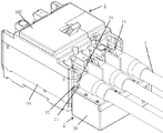
図1には、本実施形態に係る端子過熱検出装置2を回路遮断器1に取付けた状態の概略構成図を示している。図2には、端子過熱検出装置の取付方法の概略図を示している。図3には、端子過熱検出装置を示している。図4には、端子過熱検出装置の内部組立図を示している。図5には、端子過熱検出装置のスイッチ手段の組立構造を示している。図6には、端子過熱検出装置のテスト操作手段を示している。図7には、テスト操作手段の組立構造を示している。図8には、従来例における端子の接続不良を検出する構造を示している。
In FIG. 1, the schematic block diagram of the state which attached the terminal
まず、図1および図2に示す回路遮断器1の基本構造について説明を行う。図1および図2において、回路遮断器1は、外郭がモールドケースからなる回路遮断器筐体により構成されている。回路遮断器筐体は回路遮断器の内部部品を取付ける基台101と、該基台に被せられて内部部品を覆うカバー102とからなる。前記回路遮断器1の内部には、電源側の電路と負荷側の電路とを入切するために、端子12と一体化した固定接触子(図示しない)と、可動接触子(図示しない)とが配設される。また、前記固定接触子と前記可動接触子を開閉駆動させる開閉機構部(図示しない)と、電路に流れる異常電流を検出することにより前記開閉機構部に作用して該開閉機構部の引外し動作を行わせ、前記固定接触子と前記可動接触子とを開駆動させる引外し装置部(図示しない)とが設けられている。
First, the basic structure of the
前記回路遮断器1には、外部の導体と接続される前記端子12が各極の電源に対応して複数設けられており、夫々外部に露出している。
The
前記端子12には、外方から電線3が接続される。電線3の先端部には、圧着端子31がカシメにより取り付けられており、前記端子12には、該圧着端子31が端子ねじ11によってねじ締め固定される。
An electric wire 3 is connected to the terminal 12 from the outside. A
次に、回路遮断器1に取り付けられる端子過熱検出装置2について図1および図2を用いて説明を行う。端子過熱検出装置2の、端子12に接続されて端子12の熱が伝導される接続部である熱伝導端子21は、回路遮断器1の端子ねじ11を貫通させる貫通孔を有しており、電線3の圧着端子31と端子12との間に挟まれるようにして、端子ねじ11により熱伝導端子21が締付固定される。端子温度表示装置2は、取付け時に、回路遮断器1の取付面、つまり回路遮断器1の底面と端子12に接続される電線3との間に位置する。
Next, the terminal
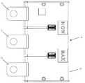
次に、端子12の異常過熱を検出する機能を有する端子過熱検出装置2の構成について図3、図4および図5を用いて説明を行う。
Next, the configuration of the terminal
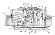
図3、図4および図5に示すとおり、端子温度表示装置2は、回路遮断器1の各極の端子12に接続されて端子12の熱が伝導される接続部である熱伝導端子21と、熱伝導端子21に固着した熱動素子22と、熱動素子22の近傍に配置され、熱動素子22の変位が伝達されるとともに応動に対応して往復変位する変位伝達部である第一の作動体23と、第一の作動体23の近傍に配置され、第一の作動体23の往復変位に対応して往復変位する同じく変位伝達部である第二の作動体24と、変位伝達部の変位が伝達されて所定の閾値を超えた場合に駆動される信号出力部であるマイクロスイッチ25と、これら熱動素子22、第一の作動体23、第二の作動体24、マイクロスイッチ25を収納する筐体26とを備えて構成される。
As shown in FIGS. 3, 4, and 5, the terminal
熱伝導端子21に固着される熱動素子22は、端子12と接続された熱伝導端子21からの熱伝導を受けて定量的に変位するバイメタルを用いて構成している。図4および図5では、熱動素子22は熱伝導端子21に対してねじ締めで固着されているが、ねじ締めに限らず、溶接やリベットによる固着でもよい。
The
第一の作動体23は、第一の作動体23を付勢する弾性部材(図示しない)により、筐体26の位置規制部261に当接するよう付勢され、熱動素子22と一定のギャップを設けた状態で配置される。
The
図5に示す通り、第二の作動体24は、マイクロスイッチ25に当接するように、弾性部材241によって付勢されている。第二の作動体24は、熱動素子22が熱伝導端子21からの熱伝導によって変位したとき、熱動素子22の変位を受けて図5に示すA方向へ回動する第一の作動体23に連動して、弾性部材241に抗して図5に示すB方向へ回動する。端子12が異常過熱したとき、即ち熱動素子22の変位の大きさが一定量を超えたとき、第二の作動体24によってマイクロスイッチ25の接点操作部が操作されることで、マイクロスイッチ25は端子12の異常過熱を知らせる信号を出力するよう操作される。
As shown in FIG. 5, the
端子12の発熱が治まれば、熱動素子22の変位が小さくなる。熱動素子22の変位が小さくなることで、第一の作動体23と第二の作動体24は、第一の作動体23を付勢する弾性部材(図示しない)や第二の作動体24を付勢する弾性部材241によって、端子12が発熱する前の位置まで回動する。端子12の異常過熱が治まったとき、即ち熱動素子22の変位の大きさが一定量以下となったとき、マイクロスイッチ25の接点操作部が第二の作動体24によって操作されることで、マイクロスイッチ25は端子12の異常過熱を知らせる信号を出力しないよう操作される。
When the heat generation at the terminal 12 is cured, the displacement of the
端子12の発熱は、熱伝導端子21を介して熱伝導する。その熱量に応じて熱動素子22が定量的に変位するため、第一の作動体23と第二の作動体24は熱動素子22の変位量に応じた回動をする。よって、端子12の発熱量と熱動素子22の変位量と第一の作動体23と第二の作動体24の回動量は相関のとれたものとなるため、端子12が異常過熱したとき、即ち熱動素子22の変位の大きさが一定量を超えたときと、端子12が異常過熱していないとき、即ち熱動素子22の変位の大きさが一定量以下であるときとで、マイクロスイッチ25の接点操作部の状態が切り替わるように構成することができる。
The heat generated at the terminal 12 is conducted through the
このような構成により、端子過熱検出装置2の熱伝導端子21を、既存の回路遮断器の端子12に、端子ねじ11で取り付けることで、回路遮断器1の改造の必要なく、端子過熱検出装置2を取付けることができる。また、熱伝導端子21に固着された熱動素子22の変位の大きさが一定量を超えたときにマイクロスイッチ25の接点操作部が操作されるように構成することで、簡単な構成で端子12の異常過熱状態を出力することができる。
With such a configuration, the terminal
なお、図4、図5および図6ではマイクロスイッチ25は第一の作動体23と第二の作動体24を介して操作される構成となっているが、これに限らず、例えば熱動素子22がマイクロスイッチ25の接点操作部に直接当接することでマイクロスイッチ25を操作する構成としてもよい。
4, 5, and 6, the
また、マイクロスイッチ25の接点操作部の操作は、本実施例では熱動素子22が変位した時に接点操作部に当接した状態から当接していない状態となる構成としたが、反対に、熱動素子22が変位した時に当接していない状態から当接する状態となる構成としてもよいことは言うまでもない。
Further, in the present embodiment, the operation of the contact operating portion of the
次に、複数の端子12を一括監視でき、最も発熱している端子12によって異常過熱を検出できる端子過熱検出装置2について図4および図5を用いて説明を行う。
Next, the terminal
図4に示す第一の作動体23は、各極の端子12にわたる形で筐体26に回動可能に固定されている。
The
このような構成により、第一の作動体23がわたっている極の端子12に固着された熱動素子22のうち、最も高い温度で変位している熱動素子22のみに第一の作動体23が連動して、第一の作動体23を付勢する弾性部材(図示しない)に抗して図5に示すA方向へ回動し、第一の作動体23によって第二の作動体24が弾性部材241に抗して図5に示すB方向へ回動することで、マイクロスイッチ25の接点操作部を操作することができる。よって第一の作動体23がわたっている複数の端子12の発熱状態を一括監視でき、最も発熱している端子12に基づいて異常過熱を検出できる。これにより、各端子12に端子過熱検出装置2を配置するよりも少ない部品点数で、各端子12の異常過熱を検出することができる。
With such a configuration, only the
なお、図4および図5では、マイクロスイッチ25は第一の作動体23と第二の作動体24を介して操作される構成となっているが、これに限らず、例えば第一の作動体23がマイクロスイッチ25の操作部251に直接当接することでマイクロスイッチ25を操作する構成としてもよい。
4 and 5, the
次に、テスト操作手段によってスイッチ手段であるマイクロスイッチ25を意図して操作することで、マイクロスイッチ25が正常に信号を出力できることをテストすることができる端子過熱検出装置2について図5、図6および図7を用いて説明を行う。
Next, the terminal
図6に示す通り、マイクロスイッチ25が配置された筐体26において、マイクロスイッチ25近傍の面にはテスト操作手段27が挿入されている。
As shown in FIG. 6, a test operation means 27 is inserted in a surface near the
図7に示す通り、テスト操作手段27の一端側は筐体26の外部に露出しており、テスト操作手段27の他端側はマイクロスイッチ25の操作手段を操作できるように筐体26の内部に向かってテスト用弾性部材271とともに挿入されている。本実施形態の場合は、テスト操作手段27の他端側は、第二の作動体24を回動させるように配設されている。
As shown in FIG. 7, one end side of the test operation means 27 is exposed to the outside of the
筐体26の外部に露出しているテスト操作手段27の一端側を操作すると、テスト操作手段27の他端側は、マイクロスイッチ25の操作部を、熱動素子22の変位の大きさが一定量を超えた場合と同じように操作させる。例えば図5、図6および図7の場合、テスト操作手段27の一端側を押すと、テスト操作手段27がテスト用弾性部材271に抗して筐体26の内部に向かって移動することで、テスト操作手段27の他端側が、第二の作動体24を図5に示すB方向に回動させるように構成される。
When one end side of the test operation means 27 exposed to the outside of the
このような構成により、テスト操作手段27を操作することで、マイクロスイッチ25の操作部を意図的に操作することができる。これにより、マイクロスイッチ25が正常に動作することを、テスト操作手段27を操作したときのマイクロスイッチ25の信号出力の有無によって確認できるため、マイクロスイッチ25のテスト動作確認が容易に可能な端子過熱検出装置2を提供できる。
With such a configuration, the operation unit of the
なお、図5、図6および図7では、テスト操作手段27を押すことで第二の作動体24を回動させる構成となっているが、これに限らず、テスト操作手段27を何らかの方法で操作することで、マイクロスイッチ25の操作部が操作される構成であればよいことは言うまでもない。例えば、テスト操作手段は押しボタン式に限らず、スライドボタン式としてもよいし、テスト操作手段27は第二の作動体24を回動させる構成に限らず、第一の作動体23を回動させる構成や、マイクロスイッチ25の操作部を直接操作する構成としてもよい。
5, 6, and 7, the
尚、本発明は、上記実施形態に限定されるものではなく、本発明の要旨を逸脱しない範囲で種々の変更が可能である。 In addition, this invention is not limited to the said embodiment, A various change is possible in the range which does not deviate from the summary of this invention.
1 回路遮断器
11 端子ねじ
12 端子
2 端子過熱検出装置
21 熱伝導端子
22 熱動素子
23 第一の作動体
24 第二の作動体
241 弾性部材
25 スイッチ手段(マイクロスイッチ)
26 筐体
261 位置規制部
27 テスト操作手段
271 テスト用弾性部材
3 電線
31 圧着端子
DESCRIPTION OF
26
Claims (3)
前記端子に接続されて該端子の熱が伝導される接続部と、
前記接続部に一端が固着されるとともに他端が前記熱の変化に応動して変位自在に配設される熱動素子と、
前記熱動素子の変位が伝達されるとともに応動に対応して往復変位する変位伝達部と、
前記変位伝達部の変位が伝達されて駆動される表示機構と、
前記変位伝達部の変位が伝達されて所定の閾値を超えた場合に駆動される信号出力部と、を備えたことを特徴とする端子過熱検出装置。
A terminal overheat detection device that is attached to a terminal of a circuit breaker and detects the temperature of the terminal,
A connecting portion connected to the terminal and conducting heat of the terminal;
A thermal element having one end fixed to the connection portion and the other end arranged to be displaceable in response to the change in heat;
A displacement transmitting portion that transmits the displacement of the thermal element and reciprocates in response to the response;
A display mechanism that is driven by transmission of displacement of the displacement transmission unit;
And a signal output unit that is driven when a displacement of the displacement transmitting unit is transmitted and exceeds a predetermined threshold value.
前記変位伝達部は夫々の前記熱動素子に共通して設けられることにより、
夫々の前記熱動素子における最大の変位が前記変位伝達部に伝達されて、
前記信号出力部を駆動することを特徴とする請求項1記載の端子過熱検出装置。
While the connection portion where the thermal element is disposed is disposed corresponding to the number of the terminals of the circuit breaker,
By providing the displacement transmission part in common to each of the thermal elements,
The maximum displacement in each of the thermal elements is transmitted to the displacement transmission unit,
The terminal overheat detection device according to claim 1, wherein the signal output unit is driven.
前記筐体の外部から操作することによって前記変位伝達部を変位させて、前記信号出力部を駆動するテスト操作部を備えたことを特徴とする請求項1又は請求項2記載の端子過熱検出装置。
While a part of the connection part is exposed to the outside, the thermodynamic element, the displacement transmission part, the display mechanism, and a substantially rectangular parallelepiped housing that houses the signal output part,
3. The terminal overheat detection device according to claim 1, further comprising a test operation unit that drives the signal output unit by displacing the displacement transmission unit by operating from the outside of the housing. .
Priority Applications (1)
| Application Number | Priority Date | Filing Date | Title |
|---|---|---|---|
| JP2016073251A JP6792343B2 (en) | 2016-03-31 | 2016-03-31 | Terminal overheat detector |
Applications Claiming Priority (1)
| Application Number | Priority Date | Filing Date | Title |
|---|---|---|---|
| JP2016073251A JP6792343B2 (en) | 2016-03-31 | 2016-03-31 | Terminal overheat detector |
Related Child Applications (3)
| Application Number | Title | Priority Date | Filing Date |
|---|---|---|---|
| JP2020077987A Division JP7070940B2 (en) | 2020-04-27 | 2020-04-27 | Terminal overheat detector |
| JP2020077989A Division JP7070942B2 (en) | 2020-04-27 | 2020-04-27 | Terminal overheat detector |
| JP2020077988A Division JP7070941B2 (en) | 2020-04-27 | 2020-04-27 | Terminal overheat detector |
Publications (2)
| Publication Number | Publication Date |
|---|---|
| JP2017183244A true JP2017183244A (en) | 2017-10-05 |
| JP6792343B2 JP6792343B2 (en) | 2020-11-25 |
Family
ID=60008706
Family Applications (1)
| Application Number | Title | Priority Date | Filing Date |
|---|---|---|---|
| JP2016073251A Active JP6792343B2 (en) | 2016-03-31 | 2016-03-31 | Terminal overheat detector |
Country Status (1)
| Country | Link |
|---|---|
| JP (1) | JP6792343B2 (en) |
Citations (6)
| Publication number | Priority date | Publication date | Assignee | Title |
|---|---|---|---|---|
| JPS5625156Y2 (en) * | 1976-01-29 | 1981-06-13 | ||
| JPS6076854U (en) * | 1983-11-01 | 1985-05-29 | 三菱電機株式会社 | circuit break |
| JPH0668779A (en) * | 1992-08-19 | 1994-03-11 | Tempearl Ind Co Ltd | Earthing preventive circuit breaker |
| JPH07151809A (en) * | 1993-11-26 | 1995-06-16 | Fujitsu Syst Constr Kk | Detection of incompletely screwed part |
| JP2012216378A (en) * | 2011-03-31 | 2012-11-08 | Tempearl Ind Co Ltd | Circuit breaker with abnormal overheat detection structure |
| CN204857614U (en) * | 2015-08-24 | 2015-12-09 | 常熟开关制造有限公司(原常熟开关厂) | Moulded case circuit breaker with heat overload alarming function |
-
2016
- 2016-03-31 JP JP2016073251A patent/JP6792343B2/en active Active
Patent Citations (6)
| Publication number | Priority date | Publication date | Assignee | Title |
|---|---|---|---|---|
| JPS5625156Y2 (en) * | 1976-01-29 | 1981-06-13 | ||
| JPS6076854U (en) * | 1983-11-01 | 1985-05-29 | 三菱電機株式会社 | circuit break |
| JPH0668779A (en) * | 1992-08-19 | 1994-03-11 | Tempearl Ind Co Ltd | Earthing preventive circuit breaker |
| JPH07151809A (en) * | 1993-11-26 | 1995-06-16 | Fujitsu Syst Constr Kk | Detection of incompletely screwed part |
| JP2012216378A (en) * | 2011-03-31 | 2012-11-08 | Tempearl Ind Co Ltd | Circuit breaker with abnormal overheat detection structure |
| CN204857614U (en) * | 2015-08-24 | 2015-12-09 | 常熟开关制造有限公司(原常熟开关厂) | Moulded case circuit breaker with heat overload alarming function |
Also Published As
| Publication number | Publication date |
|---|---|
| JP6792343B2 (en) | 2020-11-25 |
Similar Documents
| Publication | Publication Date | Title |
|---|---|---|
| US8605402B2 (en) | Heat sensor responsive to electrical overloads | |
| FI82997B (en) | KRETSAVBRYTARE. | |
| CA2845781C (en) | Device for thermal monitoring of the terminals of an electrical connection device | |
| US8159803B2 (en) | Heat actuated interrupter receptacle | |
| US20100073839A1 (en) | Systems and Methods for Detecting Unsafe Thermal Conditions in Wiring Devices | |
| KR102345251B1 (en) | Earth leakage breaker | |
| KR101771551B1 (en) | terminal block for switch panel and dstribution panel | |
| US20190097412A1 (en) | Leakage current detection and protection device for power cord | |
| CN102592884A (en) | High-temperature-resistant thermal protector | |
| KR101141915B1 (en) | Surge protect device having overheating prevention function based surge suppression device | |
| JP7070942B2 (en) | Terminal overheat detector | |
| JP6846064B2 (en) | Circuit breaker with terminal temperature display function | |
| JP6650207B2 (en) | Terminal connection failure detection device | |
| JP5808038B2 (en) | Circuit breaker with abnormal overheat detection structure | |
| US6466424B1 (en) | Circuit protective device with temperature sensing | |
| KR20090130992A (en) | The electrical device with sensor for temperature | |
| JP7070941B2 (en) | Terminal overheat detector | |
| JP7070940B2 (en) | Terminal overheat detector | |
| JP2017183244A (en) | Terminal overheat detector | |
| JP7008982B2 (en) | Circuit breaker with terminal temperature display function | |
| JP6924502B2 (en) | Terminal connection failure detector | |
| RU2414765C2 (en) | Air circuit breaker with temperature sensor | |
| JP7229594B2 (en) | Circuit breaker with terminal temperature display function | |
| JP6652874B2 (en) | Circuit breaker with terminal temperature display function | |
| JPS628419A (en) | Circuit breaker with overheating preventor |
Legal Events
| Date | Code | Title | Description |
|---|---|---|---|
| A621 | Written request for application examination |
Free format text: JAPANESE INTERMEDIATE CODE: A621 Effective date: 20181010 |
|
| A977 | Report on retrieval |
Free format text: JAPANESE INTERMEDIATE CODE: A971007 Effective date: 20190813 |
|
| A131 | Notification of reasons for refusal |
Free format text: JAPANESE INTERMEDIATE CODE: A131 Effective date: 20190910 |
|
| A521 | Request for written amendment filed |
Free format text: JAPANESE INTERMEDIATE CODE: A523 Effective date: 20191111 |
|
| A131 | Notification of reasons for refusal |
Free format text: JAPANESE INTERMEDIATE CODE: A131 Effective date: 20200218 |
|
| A601 | Written request for extension of time |
Free format text: JAPANESE INTERMEDIATE CODE: A601 Effective date: 20200420 |
|
| A521 | Request for written amendment filed |
Free format text: JAPANESE INTERMEDIATE CODE: A523 Effective date: 20200427 |
|
| TRDD | Decision of grant or rejection written | ||
| A01 | Written decision to grant a patent or to grant a registration (utility model) |
Free format text: JAPANESE INTERMEDIATE CODE: A01 Effective date: 20201006 |
|
| A61 | First payment of annual fees (during grant procedure) |
Free format text: JAPANESE INTERMEDIATE CODE: A61 Effective date: 20201106 |
|
| R150 | Certificate of patent or registration of utility model |
Ref document number: 6792343 Country of ref document: JP Free format text: JAPANESE INTERMEDIATE CODE: R150 |
|
| R250 | Receipt of annual fees |
Free format text: JAPANESE INTERMEDIATE CODE: R250 |