JP2017182194A - Control method for authentication device, and control method for printer - Google Patents

Control method for authentication device, and control method for printer Download PDF

Info

Publication number
JP2017182194A
JP2017182194A JP2016064328A JP2016064328A JP2017182194A JP 2017182194 A JP2017182194 A JP 2017182194A JP 2016064328 A JP2016064328 A JP 2016064328A JP 2016064328 A JP2016064328 A JP 2016064328A JP 2017182194 A JP2017182194 A JP 2017182194A
Authority
JP
Japan
Prior art keywords
medium
reading
card
information
wireless communication
Prior art date
Legal status (The legal status is an assumption and is not a legal conclusion. Google has not performed a legal analysis and makes no representation as to the accuracy of the status listed.)
Pending
Application number
JP2016064328A
Other languages
Japanese (ja)
Inventor
野口 昭彦
Akihiko Noguchi
昭彦 野口
Current Assignee (The listed assignees may be inaccurate. Google has not performed a legal analysis and makes no representation or warranty as to the accuracy of the list.)
Seiko Epson Corp
Original Assignee
Seiko Epson Corp
Priority date (The priority date is an assumption and is not a legal conclusion. Google has not performed a legal analysis and makes no representation as to the accuracy of the date listed.)
Filing date
Publication date
Application filed by Seiko Epson Corp filed Critical Seiko Epson Corp
Priority to JP2016064328A priority Critical patent/JP2017182194A/en
Priority to CN201710116919.0A priority patent/CN107234882B/en
Publication of JP2017182194A publication Critical patent/JP2017182194A/en
Pending legal-status Critical Current

Links

Images

Abstract

PROBLEM TO BE SOLVED: To provide a control method for an authentication device capable of excluding human intermediation in reading of recorded information inside a medium (for example, an ID card) and in reading of recorded information on a medium surface (as a result, a security aspect can be improved).SOLUTION: A control method in an authentication device including: a transportation mechanism transporting a medium; a radio communication section reading information recorded inside the medium by radio; and an optical reading section optically reading information recorded on a surface of the medium, performs reading by the radio communication section in a transportation stop state of the medium after reading execution by the optical reading section.SELECTED DRAWING: Figure 11

Description

本発明は、認証装置の制御方法、及び印刷装置の制御方法に関し、特に、人が介在することなく、媒体(例えば、IDカード)内部の記録情報の読み取りや媒体表面の記録情報の読み取りができる(その結果、セキュリティ面を向上できる)認証装置の制御方法、及び印刷装置の制御方法に関する。   The present invention relates to a method for controlling an authentication apparatus and a method for controlling a printing apparatus, and in particular, can read recorded information inside a medium (for example, an ID card) or read recorded information on the surface of a medium without human intervention. The present invention relates to a method for controlling an authentication apparatus (which can improve security), and a method for controlling a printing apparatus.

従来、IDカードを無線で読み取るカードリーダを備えた装置(例えば、特許文献1参照)や文字情報を光学的に読み取る光学読取部を備えた装置(例えば、特許文献2参照)が知られている。   2. Description of the Related Art Conventionally, an apparatus including a card reader that wirelessly reads an ID card (for example, see Patent Document 1) and an apparatus including an optical reading unit that optically reads character information (for example, see Patent Document 2) are known. .

特開2016−015033号公報JP, 2006-015033, A 特開平5−258100号公報JP-A-5-258100

しかしながら、カードリーダと光学読取部とを認証に用いる場合、上記従来技術のように、カードリーダと光学読取部とを物理的に独立した別々の装置として構成し、カードリーダによるIDカード内部の記録情報の読み取りや光学読取部によるIDカード表面の記録情報の読み取りを人が介在して行う場合、IDカード書込み内容の偽装や身分詐称といった不正を行う余地が残り、セキュリティ面で課題がある。   However, when the card reader and the optical reading unit are used for authentication, the card reader and the optical reading unit are configured as separate devices that are physically independent as in the above-described prior art, and recording inside the ID card by the card reader is performed. When reading information or reading information recorded on the surface of an ID card by an optical reader is performed by a person, there remains room for fraud such as disguise of ID card writing contents and identity misrepresentation, and there is a problem in terms of security.

本発明は、上記事情に鑑みてなされたものであり、媒体(例えば、IDカード)内部の記録情報の読み取りや媒体表面の記録情報の読み取りにおいて、人が介在するのを排除できる(その結果、セキュリティ面を向上できる)認証装置の制御方法を提供することを目的とする。   The present invention has been made in view of the above circumstances, and can eliminate human intervention in reading recorded information inside a medium (for example, an ID card) and reading recorded information on the surface of the medium (as a result, It is an object of the present invention to provide a method for controlling an authentication device that can improve security.

上記目的を達成するために、本発明の一つの側面は、媒体を搬送する搬送機構と、前記媒体の内部に記録された情報を無線で読み取る無線通信部と、前記媒体の表面に記録された情報を光学的に読み取る光学読取部と、を有する認証装置における制御方法であって、前記光学読取部による読取実行前に、前記無線通信部による読み取りを、前記媒体の搬送停止状態で行うことを特徴とする。   In order to achieve the above object, one aspect of the present invention is recorded on a surface of a medium, a conveyance mechanism that conveys the medium, a wireless communication unit that wirelessly reads information recorded in the medium, and A control method in an authentication apparatus having an optical reading unit for optically reading information, wherein reading by the wireless communication unit is performed in a state where conveyance of the medium is stopped before reading by the optical reading unit. Features.

この側面によれば、媒体(例えば、IDカード)内部の記録情報の読み取りや媒体表面の記録情報の読み取りにおいて、人が介在するのを排除できる(その結果、セキュリティ面を向上できる)認証装置の制御方法を提供できる。   According to this aspect, it is possible to eliminate the presence of a person in reading recorded information inside a medium (for example, an ID card) or reading recorded information on the surface of the medium (as a result, security can be improved). A control method can be provided.

これは、媒体内部の記録情報の読み取りや媒体表面の記録情報の読み取りを、搬送機構によって媒体を搬送することで実現できるため、媒体内部の記録情報の読み取りや媒体表面の記録情報の読み取りに際して、人が介在するのを排除できることによるものである。   This can be realized by reading the recording information inside the medium and reading the recording information on the medium surface by transporting the medium by the transport mechanism. This is because human intervention can be eliminated.

また、この側面によれば、媒体から、その内部に記録された情報を精度よく読み取ることができる。   Further, according to this aspect, information recorded in the medium can be accurately read from the medium.

これは、無線通信部は、搬送状態の媒体からではなく、搬送停止状態の媒体から、その内部に記録された情報を読み取ることによるものである。   This is because the wireless communication unit reads the information recorded therein not from the transported medium but from the transport stopped medium.

上記目的を達成するために、本発明の別の側面は、媒体を搬送する搬送機構と、前記媒体の内部に記録された情報を無線で読み取る無線通信部と、前記媒体の表面に記録された情報を光学的に読み取る光学読取部と、を有する認証装置における制御方法であって、前記光学読取部による読取実行後に、前記無線通信部による読み取りを、前記媒体の搬送停止状態で行うことを特徴とする。   In order to achieve the above object, another aspect of the present invention provides a transport mechanism that transports a medium, a wireless communication unit that wirelessly reads information recorded in the medium, and a surface recorded on the surface of the medium. A control method in an authentication apparatus having an optical reading unit that optically reads information, wherein after the reading by the optical reading unit, reading by the wireless communication unit is performed in a state where conveyance of the medium is stopped. And

この側面によれば、媒体(例えば、IDカード)内部の記録情報の読み取りや媒体表面の記録情報の読み取りにおいて、人が介在するのを排除できる(その結果、セキュリティ面を向上できる)認証装置の制御方法を提供できる。   According to this aspect, it is possible to eliminate the presence of a person in reading recorded information inside a medium (for example, an ID card) or reading recorded information on the surface of the medium (as a result, security can be improved). A control method can be provided.

これは、媒体内部の記録情報の読み取りや媒体表面の記録情報の読み取りを、搬送機構によって媒体を搬送することで実現できるため、媒体内部の記録情報の読み取りや媒体表面の記録情報の読み取りに際して、人が介在するのを排除できることによるものである。   This can be realized by reading the recording information inside the medium and reading the recording information on the medium surface by transporting the medium by the transport mechanism. This is because human intervention can be eliminated.

また、この側面によれば、媒体から、その内部に記録された情報を精度よく読み取ることができる。   Further, according to this aspect, information recorded in the medium can be accurately read from the medium.

これは、無線通信部は、搬送状態の媒体からではなく、搬送停止状態の媒体から、その内部に記録された情報を読み取ることによるものである。   This is because the wireless communication unit reads the information recorded therein not from the transported medium but from the transport stopped medium.

上記目的を達成するために、本発明のさらに別の側面は、媒体を搬送する搬送機構と、前記媒体の内部に記録された情報を無線で読み取る無線通信部と、前記媒体の表面に記録された情報を光学的に読み取る光学読取部と、を有する認証装置における制御方法であって、前記光学読取部による読み取り実行中に、前記無線通信部による読み取りを実行することを特徴とする。   In order to achieve the above object, still another aspect of the present invention provides a transport mechanism that transports a medium, a wireless communication unit that wirelessly reads information recorded in the medium, and a surface recorded on the surface of the medium. A control method in an authentication apparatus having an optical reading unit that optically reads the information, wherein the reading by the wireless communication unit is executed during the reading by the optical reading unit.

この側面によれば、媒体(例えば、IDカード)内部の記録情報の読み取りや媒体表面の記録情報の読み取りにおいて、人が介在するのを排除できる(その結果、セキュリティ面を向上できる)認証装置の制御方法を提供できる。   According to this aspect, it is possible to eliminate the presence of a person in reading recorded information inside a medium (for example, an ID card) or reading recorded information on the surface of the medium (as a result, security can be improved). A control method can be provided.

これは、媒体内部の記録情報の読み取りや媒体表面の記録情報の読み取りを、搬送機構によって媒体を搬送することで実現できるため、媒体内部の記録情報の読み取りや媒体表面の記録情報の読み取りに際して、人が介在するのを排除できることによるものである。   This can be realized by reading the recording information inside the medium and reading the recording information on the medium surface by transporting the medium by the transport mechanism. This is because human intervention can be eliminated.

また、この側面によれば、媒体から、その内部に記録された情報を迅速に読み取ることができる。   Further, according to this aspect, information recorded in the medium can be quickly read from the medium.

これは、無線通信部は、搬送停止状態の媒体からではなく、搬送状態(搬送中)の媒体から、その内部に記録された情報を読み取ることによるものである。   This is because the wireless communication unit reads the information recorded in the medium from the medium in the conveyance state (during conveyance), not from the medium in the conveyance stop state.

上記目的を達成するために、本発明のさらに別の側面は、媒体を搬送する搬送機構と、前記媒体の内部に記録された情報を無線で読み取る無線通信部と、前記媒体の表面に記録された情報を光学的に読み取る光学読取部と、を有する認証装置における制御方法であって、前記光学読取部による読み取り実行後の前記媒体排出中に、前記無線通信部による読み取りを実行することを特徴とする。   In order to achieve the above object, still another aspect of the present invention provides a transport mechanism that transports a medium, a wireless communication unit that wirelessly reads information recorded in the medium, and a surface recorded on the surface of the medium. And an optical reading unit that optically reads the read information, wherein the wireless communication unit performs reading while the medium is being discharged after the optical reading unit performs reading. And

この側面によれば、媒体(例えば、IDカード)内部の記録情報の読み取りや媒体表面の記録情報の読み取りにおいて、人が介在するのを排除できる(その結果、セキュリティ面を向上できる)認証装置の制御方法を提供できる。   According to this aspect, it is possible to eliminate the presence of a person in reading recorded information inside a medium (for example, an ID card) or reading recorded information on the surface of the medium (as a result, security can be improved). A control method can be provided.

これは、媒体内部の記録情報の読み取りや媒体表面の記録情報の読み取りを、搬送機構によって媒体を搬送することで実現できるため、媒体内部の記録情報の読み取りや媒体表面の記録情報の読み取りに際して、人が介在するのを排除できることによるものである。   This can be realized by reading the recording information inside the medium and reading the recording information on the medium surface by transporting the medium by the transport mechanism. This is because human intervention can be eliminated.

また、この側面によれば、媒体から、その内部に記録された情報を迅速に読み取ることができる。   Further, according to this aspect, information recorded in the medium can be quickly read from the medium.

これは、無線通信部は、搬送停止状態の媒体からではなく、搬送状態(搬送中)の媒体から、その内部に記録された情報を読み取ることによるものである。   This is because the wireless communication unit reads the information recorded in the medium from the medium in the conveyance state (during conveyance), not from the medium in the conveyance stop state.

上記目的を達成するために、本発明のさらに別の側面は、媒体を搬送する搬送機構と、前記媒体の内部に記録された情報を無線で読み取る無線通信部と、前記媒体の表面に記録された情報を光学的に読み取る光学読取部と、を有する印刷装置における制御方法であって、前記光学読取部による読取実行前に、前記無線通信部による読み取りを、前記媒体の搬送停止状態で行うことを特徴とする。   In order to achieve the above object, still another aspect of the present invention provides a transport mechanism that transports a medium, a wireless communication unit that wirelessly reads information recorded in the medium, and a surface recorded on the surface of the medium. A control method in a printing apparatus having an optical reading unit that optically reads the read information, wherein reading by the wireless communication unit is performed in a state where conveyance of the medium is stopped before reading by the optical reading unit. It is characterized by.

この側面によれば、媒体(例えば、IDカード)内部の記録情報の読み取りや媒体表面の記録情報の読み取りにおいて、人が介在するのを排除できる(その結果、セキュリティ面を向上できる)印刷装置の制御方法を提供できる。   According to this aspect, it is possible to eliminate the intervention of a person in reading recorded information inside a medium (for example, an ID card) or reading recorded information on the surface of the medium (as a result, security can be improved). A control method can be provided.

これは、媒体内部の記録情報の読み取りや媒体表面の記録情報の読み取りを、搬送機構によって媒体を搬送することで実現できるため、媒体内部の記録情報の読み取りや媒体表面の記録情報の読み取りに際して、人が介在するのを排除できることによるものである。   This can be realized by reading the recording information inside the medium and reading the recording information on the medium surface by transporting the medium by the transport mechanism. This is because human intervention can be eliminated.

また、この側面によれば、媒体から、その内部に記録された情報を精度よく読み取ることができる。   Further, according to this aspect, information recorded in the medium can be accurately read from the medium.

これは、無線通信部は、搬送状態の媒体からではなく、搬送停止状態の媒体から、その内部に記録された情報を読み取ることによるものである。   This is because the wireless communication unit reads the information recorded therein not from the transported medium but from the transport stopped medium.

実施形態におけるドットインパクトプリンターの外観斜視図である。1 is an external perspective view of a dot impact printer in an embodiment. プリンター本体を示す斜視図である。FIG. 2 is a perspective view showing a printer body. プリンター本体の側断面図である。FIG. 3 is a side sectional view of the printer body. 磁気データ読取部の構成を示す斜視図である。It is a perspective view which shows the structure of a magnetic data reading part. ドットインパクトプリンターの機能的構成を示すブロック図である。It is a block diagram which shows the functional structure of a dot impact printer. ドットインパクトプリンターの動作を示すフローチャートである。It is a flowchart which shows operation | movement of a dot impact printer. 小切手に印刷されているMICR情報の一例を示す図である。It is a figure which shows an example of the MICR information printed on the check. 認証機能付きドットインパクトプリンター10A(プリンター本体11)の外観斜視図である。1 is an external perspective view of a dot impact printer 10A (printer body 11) with an authentication function. FIG. 認証機能付きドットインパクトプリンター10Aの側断面図である。It is a sectional side view of dot impact printer 10A with an authentication function. 認証機能付きドットインパクトプリンター10Aの機能的構成を示すブロック図である。It is a block diagram which shows the functional structure of 10 A of dot impact printers with an authentication function. 認証機能付きドットインパクトプリンター10Aの動作例1(制御方法1)である認証処理について説明するフローチャートである。It is a flowchart explaining the authentication process which is the operation example 1 (control method 1) of the dot impact printer 10A with an authentication function. 認証機能付きドットインパクトプリンター10Aの動作例2(制御方法2)である認証処理について説明するフローチャートである。It is a flowchart explaining the authentication process which is the operation example 2 (control method 2) of 10 A of dot impact printers with an authentication function. 認証機能付きドットインパクトプリンター10Aの動作例3(制御方法3)である認証処理について説明するフローチャートである。It is a flowchart explaining the authentication process which is the operation example 3 (control method 3) of 10 A of dot impact printers with an authentication function. 認証機能付きドットインパクトプリンター10Aの動作例4(制御方法4)である認証処理について説明するフローチャートである。It is a flowchart explaining the authentication process which is the operation example 4 (control method 4) of 10 A of dot impact printers with an authentication function.

以下、本発明の実施形態について図面を参照して説明する。   Embodiments of the present invention will be described below with reference to the drawings.

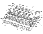
図1は、本実施形態に係る記録装置としてのドットインパクトプリンターの外観を示す正面斜視図である。図2は、プリンター本体11を示す外観斜視図である。図3は、図1のドットインパクトプリンター10を示す側断面図である。   FIG. 1 is a front perspective view showing an appearance of a dot impact printer as a recording apparatus according to the present embodiment. FIG. 2 is an external perspective view showing the printer main body 11. FIG. 3 is a side sectional view showing the dot impact printer 10 of FIG.

図1に示す記録装置としてのドットインパクトプリンター10は、記録ヘッド18(図2、図3参照)が備える複数の記録ワイヤーを、リボンカートリッジ(図示略)から繰り出したインクリボン(図示略)を介して記録媒体Sに押し付け、この記録媒体Sの記録面上にドットを形成することにより、文字を含む画像を記録するものである。   A dot impact printer 10 as a recording apparatus shown in FIG. 1 includes a plurality of recording wires provided in a recording head 18 (see FIGS. 2 and 3) via an ink ribbon (not shown) that is fed out from a ribbon cartridge (not shown). Then, it is pressed against the recording medium S, and dots are formed on the recording surface of the recording medium S, whereby an image including characters is recorded.

ドットインパクトプリンター10で使用可能な記録媒体Sとしては、所定長さに切断されたカット媒体と、複数枚が連接された連続紙とがある。カット媒体としては、例えば単票紙や単票複写紙などの他、通帳や葉書、封筒などがあり、連続紙には連続複写紙を含む。   Examples of the recording medium S that can be used in the dot impact printer 10 include a cut medium cut to a predetermined length and a continuous sheet in which a plurality of sheets are connected. As the cut medium, for example, there are a passbook, a postcard, an envelope, and the like in addition to a cut paper and a cut copy paper, and the continuous paper includes continuous copy paper.

本実施形態では、ドットインパクトプリンター10によって図1に示す記録媒体Sに画像を記録する場合を例に挙げて説明する。記録媒体Sは、金融機関等が発行する小切手または手形(以下、総称して小切手という)である。この小切手は、磁気インクによってMICR(Magnetic Ink Character Recognition)情報MSが一部に印刷された単票紙である。   In the present embodiment, a case where an image is recorded on the recording medium S shown in FIG. 1 by the dot impact printer 10 will be described as an example. The recording medium S is a check or bill (hereinafter collectively referred to as a check) issued by a financial institution or the like. This check is a cut sheet on which MICR (Magnetic Ink Character Recognition) information MS is partially printed with magnetic ink.

また、ドットインパクトプリンター10では、記録媒体Sとして、小切手だけではなく通帳も用いることができる。ここでいう通帳とは、複数枚の記録用紙が綴じられた冊子形態となっており、この冊子を開いた内側の面が記録面となっている。さらに、通帳の裏表紙に相当する面の後部には、磁気ストライプが設けられている。この磁気ストライプには磁気的に各種情報を記録し、読み取ることが可能であり、通常、記録された情報は、目視による判別を含む光学的な判別はできない。   In the dot impact printer 10, not only a check but also a passbook can be used as the recording medium S. The passbook here is in the form of a booklet in which a plurality of recording sheets are bound, and the inner surface of the booklet is the recording surface. Further, a magnetic stripe is provided at the rear of the surface corresponding to the back cover of the passbook. Various information can be magnetically recorded and read on the magnetic stripe. Normally, the recorded information cannot be optically discriminated including visual discrimination.

なお、以下の説明において、記録媒体Sの4辺のうち、ドットインパクトプリンター10へ向かって差し込まれる側の辺を先端とし、この先端と対向する側の辺を後端とする。   In the following description, of the four sides of the recording medium S, the side that is inserted toward the dot impact printer 10 is the leading end, and the side that faces the leading end is the trailing end.

ドットインパクトプリンター10は、図1に示すように、外装体としての上部カバー12、上部ケース13及び下部ケース14を備えており、上部ケース13及び下部ケース14の前面には、記録媒体Sを挿入あるいは排出する手差口15が開口している。この手差口15が開口した側、すなわち図3中の左側をフロント(前)側とし、図3中の右側をリア(後)側とする。   As shown in FIG. 1, the dot impact printer 10 includes an upper cover 12, an upper case 13, and a lower case 14 as exterior bodies, and a recording medium S is inserted in front of the upper case 13 and the lower case 14. Or the manual feed port 15 which discharges is opening. The side where the manual feed opening 15 is opened, that is, the left side in FIG. 3 is the front (front) side, and the right side in FIG. 3 is the rear (rear) side.

ドットインパクトプリンター10は、図2に示すように、上部カバー12、上部ケース13及び下部ケース14に覆われるプリンター本体11を有している。上部カバー12、上部ケース13及び下部ケース14が本発明の筐体を構成する。このプリンター本体11は、下本体部11Aと、この下本体部11Aの後端部に軸11Cで支持される上本体部(図示略)とを備え、下本体部11Aは、上部ケース13及び下部ケース14(図1)に収納されると共に、上本体部は、上部カバー12(図1)に固定されている。この上部カバー12を開いたときに、上本体部が軸11Cを中心に回動し、プリンター本体11内部が露出することとなる。   As shown in FIG. 2, the dot impact printer 10 includes a printer main body 11 covered with an upper cover 12, an upper case 13, and a lower case 14. The upper cover 12, the upper case 13, and the lower case 14 constitute a housing of the present invention. The printer main body 11 includes a lower main body portion 11A and an upper main body portion (not shown) supported by a shaft 11C at a rear end portion of the lower main body portion 11A. The lower main body portion 11A includes an upper case 13 and a lower portion. While being accommodated in the case 14 (FIG. 1), the upper main body is fixed to the upper cover 12 (FIG. 1). When the upper cover 12 is opened, the upper main body rotates about the shaft 11C, and the inside of the printer main body 11 is exposed.

図2及び図3に示すように、プリンター本体11は、ベースフレーム16、右サイドフレーム17A及び左サイドフレーム17Bを備えた本体フレームと、記録ヘッド18及びキャリッジ19を備えた記録機構部20と、プラテン21、第1駆動ローラー22A、第1従動ローラー22B、第2駆動ローラー23A、第2従動ローラー23B、第3駆動ローラー124A、第3従動ローラー124B、前方媒体案内24、後方媒体案内25、媒体搬送モーター26及び駆動輪列部27を備えた媒体搬送機構100と、記録媒体S(又は後述のIDカードS1)を整列させる整列板28と、記録媒体Sに設けられたMICR情報MSの読み取りを行う磁気ヘッド34(請求項中の「磁気読取部」に対応)を備えた磁気データ読書部29と、MICR情報MSの読み取りを含む磁気情報処理の実行時に、記録媒体Sの浮き上がりを抑制すべく、記録媒体S上から押える媒体押え部30と、を有している。   2 and 3, the printer main body 11 includes a main body frame including a base frame 16, a right side frame 17A, and a left side frame 17B, a recording mechanism section 20 including a recording head 18 and a carriage 19, and Platen 21, first driving roller 22A, first driven roller 22B, second driving roller 23A, second driven roller 23B, third driving roller 124A, third driven roller 124B, front medium guide 24, rear medium guide 25, medium The medium transport mechanism 100 including the transport motor 26 and the drive wheel train 27, the alignment plate 28 for aligning the recording medium S (or ID card S1 described later), and the MICR information MS provided on the recording medium S are read. A magnetic data reading unit 29 having a magnetic head 34 (corresponding to the “magnetic reading unit” in the claims), and MI When the magnetic information processing execution including reading the R information MS, to suppress the floating of the recording medium S, has a media pressure unit 30 that presses from the recording medium S, a.

ベースフレーム16の略両端部には、右サイドフレーム17A及び左サイドフレーム17Bが立設して固定される。これら両サイドフレーム17A、17Bの間には、キャリッジガイド軸31が架け渡されると共に、両サイドフレーム17A、17B間に平坦面形状の前方媒体案内24及び後方媒体案内25が固定して設けられる。これらの前方媒体案内24と後方媒体案内25との間に、平面形状のプラテン21が配置される。このプラテン21の上方には、プラテン21に対向するように記録ヘッド18が配置されている。   At substantially both ends of the base frame 16, a right side frame 17A and a left side frame 17B are erected and fixed. A carriage guide shaft 31 is bridged between the side frames 17A and 17B, and a flat medium front medium guide 24 and a rear medium guide 25 are fixed between the side frames 17A and 17B. A planar platen 21 is arranged between the front medium guide 24 and the rear medium guide 25. A recording head 18 is arranged above the platen 21 so as to face the platen 21.

キャリッジ19は、キャリッジガイド軸31に摺動自在に挿通され、当該キャリッジ19を駆動するキャリッジ駆動モーター56(図5)の正転又は逆転により、タイミングベルト(図示略)を介して駆動され、キャリッジガイド軸31に案内されて往復移動される。キャリッジ19の移動方向は、図中符号Xで示す方向、すなわち、キャリッジガイド軸31の軸方向及びプラテン21の長手方向と一致する主走査方向である。また、キャリッジ19の移動(走査)範囲は、一対のサイドフレーム17A、17Bの間である。なお、キャリッジ19の主走査方向Xに直交する方向、すなわち図中符号Yで示す方向を、副走査方向とする。   The carriage 19 is slidably inserted into the carriage guide shaft 31, and is driven via a timing belt (not shown) by forward or reverse rotation of a carriage drive motor 56 (FIG. 5) that drives the carriage 19. It is guided by the guide shaft 31 and reciprocated. The movement direction of the carriage 19 is the main scanning direction that coincides with the direction indicated by the symbol X in the drawing, that is, the axial direction of the carriage guide shaft 31 and the longitudinal direction of the platen 21. The range of movement (scanning) of the carriage 19 is between the pair of side frames 17A and 17B. Note that a direction orthogonal to the main scanning direction X of the carriage 19, that is, a direction indicated by a symbol Y in the figure is a sub-scanning direction.

キャリッジ19に搭載される記録ヘッド18は、キャリッジ19と共に主走査方向に走行される間に、その先端面においてプラテン21に対向するワイヤー突出部(図示略)から記録ワイヤーを突出させてインクリボンに打ち当て、このインクリボンのインクを、プラテン21と記録ヘッド18との間に搬送される記録媒体Sに付着させて、記録媒体Sに文字を含む画像を記録する。このインクリボンは、上記の本体フレーム又はキャリッジ19に装着されるリボンカートリッジ(図示略)内に折り畳まれて収納され、キャリッジ19の走査に伴って繰り出される。   While the recording head 18 mounted on the carriage 19 travels in the main scanning direction together with the carriage 19, the recording wire protrudes from a wire protruding portion (not shown) facing the platen 21 at the front end surface thereof to form an ink ribbon. The ink of the ink ribbon is applied to the recording medium S transported between the platen 21 and the recording head 18 to record an image including characters on the recording medium S. The ink ribbon is folded and stored in a ribbon cartridge (not shown) mounted on the main body frame or the carriage 19 and is fed out as the carriage 19 is scanned.

プラテン21は、キャリッジ19の走行方向に延在して平面形状に形成され、その両端が、付勢ばね49により記録ヘッド18に向けて付勢されると共に、弾性支持されている。付勢ばね49は圧縮コイルばねであり、この付勢ばね49の付勢力により、記録ヘッド18の記録動作時における記録ワイヤーの突出力が支持される。また、プラテン21は、記録媒体Sの搬送中にこの記録媒体Sの厚さが変化した場合、又はプリンター本体11に厚さの異なる記録媒体Sが搬入された場合に、付勢ばね49の付勢力に抗して、記録ヘッド18の先端により押圧されて記録ヘッド18から離れる方向に移動する。これにより、記録媒体の厚さにかかわらず、記録ヘッド18の先端と記録媒体Sの記録面との間のギャップが一定に確保される。   The platen 21 extends in the traveling direction of the carriage 19 and is formed in a planar shape. Both ends of the platen 21 are urged toward the recording head 18 by an urging spring 49 and are elastically supported. The urging spring 49 is a compression coil spring, and the urging force of the urging spring 49 supports the projecting output of the recording wire during the recording operation of the recording head 18. Further, the platen 21 is provided with an urging spring 49 when the thickness of the recording medium S changes during conveyance of the recording medium S or when the recording medium S having a different thickness is loaded into the printer main body 11. The head is pressed by the tip of the recording head 18 against the force and moves away from the recording head 18. Thus, a constant gap is ensured between the tip of the recording head 18 and the recording surface of the recording medium S regardless of the thickness of the recording medium.

媒体搬送機構100は、第1駆動ローラー22A、第1従動ローラー22Bが、プラテン21及び記録ヘッド18に対してプリンター本体11のフロント側に配置され、第2駆動ローラー23A、第2従動ローラー23Bが、プラテン21及び記録ヘッド18に対してプリンター本体11のリア側及び裏面スキャナー112(請求項中の「光学読取部」に対応)のフロント側に配置され、第3駆動ローラー124A、第3従動ローラー124Bが、裏面スキャナー112のリア側に配置されて構成される。第1駆動ローラー22Aと第1従動ローラー22Bとは、上下方向に配置されて対をなし、第2駆動ローラー23Aと第2従動ローラー23Bとは、上下方向に配置されて対をなし、第3駆動ローラー124Aと第3従動ローラー124Bとは、上下方向に配置されて対をなす。   In the medium transport mechanism 100, the first drive roller 22A and the first driven roller 22B are disposed on the front side of the printer main body 11 with respect to the platen 21 and the recording head 18, and the second drive roller 23A and the second driven roller 23B are provided. The third drive roller 124A and the third driven roller are disposed on the rear side of the printer main body 11 and the front side of the back surface scanner 112 (corresponding to “optical reading unit” in the claims) with respect to the platen 21 and the recording head 18. 124B is arranged on the rear side of the back scanner 112. The first driving roller 22A and the first driven roller 22B are arranged in a vertical direction to make a pair, and the second driving roller 23A and the second driven roller 23B are arranged in a vertical direction to make a pair, a third The driving roller 124A and the third driven roller 124B are arranged in the vertical direction to make a pair.

第1駆動ローラー22A、第2駆動ローラー23A及び第3駆動ローラー124Aは、媒体搬送モーター26及び駆動輪列部27によって回転駆動される駆動ローラーであり、第1従動ローラー22B、第2従動ローラー23B及び第3従動ローラー124Bは、それぞれ第1駆動ローラー22A、第2駆動ローラー23A、及び、第3駆動ローラー124A側に所定の押圧力でばね42A、42B、42Cによりばね付勢されている従動ローラーである。これによって、第1駆動ローラー22Aと第1従動ローラー22Bとが互いに反対方向に回転駆動され、第2駆動ローラー23Aと第2従動ローラー23Bとが互いに反対方向に回転駆動され、第3駆動ローラー124Aと第3従動ローラー124Bとが互いに反対方向に回転駆動される。   The first driving roller 22A, the second driving roller 23A, and the third driving roller 124A are driving rollers that are rotationally driven by the medium transport motor 26 and the driving wheel train 27, and are a first driven roller 22B and a second driven roller 23B. And the third driven roller 124B are respectively driven by the springs 42A, 42B, and 42C with a predetermined pressing force toward the first drive roller 22A, the second drive roller 23A, and the third drive roller 124A. It is. Accordingly, the first driving roller 22A and the first driven roller 22B are rotationally driven in opposite directions, the second driving roller 23A and the second driven roller 23B are rotationally driven in opposite directions, and the third driving roller 124A. And the third driven roller 124B are rotationally driven in directions opposite to each other.

裏面スキャナー112は、第2駆動ローラー23Aと第3駆動ローラー124Aの間に配置され、記録媒体S(又は後述のIDカードS1)の裏面に印刷されている情報を読み取る光学イメージセンサーである。表面スキャナー111は、裏面スキャナー112と対向する位置に配置され、記録媒体S(又は後述のIDカードS1)の表面に印刷されている情報を読み取る光学イメージセンサーである。なお、表面スキャナー111及び裏面スキャナー112は、例えば、蛍光管又はLEDから出力される白色の可視光を記録媒体Sの読み取り領域に対して照射する照射部(図示略)と、主走査方向(X方向)に一列に配列された複数の受光センサー(図示略)と、受光センサーからの信号をゲートアレイ45(図5)に所定の順序で出力する出力部(図示略)と、を備えて構成される。   The back scanner 112 is an optical image sensor that is arranged between the second drive roller 23A and the third drive roller 124A and reads information printed on the back of the recording medium S (or an ID card S1 described later). The front surface scanner 111 is an optical image sensor that is disposed at a position facing the back surface scanner 112 and reads information printed on the surface of the recording medium S (or an ID card S1 described later). Note that the front surface scanner 111 and the back surface scanner 112 include, for example, an irradiation unit (not shown) that irradiates the reading region of the recording medium S with white visible light output from a fluorescent tube or LED, and a main scanning direction (X A plurality of light receiving sensors (not shown) arranged in a line in the direction), and an output unit (not shown) for outputting signals from the light receiving sensors to the gate array 45 (FIG. 5) in a predetermined order. Is done.

駆動輪列部27は、右サイドフレーム17Aの外側に配置される。この駆動輪列部27は、正転又は逆転可能な媒体搬送モーター26の駆動軸に回転一体に固定されたモーターピニオン51を備える。このモーターピニオン51からの駆動力が、減速ギア52を介して第2駆動ローラー23Aの第2ローラー軸33に取り付けられた第2駆動ギア53Bへ伝達され、更に、この第2駆動ギア53Bから中間ギア54を介して第1駆動ローラー22Aの第1ローラー軸32に取り付けられた第1駆動ギア53Aに伝達される。また、第2駆動ローラー23Aの第2ローラー軸33の回転力が、例えば、駆動ベルト(図示略)によって第3駆動ローラー124Aの第3ローラー軸134に伝達される。これにより、図3に示す第1駆動ローラー22A、第2駆動ローラー23A、及び、第3駆動ローラー124Aが同一方向に回転して、記録媒体Sをプリンター本体11内に搬送可能とする。つまり、図3に示す第1駆動ローラー22A、第2駆動ローラー23A、及び、第3駆動ローラー124Aは、媒体搬送モーター26が正転している場合、副走査方向に沿って、図中符号Aで示すようにプリンター本体11内に記録媒体Sを搬送し、媒体搬送モーター26が逆転している場合、図中符号Bで示すように、プリンター本体11内から排出する方向に記録媒体Sを搬送する。   The drive wheel train 27 is disposed outside the right side frame 17A. The drive wheel train 27 includes a motor pinion 51 that is rotatably and integrally fixed to a drive shaft of a medium transport motor 26 that can rotate forward or reverse. The driving force from the motor pinion 51 is transmitted to the second driving gear 53B attached to the second roller shaft 33 of the second driving roller 23A via the reduction gear 52, and further from the second driving gear 53B to the middle. It is transmitted to the first drive gear 53A attached to the first roller shaft 32 of the first drive roller 22A via the gear 54. Further, the rotational force of the second roller shaft 33 of the second drive roller 23A is transmitted to the third roller shaft 134 of the third drive roller 124A by, for example, a drive belt (not shown). Accordingly, the first drive roller 22A, the second drive roller 23A, and the third drive roller 124A shown in FIG. 3 rotate in the same direction, and the recording medium S can be conveyed into the printer main body 11. In other words, the first drive roller 22A, the second drive roller 23A, and the third drive roller 124A shown in FIG. 3 are denoted by reference sign A in the drawing along the sub-scanning direction when the medium transport motor 26 is rotating forward. When the recording medium S is transported into the printer main body 11 and the medium transport motor 26 is reversely rotated, the recording medium S is transported in the direction of discharging from the printer main body 11 as indicated by reference numeral B in the figure. To do.

また、第1駆動ローラー22Aのフロント側には、記録媒体S(又は後述のIDカードS1)の搬送経路における記録媒体Sの有無を検出する媒体端センサー47が設置されている。媒体端センサー47は、上記搬送経路に向けて光を発する光源と、その反射光を検出する受光部とを備えた反射型光センサー、或いは、上記搬送経路を挟んで対向するように光源と受光部とを配した透過型光センサーである。媒体端センサー47は、手差口15からの記録媒体Sの挿入、及び、プリンター本体11内からの記録媒体Sの排出完了を検出するためのセンサーである。   A medium edge sensor 47 that detects the presence or absence of the recording medium S in the conveyance path of the recording medium S (or ID card S1 described later) is installed on the front side of the first drive roller 22A. The medium edge sensor 47 is a reflective optical sensor having a light source that emits light toward the transport path and a light receiving unit that detects the reflected light, or a light source that receives light from the light source so as to face the transport path. Is a transmissive optical sensor. The medium edge sensor 47 is a sensor for detecting the insertion of the recording medium S from the manual feed slot 15 and the completion of discharging the recording medium S from the printer main body 11.

媒体幅センサー55は、キャリッジ19に搭載され、キャリッジ19と共に、プラテン21上を走査される。従って、キャリッジ19の走査時に媒体幅センサー55よって記録媒体Sを検出し、その検出位置とキャリッジ19の走査位置とを対応付けることにより、記録媒体Sの位置を求めることができる。   The medium width sensor 55 is mounted on the carriage 19 and is scanned on the platen 21 together with the carriage 19. Accordingly, the position of the recording medium S can be obtained by detecting the recording medium S by the medium width sensor 55 during scanning of the carriage 19 and associating the detected position with the scanning position of the carriage 19.

図4は、磁気データ読書部29の構成を示す斜視図である。磁気データ読書部29は、プリンター本体11の長手方向(図中矢印X方向)に平行に渡された2本の磁気ヘッドガイド軸60、61と、これら磁気ヘッドガイド軸60、61に支持されて、上記長手方向に往復移動する磁気ヘッドユニット62と、磁気ヘッドユニット62に一部が固定された磁気ヘッド駆動ベルト63と、磁気ヘッドユニット62を往復移動すべく磁気ヘッド駆動ベルト63を回転駆動する磁気ヘッド駆動モーター64とを備える。磁気ヘッドユニット62は、磁気ヘッド駆動ベルト63に駆動されることにより記録媒体SのMICR情報MSを走査する磁気ヘッド34を備える。この磁気ヘッド34はMICR情報MSを走査することにより当該MICR情報MSに記録された文字情報を読み取る磁気情報処理を行う。本実施形態では、磁気ヘッド34は、プリンター本体11の手差口15側に設けられており、記録媒体Sの搬送方向に対して記録ヘッド18と直列に配置されるようになっている。   FIG. 4 is a perspective view showing the configuration of the magnetic data reading unit 29. The magnetic data reading unit 29 is supported by two magnetic head guide shafts 60 and 61 that are passed in parallel to the longitudinal direction of the printer main body 11 (the arrow X direction in the drawing), and these magnetic head guide shafts 60 and 61. The magnetic head unit 62 reciprocating in the longitudinal direction, the magnetic head driving belt 63 partially fixed to the magnetic head unit 62, and the magnetic head driving belt 63 are rotationally driven to reciprocate the magnetic head unit 62. And a magnetic head drive motor 64. The magnetic head unit 62 includes a magnetic head 34 that scans the MICR information MS of the recording medium S by being driven by the magnetic head driving belt 63. The magnetic head 34 performs magnetic information processing for reading character information recorded in the MICR information MS by scanning the MICR information MS. In the present embodiment, the magnetic head 34 is provided on the manual feed port 15 side of the printer main body 11 and is arranged in series with the recording head 18 in the conveyance direction of the recording medium S.

図5は、ドットインパクトプリンター10の機能的構成を示すブロック図である。   FIG. 5 is a block diagram illustrating a functional configuration of the dot impact printer 10.

ドットインパクトプリンター10は、制御プログラムに基づいてドットインパクトプリンター10の全体を制御するCPU40と、CPU40により実行される制御プラグラムや処理されるデータ等を記憶したEEPROM42と、CPU40によりEEPROM42から読み出された制御プログラムやデータ等を一時的に記憶するRAM41と、ドットインパクトプリンター10を制御するホストコンピューター200との間で情報を送受信する際のデータ形式を変換するインターフェース(I/F)43を備えている。   The dot impact printer 10 includes a CPU 40 that controls the entire dot impact printer 10 based on a control program, an EEPROM 42 that stores a control program executed by the CPU 40, data to be processed, and the like, and is read from the EEPROM 42 by the CPU 40. An interface (I / F) 43 that converts a data format when information is transmitted and received between the RAM 41 that temporarily stores a control program, data, and the like and the host computer 200 that controls the dot impact printer 10 is provided. .

CPU40には、ゲートアレイ(G/A)45を介して、記録ヘッド18及び磁気ヘッド34が接続されている。ゲートアレイ45は、CPU40の制御に従って記録ヘッド18に駆動電流を出力して、記録ワイヤーを突出させる。また、ゲートアレイ45は、CPU40の制御に従って、磁気情報の読み取り時には、磁気ヘッド34に対して読み取り用電流を出力する一方、磁気ヘッド34から入力される信号電流をデジタル化してCPU40に出力する。   The recording head 18 and the magnetic head 34 are connected to the CPU 40 via a gate array (G / A) 45. The gate array 45 outputs a drive current to the recording head 18 according to the control of the CPU 40, and causes the recording wire to protrude. Further, the gate array 45 outputs a reading current to the magnetic head 34 when reading magnetic information according to the control of the CPU 40, and digitizes a signal current input from the magnetic head 34 and outputs it to the CPU 40.

また、ゲートアレイ45には、媒体端センサー47、媒体幅センサー55、表面スキャナー111、及び、裏面スキャナー112が接続されている。媒体端センサー47は、上述したように第1駆動ローラー22A(図3)のフロント側に設置され、記録媒体Sの先端または後端を検出するセンサーである。また、媒体幅センサー55は、キャリッジ19に搭載され、記録ヘッド18のワイヤー突出面(図示略)と並んでプラテン21に対向して配置される。より詳細には、媒体幅センサー55は、プラテン21に向けて光を発する光源と、この光源からの光が反射した反射光を受光する受光部とを備えた反射型光センサーであり、キャリッジ19とプラテン21との間における記録媒体Sの有無を検出する。これら媒体端センサー47及び媒体幅センサー55は、ゲートアレイ45から入力される駆動電流により動作して、検出値に相当するアナログ電圧をゲートアレイ45に出力する。ゲートアレイ45は、媒体端センサー47及び媒体幅センサー55から入力されるアナログ電圧を量子化してデジタルデータとし、CPU40に出力する。   In addition, a medium edge sensor 47, a medium width sensor 55, a front surface scanner 111, and a back surface scanner 112 are connected to the gate array 45. As described above, the medium edge sensor 47 is a sensor that is installed on the front side of the first drive roller 22A (FIG. 3) and detects the leading edge or the trailing edge of the recording medium S. Further, the medium width sensor 55 is mounted on the carriage 19 and is disposed facing the platen 21 along with the wire protruding surface (not shown) of the recording head 18. More specifically, the medium width sensor 55 is a reflective optical sensor including a light source that emits light toward the platen 21 and a light receiving unit that receives reflected light reflected by the light from the light source. The presence or absence of the recording medium S between the platen 21 and the platen 21 is detected. The medium edge sensor 47 and the medium width sensor 55 operate by the drive current input from the gate array 45 and output an analog voltage corresponding to the detection value to the gate array 45. The gate array 45 quantizes the analog voltage input from the medium edge sensor 47 and the medium width sensor 55 to obtain digital data, which is output to the CPU 40.

表面スキャナー111は、記録媒体S(又は後述のIDカードS1)の表面(MICR情報が印刷されている面の反対側の面)に印刷された情報を読み取りゲートアレイ45に供給する。裏面スキャナー112は、記録媒体S(又は後述のIDカードS1)の裏面(MICR情報が印刷されている面)に印刷された情報を読み取りゲートアレイ45に供給する。ゲートアレイ45は、表面スキャナー111及び裏面スキャナー112から供給されたアナログ電圧を量子化してデジタルデータとしCPU40に出力する。   The surface scanner 111 reads the information printed on the surface of the recording medium S (or ID card S1 described later) (the surface opposite to the surface on which the MICR information is printed) and supplies the information to the gate array 45. The back scanner 112 reads the information printed on the back surface (the surface on which the MICR information is printed) of the recording medium S (or an ID card S1 described later) and supplies it to the gate array 45. The gate array 45 quantizes the analog voltage supplied from the front surface scanner 111 and the back surface scanner 112 and outputs the quantized digital data to the CPU 40.

さらに、ゲートアレイ45には、モータードライバー48が接続されている。モータードライバー48は、媒体搬送モーター26、キャリッジ駆動モーター56及び磁気ヘッド駆動モーター64に接続され、これら各モーターに駆動電流や駆動パルスを供給して、これらのモーターを動作させる。なお、モータードライバー48には、整列板28(図3)を動作させる整列板モーター(図示略)等が接続されていてもよい。   Furthermore, a motor driver 48 is connected to the gate array 45. The motor driver 48 is connected to the medium transport motor 26, the carriage drive motor 56, and the magnetic head drive motor 64, and supplies these motors with drive currents and drive pulses to operate these motors. The motor driver 48 may be connected to an alignment plate motor (not shown) for operating the alignment plate 28 (FIG. 3).

CPU40は、EEPROM42に格納された制御プログラムに基づいて、ゲートアレイ45を介して記録ヘッド18やモータードライバー48を制御すると共に、媒体端センサー47及び媒体幅センサー55の検出結果を取得する。そして、CPU40は、媒体搬送モーター26を駆動して記録媒体Sを符号Yで示す副走査方向に搬送させ、キャリッジ駆動モーター56を駆動してキャリッジ19を符号Xで示す主走査方向に走査させ、さらに、磁気ヘッド駆動モーター64を駆動して磁気ヘッドユニット62を符号Xで示す主走査方向に走査させる。また、CPU40は、ゲートアレイ45を制御して、記録ヘッド18を駆動して記録ワイヤーを突出させ、或いは、磁気ヘッド34による磁気情報処理を行わせる。   The CPU 40 controls the recording head 18 and the motor driver 48 via the gate array 45 based on the control program stored in the EEPROM 42 and acquires the detection results of the medium edge sensor 47 and the medium width sensor 55. Then, the CPU 40 drives the medium transport motor 26 to transport the recording medium S in the sub-scanning direction indicated by the symbol Y, drives the carriage driving motor 56 to scan the carriage 19 in the main scanning direction indicated by the symbol X, Further, the magnetic head drive motor 64 is driven to scan the magnetic head unit 62 in the main scanning direction indicated by the symbol X. Further, the CPU 40 controls the gate array 45 to drive the recording head 18 to cause the recording wire to protrude or to perform magnetic information processing by the magnetic head 34.

次に、ドットインパクトプリンター10の動作の概略を説明する。   Next, an outline of the operation of the dot impact printer 10 will be described.

小切手としての記録媒体Sが図1に示す手差口15から挿入されると、この記録媒体Sは、第1駆動ローラー22A及び第1従動ローラー22Bにより挟まれてプラテン21の手前まで矢印A方向に搬送される。   When the recording medium S as a check is inserted from the manual feed slot 15 shown in FIG. 1, the recording medium S is sandwiched between the first drive roller 22A and the first driven roller 22B and is in the direction of arrow A to the front of the platen 21. It is conveyed to.

このとき記録媒体Sの搬送方向の傾き(スキュー)を直すべく、記録媒体S(又は後述のIDカードS1)の搬送経路P内に整列板28が突出し、この整列板28に記録媒体Sが当接した状態で、さらに搬送されることにより、記録媒体Sの傾きが補正されて整列される。   At this time, in order to correct the inclination (skew) in the conveyance direction of the recording medium S, the alignment plate 28 protrudes into the conveyance path P of the recording medium S (or an ID card S1 described later), and the recording medium S contacts the alignment plate 28. By further transporting in the contact state, the inclination of the recording medium S is corrected and aligned.

次いで、整列板28が搬送経路Pから退避し、記録媒体Sは、媒体幅センサー55によって幅の検出が可能な範囲まで搬送され、キャリッジ19が主走査方向に移動されると共に、媒体幅センサー55によって記録媒体Sの位置が検出される。続いて、記録媒体Sは、MICR情報MSが磁気データ読書部29で読み取り可能な位置まで搬送される。その後、磁気データ読書部29の磁気ヘッド駆動モーター64が駆動され、磁気ヘッドユニット62が上記磁気ヘッドガイド軸60、61に支持されて符号Xで示す主走査方向に移動することにより、この磁気ヘッドユニット62の磁気ヘッド34が、記録媒体SのMICR情報MSに対して磁気的な情報の読み取りを行う。なお、このとき、媒体幅センサー55によって検出された記録媒体Sの位置が参照され、適切な範囲が走査される。磁気ヘッド34によって読み取られた情報は、ゲートアレイ45によってデジタル化され、CPU40に出力される。CPU40は、ゲートアレイ45から供給されたデータに基づいて、文字情報を解析し、テキスト情報に変換する。MICR情報として記録されている文字情報を解析できた場合には、得られたテキスト情報をホストコンピューター200に対して送信する。   Next, the alignment plate 28 is retracted from the conveyance path P, and the recording medium S is conveyed to a range in which the width can be detected by the medium width sensor 55, the carriage 19 is moved in the main scanning direction, and the medium width sensor 55. Thus, the position of the recording medium S is detected. Subsequently, the recording medium S is conveyed to a position where the MICR information MS can be read by the magnetic data reading unit 29. Thereafter, the magnetic head drive motor 64 of the magnetic data reading unit 29 is driven, and the magnetic head unit 62 is supported by the magnetic head guide shafts 60 and 61 and moves in the main scanning direction indicated by the symbol X. The magnetic head 34 of the unit 62 reads magnetic information from the MICR information MS of the recording medium S. At this time, the position of the recording medium S detected by the medium width sensor 55 is referred to, and an appropriate range is scanned. Information read by the magnetic head 34 is digitized by the gate array 45 and output to the CPU 40. The CPU 40 analyzes the character information based on the data supplied from the gate array 45 and converts it into text information. When the character information recorded as MICR information can be analyzed, the obtained text information is transmitted to the host computer 200.

次に、記録媒体Sを表面スキャナー111及び裏面スキャナー112の位置まで搬送させる。そして、記録媒体Sの裏面と表面を光学的にスキャンし、得られた情報をゲートアレイ45においてデジタルデータとしての画像データに変換し、CPU40に供給する。なお、このとき、媒体幅センサー55の検出結果に基づいて、スキャンする範囲が決定される。CPU40は、供給された裏面と表面の画像データをホストコンピューター200に対して送信する。ホストコンピューター200では、送信された画像データを、受入銀行から支払銀行に伝送することによって決済を行う。ところで、MICR情報として記録されている文字情報の一部(または全部)を解析できなかった場合には、CPU40は、裏面スキャナー112から得られた画像データに基づいて、文字認識処理を実行し、MICR情報を構成する文字列を対応するテキストデータに変換する。そして、前述した磁気ヘッド34による認識処理において解析することができなかった文字の解析に成功した場合には、解析に成功した文字を解析できなかった文字の代わりとして付加し、得られたテキストデータをホストコンピューター200に対して送信する。   Next, the recording medium S is conveyed to the positions of the front surface scanner 111 and the back surface scanner 112. Then, the back surface and the front surface of the recording medium S are optically scanned, and the obtained information is converted into image data as digital data in the gate array 45 and supplied to the CPU 40. At this time, the scanning range is determined based on the detection result of the medium width sensor 55. The CPU 40 transmits the supplied back surface and front surface image data to the host computer 200. The host computer 200 performs settlement by transmitting the transmitted image data from the receiving bank to the paying bank. By the way, when part (or all) of the character information recorded as MICR information cannot be analyzed, the CPU 40 executes character recognition processing based on the image data obtained from the back surface scanner 112, A character string constituting MICR information is converted into corresponding text data. If the character that could not be analyzed in the recognition process by the magnetic head 34 was successfully analyzed, the character that was successfully analyzed is added as a substitute for the character that could not be analyzed, and the obtained text data Is transmitted to the host computer 200.

表面スキャナー111及び裏面スキャナー112によるスキャン処理が終了すると、記録媒体Sはプラテン21上の記録位置まで搬送される。そして、磁気データ読書部29で読み取られた磁気情報に基づいて、記録ヘッド18及びキャリッジ19が上記主走査方向に移動する間に、記録媒体Sの記録面に、例えば、当該小切手が使用済みであることを示す情報を記録する。   When the scanning process by the front surface scanner 111 and the back surface scanner 112 is completed, the recording medium S is conveyed to a recording position on the platen 21. Based on the magnetic information read by the magnetic data reading unit 29, for example, the check has been used on the recording surface of the recording medium S while the recording head 18 and the carriage 19 move in the main scanning direction. Record information indicating that it is present.

この記録ヘッド18による記録動作は、記録ヘッド18が主走査方向を左向き又は右向きに走行される間に、記録ヘッド18の記録ワイヤーにより1行分の記録がなされ、この1行分の記録がなされる度に、上記各ローラー22A、22B、23A及び23Bが記録媒体Sを矢印A方向に所定長(例えば通常行間分)搬送させ、これらの動作が繰り返されることにより実施される。   In the recording operation by the recording head 18, one line is recorded by the recording wire of the recording head 18 while the recording head 18 travels leftward or rightward in the main scanning direction, and this one-line recording is performed. Each time, each of the rollers 22A, 22B, 23A and 23B transports the recording medium S in the direction of arrow A by a predetermined length (for example, a normal line), and these operations are repeated.

最後に、第1駆動ローラー22A及び第1従動ローラー22Bによって記録媒体Sが矢印B方向に搬送され、記録媒体Sが手差口15から排出される。   Finally, the recording medium S is conveyed in the direction of arrow B by the first drive roller 22A and the first driven roller 22B, and the recording medium S is discharged from the manual feed port 15.

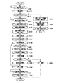
図6は、ドットインパクトプリンター10に記録媒体Sとして小切手が挿入された場合に実行される処理について説明するフローチャートである。ドットインパクトプリンター10が備えるCPU40は、まず、記録媒体Sが手差口15に挿入され、媒体端センサー47によって記録媒体Sの先端が検出されると(ステップS10;Yes)、整列板28を記録媒体Sの搬送経路P内に突出させると共に、媒体搬送モーター26を動作させて整列処理を実行する(ステップS11)。これにより、記録媒体Sの搬送方向の傾き(スキュー)が補正されて整列されると共に、記録媒体Sの先端の位置合わせが実行される。   FIG. 6 is a flowchart for explaining processing executed when a check is inserted as the recording medium S into the dot impact printer 10. The CPU 40 provided in the dot impact printer 10 first records the alignment plate 28 when the recording medium S is inserted into the manual feed slot 15 and the leading edge of the recording medium S is detected by the medium edge sensor 47 (step S10; Yes). The media S is projected into the transport path P of the medium S, and the medium transport motor 26 is operated to execute the alignment process (step S11). Thereby, the inclination (skew) in the transport direction of the recording medium S is corrected and aligned, and the alignment of the leading end of the recording medium S is executed.

次いで、CPU40は、検出した記録媒体Sが小切手であるか、或いは通帳であるかを判別する(ステップS12)。ここで、CPU40は、ホストコンピューター200から送信される情報を取得し、この情報に基づいて記録媒体Sの種類を判別してもよいし、或いは、媒体端センサー47や媒体幅センサー55を用いて記録媒体Sの先端や側端の位置を検出し、この位置やサイズに基づいて記録媒体Sの種類を判別してもよい。或いは、媒体端センサー47や媒体幅センサー55を用いて検出した記録媒体Sの先端や側端の位置に基づき、磁気ヘッド34によりMICR情報MSの読み取りを試行し、この読み取りの試行によりMICR情報MSが所定位置に有るか否かを判定することで、記録媒体Sの種類を判別してもよい。本実施形態では、CPU40は、ホストコンピューター200から、記録媒体Sの種類(小切手又は通帳)を特定するための情報と、記録媒体Sが小切手である場合には、例えば、小切手のサイズに関する情報と、MICR情報MSが記録された位置に関する情報と、搬送距離に関する情報を取得し、これらの情報に基づいて小切手か通帳かを判別する。   Next, the CPU 40 determines whether the detected recording medium S is a check or a passbook (step S12). Here, the CPU 40 may acquire information transmitted from the host computer 200 and determine the type of the recording medium S based on this information, or may use the medium edge sensor 47 or the medium width sensor 55. The position of the leading edge or side edge of the recording medium S may be detected, and the type of the recording medium S may be determined based on the position or size. Alternatively, based on the position of the leading edge or side edge of the recording medium S detected using the medium edge sensor 47 or the medium width sensor 55, the magnetic head 34 tries to read the MICR information MS. The type of the recording medium S may be determined by determining whether or not is at a predetermined position. In the present embodiment, the CPU 40 receives information for specifying the type (check or passbook) of the recording medium S from the host computer 200, and information on the size of the check when the recording medium S is a check. The information about the position where the MICR information MS is recorded and the information about the transport distance are acquired, and it is determined based on these information whether it is a check or a passbook.

ここで、記録媒体Sが小切手である場合(ステップS12;Yes)、CPU40は、ホストコンピューター200から、MICR情報の読み取り命令を受信したか否かを判定する(ステップS13)。そして、CPU40は、MICR情報の読み取り命令を受信したと判定した場合(ステップS13;Yes)にはステップS14に進む。   If the recording medium S is a check (step S12; Yes), the CPU 40 determines whether or not a MICR information read command has been received from the host computer 200 (step S13). If the CPU 40 determines that the MICR information read command has been received (step S13; Yes), the CPU 40 proceeds to step S14.

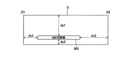
ここで、CPU40は、ホストコンピューター200から、読み取ろうとする記録媒体Sの種類(小切手又は通帳)を特定するための情報等をステップS12で取得する際に、合わせて、MICR情報の読み取り命令を受信してもよい。具体的な例を挙げて説明すると、例えば、図7に示すように、MICR情報MSの記録媒体Sにおける4辺からのオフセット距離dx1,dx2,dy1,dy2に関する情報と、整列板28による整列位置から、MICR情報MSが磁気データ読書部29で読み取り可能な位置に到達するまでの搬送距離Y1に関する情報と、記録媒体Sの先端が表面スキャナー111及び裏面スキャナー112に到達するまでの搬送距離Y2に関する情報と、記録媒体Sの後端が表面スキャナー111及び裏面スキャナー112に到達するまでの搬送距離Y3に関する情報とを受信する。なお、ホストコンピューター200から取得する情報は上記の例に限らず、これら以外の情報を取得してもよいし、他の情報を上記の情報に代えて取得してもよい。   Here, the CPU 40 receives a MICR information read command from the host computer 200 when acquiring information for specifying the type (check or passbook) of the recording medium S to be read in step S12. May be. For example, as shown in FIG. 7, for example, as shown in FIG. 7, information on offset distances dx1, dx2, dy1, dy2 from four sides of the recording medium S of MICR information MS, and an alignment position by the alignment plate 28 To the transport distance Y1 until the MICR information MS reaches a position readable by the magnetic data reading unit 29, and the transport distance Y2 until the leading edge of the recording medium S reaches the front scanner 111 and the back scanner 112. Information and information regarding the transport distance Y3 until the trailing edge of the recording medium S reaches the front surface scanner 111 and the rear surface scanner 112 are received. The information acquired from the host computer 200 is not limited to the above example, but other information may be acquired, or other information may be acquired instead of the above information.

そして、CPU40は、整列板28を搬送経路Pから退避させると共に、少なくとも記録媒体Sの先端が媒体幅センサー55の直下に達するまで記録媒体Sを媒体搬送機構100により搬送させた後、キャリッジ駆動モーター56(図5)を駆動してキャリッジ19を主走査方向に走査し、媒体幅センサー55からの出力信号及びキャリッジ19の主走査方向の位置に基づいて記録媒体Sの幅方向の位置を検出する(ステップS14)。より具体的には、記録媒体SのY方向については、ステップS11の整列処理によってその先端の位置合わせが行われるが、X方向については位置合わせが行われておらず(記録媒体Sを手差口15のどこに挿入してもよいため)、その位置が不明であることから、ステップS13の処理によってX方向についての紙端位置X1,X2(図7参照)が検出される。このようにして検出された紙端位置X1,X2は、RAM41に格納される。   Then, the CPU 40 retracts the alignment plate 28 from the transport path P and transports the recording medium S by the medium transport mechanism 100 until at least the front end of the recording medium S reaches just below the medium width sensor 55, and then the carriage drive motor. 56 (FIG. 5) is driven to scan the carriage 19 in the main scanning direction, and the position in the width direction of the recording medium S is detected based on the output signal from the medium width sensor 55 and the position of the carriage 19 in the main scanning direction. (Step S14). More specifically, in the Y direction of the recording medium S, the leading edge is aligned by the alignment process in step S11, but the alignment in the X direction is not performed (the recording medium S is manually inserted). Since the position is unknown, the paper edge positions X1 and X2 (see FIG. 7) in the X direction are detected by the process of step S13. The paper end positions X1 and X2 detected in this way are stored in the RAM 41.

さらに、CPU40は、記録媒体Sを媒体搬送機構100により搬送させながら媒体端センサー47の出力信号を監視し、記録媒体Sの後端位置を検出する(ステップS15)。   Further, the CPU 40 monitors the output signal of the medium end sensor 47 while the recording medium S is conveyed by the medium conveying mechanism 100, and detects the rear end position of the recording medium S (step S15).

次に、CPU40は、ホストコンピューター200から受信した上記の情報Y1(MICR情報MSが磁気データ読書部29で読み取り可能な位置に到達するまでの搬送距離)に基づいて、記録媒体Sを媒体搬送機構100により搬送する(ステップS16)。   Next, the CPU 40 moves the recording medium S to the medium transport mechanism based on the information Y1 received from the host computer 200 (the transport distance until the MICR information MS reaches a position readable by the magnetic data reading unit 29). It is conveyed by 100 (step S16).

この結果、記録媒体SのMICR情報MSが磁気データ読書部29で読み取り可能な位置まで搬送される(ステップS14)。その後、CPU40は、ステップS13で検出した紙端位置X1,X2と、ステップS12で受信したオフセット距離dx1,dx2に基づいて、スキャン範囲(X1+dx1)〜(X2−dx2)を計算する。   As a result, the MICR information MS of the recording medium S is conveyed to a position where it can be read by the magnetic data reading unit 29 (step S14). Thereafter, the CPU 40 calculates scan ranges (X1 + dx1) to (X2−dx2) based on the paper end positions X1 and X2 detected in step S13 and the offset distances dx1 and dx2 received in step S12.

なお、実際にスキャンする範囲としては、誤差の影響等を考慮してマージンDを持たせるため、前述したスキャン範囲よりも広い範囲((X1+dx1−D)〜(X2−dx2+D))(ただし、D<dx1,dx2)を設定してもよい。   It should be noted that the actual scanning range has a margin D in consideration of the influence of errors and the like, so that it is wider than the above-described scanning range ((X1 + dx1-D) to (X2-dx2 + D)) (however, D <Dx1, dx2) may be set.

CPU40は、磁気データ読書部29の磁気ヘッド駆動モーター64を駆動し、磁気ヘッドユニット62が上記磁気ヘッドガイド軸60、61に支持されて符号Xで示す主走査方向の当該スキャン範囲内を移動させて(ステップS17)、この磁気ヘッドユニット62の磁気ヘッド34により、記録媒体SのMICR情報MSに対する磁気情報処理の読み取りを実行させる(ステップS18)。このとき、CPU40は、MICR情報MSの主走査方向における存在位置を、磁気ヘッド34からの出力信号と、磁気ヘッド34の主走査方向の位置に基づいて検出し、実測値に基づくオフセット距離としてのdx1’,dx2’を求める。なお、オフセット距離としてのdx1’,dx2’を求めるのではなく、MICR情報MSの存在位置を直接求めるようにしてもよい。なお、求められたオフセット距離dx1’,dx2’は、RAM41に格納される。一方、磁気ヘッド34によって読み取られた情報(MICR情報)は、ゲートアレイ45によってデジタル化され、CPU40に出力される。CPU40は、ゲートアレイ45から供給されたデータに基づいて、文字情報を解析し、テキスト情報に変換する(ステップS19)。   The CPU 40 drives the magnetic head drive motor 64 of the magnetic data reading unit 29, and the magnetic head unit 62 is supported by the magnetic head guide shafts 60 and 61 to move within the scanning range in the main scanning direction indicated by the symbol X. (Step S17), the magnetic head 34 of the magnetic head unit 62 reads the magnetic information processing for the MICR information MS of the recording medium S (Step S18). At this time, the CPU 40 detects the presence position of the MICR information MS in the main scanning direction based on the output signal from the magnetic head 34 and the position of the magnetic head 34 in the main scanning direction, and as an offset distance based on the actual measurement value. dx1 ′ and dx2 ′ are obtained. Instead of obtaining dx1 'and dx2' as offset distances, the location of MICR information MS may be obtained directly. The obtained offset distances dx1 'and dx2' are stored in the RAM 41. On the other hand, information (MICR information) read by the magnetic head 34 is digitized by the gate array 45 and output to the CPU 40. The CPU 40 analyzes the character information based on the data supplied from the gate array 45 and converts it into text information (step S19).

CPU40は、ステップS19におけるMICR情報MSの解析処理において、解析不能な文字が存在したか否かを判別する(ステップS20)。ここで、解析不能な文字が存在した場合(ステップS20;Yes)にはステップS21に進み、それ以外の場合(ステップS20;No)にはステップS26に進む。例えば、ステップS19における解析処理において得られた情報が、「01?3456789」であり、第3番目の文字(この例では「?」とされている)が解析不能であった場合には、ステップS20においてYesと判定され、ステップS21に進む。   The CPU 40 determines whether or not there is a character that cannot be analyzed in the analysis process of the MICR information MS in step S19 (step S20). If there is a character that cannot be analyzed (step S20; Yes), the process proceeds to step S21, and otherwise (step S20; No), the process proceeds to step S26. For example, if the information obtained in the analysis process in step S19 is “01? 3456789” and the third character (in this example, “?”) Cannot be analyzed, In S20, it is determined Yes and the process proceeds to step S21.

次に、CPU40は、ステップS13において受信した、記録媒体Sの先端が表面スキャナー111及び裏面スキャナー112に到達するまでの搬送距離Y2に関する情報に基づいて、記録媒体Sが表面スキャナー111及び裏面スキャナー112の読み取り可能な位置まで移動させる(ステップS21)。   Next, the CPU 40 receives the recording medium S from the front surface scanner 111 and the rear surface scanner 112 based on the information received in step S13 regarding the transport distance Y2 until the leading edge of the recording medium S reaches the front surface scanner 111 and the rear surface scanner 112. Is moved to a readable position (step S21).

そして、CPU40は、MICR情報MSの光学的な読み取りを実行し(ステップS22)、ステップS23に移行する。ステップS22で、CPU40は、記録媒体Sを媒体搬送機構100により副走査方向に搬送させながら、表面スキャナー111及び裏面スキャナー112によって、記録媒体Sの裏面と、表面とを同時に読み取り、画像信号に変換しゲートアレイ45に供給する。続いて、CPU40は、ステップS12において受信した、記録媒体Sの後端が表面スキャナー111及び裏面スキャナー112に到達するまでの搬送距離Y3に関する情報に基づいてスキャンを停止する。このとき、表面スキャナー111及び裏面スキャナー112によって記録媒体Sを読み取るX方向の範囲は、ステップS13において検出された幅方向の位置X1,X2に基づいて決定する。すなわち、ゲートアレイ45は、幅方向の位置に対応する範囲の受光部から出力される信号のみを取得すると共に、搬送距離Y2〜Y3で指定される期間だけ、受光部から出力される信号を取得する。なお、搬送距離Y3については、媒体端センサー47によって検出される記録媒体Sの先端及び後端から求められる値に基づいて求めるようにしてもよい。すなわち、媒体端センサー47によって検出される記録媒体Sの先端及び後端の搬送距離の差分値を求め、当該差分値をY2に加算することによりY3を求めるようにしてもよい。   Then, the CPU 40 performs optical reading of the MICR information MS (step S22), and proceeds to step S23. In step S22, the CPU 40 simultaneously reads the back surface and the front surface of the recording medium S by the front surface scanner 111 and the back surface scanner 112 while the recording medium S is transported in the sub-scanning direction by the medium transport mechanism 100, and converts it into an image signal. To the gate array 45. Subsequently, the CPU 40 stops scanning based on the information related to the transport distance Y3 received in step S12 until the trailing edge of the recording medium S reaches the front surface scanner 111 and the rear surface scanner 112. At this time, the range in the X direction in which the recording medium S is read by the front surface scanner 111 and the back surface scanner 112 is determined based on the positions X1 and X2 in the width direction detected in step S13. That is, the gate array 45 acquires only the signal output from the light receiving unit in the range corresponding to the position in the width direction, and acquires the signal output from the light receiving unit only for the period specified by the transport distance Y2 to Y3. To do. The transport distance Y3 may be obtained based on values obtained from the leading edge and the trailing edge of the recording medium S detected by the medium edge sensor 47. That is, Y3 may be obtained by obtaining a difference value between the transport distances of the leading edge and the trailing edge of the recording medium S detected by the medium edge sensor 47 and adding the difference value to Y2.

ゲートアレイ45は、画像信号を量子化してデジタルデータとしての画像データに変換し、CPU40に供給する。CPU40は、得られた画像データを、RAM41に格納する。なお、このようにして格納された小切手の画像データは、後述するステップS26において、I/F43を介してホストコンピューター200に転送される。ホストコンピューター200では、転送された情報を、受入銀行から支払銀行に伝送することによって決済を行う。すなわち、現物の小切手を輸送して処理する代わりに、小切手の券面の情報を画像データに変換して、受入銀行から支払銀行のホストコンピューターに伝送することにより、電子的な決済が実行される。   The gate array 45 quantizes the image signal, converts it into image data as digital data, and supplies the image data to the CPU 40. The CPU 40 stores the obtained image data in the RAM 41. Note that the image data of the check stored in this way is transferred to the host computer 200 via the I / F 43 in step S26 described later. The host computer 200 performs settlement by transmitting the transferred information from the receiving bank to the paying bank. That is, instead of transporting and processing the actual check, electronic check is executed by converting the check face information into image data and transmitting it to the host computer of the payment bank from the receiving bank.

ステップS23では、CPU40は、ステップS22において、裏面スキャナー112によって読み取られた画像データに基づいて、文字の解析処理を実行する。具体的には、CPU40は、ステップS15の処理において取得された、実測されたオフセット距離としてのdx1’,dx2’と、ステップS13で受信したdy1,dy2に基づいて、画像データからMICR情報MSが含まれる領域を特定し、当該領域に含まれる画像データを抽出し、抽出された画像データに対して解析処理を実行する。なお、当該解析処理は、OCR処理として一般的に知られている処理を用いることができる。このような処理により、先ほどの例では、解析結果として、例えば、「012345678?」を得る。なお、この例では、最後の文字(この例では「?」とされている)は解析に失敗している。   In step S23, the CPU 40 executes character analysis processing based on the image data read by the back surface scanner 112 in step S22. Specifically, the CPU 40 obtains the MICR information MS from the image data based on dx1 ′ and dx2 ′ as the actually measured offset distance acquired in the process of step S15 and dy1 and dy2 received in step S13. An area included is specified, image data included in the area is extracted, and analysis processing is executed on the extracted image data. The analysis process can use a process generally known as an OCR process. By such processing, in the previous example, for example, “012345678?” Is obtained as the analysis result. In this example, the last character (in this example, “?”) Has failed to be analyzed.

次に、CPU40は、ステップS19で解析不能であった文字の解析に成功したか否かを判定し(ステップS24)、成功した場合(ステップS24;Yes)にはステップS25に進み、それ以外の場合(ステップS24;No)にはステップS29に進む。   Next, the CPU 40 determines whether or not the character that could not be analyzed in step S19 has been successfully analyzed (step S24), and if successful (step S24; Yes), the process proceeds to step S25. In the case (step S24; No), the process proceeds to step S29.

先ほどの例では、ステップS19における解析処理において、解析不能であった文字(第3番目の文字「2」)の解析に成功しているので、ステップS25に進む。   In the previous example, in the analysis process in step S19, the character that could not be analyzed (the third character “2”) has been successfully analyzed, and the process proceeds to step S25.

ステップS25では、CPU40は、ステップS19とステップS23における解析結果を統合する。すなわち、CPU40は、ステップS19における解析結果によって得られた「01?3456789」と、ステップS23における解析結果によって得られた「012345678?」とを統合することによって「0123456789」を得る。   In step S25, the CPU 40 integrates the analysis results in step S19 and step S23. That is, the CPU 40 obtains “012345789” by integrating “01? 3456789” obtained from the analysis result in step S19 and “012345678?” Obtained from the analysis result in step S23.

一方、ステップS24において、解析不能文字の解析に失敗したと判定した場合には、ステップS29に進み、CPU40は、ホストコンピューター200に対してエラーが発生したことを通知し、処理を終了する。   On the other hand, if it is determined in step S24 that the analysis of the unanalyzable character has failed, the process proceeds to step S29, where the CPU 40 notifies the host computer 200 that an error has occurred and ends the process.

次に、CPU40は、解析処理によって得られたMICR情報MSをI/F43を介してホストコンピューター200に送信すると共に、ステップS22の読み取り処理によって読み取られてRAM41に格納されている記録媒体Sの両面の画像データをI/F43を介してホストコンピューター200に送信する(ステップS26)。   Next, the CPU 40 transmits the MICR information MS obtained by the analysis processing to the host computer 200 via the I / F 43, and also reads both sides of the recording medium S read by the reading processing of step S22 and stored in the RAM 41. Is sent to the host computer 200 via the I / F 43 (step S26).

ここで、CPU40は、ホストコンピューター200から裏書き印刷の実行命令を受信するまで待機し(ステップS27)、裏書き印刷の実行命令を受信した場合は、媒体搬送モーター26を逆転させ、記録媒体Sを記録ヘッド18の下まで搬送すると共に、キャリッジ駆動モーター56及び記録ヘッド18を駆動し、記録媒体Sの裏面に処理済みを示す裏書き印刷を行う(ステップS28)。そして、裏書き印刷が完了すると、CPU40は、媒体搬送モーター26を更に回転させ、記録媒体Sを手差口15から排出する。   Here, the CPU 40 waits until receiving an execution command for the endorsement printing from the host computer 200 (step S27). When the execution command for the endorsement printing is received, the medium transport motor 26 is reversed to record the recording medium S. And the carriage drive motor 56 and the recording head 18 are driven, and the end printing is performed on the back surface of the recording medium S to indicate the completion of processing (step S28). When the endorsement printing is completed, the CPU 40 further rotates the medium transport motor 26 and discharges the recording medium S from the manual feed port 15.

このとき、記録媒体Sを排出させずに、再度、表面スキャナー111及び裏面スキャナー112によって、記録媒体Sの表裏両面の全面をスキャンし、処理済みとなった小切手の券面の画像データを生成して、この画像データを受入銀行から支払銀行のホストコンピューターに伝送することにより、最終処理画像による電子的な決済が実行されるようにしてもよい。この場合、小切手が処理済みとなったことを示すデータとして画像データを利用することで、決済の信頼性及び正当性が担保される。   At this time, without discharging the recording medium S, the front surface scanner 111 and the back surface scanner 112 scan the entire front and back surfaces of the recording medium S again to generate image data on the check face that has been processed. The image data may be transmitted from the receiving bank to the host computer of the payment bank, so that electronic settlement based on the final processed image may be executed. In this case, the reliability and legitimacy of the settlement is ensured by using the image data as data indicating that the check has been processed.

なお、以上の説明は、記録媒体Sとして小切手が挿入された場合について説明したが、記録媒体Sとして通帳が挿入された場合には、次のような処理が実行される。すなわち、ステップS12において、検出した記録媒体Sが通帳である(小切手でない)と判別した場合、CPU40は、ホストコンピューター200から通帳に関する処理を実施するように命令がなされることに対応して、搬送経路P内に整列板28によって通帳の傾きを補正した後、記録媒体Sを媒体搬送機構100により搬送させ、磁気データ読書部29の磁気ヘッド駆動モーター64を駆動し、磁気ヘッド34によって、記録媒体Sの磁気ストライプに対する情報の磁気的な読み取り、及び/又は書き込みを実行する(ステップS31)。さらにCPU40は、通帳である記録媒体Sの記録面に、記録ヘッド18によって文字を含む画像を記録し(ステップS32)、媒体搬送機構100によって記録媒体Sを手差口15から排出して(ステップS33)、本処理を終了する。   In the above description, the case where a check is inserted as the recording medium S has been described. However, when a bankbook is inserted as the recording medium S, the following processing is executed. That is, if it is determined in step S12 that the detected recording medium S is a passbook (not a check), the CPU 40 carries the transport in response to an instruction from the host computer 200 to execute processing related to the passbook. After correcting the inclination of the passbook in the path P by the alignment plate 28, the recording medium S is conveyed by the medium conveying mechanism 100, the magnetic head driving motor 64 of the magnetic data reading unit 29 is driven, and the magnetic head 34 performs the recording medium. Magnetic reading and / or writing of information on the magnetic stripe of S is executed (step S31). Further, the CPU 40 records an image including characters by the recording head 18 on the recording surface of the recording medium S as a passbook (step S32), and ejects the recording medium S from the manual feed slot 15 by the medium transport mechanism 100 (step S32). (S33) This process is terminated.

次に、上記構成のドットインパクトプリンター10に認証機能を追加した認証機能付きドットインパクトプリンター10Aについて説明する。   Next, a dot impact printer 10A with an authentication function obtained by adding an authentication function to the dot impact printer 10 having the above configuration will be described.

以下、上記構成のドットインパクトプリンター10との相違点を中心に説明し、同一の構成については同一の符号を付して適宜その説明を省略する。   Hereinafter, the difference from the dot impact printer 10 having the above configuration will be mainly described, and the same components will be denoted by the same reference numerals, and the description thereof will be omitted as appropriate.

図8は、認証機能付きドットインパクトプリンター10A(プリンター本体11)の外観斜視図である。図9は、認証機能付きドットインパクトプリンター10Aの側断面図である。図10は、認証機能付きドットインパクトプリンター10Aの機能的構成を示すブロック図である。   FIG. 8 is an external perspective view of a dot impact printer 10A (printer body 11) with an authentication function. FIG. 9 is a side sectional view of the dot impact printer 10A with an authentication function. FIG. 10 is a block diagram illustrating a functional configuration of a dot impact printer 10A with an authentication function.

図8〜図10に示すように、認証機能付きドットインパクトプリンター10Aは、近距離無線通信装置70(無線通信部)を備える。   As shown in FIGS. 8 to 10, the dot impact printer 10 </ b> A with an authentication function includes a short-range wireless communication device 70 (wireless communication unit).

近距離無線通信装置70は、IDカードS1(媒体)の内部に予め記録(記憶)された情報を無線(非接触)で読み取る非接触型の無線通信部で、典型的には、近距離無線通信装置本体70aとアンテナ70bとによって構成される。近距離無線通信装置本体70aとアンテナ70bとは、通信ケーブル(図示せず)で接続される。   The short-range wireless communication device 70 is a non-contact type wireless communication unit that wirelessly (non-contact) reads information recorded (stored) in the ID card S1 (medium) in advance. The communication device main body 70a and the antenna 70b are configured. The short-range wireless communication device main body 70a and the antenna 70b are connected by a communication cable (not shown).

近距離無線通信装置本体70aは、例えば、RFIDリーダ/ライタやNFCリーダ/ライタで、例えば、下部ケース14の底面に配置される。   The near field communication device main body 70a is, for example, an RFID reader / writer or an NFC reader / writer, and is disposed on the bottom surface of the lower case 14, for example.

IDカードS1は、近距離無線通信装置70によって無線(非接触)で読み取られる情報が予め記録(記憶)されたメモリー(図示せず)等を内蔵したICカードで、例えば、RFIDカードやNFCカードによって構成される。近距離無線通信装置70は、ドットインパクトプリンター10A(筐体)内に収容された状態のIDカードS1の内部に予め記録された情報を無線で読み取る。IDカードS1(メモリー)に予め記録された情報としては、例えば、氏名、生年月日、識別番号、顔写真(画像データ)がある。なお、IDカードS1がドットインパクトプリンター10A(筐体)内に収容された状態とは、IDカードS1がドットインパクトプリンター10A(筐体)内に取り込まれた状態、すなわち、IDカードS1の後端が手差口15から突出せず、かつ、IDカードS1の全体がドットインパクトプリンター10A(筐体)内に収容された状態のことである。   The ID card S1 is an IC card having a built-in memory (not shown) in which information to be read wirelessly (contactlessly) by the short-range wireless communication device 70 is stored (not shown), for example, an RFID card or an NFC card. Consists of. The short-range wireless communication device 70 wirelessly reads information recorded in advance in the ID card S1 accommodated in the dot impact printer 10A (housing). Examples of information recorded in advance in the ID card S1 (memory) include a name, a date of birth, an identification number, and a face photograph (image data). The state in which the ID card S1 is accommodated in the dot impact printer 10A (housing) means that the ID card S1 is taken into the dot impact printer 10A (housing), that is, the rear end of the ID card S1. Is a state in which the entire ID card S1 is accommodated in the dot impact printer 10A (housing).

また、IDカードS1の表面(又は裏面)には、表面スキャナー111及び裏面スキャナー112(光学読取部)の少なくとも一方によって光学的に読み取られる情報が予め記録(印刷)される。表面スキャナー111及び裏面スキャナー112(光学読取部)の少なくとも一方は、ドットインパクトプリンター10A(筐体)内に収容された状態のIDカードS1の表面に予め記録された情報を光学的に読み取る。IDカードS1の表面(又は裏面)に予め記録された情報としては、例えば、氏名、生年月日、識別番号、顔写真(画像データ)がある。なお、IDカードS1の表面(又は裏面)に記録された情報とIDカードS1の内部(メモリー)に記録された情報とは、同一(完全同一)であってもよいし、一部異なっていてもよい(一部同一)。   In addition, information that is optically read by at least one of the front surface scanner 111 and the back surface scanner 112 (optical reading unit) is recorded (printed) in advance on the front surface (or back surface) of the ID card S1. At least one of the front surface scanner 111 and the back surface scanner 112 (optical reading unit) optically reads information recorded in advance on the surface of the ID card S1 accommodated in the dot impact printer 10A (housing). Examples of information recorded in advance on the front surface (or back surface) of the ID card S1 include name, date of birth, identification number, and face photograph (image data). The information recorded on the front surface (or back surface) of the ID card S1 and the information recorded in the ID card S1 (memory) may be the same (completely identical) or may be partially different. It is good (some are the same).

印刷部(記録ヘッド18、キャリッジ19、キャリッジガイド軸31、キャリッジ駆動モーター56、タイミングベルト等)、近距離無線通信装置70(無線通信部)、表面スキャナー111及び裏面スキャナー112(光学読取部)は、図9に示すように、IDカードS1の搬送経路P(搬送路)に沿って並べて配置される。   The printing unit (recording head 18, carriage 19, carriage guide shaft 31, carriage drive motor 56, timing belt, etc.), short-range wireless communication device 70 (wireless communication unit), front surface scanner 111, and rear surface scanner 112 (optical reading unit) As shown in FIG. 9, they are arranged side by side along the transport path P (transport path) of the ID card S1.

IDカードS1は、手差口15から挿入されて整列板28によって整列された後、その整列位置から、媒体搬送機構100(搬送機構)によってドットインパクトプリンター10A(筐体)内に引き込まれ、近距離無線通信装置70によって読み取り可能な位置に到達するまで搬送される。なお、近距離無線通信装置70によって読み取り可能な位置は、IDカードS1の後端が手差口15から突出せず、かつ、IDカードS1の全体がドットインパクトプリンター10A(筐体)内に収容された状態となる位置である。   After the ID card S1 is inserted from the manual feed slot 15 and aligned by the alignment plate 28, the ID card S1 is drawn into the dot impact printer 10A (housing) from the alignment position by the medium transport mechanism 100 (transport mechanism). It is conveyed until it reaches a position where it can be read by the distance wireless communication device 70. The position that can be read by the short-range wireless communication device 70 is such that the rear end of the ID card S1 does not protrude from the manual feed slot 15, and the entire ID card S1 is accommodated in the dot impact printer 10A (housing). It is the position that will be in the state.

近距離無線通信装置70は、当該近距離無線通信装置70によって読み取り可能な位置に到達したIDカードS1の内部(メモリー)に記録された情報を無線(非接触)で読み取る。なお、近距離無線通信装置70は、IDカードS1の内部(メモリー)に記録された情報の全部を読み取ってもよいし、IDカードS1の内部(メモリー)に記録された情報の一部(例えば、識別番号のみ)を読み取ってもよい。   The short-range wireless communication device 70 wirelessly (contactlessly) reads information recorded in the inside (memory) of the ID card S1 that has reached a position readable by the short-range wireless communication device 70. The short-range wireless communication device 70 may read all of the information recorded in the ID card S1 (memory) or a part of the information recorded in the ID card S1 (memory) (for example, , Identification number only).

アンテナ70bは、IDカードS1の内部に記録された情報を受信するための非接触型のアンテナで、近距離無線通信装置70によって読み取り可能な位置に到達したIDカードS1の上方に、例えば、主走査方向Xに延びるフレーム(図示せず)に固定された状態で配置される。アンテナ70bは、例えば、整列板28(媒体整列部)の下流に配置される。なお、アンテナ70bの中心と近距離無線通信装置70によって読み取り可能な位置に到達したIDカードS1の中心とは、上下方向(図9中上下方向)に関し、一致しているのが望ましいが、前後方向(図9中左右方向)に若干ズレていてもよい。   The antenna 70b is a non-contact type antenna for receiving information recorded in the ID card S1, and is located above the ID card S1 that has reached a position readable by the short-range wireless communication device 70, for example, It is arranged in a fixed state on a frame (not shown) extending in the scanning direction X. The antenna 70b is disposed, for example, downstream of the alignment plate 28 (medium alignment unit). It is desirable that the center of the antenna 70b and the center of the ID card S1 that has reached a position readable by the short-range wireless communication device 70 coincide with each other in the vertical direction (vertical direction in FIG. 9). It may be slightly shifted in the direction (left-right direction in FIG. 9).

次に、認証機能付きドットインパクトプリンター10Aの動作例1(制御方法1)について説明する。   Next, an operation example 1 (control method 1) of the dot impact printer 10A with an authentication function will be described.

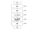
図11は、認証機能付きドットインパクトプリンター10Aの動作例1(制御方法1)である認証処理について説明するフローチャートである。   FIG. 11 is a flowchart illustrating an authentication process that is an operation example 1 (control method 1) of the dot impact printer 10A with an authentication function.

本動作例1では、以下に説明するように、無線通信部(近距離無線通信装置70)は、光学読取部(表面スキャナー111及び裏面スキャナー112)による読取実行前に、搬送停止状態のIDカードS1から、その内部に予め記録(記憶)された情報を無線(非接触)で読み取る。   In the first operation example, as will be described below, the wireless communication unit (short-range wireless communication device 70) is configured to stop the conveyance of the ID card before the reading by the optical reading unit (the front surface scanner 111 and the back surface scanner 112). From S1, information recorded (stored) in advance is read wirelessly (non-contact).

以下の処理は、主に、CPU40が、EEPROM42からRAM41に読み込まれた所定プログラム(制御プログラム等)を実行することによって実現される。   The following processing is mainly realized by the CPU 40 executing a predetermined program (control program or the like) read from the EEPROM 42 to the RAM 41.

まず、CPU40は、整列処理を実行する(ステップS40)。具体的には、CPU40は、ホストコンピューター200から、認証を開始する旨の命令を受信し、かつ、IDカードS1が手差口15に挿入され、媒体端センサー47によってIDカードS1の先端が検出されると、整列板28をIDカードS1の搬送経路P(搬送路)内に突出させると共に、媒体搬送モーター26を動作させて整列処理を実行する。これにより、IDカードS1の搬送方向の傾き(スキュー)が補正されて整列されると共に、IDカードS1の先端の位置合わせが実行される。   First, the CPU 40 executes alignment processing (step S40). Specifically, the CPU 40 receives an instruction to start authentication from the host computer 200, and the ID card S1 is inserted into the manual feed slot 15, and the leading edge of the ID card S1 is detected by the medium edge sensor 47. Then, the alignment plate 28 is projected into the conveyance path P (conveyance path) of the ID card S1, and the medium conveyance motor 26 is operated to execute the alignment process. As a result, the inclination (skew) in the conveyance direction of the ID card S1 is corrected and aligned, and the leading edge of the ID card S1 is aligned.

次に、CPU40は、給紙処理を実行する(ステップS42)。具体的には、CPU40は、整列板28を搬送経路Pから退避させると共に、IDカードS1をその整列位置から、媒体搬送機構100によってドットインパクトプリンター10A(筐体)内に引き込み、近距離無線通信装置70によって読み取り可能な位置に到達するまで搬送する。この近距離無線通信装置70によって読み取り可能な位置に到達したIDカードS1は、その後端が手差口15から突出せず、かつ、その全体がドットインパクトプリンター10A(筐体)内に収容された状態で停止する(搬送停止状態)。   Next, the CPU 40 executes a paper feed process (step S42). Specifically, the CPU 40 retracts the alignment plate 28 from the conveyance path P, and pulls the ID card S1 from the alignment position into the dot impact printer 10A (housing) by the medium conveyance mechanism 100 to perform short-distance wireless communication. It is conveyed until it reaches a position that can be read by the apparatus 70. The ID card S1 that has reached a position that can be read by the short-range wireless communication device 70 does not protrude from the manual feed slot 15 at the rear end, and is entirely accommodated in the dot impact printer 10A (housing). Stop in the state (conveyance stop state).

次に、CPU40は、IDカード読み取り処理を実行する(ステップS44)。このIDカード読み取り処理は、IDカードS1の全体がドットインパクトプリンター10A(筐体)内に収容された状態で実行される。具体的には、CPU40は、ホストコンピューター200から、IDカードS1の読み取り命令を受信したか否かを判定し、当該命令を受信したと判定した場合、搬送停止状態のIDカードS1から、その内部に予め記録(記憶)された情報を近距離無線通信装置70によって無線(非接触)で読み取る。なお、ホストコンピューター200から、IDカードS1の読み取り命令を受信したか否かの判定は省略してもよい。   Next, the CPU 40 executes an ID card reading process (step S44). This ID card reading process is executed in a state where the entire ID card S1 is accommodated in the dot impact printer 10A (housing). Specifically, the CPU 40 determines whether or not a command for reading the ID card S1 has been received from the host computer 200. If it is determined that the command has been received, the CPU 40 determines whether the command is received from the ID card S1 in the transport stop state. The information previously recorded (stored) is read wirelessly (non-contact) by the short-range wireless communication device 70. Note that the determination as to whether or not a command for reading the ID card S1 has been received from the host computer 200 may be omitted.

このように、本動作例1では、光学読取部(表面スキャナー111及び裏面スキャナー112)による読取実行前に、無線通信部(近距離無線通信装置70)による読み取りを、IDカードS1の搬送停止状態で行う。   As described above, in the first operation example, before the reading is performed by the optical reading unit (the front surface scanner 111 and the back surface scanner 112), the reading by the wireless communication unit (the short-range wireless communication device 70) is performed in the conveyance stop state of the ID card S1. To do.

CPU40は、近距離無線通信装置70によって読み取った情報を、RAM41に格納する。なお、このようにして格納された情報は、所定のタイミングで、I/F43を介してホストコンピューター200に転送される。   The CPU 40 stores information read by the short-range wireless communication device 70 in the RAM 41. The information stored in this way is transferred to the host computer 200 via the I / F 43 at a predetermined timing.

次に、CPU40は、スキャン読取処理を実行する(ステップS46)。このスキャン読取処理も、IDカードS1の全体がドットインパクトプリンター10A(筐体)内に収容された状態で実行される。具体的には、CPU40は、ホストコンピューター200から、スキャン命令を受信したか否かを判定し、当該命令を受信したと判定した場合、IDカードS1を媒体搬送機構100によって、表面スキャナー111及び裏面スキャナー112の少なくとも一方によって読み取り可能な位置に到達するまで搬送し、さらに、IDカードS1を媒体搬送機構100により副走査方向に搬送させながら、表面スキャナー111及び裏面スキャナー112の少なくとも一方によって、IDカードS1の表面及び裏面の少なくとも一方を読み取り、画像信号に変換しゲートアレイ45に供給する。なお、ホストコンピューター200から、スキャン命令を受信したか否かの判定は省略してもよい。   Next, the CPU 40 executes a scan reading process (step S46). This scan reading process is also executed in a state where the entire ID card S1 is accommodated in the dot impact printer 10A (housing). Specifically, the CPU 40 determines whether or not a scan command has been received from the host computer 200, and if it is determined that the command has been received, the front side scanner 111 and the back side of the ID card S1 are transferred by the medium transport mechanism 100. The ID card S1 is transported until it reaches a position readable by at least one of the scanners 112, and further, the ID card S1 is transported in the sub-scanning direction by the medium transport mechanism 100, and at least one of the front surface scanner 111 and the rear surface scanner 112 is used. At least one of the front and back surfaces of S1 is read, converted into an image signal, and supplied to the gate array 45. Note that the determination of whether or not a scan command has been received from the host computer 200 may be omitted.

ゲートアレイ45は、画像信号を量子化してデジタルデータとしての画像データに変換し、CPU40に供給する。CPU40は、得られた画像データを、RAM41に格納する。なお、このようにして格納された情報は、所定のタイミングで、I/F43を介してホストコンピューター200に転送される。   The gate array 45 quantizes the image signal, converts it into image data as digital data, and supplies the image data to the CPU 40. The CPU 40 stores the obtained image data in the RAM 41. The information stored in this way is transferred to the host computer 200 via the I / F 43 at a predetermined timing.

ホストコンピューター200では、認証機能付きドットインパクトプリンター10Aから転送される、近距離無線通信装置70によって読み取った情報や表面スキャナー111及び裏面スキャナー112の少なくとも一方によって読み取った情報に基づき、各種の処理を実行する。   The host computer 200 executes various processes based on information read by the short-range wireless communication device 70 and information read by at least one of the front surface scanner 111 and the back surface scanner 112 transferred from the dot impact printer 10A with an authentication function. To do.

例えば、近距離無線通信装置70によって読み取った情報、並びに表面スキャナー111及び裏面スキャナー112の少なくとも一方によって読み取った情報がいずれも識別番号である場合を想定する。この場合、ホストコンピューター200が、両者が一致するか否かを判定し、その結果、両者が一致すると判定した場合、認証が成立した旨の表示を例えばホストコンピューター200に接続されたディスプレイ(図示せず)に表示し、一方、両者が一致しないと判定した場合、認証が成立しない旨の表示を当該ディスプレイに表示することが考えられる。   For example, it is assumed that the information read by the short-range wireless communication device 70 and the information read by at least one of the front surface scanner 111 and the back surface scanner 112 are both identification numbers. In this case, the host computer 200 determines whether or not both match, and as a result, when it is determined that they match, a display (not shown) connected to the host computer 200 is displayed, for example, indicating that the authentication has been established. On the other hand, if it is determined that the two do not match, it is conceivable that a display indicating that the authentication is not established is displayed on the display.

また例えば、近距離無線通信装置70によって読み取った情報、並びに表面スキャナー111及び裏面スキャナー112の少なくとも一方によって読み取った情報がいずれも顔写真である場合を想定する。この場合、両顔写真を例えばホストコンピューター200に接続されたディスプレイ(図示せず)に並べて表示し、オペレーターに両者が一致するか否かを判定させ、その判定結果をホストコンピューター200に接続されたキーボード等の入力装置から入力させることも考えられる。   Further, for example, a case is assumed where the information read by the short-range wireless communication device 70 and the information read by at least one of the front surface scanner 111 and the back surface scanner 112 are both facial photographs. In this case, both face photographs are displayed side by side on a display (not shown) connected to the host computer 200, for example, and the operator determines whether or not they match, and the determination result is connected to the host computer 200. It is also conceivable to input from an input device such as a keyboard.

また例えば、近距離無線通信装置70によって読み取った情報と、表面スキャナー111及び裏面スキャナー112の少なくとも一方によって読み取った情報とを紐付けして(対応付けて)、ホストコンピューター200に接続されたデータベース等の記憶部に記憶しておくことも考えられる。   Further, for example, a database connected to the host computer 200 by associating (associating) information read by the short-range wireless communication device 70 with information read by at least one of the front surface scanner 111 and the back surface scanner 112 It is also conceivable to store them in the storage unit.

そして、CPU40は、排紙処理を実行する(ステップS48)。すなわち、CPU40は、媒体搬送モーター26を更に回転させ、IDカードS1を手差口15から排出する。   Then, the CPU 40 executes a paper discharge process (step S48). That is, the CPU 40 further rotates the medium transport motor 26 and discharges the ID card S1 from the manual feed slot 15.

本動作例1によれば、IDカードS1内部の記録情報の読み取りやIDカードS1表面の記録情報の読み取りにおいて、人が介在するのを排除できる(その結果、セキュリティ面を向上できる)ドットインパクトプリンター10A(認証装置)の制御方法を提供できる。   According to the first operation example, it is possible to eliminate human intervention in reading the recording information inside the ID card S1 and the recording information on the surface of the ID card S1 (as a result, it is possible to improve security). A control method of 10A (authentication apparatus) can be provided.

これは、IDカードS1内部の記録情報の読み取りやIDカードS1表面の記録情報の読み取りを、媒体搬送機構100(搬送機構)によってIDカードS1を搬送することで実現できるため、IDカードS1内部の記録情報の読み取りやIDカードS1表面の記録情報の読み取りに際して、人が介在するのを排除できることによるものである。   This can be realized by reading the recording information inside the ID card S1 and reading the recording information on the surface of the ID card S1 by conveying the ID card S1 by the medium conveying mechanism 100 (conveying mechanism). This is because it is possible to eliminate human intervention when reading recorded information or reading recorded information on the surface of the ID card S1.

また、本動作例1によれば、IDカードS1から、その内部に記録された情報を精度よく読み取ることができる。   Moreover, according to this operation example 1, the information recorded in the ID card S1 can be accurately read.

これは、近距離無線通信装置70(無線通信部)は、搬送状態のIDカードS1からではなく、搬送停止状態のIDカードS1から、その内部に記録された情報を読み取ることによるものである。   This is because the short-range wireless communication device 70 (wireless communication unit) reads information recorded therein from the ID card S1 in the transport stop state, not from the ID card S1 in the transport state.

次に、認証機能付きドットインパクトプリンター10Aの動作例2(制御方法2)について説明する。   Next, an operation example 2 (control method 2) of the dot impact printer 10A with an authentication function will be described.

図12は、認証機能付きドットインパクトプリンター10Aの動作例2(制御方法2)である認証処理について説明するフローチャートである。   FIG. 12 is a flowchart illustrating an authentication process that is an operation example 2 (control method 2) of the dot impact printer 10A with an authentication function.

本動作例2では、以下に説明するように、無線通信部(近距離無線通信装置70)は、光学読取部(表面スキャナー111及び裏面スキャナー112)による読取実行後に、搬送停止状態のIDカードS1から、その内部に予め記録(記憶)された情報を無線(非接触)で読み取る。   In the second operation example, as will be described below, the wireless communication unit (short-range wireless communication device 70) performs the reading stop by the optical reading unit (the front surface scanner 111 and the back surface scanner 112), and then the ID card S1 in the conveyance stopped state. Then, the information recorded (stored) in advance inside is read wirelessly (non-contact).

以下、認証機能付きドットインパクトプリンター10Aの動作例2(制御方法2)との相違点を中心に説明し、同一の動作については適宜その説明を省略する。   Hereinafter, differences from the operation example 2 (control method 2) of the dot impact printer 10A with the authentication function will be mainly described, and the description of the same operations will be appropriately omitted.

以下の処理は、主に、CPU40が、EEPROM42からRAM41に読み込まれた所定プログラム(制御プログラム等)を実行することによって実現される。   The following processing is mainly realized by the CPU 40 executing a predetermined program (control program or the like) read from the EEPROM 42 to the RAM 41.

まず、CPU40は、整列処理を実行する(ステップS50)。具体的には、CPU40は、ホストコンピューター200から、認証を開始する旨の命令を受信し、かつ、IDカードS1が手差口15に挿入され、媒体端センサー47によってIDカードS1の先端が検出されると、整列板28をIDカードS1の搬送経路P(搬送路)内に突出させると共に、媒体搬送モーター26を動作させて整列処理を実行する。これにより、IDカードS1の搬送方向の傾き(スキュー)が補正されて整列されると共に、IDカードS1の先端の位置合わせが実行される。   First, the CPU 40 executes an alignment process (step S50). Specifically, the CPU 40 receives an instruction to start authentication from the host computer 200, and the ID card S1 is inserted into the manual feed slot 15, and the leading edge of the ID card S1 is detected by the medium edge sensor 47. Then, the alignment plate 28 is projected into the conveyance path P (conveyance path) of the ID card S1, and the medium conveyance motor 26 is operated to execute the alignment process. As a result, the inclination (skew) in the conveyance direction of the ID card S1 is corrected and aligned, and the leading edge of the ID card S1 is aligned.

次に、CPU40は、給紙処理を実行する(ステップS52)。具体的には、CPU40は、整列板28を搬送経路Pから退避させると共に、IDカードS1をその整列位置から、媒体搬送機構100によってドットインパクトプリンター10A(筐体)内に引き込む。   Next, the CPU 40 executes a paper feed process (step S52). Specifically, the CPU 40 retracts the alignment plate 28 from the transport path P, and pulls the ID card S1 from the alignment position into the dot impact printer 10A (housing) by the medium transport mechanism 100.

次に、CPU40は、スキャン読取処理を実行する(ステップS54)。このスキャン読取処理は、IDカードS1の全体がドットインパクトプリンター10A(筐体)内に収容された状態で実行される。具体的には、CPU40は、ホストコンピューター200から、スキャン命令を受信したか否かを判定し、当該命令を受信したと判定した場合、IDカードS1を媒体搬送機構100によって、表面スキャナー111及び裏面スキャナー112の少なくとも一方によって読み取り可能な位置に到達するまで搬送し、さらに、IDカードS1を媒体搬送機構100により副走査方向に搬送させながら、表面スキャナー111及び裏面スキャナー112の少なくとも一方によって、IDカードS1の表面及び裏面の少なくとも一方を読み取り、画像信号に変換しゲートアレイ45に供給する。なお、ホストコンピューター200から、スキャン命令を受信したか否かの判定は省略してもよい。   Next, the CPU 40 executes a scan reading process (step S54). This scan reading process is executed in a state where the entire ID card S1 is accommodated in the dot impact printer 10A (housing). Specifically, the CPU 40 determines whether or not a scan command has been received from the host computer 200, and if it is determined that the command has been received, the front side scanner 111 and the back side of the ID card S1 are transferred by the medium transport mechanism 100. The ID card S1 is transported until it reaches a position readable by at least one of the scanners 112, and further, the ID card S1 is transported in the sub-scanning direction by the medium transport mechanism 100, and at least one of the front surface scanner 111 and the rear surface scanner 112 is used. At least one of the front and back surfaces of S1 is read, converted into an image signal, and supplied to the gate array 45. Note that the determination of whether or not a scan command has been received from the host computer 200 may be omitted.

ゲートアレイ45は、画像信号を量子化してデジタルデータとしての画像データに変換し、CPU40に供給する。CPU40は、得られた画像データを、RAM41に格納する。なお、このようにして格納された情報は、所定のタイミングで、I/F43を介してホストコンピューター200に転送される。   The gate array 45 quantizes the image signal, converts it into image data as digital data, and supplies the image data to the CPU 40. The CPU 40 stores the obtained image data in the RAM 41. The information stored in this way is transferred to the host computer 200 via the I / F 43 at a predetermined timing.

次に、CPU40は、表面スキャナー111及び裏面スキャナー112の少なくとも一方による読み取りが完了したIDカードS1を、近距離無線通信装置70によって読み取り可能な位置に到達するまで媒体搬送機構100によって搬送する。この近距離無線通信装置70によって読み取り可能な位置に到達したIDカードS1は、その後端が手差口15から突出せず、かつ、その全体がドットインパクトプリンター10A(筐体)内に収容された状態で停止する(搬送停止状態)。   Next, the CPU 40 transports the ID card S <b> 1 that has been read by at least one of the front surface scanner 111 and the back surface scanner 112 by the medium transport mechanism 100 until it reaches a position where it can be read by the short-range wireless communication device 70. The ID card S1 that has reached a position that can be read by the short-range wireless communication device 70 does not protrude from the manual feed slot 15 at the rear end, and is entirely accommodated in the dot impact printer 10A (housing). Stop in the state (conveyance stop state)

次に、CPU40は、IDカード読み取り処理を実行する(ステップS56)。このIDカード読み取り処理も、IDカードS1の全体がドットインパクトプリンター10A(筐体)内に収容された状態で実行される。具体的には、CPU40は、ホストコンピューター200から、IDカードS1の読み取り命令を受信したか否かを判定し、当該命令を受信したと判定した場合、搬送停止状態のIDカードS1から、その内部に予め記録(記憶)された情報を近距離無線通信装置70によって無線(非接触)で読み取る。なお、ホストコンピューター200から、IDカードS1の読み取り命令を受信したか否かの判定は省略してもよい。   Next, the CPU 40 executes an ID card reading process (step S56). This ID card reading process is also executed in a state where the entire ID card S1 is accommodated in the dot impact printer 10A (housing). Specifically, the CPU 40 determines whether or not a command for reading the ID card S1 has been received from the host computer 200. If it is determined that the command has been received, the CPU 40 determines whether the command is received from the ID card S1 in the transport stop state. The information previously recorded (stored) is read wirelessly (non-contact) by the short-range wireless communication device 70. Note that the determination as to whether or not a command for reading the ID card S1 has been received from the host computer 200 may be omitted.

このように、本動作例2では、光学読取部(表面スキャナー111及び裏面スキャナー112)による読取実行後に、無線通信部(近距離無線通信装置70)による読み取りを、IDカードS1の搬送停止状態で行う。   As described above, in the second operation example, after the reading by the optical reading unit (the front surface scanner 111 and the back surface scanner 112), the reading by the wireless communication unit (the short-range wireless communication device 70) is performed in the conveyance stop state of the ID card S1. Do.

CPU40は、近距離無線通信装置70によって読み取った情報を、RAM41に格納する。なお、このようにして格納された情報は、所定のタイミングで、I/F43を介してホストコンピューター200に転送される。   The CPU 40 stores information read by the short-range wireless communication device 70 in the RAM 41. The information stored in this way is transferred to the host computer 200 via the I / F 43 at a predetermined timing.

ホストコンピューター200では、認証機能付きドットインパクトプリンター10Aから転送される、近距離無線通信装置70によって読み取った情報や表面スキャナー111及び裏面スキャナー112の少なくとも一方によって読み取った情報に基づき、上記動作例1と同様の各種の処理を実行する。   In the host computer 200, based on the information read by the short-range wireless communication device 70 and the information read by at least one of the front scanner 111 and the back scanner 112 transferred from the dot impact printer 10A with an authentication function, Various similar processes are executed.

そして、CPU40は、排紙処理を実行する(ステップS58)。すなわち、CPU40は、媒体搬送モーター26を更に回転させ、IDカードS1を手差口15から排出する。   Then, the CPU 40 executes a paper discharge process (step S58). That is, the CPU 40 further rotates the medium transport motor 26 and discharges the ID card S1 from the manual feed slot 15.

本動作例2によれば、上記動作例1と同様の効果を奏することができる。   According to the second operation example, the same effect as the first operation example can be obtained.

次に、認証機能付きドットインパクトプリンター10Aの動作例3(制御方法3)について説明する。   Next, an operation example 3 (control method 3) of the dot impact printer 10A with an authentication function will be described.

図13は、認証機能付きドットインパクトプリンター10Aの動作例3(制御方法3)である認証処理について説明するフローチャートである。   FIG. 13 is a flowchart illustrating an authentication process that is an operation example 3 (control method 3) of the dot impact printer 10A with an authentication function.

本動作例3では、以下に説明するように、無線通信部(近距離無線通信装置70)は、光学読取部(表面スキャナー111及び裏面スキャナー112)による読み取り実行中に、搬送状態のIDカードS1から、その内部に予め記録(記憶)された情報を無線(非接触)で読み取る。   In the third operation example, as described below, the wireless communication unit (short-range wireless communication device 70) performs the ID card S1 in the transport state during execution of reading by the optical reading unit (the front surface scanner 111 and the back surface scanner 112). Then, the information recorded (stored) in advance inside is read wirelessly (non-contact).

以下、認証機能付きドットインパクトプリンター10Aの動作例1(制御方法1)との相違点を中心に説明し、同一の動作については適宜その説明を省略する。   Hereinafter, the difference from the operation example 1 (control method 1) of the dot impact printer 10A with the authentication function will be mainly described, and the description of the same operation will be appropriately omitted.

まず、CPU40は、整列処理を実行する(ステップS60)。具体的には、CPU40は、ホストコンピューター200から、認証を開始する旨の命令を受信し、かつ、IDカードS1が手差口15に挿入され、媒体端センサー47によってIDカードS1の先端が検出されると、整列板28をIDカードS1の搬送経路P(搬送路)内に突出させると共に、媒体搬送モーター26を動作させて整列処理を実行する。これにより、IDカードS1の搬送方向の傾き(スキュー)が補正されて整列されると共に、IDカードS1の先端の位置合わせが実行される。   First, the CPU 40 executes an alignment process (step S60). Specifically, the CPU 40 receives an instruction to start authentication from the host computer 200, and the ID card S1 is inserted into the manual feed slot 15, and the leading edge of the ID card S1 is detected by the medium edge sensor 47. Then, the alignment plate 28 is projected into the conveyance path P (conveyance path) of the ID card S1, and the medium conveyance motor 26 is operated to execute the alignment process. As a result, the inclination (skew) in the conveyance direction of the ID card S1 is corrected and aligned, and the leading edge of the ID card S1 is aligned.

次に、CPU40は、給紙処理を実行する(ステップS62)。具体的には、CPU40は、整列板28を搬送経路Pから退避させると共に、IDカードS1をその整列位置から、媒体搬送機構100によってドットインパクトプリンター10A(筐体)内に引き込む。   Next, the CPU 40 executes a paper feed process (step S62). Specifically, the CPU 40 retracts the alignment plate 28 from the transport path P, and pulls the ID card S1 from the alignment position into the dot impact printer 10A (housing) by the medium transport mechanism 100.

次に、CPU40は、IDカード読み取り処理を実行する(ステップS64)。このIDカード読み取り処理は、IDカードS1のスキャン位置への搬送中、すなわち、スキャン読取処理(ステップS66)の前又はスキャン読取処理と並行して実行される。   Next, the CPU 40 executes an ID card reading process (step S64). This ID card reading process is executed during conveyance of the ID card S1 to the scan position, that is, before the scan reading process (step S66) or in parallel with the scan reading process.

このスキャン読取処理は、IDカードS1の全体がドットインパクトプリンター10A(筐体)内に収容された状態で実行される。具体的には、CPU40は、IDカードS1を媒体搬送機構100によって、表面スキャナー111及び裏面スキャナー112の少なくとも一方によって読み取り可能な位置に到達するまで搬送し、さらに、IDカードS1を媒体搬送機構100により副走査方向に搬送させながら、表面スキャナー111及び裏面スキャナー112の少なくとも一方によって、IDカードS1の表面及び裏面の少なくとも一方を読み取り、画像信号に変換しゲートアレイ45に供給する。   This scan reading process is executed in a state where the entire ID card S1 is accommodated in the dot impact printer 10A (housing). Specifically, the CPU 40 transports the ID card S1 by the medium transport mechanism 100 until it reaches a position readable by at least one of the front surface scanner 111 and the back surface scanner 112, and further, the ID card S1 is transported by the medium transport mechanism 100. At least one of the front surface and the back surface of the ID card S1 is read by at least one of the front surface scanner 111 and the back surface scanner 112 while being conveyed in the sub-scanning direction, converted into an image signal, and supplied to the gate array 45.

ゲートアレイ45は、画像信号を量子化してデジタルデータとしての画像データに変換し、CPU40に供給する。CPU40は、得られた画像データを、RAM41に格納する。なお、このようにして格納された情報は、所定のタイミングで、I/F43を介してホストコンピューター200に転送される。   The gate array 45 quantizes the image signal, converts it into image data as digital data, and supplies the image data to the CPU 40. The CPU 40 stores the obtained image data in the RAM 41. The information stored in this way is transferred to the host computer 200 via the I / F 43 at a predetermined timing.

このように、IDカードS1が搬送されている状態(搬送状態)で、CPU40は、IDカード読み取り処理を実行する(ステップS64)。このIDカード読み取り処理は、IDカードS1の全体がドットインパクトプリンター10A(筐体)内に収容された状態で実行される。具体的には、CPU40は、上記搬送状態のIDカードS1から、その内部に予め記録(記憶)された情報を近距離無線通信装置70によって無線(非接触)で読み取る。なお、ステップS64より前の所定タイミングで、予め近距離無線通信装置70を起動させて読み取り可能状態としておくことで、上記搬送状態のIDカードS1から、その内部に予め記録(記憶)された情報を読み取ることができる。   As described above, the CPU 40 executes the ID card reading process in a state where the ID card S1 is being transported (transport state) (step S64). This ID card reading process is executed in a state where the entire ID card S1 is accommodated in the dot impact printer 10A (housing). Specifically, the CPU 40 wirelessly (contactlessly) reads information recorded (stored) in advance from the ID card S1 in the transport state by the short-range wireless communication device 70. It should be noted that information recorded (stored) in advance from the ID card S1 in the transported state by starting the short-range wireless communication device 70 in advance at a predetermined timing prior to step S64 and setting it in a readable state. Can be read.

このように、本動作例3では、光学読取部(表面スキャナー111及び裏面スキャナー112)による読み取り実行中に、無線通信部(近距離無線通信装置70)による読み取りを、IDカードS1の搬送状態で行う。   As described above, in the third operation example, during the reading execution by the optical reading unit (the front surface scanner 111 and the back surface scanner 112), the reading by the wireless communication unit (the short-range wireless communication device 70) is performed in the transport state of the ID card S1. Do.

CPU40は、近距離無線通信装置70によって読み取った情報を、RAM41に格納する。なお、このようにして格納された情報は、所定のタイミングで、I/F43を介してホストコンピューター200に転送される。   The CPU 40 stores information read by the short-range wireless communication device 70 in the RAM 41. The information stored in this way is transferred to the host computer 200 via the I / F 43 at a predetermined timing.

ホストコンピューター200では、認証機能付きドットインパクトプリンター10Aから転送される、近距離無線通信装置70によって読み取った情報や表面スキャナー111及び裏面スキャナー112の少なくとも一方によって読み取った情報に基づき、上記動作例1と同様の各種の処理を実行する。   In the host computer 200, based on the information read by the short-range wireless communication device 70 and the information read by at least one of the front scanner 111 and the back scanner 112 transferred from the dot impact printer 10A with an authentication function, Various similar processes are executed.

そして、CPU40は、排紙処理を実行する(ステップS68)。すなわち、CPU40は、媒体搬送モーター26を更に回転させ、IDカードS1を手差口15から排出する。   Then, the CPU 40 executes a paper discharge process (step S68). That is, the CPU 40 further rotates the medium transport motor 26 and discharges the ID card S1 from the manual feed slot 15.

本動作例3によれば、IDカードS1内部の記録情報の読み取りやIDカードS1表面の記録情報の読み取りにおいて、人が介在するのを排除できる(その結果、セキュリティ面を向上できる)ドットインパクトプリンター10A(認証装置)の制御方法を提供できる。   According to the third operation example, it is possible to eliminate human intervention in reading the recording information inside the ID card S1 and the recording information on the surface of the ID card S1 (as a result, the security can be improved). A control method of 10A (authentication apparatus) can be provided.

これは、IDカードS1内部の記録情報の読み取りやIDカードS1表面の記録情報の読み取りを、媒体搬送機構100(搬送機構)によってIDカードS1を搬送することで実現できるため、IDカードS1内部の記録情報の読み取りやIDカードS1表面の記録情報の読み取りに際して、人が介在するのを排除できることによるものである。   This can be realized by reading the recording information inside the ID card S1 and reading the recording information on the surface of the ID card S1 by conveying the ID card S1 by the medium conveying mechanism 100 (conveying mechanism). This is because it is possible to eliminate human intervention when reading recorded information or reading recorded information on the surface of the ID card S1.

また、本動作例3によれば、IDカードS1から、その内部に記録された情報を迅速に読み取ることができる。   Moreover, according to this operation example 3, the information recorded in the ID card S1 can be quickly read.

これは、近距離無線通信装置70(無線通信部)は、搬送停止状態のIDカードS1からではなく、搬送状態(搬送中)のIDカードS1から、その内部に記録された情報を読み取ることによるものである。   This is because the short-range wireless communication device 70 (wireless communication unit) reads information recorded therein from the ID card S1 in the transport state (during transport), not from the ID card S1 in the transport stop state. Is.

次に、認証機能付きドットインパクトプリンター10Aの動作例4(制御方法4)について説明する。   Next, an operation example 4 (control method 4) of the dot impact printer 10A with an authentication function will be described.

図14は、認証機能付きドットインパクトプリンター10Aの動作例4(制御方法4)である認証処理について説明するフローチャートである。   FIG. 14 is a flowchart illustrating an authentication process that is an operation example 4 (control method 4) of the dot impact printer 10A with an authentication function.

本動作例4では、以下に説明するように、無線通信部(近距離無線通信装置70)は、光学読取部(表面スキャナー111及び裏面スキャナー112)による読み取り実行後のIDカードS1排出中に、搬送状態のIDカードS1から、その内部に予め記録(記憶)された情報を無線(非接触)で読み取る。   In this operation example 4, as will be described below, the wireless communication unit (short-range wireless communication device 70) is in the process of discharging the ID card S1 after being read by the optical reading unit (front surface scanner 111 and back surface scanner 112). Information recorded (stored) in advance inside the ID card S1 in the transport state is read wirelessly (non-contact).

以下、認証機能付きドットインパクトプリンター10Aの動作例1(制御方法1)との相違点を中心に説明し、同一の動作については適宜その説明を省略する。   Hereinafter, the difference from the operation example 1 (control method 1) of the dot impact printer 10A with the authentication function will be mainly described, and the description of the same operation will be appropriately omitted.

まず、CPU40は、整列処理を実行する(ステップS70)。具体的には、CPU40は、ホストコンピューター200から、認証を開始する旨の命令を受信し、かつ、IDカードS1が手差口15に挿入され、媒体端センサー47によってIDカードS1の先端が検出されると、整列板28をIDカードS1の搬送経路P(搬送路)内に突出させると共に、媒体搬送モーター26を動作させて整列処理を実行する。これにより、IDカードS1の搬送方向の傾き(スキュー)が補正されて整列されると共に、IDカードS1の先端の位置合わせが実行される。   First, the CPU 40 executes an alignment process (step S70). Specifically, the CPU 40 receives an instruction to start authentication from the host computer 200, and the ID card S1 is inserted into the manual feed slot 15, and the leading edge of the ID card S1 is detected by the medium edge sensor 47. Then, the alignment plate 28 is projected into the conveyance path P (conveyance path) of the ID card S1, and the medium conveyance motor 26 is operated to execute the alignment process. As a result, the inclination (skew) in the conveyance direction of the ID card S1 is corrected and aligned, and the leading edge of the ID card S1 is aligned.

次に、CPU40は、給紙処理を実行する(ステップS72)。具体的には、CPU40は、整列板28を搬送経路Pから退避させると共に、IDカードS1をその整列位置から、媒体搬送機構100によってドットインパクトプリンター10A(筐体)内に引き込む。   Next, the CPU 40 executes a paper feed process (step S72). Specifically, the CPU 40 retracts the alignment plate 28 from the transport path P, and pulls the ID card S1 from the alignment position into the dot impact printer 10A (housing) by the medium transport mechanism 100.

次に、CPU40は、スキャン読取処理を実行する(ステップS74)。このスキャン読取処理は、IDカードS1の全体がドットインパクトプリンター10A(筐体)内に収容された状態で実行される。具体的には、CPU40は、IDカードS1を媒体搬送機構100によって、表面スキャナー111及び裏面スキャナー112の少なくとも一方によって読み取り可能な位置に到達するまで搬送し、さらに、IDカードS1を媒体搬送機構100により副走査方向に搬送させながら、表面スキャナー111及び裏面スキャナー112の少なくとも一方によって、IDカードS1の表面及び裏面の少なくとも一方を読み取り、画像信号に変換しゲートアレイ45に供給する。   Next, the CPU 40 executes a scan reading process (step S74). This scan reading process is executed in a state where the entire ID card S1 is accommodated in the dot impact printer 10A (housing). Specifically, the CPU 40 transports the ID card S1 by the medium transport mechanism 100 until it reaches a position readable by at least one of the front surface scanner 111 and the back surface scanner 112, and further, the ID card S1 is transported by the medium transport mechanism 100. At least one of the front surface and the back surface of the ID card S1 is read by at least one of the front surface scanner 111 and the back surface scanner 112 while being conveyed in the sub-scanning direction, converted into an image signal, and supplied to the gate array 45.

ゲートアレイ45は、画像信号を量子化してデジタルデータとしての画像データに変換し、CPU40に供給する。CPU40は、得られた画像データを、RAM41に格納する。なお、このようにして格納された情報は、所定のタイミングで、I/F43を介してホストコンピューター200に転送される。   The gate array 45 quantizes the image signal, converts it into image data as digital data, and supplies the image data to the CPU 40. The CPU 40 stores the obtained image data in the RAM 41. The information stored in this way is transferred to the host computer 200 via the I / F 43 at a predetermined timing.

次に、CPU40は、IDカード読み取り処理を実行する(ステップS76)。このIDカード読み取り処理は、排紙処理(ステップS78)の前又は排紙処理と並行して実行される。   Next, the CPU 40 executes an ID card reading process (step S76). This ID card reading process is executed before the paper discharge process (step S78) or in parallel with the paper discharge process.

このように、IDカードS1が排紙のために搬送されている状態(搬送状態)で、CPU40は、IDカード読み取り処理を実行する(ステップS76)。このIDカード読み取り処理は、IDカードS1の全体がドットインパクトプリンター10A(筐体)内に収容された状態で実行される。具体的には、CPU40は、上記搬送状態のIDカードS1から、その内部に予め記録(記憶)された情報を近距離無線通信装置70によって無線(非接触)で読み取る。なお、ステップS76より前の所定タイミングで、予め近距離無線通信装置70を起動させて読み取り可能状態としておくことで、上記搬送状態のIDカードS1から、その内部に予め記録(記憶)された情報を読み取ることができる。   Thus, in a state where the ID card S1 is being conveyed for paper discharge (conveyance state), the CPU 40 executes the ID card reading process (step S76). This ID card reading process is executed in a state where the entire ID card S1 is accommodated in the dot impact printer 10A (housing). Specifically, the CPU 40 reads information recorded (stored) in advance from the ID card S1 in the transported state wirelessly (non-contact) by the short-range wireless communication device 70. It should be noted that the information recorded (stored) in advance from the ID card S1 in the transported state by starting the short-range wireless communication device 70 in advance at a predetermined timing before step S76 and making it ready for reading. Can be read.

このように、本動作例4では、光学読取部(表面スキャナー111及び裏面スキャナー112)による読み取り実行後のIDカードS1排出中に、無線通信部(近距離無線通信装置70)による読み取りを、IDカードS1の搬送状態で行う。   As described above, in the fourth operation example, the reading by the wireless communication unit (short-range wireless communication device 70) is performed while the ID card S1 is being discharged after the reading is performed by the optical reading unit (the front surface scanner 111 and the back surface scanner 112). This is performed while the card S1 is being conveyed.

CPU40は、近距離無線通信装置70によって読み取った情報を、RAM41に格納する。なお、このようにして格納された情報は、所定のタイミングで、I/F43を介してホストコンピューター200に転送される。   The CPU 40 stores information read by the short-range wireless communication device 70 in the RAM 41. The information stored in this way is transferred to the host computer 200 via the I / F 43 at a predetermined timing.

ホストコンピューター200では、認証機能付きドットインパクトプリンター10Aから転送される、近距離無線通信装置70によって読み取った情報や表面スキャナー111及び裏面スキャナー112の少なくとも一方によって読み取った情報に基づき、上記動作例1と同様の各種の処理を実行する。   In the host computer 200, based on the information read by the short-range wireless communication device 70 and the information read by at least one of the front scanner 111 and the back scanner 112 transferred from the dot impact printer 10A with an authentication function, Various similar processes are executed.

本動作例4によれば、上記動作例3と同様の効果を奏することができる。   According to the fourth operation example, the same effect as the third operation example can be obtained.

以上説明したように、本実施形態によれば、IDカードS1内部の記録情報の読み取りやIDカードS1表面の記録情報の読み取りにおいて、人が介在するのを排除できる(その結果、セキュリティ面を向上できる)認証機能付きドットインパクトプリンター10A(印刷装置又は認証装置)の制御方法を提供できる。   As described above, according to the present embodiment, it is possible to eliminate human intervention in reading recorded information inside the ID card S1 and reading recorded information on the surface of the ID card S1 (as a result, security is improved). It is possible to provide a method for controlling the dot impact printer 10A (printing apparatus or authentication apparatus) with an authentication function.

これは、第1に、近距離無線通信装置70(無線通信部)と表面スキャナー111及び裏面スキャナー112(光学読取部)とがIDカードS1の搬送経路Pに沿って並べて配置されており、IDカードS1内部の記録情報の読み取りやIDカードS1表面の記録情報の読み取りを、媒体搬送機構100(搬送機構)によってIDカードS1を搬送することで実現できるため、IDカードS1内部の記録情報の読み取りやIDカードS1表面の記録情報の読み取りに際して、人が介在するのを排除できることによるものである。   First, the short-range wireless communication device 70 (wireless communication unit), the front surface scanner 111 and the back surface scanner 112 (optical reading unit) are arranged side by side along the transport path P of the ID card S1, and the ID Reading of the recording information inside the card S1 and reading of the recording information on the surface of the ID card S1 can be realized by carrying the ID card S1 by the medium carrying mechanism 100 (conveying mechanism), and therefore reading the recording information inside the ID card S1. This is because it is possible to eliminate human intervention when reading recorded information on the surface of the ID card S1.

第2に、近距離無線通信装置70(無線通信部)によるIDカードS1内部の記録情報の読み取り、及び表面スキャナー111及び裏面スキャナー112(光学読取部)によるIDカードS1表面の記録情報の読み取りが、IDカードS1がドットインパクトプリンター10A(筐体)内に収容された状態で行われるため、IDカードS1内部の記録情報の読み取りやIDカードS1表面の記録情報の読み取りに際して、人が介在するのを物理的に排除できることによるものである。   Secondly, the recording information inside the ID card S1 is read by the short-range wireless communication device 70 (wireless communication unit), and the recording information on the surface of the ID card S1 is read by the front surface scanner 111 and the back surface scanner 112 (optical reading unit). Since the ID card S1 is stored in the dot impact printer 10A (housing), a person is involved in reading the recording information inside the ID card S1 and reading the recording information on the surface of the ID card S1. This is due to the fact that can be physically excluded.

また、本実施形態によれば、IDカードS1内部の記録情報の読み取り、及びIDカードS1表面の記録情報の読み取りに際して、ドットインパクトプリンター10の構成(手差口15、媒体搬送機構100、表面スキャナー111及び裏面スキャナー112、筐体、搬送経路P等)を利用できるため、別途この構成を用意しなくてもよく、その分、低コスト、省スペースで認証機能(認証装置)を実現できる。   Further, according to the present embodiment, the configuration of the dot impact printer 10 (the manual feed port 15, the medium transport mechanism 100, the surface scanner) when reading the recording information inside the ID card S1 and reading the recording information on the surface of the ID card S1. 111 and back scanner 112, casing, conveyance path P, etc.) can be used, and this configuration need not be prepared separately, and an authentication function (authentication device) can be realized at low cost and space saving.

以上のように、本実施形態によれば、セキュリティ面の向上、及び省スペース(卓上スペースの有効利用)を同時に実現できる。   As described above, according to the present embodiment, it is possible to simultaneously improve security and save space (effective use of desktop space).

なお、上記実施形態では、ホストコンピューター200から、認証を開始する旨の命令や、IDカードS1の読み取り命令を受信するように説明したが、これに限らない。例えば、ドットインパクトプリンター10に操作パネル(図示せず)等の入力部を設け、当該入力部から入力されるこれらの命令を受信(取得)してもよい。   In the above-described embodiment, an instruction to start authentication and a reading instruction for the ID card S1 are received from the host computer 200. However, the present invention is not limited to this. For example, the dot impact printer 10 may be provided with an input unit such as an operation panel (not shown) to receive (acquire) these commands input from the input unit.

また、上記実施形態では、近距離無線通信装置70によって読み取った情報や表面スキャナー111及び裏面スキャナー112の少なくとも一方によって読み取った情報を、ホストコンピューター200に転送し、ホストコンピューター200で、その転送された情報に基づき、各種の処理を実行するように説明したが、これに限らない。例えば、ホストコンピューター200に転送することなく、ドットインパクトプリンター10Aで、その情報に基づき、各種の処理を実行するようにしてもよい。   In the above embodiment, the information read by the short-range wireless communication device 70 and the information read by at least one of the front surface scanner 111 and the back surface scanner 112 are transferred to the host computer 200 and transferred by the host computer 200. Although various processes have been described based on the information, the present invention is not limited to this. For example, various processes may be executed based on the information by the dot impact printer 10 </ b> A without being transferred to the host computer 200.

また、上記実施形態では、(1)無線通信部(近距離無線通信装置70)、(2)光学読取部(表面スキャナー111及び裏面スキャナー112)、(3)印刷部(記録ヘッド18、キャリッジ19、キャリッジガイド軸31、キャリッジ駆動モーター56、タイミングベルト等)、(4)媒体整列部(整列板28等)、(5)媒体搬送機構100(搬送機構)等を備えたドットインパクトプリンター10Aに本発明を適用した例について説明したが、これに限らない。   In the above embodiment, (1) a wireless communication unit (short-range wireless communication device 70), (2) an optical reading unit (front surface scanner 111 and back surface scanner 112), and (3) a printing unit (recording head 18, carriage 19). , Carriage guide shaft 31, carriage drive motor 56, timing belt, etc.), (4) medium impact unit (alignment plate 28, etc.), (5) medium impact mechanism 100 (transport mechanism), etc. Although the example to which the invention is applied has been described, the present invention is not limited to this.

例えば、上記(1)、(2)、(5)を備えた認証装置に本発明を適用してもよいし、上記(1)〜(3)、(5)を備えたドットインパクトプリンターに本発明を適用してもよいし、上記(1)、(2)、(4)、(5)を備えたドットインパクトプリンターに本発明を適用してもよいし、他のドットインパクトプリンターに本発明を適用してもよい。   For example, the present invention may be applied to an authentication apparatus including the above (1), (2), and (5), or the present invention may be applied to a dot impact printer including the above (1) to (3) and (5). The present invention may be applied, the present invention may be applied to a dot impact printer including the above (1), (2), (4), and (5), or the present invention may be applied to other dot impact printers. May be applied.

また、上記実施形態では、図9に示すように、無線通信部(近距離無線通信装置70)、印刷部(記録ヘッド18、キャリッジ19、キャリッジガイド軸31、キャリッジ駆動モーター56、タイミングベルト等)、光学読取部(表面スキャナー111及び裏面スキャナー112)を、IDカードS1の搬送経路Pに沿ってこの順に並べて配置した構成について例示したが、これに限らない。すなわち、無線通信部(近距離無線通信装置70)、印刷部(記録ヘッド18、キャリッジ19、キャリッジガイド軸31、キャリッジ駆動モーター56、タイミングベルト等)、光学読取部(表面スキャナー111及び裏面スキャナー112)は、IDカードS1の搬送経路Pに沿って適宜の順に並べて配置してもよい。   In the above embodiment, as shown in FIG. 9, a wireless communication unit (short-range wireless communication device 70), a printing unit (recording head 18, carriage 19, carriage guide shaft 31, carriage drive motor 56, timing belt, etc.) The configuration in which the optical reading units (the front surface scanner 111 and the back surface scanner 112) are arranged in this order along the transport path P of the ID card S1 is illustrated, but the present invention is not limited thereto. That is, a wireless communication unit (short-range wireless communication device 70), a printing unit (recording head 18, carriage 19, carriage guide shaft 31, carriage drive motor 56, timing belt, etc.), an optical reading unit (front surface scanner 111 and back surface scanner 112). ) May be arranged in an appropriate order along the transport path P of the ID card S1.

なお、上記実施形態では、ドットインパクトプリンター10Aに本発明を適用した例について説明したが、これに限らず、サーマルやインクジェット等のドットインパクト以外のプリンターにも、本発明を適用してもよい。   In the above-described embodiment, an example in which the present invention is applied to the dot impact printer 10A has been described. However, the present invention is not limited to this, and the present invention may be applied to printers other than dot impact such as thermal and inkjet.

なお、上記実施形態では、媒体がIDカードS1の例について説明したが、これに限らず、他の媒体であってもよい。   In the above-described embodiment, the example in which the medium is the ID card S1 has been described. However, the present invention is not limited to this, and another medium may be used.

上記実施形態はあらゆる点で単なる例示にすぎない。上記実施形態の記載によって本発明は限定的に解釈されるものではない。本発明はその精神または主要な特徴から逸脱することなく他の様々な形で実施することができる。   The above embodiment is merely an example in all respects. The present invention is not construed as being limited by the description of the above embodiment. The present invention can be implemented in various other forms without departing from the spirit or main features thereof.

10…ドットインパクトプリンター、10A…認証機能付きドットインパクトプリンター、11…プリンター本体、11A…下本体部、11C…軸、12…上部カバー、13…上部ケース、14…下部ケース、15…手差口、16…ベースフレーム、17A…右サイドフレーム、17B…左サイドフレーム、18…記録ヘッド、19…キャリッジ、20…記録機構部、21…プラテン、22A…第1駆動ローラー、22B…第1従動ローラー、23A…第2駆動ローラー、23B…第2従動ローラー、24…前方媒体案内、25…後方媒体案内、26…媒体搬送モーター、27…駆動輪列部、28…整列板、29…磁気データ読書部、30…媒体押え部、31…キャリッジガイド軸、32…第1ローラー軸、33…第2ローラー軸、34…磁気ヘッド、40…CPU、41…RAM、42…EEPROM、42A…ばね、42B…ばね、42C…ばね、43…I/F、45…読み取りゲートアレイ、47…媒体端センサー、48…モータードライバー、49…付勢ばね、51…モーターピニオン、52…減速ギア、53A…第1駆動ギア、53B…第2駆動ギア、54…中間ギア、55…媒体幅センサー、56…キャリッジ駆動モーター、60…磁気ヘッドガイド軸、61…磁気ヘッドガイド軸、62…磁気ヘッドユニット、63…磁気ヘッド駆動ベルト、64…磁気ヘッド駆動モーター、70…近距離無線通信装置、70a…近距離無線通信装置本体、70b…アンテナ、100…媒体搬送機構、111…表面スキャナー、112…裏面スキャナー、124A…第3駆動ローラー、124B…第3従動ローラー、134…第3ローラー軸、200…ホストコンピューター、D…マージン、MS…MICR情報、P…搬送経路、S…記録媒体、S1…IDカード、X…主走査方向、X1…紙端位置、X2…紙端位置、Y1…搬送距離、Y2…搬送距離、Y3…搬送距離、dx1…オフセット距離、dx1'…オフセット距離、dx2…オフセット距離。   DESCRIPTION OF SYMBOLS 10 ... Dot impact printer, 10A ... Dot impact printer with an authentication function, 11 ... Printer main body, 11A ... Lower main body part, 11C ... Shaft, 12 ... Upper cover, 13 ... Upper case, 14 ... Lower case, 15 ... Manual feed opening , 16 ... Base frame, 17A ... Right side frame, 17B ... Left side frame, 18 ... Recording head, 19 ... Carriage, 20 ... Recording mechanism, 21 ... Platen, 22A ... First drive roller, 22B ... First driven roller , 23A ... second drive roller, 23B ... second driven roller, 24 ... forward medium guide, 25 ... rear medium guide, 26 ... medium transport motor, 27 ... drive train wheel section, 28 ... alignment plate, 29 ... magnetic data reading 30, medium presser, 31, carriage guide shaft, 32, first roller shaft, 33, second roller shaft, 34, magnetism Head, 40 ... CPU, 41 ... RAM, 42 ... EEPROM, 42A ... Spring, 42B ... Spring, 42C ... Spring, 43 ... I / F, 45 ... Reading gate array, 47 ... Media edge sensor, 48 ... Motor driver, 49 ... Biasing spring, 51 ... Motor pinion, 52 ... Deceleration gear, 53A ... First drive gear, 53B ... Second drive gear, 54 ... Intermediate gear, 55 ... Media width sensor, 56 ... Carrying drive motor, 60 ... Magnetic head Guide shaft, 61 ... Magnetic head guide shaft, 62 ... Magnetic head unit, 63 ... Magnetic head drive belt, 64 ... Magnetic head drive motor, 70 ... Short-range wireless communication device, 70a ... Short-range wireless communication device main body, 70b ... Antenna , 100 ... Medium transport mechanism, 111 ... Front scanner, 112 ... Back scanner, 124A ... Third drive roller 124B ... third driven roller, 134 ... third roller shaft, 200 ... host computer, D ... margin, MS ... MICR information, P ... conveyance path, S ... recording medium, S1 ... ID card, X ... main scanning direction, X1 Paper end position, X2 Paper end position, Y1 Transport distance, Y2 Transport distance, Y3 Transport distance, dx1 Offset distance, dx1 ′ Offset distance, dx2 Offset distance

Claims (5)

媒体を搬送する搬送機構と、
前記媒体の内部に記録された情報を無線で読み取る無線通信部と、
前記媒体の表面に記録された情報を光学的に読み取る光学読取部と、
を有する認証装置における制御方法であって、
前記光学読取部による読取実行前に、前記無線通信部による読み取りを、前記媒体の搬送停止状態で行う認証装置の制御方法。
A transport mechanism for transporting the medium;
A wireless communication unit that wirelessly reads information recorded inside the medium;
An optical reading unit for optically reading information recorded on the surface of the medium;
A control method in an authentication device having
A method for controlling an authentication apparatus in which reading by the wireless communication unit is performed in a state where conveyance of the medium is stopped before reading by the optical reading unit.
媒体を搬送する搬送機構と、
前記媒体の内部に記録された情報を無線で読み取る無線通信部と、
前記媒体の表面に記録された情報を光学的に読み取る光学読取部と、
を有する認証装置における制御方法であって、
前記光学読取部による読取実行後に、前記無線通信部による読み取りを、前記媒体の搬送停止状態で行う認証装置の制御方法。
A transport mechanism for transporting the medium;
A wireless communication unit that wirelessly reads information recorded inside the medium;
An optical reading unit for optically reading information recorded on the surface of the medium;
A control method in an authentication device having
A method for controlling an authentication apparatus, wherein reading by the wireless communication unit is performed in a state where conveyance of the medium is stopped after performing reading by the optical reading unit.
媒体を搬送する搬送機構と、
前記媒体の内部に記録された情報を無線で読み取る無線通信部と、
前記媒体の表面に記録された情報を光学的に読み取る光学読取部と、
を有する認証装置における制御方法であって、
前記光学読取部による読み取り実行中に、前記無線通信部による読み取りを実行する認証装置の制御方法。
A transport mechanism for transporting the medium;
A wireless communication unit that wirelessly reads information recorded inside the medium;
An optical reading unit for optically reading information recorded on the surface of the medium;
A control method in an authentication device having
A method for controlling an authentication apparatus that performs reading by the wireless communication unit during execution of reading by the optical reading unit.
媒体を搬送する搬送機構と、
前記媒体の内部に記録された情報を無線で読み取る無線通信部と、
前記媒体の表面に記録された情報を光学的に読み取る光学読取部と、
を有する認証装置における制御方法であって、
前記光学読取部による読み取り実行後の前記媒体排出中に、前記無線通信部による読み取りを実行する認証装置の制御方法。
A transport mechanism for transporting the medium;
A wireless communication unit that wirelessly reads information recorded inside the medium;
An optical reading unit for optically reading information recorded on the surface of the medium;
A control method in an authentication device having
A method for controlling an authentication apparatus that performs reading by the wireless communication unit during ejection of the medium after reading by the optical reading unit.
媒体を搬送する搬送機構と、
前記媒体の内部に記録された情報を無線で読み取る無線通信部と、
前記媒体の表面に記録された情報を光学的に読み取る光学読取部と、
を有する印刷装置における制御方法であって、
前記光学読取部による読取実行前に、前記無線通信部による読み取りを、前記媒体の搬送停止状態で行う印刷装置の制御方法。
A transport mechanism for transporting the medium;
A wireless communication unit that wirelessly reads information recorded inside the medium;
An optical reading unit for optically reading information recorded on the surface of the medium;
A control method in a printing apparatus having
A control method for a printing apparatus, in which reading by the wireless communication unit is performed in a state where conveyance of the medium is stopped before reading by the optical reading unit.
JP2016064328A 2016-03-28 2016-03-28 Control method for authentication device, and control method for printer Pending JP2017182194A (en)

Priority Applications (2)

Application Number Priority Date Filing Date Title
JP2016064328A JP2017182194A (en) 2016-03-28 2016-03-28 Control method for authentication device, and control method for printer
CN201710116919.0A CN107234882B (en) 2016-03-28 2017-03-01 The control method of authentication device, printing equipment and authentication device

Applications Claiming Priority (1)

Application Number Priority Date Filing Date Title
JP2016064328A JP2017182194A (en) 2016-03-28 2016-03-28 Control method for authentication device, and control method for printer

Publications (1)

Publication Number Publication Date
JP2017182194A true JP2017182194A (en) 2017-10-05

Family

ID=60007396

Family Applications (1)

Application Number Title Priority Date Filing Date
JP2016064328A Pending JP2017182194A (en) 2016-03-28 2016-03-28 Control method for authentication device, and control method for printer

Country Status (1)

Country Link
JP (1) JP2017182194A (en)

Cited By (2)

* Cited by examiner, † Cited by third party
Publication number Priority date Publication date Assignee Title
CN111373266A (en) * 2017-11-22 2020-07-03 哈美顿博纳图斯股份公司 Pipetting device with a bilaterally usable stator magnet arrangement as part of a linear motor drive of a pipetting unit
US11657632B2 (en) 2019-03-13 2023-05-23 Pfu Limited Image processing device, image reading device, image processing method, and non-transitory computer readable medium, using two pieces of image data

Similar Documents

Publication Publication Date Title
US9189696B2 (en) Recording device and control method for a recording device
KR100603093B1 (en) Check processing apparatus, host computer for the same, check processing system, and check processing method
US7219831B2 (en) Check processing method, check processing program medium, and check processing apparatus
US9235784B2 (en) Media processing device and method of controlling a media processing device
JP5369968B2 (en) Alignment / conveyance apparatus, control method for alignment / conveyance apparatus, and recording apparatus
US20110170151A1 (en) Optical reading device, control method for an optical reading device, and storage medium
US20110170125A1 (en) Optical reading device, control method for an optical reading device, and program
US8493635B2 (en) Optical reading device, control method for an optical reading device, and computer-readable recording medium storing a control program for an optical reading device
EP2346236A2 (en) Optical reader, control method of optical reader, and omputer-readable recording medium
JP2017182194A (en) Control method for authentication device, and control method for printer
JP2012029121A (en) Reading system, image acquisition device, optical reader, method of regulating image acquisition device, and program
JP2012025078A (en) Information reading and printing apparatus, control method for the information reading and printing apparatus, and control program
JP2017182193A (en) Authentication device and printer
CN107234882B (en) The control method of authentication device, printing equipment and authentication device
CN211467915U (en) Printing device
JP2009223947A (en) Recording device and method for controlling the same
JP2014046459A (en) Electronic apparatus, and control method for the electronic device
CN211467914U (en) Printing device
JP2011034625A (en) Magnetic information-reading device, method for controlling the same, and program
JP2005269057A (en) Image reading apparatus and image reading method
JP2011040844A (en) Reader, control method of the reader, and program
JP2010198416A (en) Recording device
JP2012203958A (en) Magnetic information reader, magnetic information reading system, control method of magnetic information reader, and program
JP2011146834A (en) Optical reading device, and control method and control program for the same
JP2007134821A (en) Control method of print medium processing apparatus and print medium processing apparatus