JP2017181933A - Projection device - Google Patents
Projection device Download PDFInfo
- Publication number
- JP2017181933A JP2017181933A JP2016071931A JP2016071931A JP2017181933A JP 2017181933 A JP2017181933 A JP 2017181933A JP 2016071931 A JP2016071931 A JP 2016071931A JP 2016071931 A JP2016071931 A JP 2016071931A JP 2017181933 A JP2017181933 A JP 2017181933A
- Authority
- JP
- Japan
- Prior art keywords
- unit
- light
- liquid crystal
- transmittance
- attenuation
- Prior art date
- Legal status (The legal status is an assumption and is not a legal conclusion. Google has not performed a legal analysis and makes no representation as to the accuracy of the status listed.)
- Pending
Links
- 230000003287 optical effect Effects 0.000 claims abstract description 31
- 239000004973 liquid crystal related substance Substances 0.000 claims description 172
- 238000002834 transmittance Methods 0.000 claims description 71
- 230000010287 polarization Effects 0.000 claims description 47
- 239000003086 colorant Substances 0.000 claims description 18
- 238000000034 method Methods 0.000 claims 1
- 230000007423 decrease Effects 0.000 abstract description 7
- 230000005540 biological transmission Effects 0.000 abstract description 2
- 238000001514 detection method Methods 0.000 description 10
- 230000003247 decreasing effect Effects 0.000 description 6
- 230000008859 change Effects 0.000 description 5
- 239000000284 extract Substances 0.000 description 4
- 239000005357 flat glass Substances 0.000 description 4
- 239000011521 glass Substances 0.000 description 4
- 230000035699 permeability Effects 0.000 description 4
- 230000002238 attenuated effect Effects 0.000 description 3
- 230000007246 mechanism Effects 0.000 description 3
- 230000001174 ascending effect Effects 0.000 description 2
- 238000010586 diagram Methods 0.000 description 2
- 238000007493 shaping process Methods 0.000 description 2
- 230000008033 biological extinction Effects 0.000 description 1
- 238000006243 chemical reaction Methods 0.000 description 1
- 230000000694 effects Effects 0.000 description 1
- 230000002349 favourable effect Effects 0.000 description 1
- 239000000446 fuel Substances 0.000 description 1
- 238000004519 manufacturing process Methods 0.000 description 1
- 239000000463 material Substances 0.000 description 1
- 230000004048 modification Effects 0.000 description 1
- 238000012986 modification Methods 0.000 description 1
- 230000011218 segmentation Effects 0.000 description 1
- 238000011144 upstream manufacturing Methods 0.000 description 1
Images


Classifications
-
- H—ELECTRICITY
- H05—ELECTRIC TECHNIQUES NOT OTHERWISE PROVIDED FOR
- H05B—ELECTRIC HEATING; ELECTRIC LIGHT SOURCES NOT OTHERWISE PROVIDED FOR; CIRCUIT ARRANGEMENTS FOR ELECTRIC LIGHT SOURCES, IN GENERAL
- H05B47/00—Circuit arrangements for operating light sources in general, i.e. where the type of light source is not relevant
- H05B47/10—Controlling the light source
- H05B47/105—Controlling the light source in response to determined parameters
- H05B47/14—Controlling the light source in response to determined parameters by determining electrical parameters of the light source
-
- B—PERFORMING OPERATIONS; TRANSPORTING
- B60—VEHICLES IN GENERAL
- B60K—ARRANGEMENT OR MOUNTING OF PROPULSION UNITS OR OF TRANSMISSIONS IN VEHICLES; ARRANGEMENT OR MOUNTING OF PLURAL DIVERSE PRIME-MOVERS IN VEHICLES; AUXILIARY DRIVES FOR VEHICLES; INSTRUMENTATION OR DASHBOARDS FOR VEHICLES; ARRANGEMENTS IN CONNECTION WITH COOLING, AIR INTAKE, GAS EXHAUST OR FUEL SUPPLY OF PROPULSION UNITS IN VEHICLES
- B60K35/00—Arrangement of adaptations of instruments
-
- B60K35/213—
-
- B60K35/23—
-
- B60K35/60—
-
- B—PERFORMING OPERATIONS; TRANSPORTING
- B60—VEHICLES IN GENERAL
- B60R—VEHICLES, VEHICLE FITTINGS, OR VEHICLE PARTS, NOT OTHERWISE PROVIDED FOR
- B60R25/00—Fittings or systems for preventing or indicating unauthorised use or theft of vehicles
- B60R25/20—Means to switch the anti-theft system on or off
- B60R25/24—Means to switch the anti-theft system on or off using electronic identifiers containing a code not memorised by the user
-
- G—PHYSICS
- G02—OPTICS
- G02B—OPTICAL ELEMENTS, SYSTEMS OR APPARATUS
- G02B26/00—Optical devices or arrangements for the control of light using movable or deformable optical elements
- G02B26/08—Optical devices or arrangements for the control of light using movable or deformable optical elements for controlling the direction of light
- G02B26/0816—Optical devices or arrangements for the control of light using movable or deformable optical elements for controlling the direction of light by means of one or more reflecting elements
- G02B26/0833—Optical devices or arrangements for the control of light using movable or deformable optical elements for controlling the direction of light by means of one or more reflecting elements the reflecting element being a micromechanical device, e.g. a MEMS mirror, DMD
-
- G—PHYSICS
- G02—OPTICS
- G02B—OPTICAL ELEMENTS, SYSTEMS OR APPARATUS
- G02B27/00—Optical systems or apparatus not provided for by any of the groups G02B1/00 - G02B26/00, G02B30/00
- G02B27/01—Head-up displays
-
- G—PHYSICS
- G02—OPTICS
- G02B—OPTICAL ELEMENTS, SYSTEMS OR APPARATUS
- G02B27/00—Optical systems or apparatus not provided for by any of the groups G02B1/00 - G02B26/00, G02B30/00
- G02B27/01—Head-up displays
- G02B27/0101—Head-up displays characterised by optical features
-
- G—PHYSICS
- G02—OPTICS
- G02B—OPTICAL ELEMENTS, SYSTEMS OR APPARATUS
- G02B5/00—Optical elements other than lenses
- G02B5/30—Polarising elements
-
- G—PHYSICS
- G02—OPTICS
- G02F—OPTICAL DEVICES OR ARRANGEMENTS FOR THE CONTROL OF LIGHT BY MODIFICATION OF THE OPTICAL PROPERTIES OF THE MEDIA OF THE ELEMENTS INVOLVED THEREIN; NON-LINEAR OPTICS; FREQUENCY-CHANGING OF LIGHT; OPTICAL LOGIC ELEMENTS; OPTICAL ANALOGUE/DIGITAL CONVERTERS
- G02F1/00—Devices or arrangements for the control of the intensity, colour, phase, polarisation or direction of light arriving from an independent light source, e.g. switching, gating or modulating; Non-linear optics
- G02F1/01—Devices or arrangements for the control of the intensity, colour, phase, polarisation or direction of light arriving from an independent light source, e.g. switching, gating or modulating; Non-linear optics for the control of the intensity, phase, polarisation or colour
- G02F1/13—Devices or arrangements for the control of the intensity, colour, phase, polarisation or direction of light arriving from an independent light source, e.g. switching, gating or modulating; Non-linear optics for the control of the intensity, phase, polarisation or colour based on liquid crystals, e.g. single liquid crystal display cells
- G02F1/133—Constructional arrangements; Operation of liquid crystal cells; Circuit arrangements
- G02F1/1333—Constructional arrangements; Manufacturing methods
- G02F1/1335—Structural association of cells with optical devices, e.g. polarisers or reflectors
- G02F1/133528—Polarisers
-
- G—PHYSICS
- G06—COMPUTING; CALCULATING OR COUNTING
- G06K—GRAPHICAL DATA READING; PRESENTATION OF DATA; RECORD CARRIERS; HANDLING RECORD CARRIERS
- G06K7/00—Methods or arrangements for sensing record carriers, e.g. for reading patterns
- G06K7/10—Methods or arrangements for sensing record carriers, e.g. for reading patterns by electromagnetic radiation, e.g. optical sensing; by corpuscular radiation
- G06K7/10009—Methods or arrangements for sensing record carriers, e.g. for reading patterns by electromagnetic radiation, e.g. optical sensing; by corpuscular radiation sensing by radiation using wavelengths larger than 0.1 mm, e.g. radio-waves or microwaves
- G06K7/10198—Methods or arrangements for sensing record carriers, e.g. for reading patterns by electromagnetic radiation, e.g. optical sensing; by corpuscular radiation sensing by radiation using wavelengths larger than 0.1 mm, e.g. radio-waves or microwaves setting parameters for the interrogator, e.g. programming parameters and operating modes
- G06K7/10227—Methods or arrangements for sensing record carriers, e.g. for reading patterns by electromagnetic radiation, e.g. optical sensing; by corpuscular radiation sensing by radiation using wavelengths larger than 0.1 mm, e.g. radio-waves or microwaves setting parameters for the interrogator, e.g. programming parameters and operating modes loading programming parameters or programs into the interrogator, e.g. for configuring the interrogator
-
- G—PHYSICS
- G07—CHECKING-DEVICES
- G07C—TIME OR ATTENDANCE REGISTERS; REGISTERING OR INDICATING THE WORKING OF MACHINES; GENERATING RANDOM NUMBERS; VOTING OR LOTTERY APPARATUS; ARRANGEMENTS, SYSTEMS OR APPARATUS FOR CHECKING NOT PROVIDED FOR ELSEWHERE
- G07C9/00—Individual registration on entry or exit
- G07C9/00174—Electronically operated locks; Circuits therefor; Nonmechanical keys therefor, e.g. passive or active electrical keys or other data carriers without mechanical keys
- G07C9/00309—Electronically operated locks; Circuits therefor; Nonmechanical keys therefor, e.g. passive or active electrical keys or other data carriers without mechanical keys operated with bidirectional data transmission between data carrier and locks
-
- H—ELECTRICITY
- H01—ELECTRIC ELEMENTS
- H01S—DEVICES USING THE PROCESS OF LIGHT AMPLIFICATION BY STIMULATED EMISSION OF RADIATION [LASER] TO AMPLIFY OR GENERATE LIGHT; DEVICES USING STIMULATED EMISSION OF ELECTROMAGNETIC RADIATION IN WAVE RANGES OTHER THAN OPTICAL
- H01S5/00—Semiconductor lasers
- H01S5/40—Arrangement of two or more semiconductor lasers, not provided for in groups H01S5/02 - H01S5/30
- H01S5/4012—Beam combining, e.g. by the use of fibres, gratings, polarisers, prisms
-
- H—ELECTRICITY
- H01—ELECTRIC ELEMENTS
- H01S—DEVICES USING THE PROCESS OF LIGHT AMPLIFICATION BY STIMULATED EMISSION OF RADIATION [LASER] TO AMPLIFY OR GENERATE LIGHT; DEVICES USING STIMULATED EMISSION OF ELECTROMAGNETIC RADIATION IN WAVE RANGES OTHER THAN OPTICAL
- H01S5/00—Semiconductor lasers
- H01S5/40—Arrangement of two or more semiconductor lasers, not provided for in groups H01S5/02 - H01S5/30
- H01S5/4025—Array arrangements, e.g. constituted by discrete laser diodes or laser bar
- H01S5/4087—Array arrangements, e.g. constituted by discrete laser diodes or laser bar emitting more than one wavelength
- H01S5/4093—Red, green and blue [RGB] generated directly by laser action or by a combination of laser action with nonlinear frequency conversion
-
- H—ELECTRICITY
- H04—ELECTRIC COMMUNICATION TECHNIQUE
- H04L—TRANSMISSION OF DIGITAL INFORMATION, e.g. TELEGRAPHIC COMMUNICATION
- H04L63/00—Network architectures or network communication protocols for network security
- H04L63/04—Network architectures or network communication protocols for network security for providing a confidential data exchange among entities communicating through data packet networks
- H04L63/0428—Network architectures or network communication protocols for network security for providing a confidential data exchange among entities communicating through data packet networks wherein the data content is protected, e.g. by encrypting or encapsulating the payload
-
- H—ELECTRICITY
- H04—ELECTRIC COMMUNICATION TECHNIQUE
- H04L—TRANSMISSION OF DIGITAL INFORMATION, e.g. TELEGRAPHIC COMMUNICATION
- H04L63/00—Network architectures or network communication protocols for network security
- H04L63/06—Network architectures or network communication protocols for network security for supporting key management in a packet data network
- H04L63/061—Network architectures or network communication protocols for network security for supporting key management in a packet data network for key exchange, e.g. in peer-to-peer networks
-
- H—ELECTRICITY
- H04—ELECTRIC COMMUNICATION TECHNIQUE
- H04L—TRANSMISSION OF DIGITAL INFORMATION, e.g. TELEGRAPHIC COMMUNICATION
- H04L9/00—Cryptographic mechanisms or cryptographic arrangements for secret or secure communications; Network security protocols
- H04L9/08—Key distribution or management, e.g. generation, sharing or updating, of cryptographic keys or passwords
- H04L9/0816—Key establishment, i.e. cryptographic processes or cryptographic protocols whereby a shared secret becomes available to two or more parties, for subsequent use
- H04L9/0819—Key transport or distribution, i.e. key establishment techniques where one party creates or otherwise obtains a secret value, and securely transfers it to the other(s)
- H04L9/0822—Key transport or distribution, i.e. key establishment techniques where one party creates or otherwise obtains a secret value, and securely transfers it to the other(s) using key encryption key
-
- H—ELECTRICITY
- H04—ELECTRIC COMMUNICATION TECHNIQUE
- H04L—TRANSMISSION OF DIGITAL INFORMATION, e.g. TELEGRAPHIC COMMUNICATION
- H04L9/00—Cryptographic mechanisms or cryptographic arrangements for secret or secure communications; Network security protocols
- H04L9/08—Key distribution or management, e.g. generation, sharing or updating, of cryptographic keys or passwords
- H04L9/0816—Key establishment, i.e. cryptographic processes or cryptographic protocols whereby a shared secret becomes available to two or more parties, for subsequent use
- H04L9/0838—Key agreement, i.e. key establishment technique in which a shared key is derived by parties as a function of information contributed by, or associated with, each of these
- H04L9/0841—Key agreement, i.e. key establishment technique in which a shared key is derived by parties as a function of information contributed by, or associated with, each of these involving Diffie-Hellman or related key agreement protocols
- H04L9/0844—Key agreement, i.e. key establishment technique in which a shared key is derived by parties as a function of information contributed by, or associated with, each of these involving Diffie-Hellman or related key agreement protocols with user authentication or key authentication, e.g. ElGamal, MTI, MQV-Menezes-Qu-Vanstone protocol or Diffie-Hellman protocols using implicitly-certified keys
-
- H—ELECTRICITY
- H04—ELECTRIC COMMUNICATION TECHNIQUE
- H04L—TRANSMISSION OF DIGITAL INFORMATION, e.g. TELEGRAPHIC COMMUNICATION
- H04L9/00—Cryptographic mechanisms or cryptographic arrangements for secret or secure communications; Network security protocols
- H04L9/08—Key distribution or management, e.g. generation, sharing or updating, of cryptographic keys or passwords
- H04L9/0861—Generation of secret information including derivation or calculation of cryptographic keys or passwords
-
- H—ELECTRICITY
- H04—ELECTRIC COMMUNICATION TECHNIQUE
- H04L—TRANSMISSION OF DIGITAL INFORMATION, e.g. TELEGRAPHIC COMMUNICATION
- H04L9/00—Cryptographic mechanisms or cryptographic arrangements for secret or secure communications; Network security protocols
- H04L9/08—Key distribution or management, e.g. generation, sharing or updating, of cryptographic keys or passwords
- H04L9/0894—Escrow, recovery or storing of secret information, e.g. secret key escrow or cryptographic key storage
- H04L9/0897—Escrow, recovery or storing of secret information, e.g. secret key escrow or cryptographic key storage involving additional devices, e.g. trusted platform module [TPM], smartcard or USB
-
- H—ELECTRICITY
- H04—ELECTRIC COMMUNICATION TECHNIQUE
- H04L—TRANSMISSION OF DIGITAL INFORMATION, e.g. TELEGRAPHIC COMMUNICATION
- H04L9/00—Cryptographic mechanisms or cryptographic arrangements for secret or secure communications; Network security protocols
- H04L9/14—Cryptographic mechanisms or cryptographic arrangements for secret or secure communications; Network security protocols using a plurality of keys or algorithms
-
- H—ELECTRICITY
- H04—ELECTRIC COMMUNICATION TECHNIQUE
- H04L—TRANSMISSION OF DIGITAL INFORMATION, e.g. TELEGRAPHIC COMMUNICATION
- H04L9/00—Cryptographic mechanisms or cryptographic arrangements for secret or secure communications; Network security protocols
- H04L9/30—Public key, i.e. encryption algorithm being computationally infeasible to invert or user's encryption keys not requiring secrecy
- H04L9/3006—Public key, i.e. encryption algorithm being computationally infeasible to invert or user's encryption keys not requiring secrecy underlying computational problems or public-key parameters
- H04L9/3013—Public key, i.e. encryption algorithm being computationally infeasible to invert or user's encryption keys not requiring secrecy underlying computational problems or public-key parameters involving the discrete logarithm problem, e.g. ElGamal or Diffie-Hellman systems
-
- H—ELECTRICITY
- H04—ELECTRIC COMMUNICATION TECHNIQUE
- H04L—TRANSMISSION OF DIGITAL INFORMATION, e.g. TELEGRAPHIC COMMUNICATION
- H04L9/00—Cryptographic mechanisms or cryptographic arrangements for secret or secure communications; Network security protocols
- H04L9/30—Public key, i.e. encryption algorithm being computationally infeasible to invert or user's encryption keys not requiring secrecy
- H04L9/3066—Public key, i.e. encryption algorithm being computationally infeasible to invert or user's encryption keys not requiring secrecy involving algebraic varieties, e.g. elliptic or hyper-elliptic curves
-
- H—ELECTRICITY
- H04—ELECTRIC COMMUNICATION TECHNIQUE
- H04L—TRANSMISSION OF DIGITAL INFORMATION, e.g. TELEGRAPHIC COMMUNICATION
- H04L9/00—Cryptographic mechanisms or cryptographic arrangements for secret or secure communications; Network security protocols
- H04L9/32—Cryptographic mechanisms or cryptographic arrangements for secret or secure communications; Network security protocols including means for verifying the identity or authority of a user of the system or for message authentication, e.g. authorization, entity authentication, data integrity or data verification, non-repudiation, key authentication or verification of credentials
- H04L9/3263—Cryptographic mechanisms or cryptographic arrangements for secret or secure communications; Network security protocols including means for verifying the identity or authority of a user of the system or for message authentication, e.g. authorization, entity authentication, data integrity or data verification, non-repudiation, key authentication or verification of credentials involving certificates, e.g. public key certificate [PKC] or attribute certificate [AC]; Public key infrastructure [PKI] arrangements
- H04L9/3268—Cryptographic mechanisms or cryptographic arrangements for secret or secure communications; Network security protocols including means for verifying the identity or authority of a user of the system or for message authentication, e.g. authorization, entity authentication, data integrity or data verification, non-repudiation, key authentication or verification of credentials involving certificates, e.g. public key certificate [PKC] or attribute certificate [AC]; Public key infrastructure [PKI] arrangements using certificate validation, registration, distribution or revocation, e.g. certificate revocation list [CRL]
-
- H—ELECTRICITY
- H04—ELECTRIC COMMUNICATION TECHNIQUE
- H04L—TRANSMISSION OF DIGITAL INFORMATION, e.g. TELEGRAPHIC COMMUNICATION
- H04L9/00—Cryptographic mechanisms or cryptographic arrangements for secret or secure communications; Network security protocols
- H04L9/32—Cryptographic mechanisms or cryptographic arrangements for secret or secure communications; Network security protocols including means for verifying the identity or authority of a user of the system or for message authentication, e.g. authorization, entity authentication, data integrity or data verification, non-repudiation, key authentication or verification of credentials
- H04L9/3271—Cryptographic mechanisms or cryptographic arrangements for secret or secure communications; Network security protocols including means for verifying the identity or authority of a user of the system or for message authentication, e.g. authorization, entity authentication, data integrity or data verification, non-repudiation, key authentication or verification of credentials using challenge-response
-
- H—ELECTRICITY
- H04—ELECTRIC COMMUNICATION TECHNIQUE
- H04N—PICTORIAL COMMUNICATION, e.g. TELEVISION
- H04N9/00—Details of colour television systems
- H04N9/12—Picture reproducers
- H04N9/31—Projection devices for colour picture display, e.g. using electronic spatial light modulators [ESLM]
- H04N9/3129—Projection devices for colour picture display, e.g. using electronic spatial light modulators [ESLM] scanning a light beam on the display screen
-
- H—ELECTRICITY
- H04—ELECTRIC COMMUNICATION TECHNIQUE
- H04N—PICTORIAL COMMUNICATION, e.g. TELEVISION
- H04N9/00—Details of colour television systems
- H04N9/12—Picture reproducers
- H04N9/31—Projection devices for colour picture display, e.g. using electronic spatial light modulators [ESLM]
- H04N9/3141—Constructional details thereof
- H04N9/315—Modulator illumination systems
- H04N9/3155—Modulator illumination systems for controlling the light source
-
- H—ELECTRICITY
- H04—ELECTRIC COMMUNICATION TECHNIQUE
- H04N—PICTORIAL COMMUNICATION, e.g. TELEVISION
- H04N9/00—Details of colour television systems
- H04N9/12—Picture reproducers
- H04N9/31—Projection devices for colour picture display, e.g. using electronic spatial light modulators [ESLM]
- H04N9/3141—Constructional details thereof
- H04N9/315—Modulator illumination systems
- H04N9/3167—Modulator illumination systems for polarizing the light beam
-
- H—ELECTRICITY
- H04—ELECTRIC COMMUNICATION TECHNIQUE
- H04W—WIRELESS COMMUNICATION NETWORKS
- H04W12/00—Security arrangements; Authentication; Protecting privacy or anonymity
- H04W12/04—Key management, e.g. using generic bootstrapping architecture [GBA]
-
- H—ELECTRICITY
- H04—ELECTRIC COMMUNICATION TECHNIQUE
- H04W—WIRELESS COMMUNICATION NETWORKS
- H04W12/00—Security arrangements; Authentication; Protecting privacy or anonymity
- H04W12/50—Secure pairing of devices
-
- H—ELECTRICITY
- H05—ELECTRIC TECHNIQUES NOT OTHERWISE PROVIDED FOR
- H05B—ELECTRIC HEATING; ELECTRIC LIGHT SOURCES NOT OTHERWISE PROVIDED FOR; CIRCUIT ARRANGEMENTS FOR ELECTRIC LIGHT SOURCES, IN GENERAL
- H05B47/00—Circuit arrangements for operating light sources in general, i.e. where the type of light source is not relevant
- H05B47/10—Controlling the light source
- H05B47/105—Controlling the light source in response to determined parameters
- H05B47/11—Controlling the light source in response to determined parameters by determining the brightness or colour temperature of ambient light
-
- B60K2360/23—
-
- B60K2360/25—
-
- B60K2360/27—
-
- B60K2360/31—
-
- B60K2360/334—
-
- B60K2360/349—
-
- B60K2360/77—
-
- B—PERFORMING OPERATIONS; TRANSPORTING
- B60—VEHICLES IN GENERAL
- B60R—VEHICLES, VEHICLE FITTINGS, OR VEHICLE PARTS, NOT OTHERWISE PROVIDED FOR
- B60R2325/00—Indexing scheme relating to vehicle anti-theft devices
- B60R2325/10—Communication protocols, communication systems of vehicle anti-theft devices
- B60R2325/108—Encryption
-
- G—PHYSICS
- G02—OPTICS
- G02B—OPTICAL ELEMENTS, SYSTEMS OR APPARATUS
- G02B27/00—Optical systems or apparatus not provided for by any of the groups G02B1/00 - G02B26/00, G02B30/00
- G02B27/01—Head-up displays
- G02B27/0101—Head-up displays characterised by optical features
- G02B2027/0118—Head-up displays characterised by optical features comprising devices for improving the contrast of the display / brillance control visibility
-
- G—PHYSICS
- G07—CHECKING-DEVICES
- G07C—TIME OR ATTENDANCE REGISTERS; REGISTERING OR INDICATING THE WORKING OF MACHINES; GENERATING RANDOM NUMBERS; VOTING OR LOTTERY APPARATUS; ARRANGEMENTS, SYSTEMS OR APPARATUS FOR CHECKING NOT PROVIDED FOR ELSEWHERE
- G07C9/00—Individual registration on entry or exit
- G07C9/00174—Electronically operated locks; Circuits therefor; Nonmechanical keys therefor, e.g. passive or active electrical keys or other data carriers without mechanical keys
- G07C2009/00753—Electronically operated locks; Circuits therefor; Nonmechanical keys therefor, e.g. passive or active electrical keys or other data carriers without mechanical keys operated by active electrical keys
- G07C2009/00769—Electronically operated locks; Circuits therefor; Nonmechanical keys therefor, e.g. passive or active electrical keys or other data carriers without mechanical keys operated by active electrical keys with data transmission performed by wireless means
-
- H—ELECTRICITY
- H04—ELECTRIC COMMUNICATION TECHNIQUE
- H04L—TRANSMISSION OF DIGITAL INFORMATION, e.g. TELEGRAPHIC COMMUNICATION
- H04L2209/00—Additional information or applications relating to cryptographic mechanisms or cryptographic arrangements for secret or secure communication H04L9/00
- H04L2209/24—Key scheduling, i.e. generating round keys or sub-keys for block encryption
-
- H—ELECTRICITY
- H04—ELECTRIC COMMUNICATION TECHNIQUE
- H04L—TRANSMISSION OF DIGITAL INFORMATION, e.g. TELEGRAPHIC COMMUNICATION
- H04L2209/00—Additional information or applications relating to cryptographic mechanisms or cryptographic arrangements for secret or secure communication H04L9/00
- H04L2209/80—Wireless
- H04L2209/805—Lightweight hardware, e.g. radio-frequency identification [RFID] or sensor
-
- H—ELECTRICITY
- H04—ELECTRIC COMMUNICATION TECHNIQUE
- H04L—TRANSMISSION OF DIGITAL INFORMATION, e.g. TELEGRAPHIC COMMUNICATION
- H04L2209/00—Additional information or applications relating to cryptographic mechanisms or cryptographic arrangements for secret or secure communication H04L9/00
- H04L2209/84—Vehicles
-
- Y—GENERAL TAGGING OF NEW TECHNOLOGICAL DEVELOPMENTS; GENERAL TAGGING OF CROSS-SECTIONAL TECHNOLOGIES SPANNING OVER SEVERAL SECTIONS OF THE IPC; TECHNICAL SUBJECTS COVERED BY FORMER USPC CROSS-REFERENCE ART COLLECTIONS [XRACs] AND DIGESTS
- Y02—TECHNOLOGIES OR APPLICATIONS FOR MITIGATION OR ADAPTATION AGAINST CLIMATE CHANGE
- Y02B—CLIMATE CHANGE MITIGATION TECHNOLOGIES RELATED TO BUILDINGS, e.g. HOUSING, HOUSE APPLIANCES OR RELATED END-USER APPLICATIONS
- Y02B20/00—Energy efficient lighting technologies, e.g. halogen lamps or gas discharge lamps
- Y02B20/40—Control techniques providing energy savings, e.g. smart controller or presence detection
Abstract
Description
本発明は、投射装置に関する。 The present invention relates to a projection apparatus.
従来、ヘッドアップディスプレイ(HUD)と呼ばれる表示装置が知られている。このヘッドアップディスプレイは例えば特許文献1に記載のように車両に搭載されることが多い。この場合、例えば、車両のダッシュボードに設けられた投射装置によってフロントガラスに表示画像を投射させ、運転者に表示画像を認識させる。
Conventionally, a display device called a head-up display (HUD) is known. This head-up display is often mounted on a vehicle as described in
上記のような車載用のヘッドアップディスプレイの場合、車両がトンネルに入ったり、昼夜の別などの環境の明るさの変化があっても表示画像を認識し易くするために、例えば環境の明るさに応じて表示画像の輝度(明るさ)を変化させることが要求される。即ち、調光手段を投射装置に設けることが要求される。 In the case of the above-mentioned head-up display for in-vehicle use, in order to make it easy to recognize the displayed image even if the vehicle enters a tunnel or changes in the brightness of the environment such as day or night, the brightness of the environment, for example, It is required to change the luminance (brightness) of the display image according to the above. That is, it is required to provide the light control means in the projection apparatus.
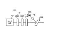
このような調光手段を備えた投射装置の光学系の一例としては、図18に示した構成が考えられる。図18に示す投射装置100の光学系は、レーザ光源101と、調光手段としての液晶アッテネータ(光減衰部)102を備えている。レーザ光源101は、RGB(R:赤、G:緑、B:青)の3色(3波長)のレーザ光を一つの光軸(同軸)に合成して出力する。
As an example of the optical system of the projection apparatus provided with such light control means, the configuration shown in FIG. 18 can be considered. The optical system of the
液晶アッテネータ102は、レーザ光源101から近い順に光路上に偏光板102A、液晶素子102B、及び偏光板102Cを備えている。偏光板102Aは、入射光から所定の偏光方位角の偏光を抽出する。液晶素子102Bは、印加される駆動電圧に応じて液晶の配向状態が制御され、出射光の偏光方位を調整する。偏光板102Cは、入射光から所定の偏光方位角の偏光を抽出する。
The
偏光板102Aと102Cのそれぞれの抽出する偏光の偏光方位角の相対角度である偏光相対角は、例えば90度に設定される。この場合、偏光板102Aと102Cは、クロス配置されると呼ぶ。
The polarization relative angle, which is the relative angle of the polarization azimuth of the polarized light extracted from each of the polarizing
このようにクロス配置した偏光板102A、102Cを用いた液晶アッテネータ102の3色光の透過率(左側の縦軸)と液晶素子102Bの駆動電圧の関係の一例を図19のグラフに示す。図19の実線(B:青)、一点鎖線(R:赤)、破線(G:緑)に示すように、駆動電圧の変化に応じて透過率(即ち減衰率)が変化するので、駆動電圧によって調光が可能となる。
A graph of FIG. 19 shows an example of the relationship between the three-color light transmittance (left vertical axis) of the
しかしながら、図19に示すように、液晶アッテネータの特性として、同じ駆動電圧であっても色(波長)によって透過率が異なる。ここで、例えば図19に示す3.5V付近の駆動電圧V1を印加した状態で液晶アッテネータ102の出射光(透過光)の量を3色で一致させるべくレーザ光源101の出射光の量を各色で調整してホワイトバランスを調整することが可能である。駆動電圧V1を印加する場合、青と緑の透過率は一致し(図19の太実線Tb/Tgで示される透過率色比が1)、赤は緑よりも透過率が低くなっている(図19の太破線Tr/Tgで示される透過率色比は1より小さい)。従って、例えば、青と緑についてはレーザ光源101の最大光量付近に調整し、赤については青と緑よりも光量を高くする。
However, as shown in FIG. 19, the transmittance of the liquid crystal attenuator varies depending on the color (wavelength) even with the same driving voltage. Here, for example, the amount of light emitted from the
しかしながら、上記調整されたレーザ光源101の各色の出力を維持したまま駆動電圧を変化させて調光しようとすると、透過率色比が変化するため色ずれが生じてホワイトバランスが崩れる。図19では具体的には、V1よりも駆動電圧を低くすると、青と緑の透過率色比Tb/Tgが次第に大きくなり、赤と緑の透過率色比Tr/Tgは次第に小さくなる。即ち、緑に対して青の光量が多くなり、赤の光量は逆に少なくなり、ホワイトバランスが崩れる。
However, if dimming is attempted by changing the driving voltage while maintaining the output of each color of the adjusted
そこで、図18に示すように、投射装置100の光学系において、液晶アッテネータ102よりも後段にハーフミラー103を配置し、集光レンズ104及び受光素子105を更に設ける。ハーフミラー103によって入射光の大部分を透過させ、残りの光を反射させる(なお、ハーフミラーという文言は、透過光と反射光に1対1とは限らない定比率で分離するものという意味で以下使用する)。そして、この反射光は集光レンズ104によって集光され、受光素子105によって受光されて光電変換される。
Therefore, as shown in FIG. 18, in the optical system of the
これにより、上記のような調光による色ずれを受光素子105によって検出することが可能となり、検出結果に基づき色ずれを補正するようにレーザ光源101の各色の出力を制御することが可能である。ここで、受光素子による光量モニタ幅は、受光素子自体の能力としての最大・最小可能受光量と、受光素子に受光させる受光量の幅によって制限を受ける。なお、最大可能受光量とは、その受光量を超えると受光素子の検出信号が飽和してしまう受光量であり、最小可能受光量とは、その受光量を下回ると受光素子の検出信号のS/N比が許容できなくなるような受光量である。
As a result, it is possible to detect the color shift due to the light control as described above by the
広い調光範囲を確保しようとする場合、受光素子に受光させる最大受光量が受光素子の最大可能受光量を超えることなく、且つ、受光素子に受光させる最小受光量が受光素子の最小可能受光量を下回って検出信号のS/N比が悪化することがないように、受光素子に受光させる受光量の幅を設定することは容易ではなかった。 When attempting to ensure a wide light control range, the maximum amount of light received by the light receiving element does not exceed the maximum possible amount of light received by the light receiving element, and the minimum amount of light received by the light receiving element is the minimum amount of light received by the light receiving element. It is not easy to set the width of the amount of received light that is received by the light receiving element so that the S / N ratio of the detection signal does not deteriorate below this value.
上記状況に鑑み、本発明は、広い調光範囲を確保した際でも受光素子に受光させる受光量の幅を適切に設定可能となる投射装置を提供することを目的とする。 In view of the above situation, an object of the present invention is to provide a projection device that can appropriately set the width of the amount of light received by the light receiving element even when a wide light control range is secured.
上記目的を達成するために本発明の投射装置は、光源部と、
前記光源部から近い順に光路上に配されて、前記光源部からの光の強度を減衰させる第1減衰部及び第2減衰部と、
第1減衰部を駆動する第1駆動部と、
第2減衰部を駆動する第2駆動部と、
第2減衰部により分配されて出射される一方の光を受光する受光素子と、を備え、
第1駆動部により第1減衰部における光の透過率を減少させ、第2駆動部により第2減衰部における前記受光素子側への出射光の分配率を上昇させる構成としている(第1の構成)。
In order to achieve the above object, the projection device of the present invention includes a light source unit,
A first attenuation unit and a second attenuation unit that are arranged on the optical path in order from the light source unit and attenuate the intensity of light from the light source unit;
A first drive unit for driving the first attenuation unit;
A second drive unit for driving the second attenuation unit;
A light receiving element that receives one light distributed and emitted by the second attenuating unit,
The first drive unit reduces the light transmittance in the first attenuation unit, and the second drive unit increases the distribution ratio of the emitted light toward the light receiving element in the second attenuation unit (first configuration). ).
このような構成によれば、第1減衰部の駆動により調光範囲を広く確保したとしても、受光素子に受光させる受光量の幅を狭くすることができる。従って、受光量が受光素子の最大可能受光量を超えることなく、且つ、受光素子の最小可能受光量を下回って検出信号のS/N比が悪化することもなくなり、適切な受光量の幅を設定することが可能となる。 According to such a configuration, the width of the amount of light received by the light receiving element can be narrowed even if a wide light control range is ensured by driving the first attenuation unit. Therefore, the received light amount does not exceed the maximum possible received light amount of the light receiving element, and the S / N ratio of the detection signal is not deteriorated below the minimum possible received light amount of the light receiving element. It becomes possible to set.
また、上記第1の構成において、第2駆動部が駆動を切替えて前記分配率を上昇させるとき、第1駆動部により第1減衰部の透過率を一旦上昇させて以降に前記駆動が切替わることとしてもよい(第2の構成)。 In the first configuration, when the second drive unit switches the drive to increase the distribution rate, the drive is switched after the first drive unit temporarily increases the transmittance of the first attenuation unit. It is good also as a thing (2nd structure).
このような構成によれば、受光素子側への光の分配率の上昇によって調光した光が急激に暗くなることを抑制できる。 According to such a structure, it can suppress that the light which was light-modulated by the raise of the distribution rate of the light to the light receiving element side becomes dark suddenly.
また、上記第1又は第2の構成において、第2駆動部は、2段階で駆動を切替えて前記分配率を上昇させることとしてもよい(第3の構成)。 In the first or second configuration, the second drive unit may switch the drive in two stages to increase the distribution rate (third configuration).
このような構成によれば、分配率が2段階のみで済むので、受光素子による受光量から第2減衰部の出射光の光量を高精度に予測可能となる。 According to such a configuration, since the distribution rate is only two steps, the amount of light emitted from the second attenuation unit can be predicted with high accuracy from the amount of light received by the light receiving element.
また、上記第1〜第3のいずれかの構成において、前記光源部は、それぞれ異なる色の光を出力する、複数の発光部を含み、
第1減衰部の有する駆動電圧と色ごとの透過率との関係を示す第1透過率特性の少なくとも一部の駆動電圧領域において、同一の駆動電圧に対して透過率が順に高くなる色の順番と、
第2減衰部の有する駆動電圧と色ごとの透過率との関係を示す第2透過率特性の少なくとも一部の駆動電圧領域において、同一の駆動電圧に対して透過率が順に高くなる色の順番と、は逆となっていることとしてもよい(第4の構成)。
Further, in any of the first to third configurations, the light source unit includes a plurality of light emitting units that output light of different colors,
The order of colors in which the transmittance increases in order with respect to the same drive voltage in at least a part of the drive voltage region of the first transmittance characteristic indicating the relationship between the drive voltage of the first attenuation unit and the transmittance for each color. When,
The order of colors in which the transmittance increases in order with respect to the same drive voltage in at least a part of the drive voltage region of the second transmittance characteristic indicating the relationship between the drive voltage of the second attenuation unit and the transmittance for each color. And may be reversed (fourth configuration).
このような構成によれば、第2減衰部の透過率を下げて分配率を上昇させたときに、第1減衰部の色ごとの透過率の差をキャンセルする方向に機能させることができる。従って、色ずれの抑制に有効となる。 According to such a configuration, when the transmittance of the second attenuator is lowered and the distribution ratio is increased, the difference in transmittance of each color of the first attenuator can be canceled. Therefore, it is effective for suppressing color misregistration.
また、上記第4の構成において、
第1減衰部は前記光源部から近い順に光路上に第1液晶素子と第1偏光部を備え、
第2減衰部は前記光源部から近い順に光路上に第2偏光部と第2液晶素子と第3偏光部を備え、
液晶素子に入射される光の偏光方位角と前記液晶素子より光路上の後段側の偏光部から出射される光の偏光方位角との相対角度を相対偏光角として、
第1減衰部における相対偏光角θ1は、45度<θ1<135度であり、
第2減衰部における相対偏光角θ2は、135度<θ2<225度であることとしてもよい(第5の構成)。
In the fourth configuration,
The first attenuating unit includes a first liquid crystal element and a first polarizing unit on the optical path in order from the light source unit.
The second attenuating unit includes a second polarizing unit, a second liquid crystal element, and a third polarizing unit on the optical path in order from the light source unit.
The relative polarization angle is the relative angle between the polarization azimuth angle of the light incident on the liquid crystal element and the polarization azimuth angle of the light emitted from the polarizing portion on the rear stage on the optical path from the liquid crystal element.
The relative polarization angle θ1 in the first attenuation unit is 45 degrees <θ1 <135 degrees,
The relative polarization angle θ2 in the second attenuation unit may be 135 degrees <θ2 <225 degrees (fifth configuration).
このような構成によれば、第1透過率特性の少なくとも一部の領域と、第2透過率特性の少なくとも一部の領域とで色ごとの透過率の大小関係が逆転している状態を実現することが可能となる。 According to such a configuration, the state in which the magnitude relationship of the transmittance for each color is reversed in at least a part of the first transmittance characteristic and at least a part of the second transmittance characteristic is realized. It becomes possible to do.
なお、第5の構成において、特に、前記相対偏光角θ1=90度であり、前記相対偏光角θ2=180度であることが望ましい(第6の構成)。 In the fifth configuration, it is particularly desirable that the relative polarization angle θ1 = 90 degrees and the relative polarization angle θ2 = 180 degrees (sixth configuration).
また、上記第1〜第6のいずれかの構成において、第1減衰部は前記光源部から近い順に光路上に第1液晶素子と第1偏光部を備え、
第2減衰部は前記光源部から近い順に光路上に第2偏光部と第2液晶素子と第3偏光部を備えることとしてもよい(第7の構成)。
In any one of the first to sixth configurations, the first attenuating unit includes a first liquid crystal element and a first polarizing unit on an optical path in order from the light source unit.
The second attenuating unit may include a second polarizing unit, a second liquid crystal element, and a third polarizing unit on the optical path in order from the light source unit (seventh configuration).
このような構成によれば、第1駆動部は第1液晶素子を駆動することにより第1減衰部の透過率を制御でき、第2駆動部は第2液晶素子を駆動することにより第3偏光部によって分配される光の分配率を制御することができる。 According to such a configuration, the first driver can control the transmittance of the first attenuator by driving the first liquid crystal element, and the second driver can drive the third polarization by driving the second liquid crystal element. The distribution ratio of the light distributed by the unit can be controlled.
また、上記第7の構成において、第2偏光部は、第1偏光部と共通の部材であることとしてもよい(第8の構成)。 In the seventh configuration, the second polarizing unit may be a member common to the first polarizing unit (eighth configuration).
このような構成によれば、部品点数を削減することができる。 According to such a configuration, the number of parts can be reduced.
また、上記第7または第8の構成において、第1減衰部は、第1液晶素子より光路上の前段側に第4偏光部を更に備えることとしてもよい(第9の構成)。 In the seventh or eighth configuration, the first attenuation unit may further include a fourth polarizing unit on the upstream side of the optical path from the first liquid crystal element (9th configuration).
このような構成によれば、第1減衰部に入射する光の偏光方位が所望のものからずれている場合でも、第4偏光部により所望の偏光方位に調整することができる。 According to such a configuration, even when the polarization azimuth of the light incident on the first attenuation unit is deviated from the desired one, the fourth polarization unit can be adjusted to the desired polarization azimuth.
また、上記第7〜第9のいずれかの構成において、第1偏光部によって分配されて出射される一方の偏光成分の光を受光する第2受光素子を更に備えることとしてもよい(第10の構成)。 Further, in any one of the seventh to ninth configurations, a second light receiving element that receives light of one polarization component distributed and emitted by the first polarization unit may be further provided (a tenth aspect). Constitution).
このような構成によれば、受光素子と第2受光素子の各受光量に基づいて第2減衰部における第3偏光部による受光素子側への光の分配率を検出することが可能となる。従って、目標の分配率となるように第2液晶素子を駆動することで分配率を制御することが可能となる。 According to such a configuration, it is possible to detect the distribution ratio of light to the light receiving element side by the third polarizing unit in the second attenuation unit based on the respective light receiving amounts of the light receiving element and the second light receiving element. Therefore, it is possible to control the distribution ratio by driving the second liquid crystal element so as to achieve the target distribution ratio.
本発明の投射装置によると、広い調光範囲を確保した際でも受光素子に受光させる受光量の幅を適切に設定可能となる。 According to the projection device of the present invention, it is possible to appropriately set the width of the amount of light received by the light receiving element even when a wide light control range is ensured.
以下に本発明の実施形態について図面を参照して説明する。ここでは、一例として、車載用のヘッドアップディスプレイ装置(HUD装置)について説明する。 Embodiments of the present invention will be described below with reference to the drawings. Here, as an example, an in-vehicle head-up display device (HUD device) will be described.
<第1実施形態>
本発明の一実施形態に係るHUD装置の概略構成を図1に示す。本実施形態のHUD装置80は、車両8に搭載されている。なお、HUD装置80は、車両に限らず、他の輸送機器(例えば船舶や航空機等)に搭載されてもよい。HUD装置80は、プロジェクタ(投射装置)1から走査レーザ光7(投射光)を車両8のフロントガラス81に向けて投射し、投射像をユーザの視野内に重ねて表示する表示装置である。なお、図1において、一点鎖線の矢印6は車両8の運転席に座っているユーザの視線を示している。
<First Embodiment>
A schematic configuration of a HUD device according to an embodiment of the present invention is shown in FIG. The HUD device 80 of this embodiment is mounted on the
図1に示すように、フロントガラス81の内面にはコンバイナ82が貼り付けられている。このコンバイナ82は、プロジェクタ1の投射像をユーザの視野内に表示するための投射部材であり、たとえばハーフミラーなどの半透過性の反射材料を用いて形成されている。コンバイナ82にプロジェクタ1から走査レーザ光7が投射されることによって、コンバイナ82の所定領域に虚像が形成される。このために、車両8の前方(すなわち視線6の方向)を見ているユーザは、車両8の前方の外界像と、プロジェクタ1から投射される投射像とを同時に視認することができる。なお、走査レーザ光7を直接的にフロントガラス81に投射させてもよい。
As shown in FIG. 1, a
フロントガラス81を通してユーザが認識する風景の一例を図2に示す。上述の通り、フロントガラス81上には、コンバイナ82が設置されている。コンバイナ82には、プロジェクタ1から投影された画像が表示される。プロジェクタ1は、図2に示すように、カーナビゲーションに関する情報(例えば経路情報)や自動車に関する情報(例えば燃費情報)などをコンバイナ82に表示する機能を有している。図2では、プロジェクタ1は、現在から1.0km地点で大阪と神戸に経路が分岐することを示す情報82Aをコンバイナ82に表示させている。図2に示すように、前方の風景中にプロジェクタ1から投影された画像が表示されるため、ユーザは車両8の運転中に視線をそらすことなく、運転に役立つ情報を取得することができる。
An example of a landscape recognized by the user through the
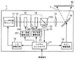
プロジェクタ1の概略構成を示すブロック図を図3に示す。図3に示すプロジェクタ1は、レーザ光源モジュール11、波長板12、第1液晶アッテネータ13、第2液晶アッテネータ14、集光レンズ15、走査ミラー部16、システムコントローラ17、LD(レーザダイオード)駆動回路18、ミラー駆動回路19、第1液晶駆動回路20、第2液晶駆動回路21、集光レンズ22、及び受光素子23を備えている。
A block diagram showing a schematic configuration of the
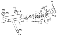
ここで、プロジェクタ1の光学系に関する構成をより具体的に示した斜視図を図4に示す。レーザ光源モジュール11(光源部の一例)は、赤色LD11A、緑色LD11B、青色LD11C、コリメータレンズ11D〜11F、合成プリズム11G、ビーム成型プリズム11H、11Iから構成される。
Here, FIG. 4 shows a perspective view more specifically showing the configuration of the optical system of the
赤色LD11A、緑色LD11B、及び青色LD11C(発光部の一例)から各々出射されて対応するコリメータレンズ11D、11E、及び11Fによって平行光にされた各光は、合成プリズム11Gに入射され、一つの光軸(同軸)である光ビームに合成される。このように、合成プリズム11Gから出射される同軸の3色からなる光ビームは、各ビーム成型プリズム11H、11Iを順に通過することで楕円偏光から円偏光に変換される。
Each light emitted from the
このようにレーザ光源モジュール11から出射された円偏光の光は波長板12によって直線偏光に変換されて、第1液晶アッテネータ13に入射される。入射された光は、第1液晶アッテネータ13(第1減衰部)、及び第2液晶アッテネータ14(第2減衰部)を順に透過することで、それぞれの透過率に応じて減衰される。
Thus, the circularly polarized light emitted from the laser
減衰された光は、集光レンズ15によって集光されつつ、偏向ミラーM(図3では不図示)によって反射されて進行方向を変えられ、走査ミラー部16に入射される。走査ミラー部16は、それぞれMEMS(Micro Electro Mechanical Systems)ミラーから成る水平走査ミラー16Aと垂直走査ミラー16Bから構成される。水平走査ミラー16Aは、入射された光の反射光を水平方向に走査する。垂直走査ミラー16Bは、入射された光の反射光を垂直方向に走査する。水平走査ミラー16Aと垂直走査ミラー16Bによって順に反射されることにより、光を2次元的に走査することができる。
The attenuated light is collected by the condensing
このように走査された光は、ウィンドウガラスW(図3では不図示)を透過してプロジェクタ1の筐体から外部へ走査レーザ光7として出射され、コンバイナ82に投射される。ウィンドウガラスWは、図4に示した光学系を収容する筐体部(プロジェクタ1の筐体内部に配される)に設けられる。
The light thus scanned passes through the window glass W (not shown in FIG. 3), is emitted from the housing of the
また、システムコントローラ17(図3)は、外部から入力される映像信号に基づいて、ミラー駆動回路19を介して走査ミラー部16の駆動を制御すると共に、LD駆動回路18を介してレーザ光源モジュール11の各色LD11A〜11Cの出力を制御する。LD駆動回路18は、駆動電流によってLDの出力を調整する。
Further, the system controller 17 (FIG. 3) controls the driving of the
また、システムコントローラ17の制御によって第1液晶駆動回路20は液晶素子13Bに駆動電圧を印加し、第2液晶駆動回路21は液晶素子14Bに駆動電圧を印加する。これにより、第1液晶アッテネータ13と第2液晶アッテネータ14の各々に透過率が設定され、これらのトータルの透過率に応じて3色のレーザ光は減衰される。即ち、調光を可能としている。
The first liquid
なお、例えば車両8に備えられた外光を検出する光センサからの検出結果に基づいてシステムコントローラ17は、第1液晶駆動回路20及び第2液晶駆動回路21を制御してもよいし、ユーザの手動設定に応じてシステムコントローラ17が制御してもよい。これにより、車両8の環境の明るさに応じて投射画像の視認性を高めることができる。
For example, the
次に、液晶アッテネータに関して詳細に説明する。第1液晶アッテネータ13のより具体的な構成を図5に示す。第1液晶アッテネータ13は、レーザ光源モジュール11から近い順に光路上に偏光板13A、液晶素子13B、及び偏光板13Cを備えている。
Next, the liquid crystal attenuator will be described in detail. A more specific configuration of the first
偏光板13Aは、入射される光から所定の偏光方位角の偏光を抽出する。液晶素子13Bは、不図示のガラス板、透明電極、配向膜、及び液晶などを有している。第1液晶駆動回路20によって透明電極間に駆動電圧が印加されることにより、液晶の配向が制御され、液晶素子13Bから出射される光の偏光方位が制御される。また、偏光板13Cは、入射される光から所定の偏光方位角の偏光を抽出する。
The
そして、偏光板13Aと偏光板13Cにより抽出される各偏光の偏光方位角の相対角度である相対偏光角は90度に設定されており、これを偏光板13Aと13Cはクロス配置されていると呼ぶ。この場合、液晶素子13Bの液晶の配向特性にもよるが、本実施形態では、図7に示す透過率特性のように、駆動電圧を上昇させるほど、偏光板13Cを透過して出射される光の量が多くなり、第1液晶アッテネータ13の透過率が大きくなるようにしている。図7に示すように、3色共にこのような特性を有する領域を持つ。
And the relative polarization angle which is the relative angle of the polarization azimuth angle of each polarization | polarized-light extracted by the
また、第2液晶アッテネータ14のより具体的な構成を図6に示す。第2液晶アッテネータ14は、レーザ光源モジュール11から近い順に光路上に偏光板14A、液晶素子14B、及びPBS(偏光ビームスプリッタ)14Cを備えている。なお、第1液晶アッテネータ13の偏光板13Cと、第2液晶アッテネータ14の偏光板14Aは、共通の部品である。液晶素子14Bの透明電極間には、第2液晶駆動回路21によって駆動電圧が印加される。
A more specific configuration of the second
偏光板13C及び液晶素子14Bの機能は第1液晶アッテネータ13の偏光板13A及び液晶素子13Bと同様である。PBS14Cは、入射された光を互いに直交する偏光成分に分解し、一方を透過させ、他方を反射させる。PBS14Cを透過した光は集光レンズ15へ導かれ、PBS14Cを反射した光は集光レンズ22に導かれて集光され、受光素子23によって受光されて光電変換される(図3、図4)。受光素子23はシステムコントローラ17に接続される。
The functions of the
システムコントローラ17は、受光素子23による受光量の検出信号に基づき、レーザ光源モジュール11における各色LD11A〜11Cの各出力を制御することで、第2液晶アッテネータ14を透過した光の色ずれを補正する。なお、色ずれの検出のタイミングについては、例えば、1フレームの投射画像を描画するときに各色LD11A〜11Cのうちいずれかを発光させた状態で、走査レーザ光7をウィンドウガラスWの外側に照射するよう走査ミラー部16を駆動することを発光色を変えながら1フレーム毎に行う。即ち、3フレーム分の描画により3色のレーザ光の色ずれを検出することができる。これにより、ユーザに視認させない態様で色ずれを検出することができる。
The
また、偏光板14Aにより抽出される光とPBS14Cにより分解されて透過する光の各偏光方位角の相対角度である相対偏光角は、180度となるように設定される。これを偏光板14AとPBS14Cはパラレル配置されると呼ぶ。この場合、液晶素子14Bの液晶の配向特性にもよるが、本実施形態では、図8に示す透過率特性のように、駆動電圧を上昇させるほど、PBS14Cを透過して出射される光の量が少なくなり、第2液晶アッテネータ14の透過率が小さくなるようにしている。図8に示すように、3色共にこのような特性を有する領域を持つ。
The relative polarization angle, which is the relative angle between the polarization azimuth angles of the light extracted by the
そして、本実施形態では、第1液晶アッテネータ13と第2液晶アッテネータ14を光路上に並べて配置することとしているので、各々の透過率を乗算した値がトータルとしての透過率となる。
In this embodiment, since the first
ここで、本実施形態で調光を行う際の第1液晶アッテネータ13及び第2液晶アッテネータ14の各駆動電圧の一例を図9に示す。図9の横軸に示す調光値は、調光の明るさを示し、値が大きいほど明るいことを示す。
Here, FIG. 9 shows an example of each driving voltage of the first
図9に示すように調光値が500から300付近までは第1液晶アッテネータの駆動電圧(実線)は曲線的に連続して単調に減少させる。このとき、図7の透過率特性により、第1液晶アッテネータ13の各色の透過率は減少する。またこのとき、図9に示すように第2液晶アッテネータ14に印加する駆動電圧(破線)は、所定の第1駆動電圧(約2.2V)で一定としている。このとき、図8の透過率特性により、第2液晶アッテネータ14の各色の透過率は、第1駆動電圧に対応する透過率で一定となる。従って、第1液晶アッテネータ13と第2液晶アッテネータ14のトータルとしての透過率は減少するので、調光値が減少する。
As shown in FIG. 9, the drive voltage (solid line) of the first liquid crystal attenuator decreases continuously and monotonously in the range of the dimming value from 500 to 300. At this time, the transmittance of each color of the first
上記のように第2液晶アッテネータ14には一定の第1駆動電圧を印加させ、それに対応した透過率で一定となるが、その透過率を1から差し引いた値が、第2液晶アッテネータ14のPBS14Cによって反射されて受光素子23側へ導かれる光の分割率(モニタ分割率)となる。図11に示すように、調光値が500から300付近まで所定のモニタ分割率で各色で一定となっている(なお、図11のモニタ分割率は50%を1と表記している)。このとき、第1液晶アッテネータ13の透過率と、モニタ分割率によって受光素子23での受光量が定まり、図10に示すように、調光値が500から300付近までは、受光素子23での各色の受光量(モニタ受光量)は単調に減少する。
As described above, a constant first driving voltage is applied to the second
一方、調光値が300付近から0までは図9に示すように、第1液晶アッテネータ13の駆動電圧は曲線的に連続して減少させると共に、第2液晶アッテネータ14の駆動電圧は、上記第1駆動電圧よりも高い所定の第2駆動電圧(約2.8V)で一定とする。このとき、第1液晶アッテネータ13の透過率は減少し、第2液晶アッテネータ14の透過率は一定となるので、トータルとしての透過率は減少するので、調光値が減少する。
On the other hand, as shown in FIG. 9, when the dimming value is from about 300 to 0, the drive voltage of the first
また第2駆動電圧は第1駆動電圧よりも高いので、図8に示す透過率特性により各色の透過率は小さくなり、モニタ分割率としては逆に図11に示すように各色で高い値で一定となる。このとき、第1液晶アッテネータ13の透過率と、モニタ分割率によって受光素子23での受光量が定まり、図10に示すように、調光値が300付近から0までは、モニタ受光量は、上記第1駆動電圧の印加時(調光値が600から300付近まで)におけるモニタ受光量の最小値から一旦上昇した状態から減少するような形となる。
Further, since the second drive voltage is higher than the first drive voltage, the transmittance of each color is reduced by the transmittance characteristic shown in FIG. 8, and the monitor division ratio is constant at a high value for each color as shown in FIG. It becomes. At this time, the amount of light received by the
このようにすることで、調光範囲を広く確保したとしても、モニタ受光量の幅を狭くすることができ、モニタ受光量が受光素子23の最大可能受光量M1(図10)を超えることなく、且つ、受光素子23の最小可能受光量M2を下回って検出信号のS/N比が悪化することもなくなり、適切なモニタ受光量の幅を設定することが可能となる。
In this way, even if a wide light control range is ensured, the width of the monitor light reception amount can be narrowed, and the monitor light reception amount does not exceed the maximum possible light reception amount M1 (FIG. 10) of the
また、図7と図8の透過率特性に示すように第1液晶アッテネータ13と第2液晶アッテネータ14で色ごとの透過率の大小関係が逆転している。具体的には、図7において駆動電圧が2V〜3.5Vの範囲の領域では、透過率の昇順に対応する色の順序は赤、緑、青の順となる。一方、図8において駆動電圧が2V〜3.5Vの範囲の領域では、透過率の昇順に対応する色の順序は青、緑、赤の順となる。即ち、両者の色の順序は逆となっている。第2駆動電圧は第1駆動電圧よりも高くしているので、図8に示す透過率特性により、第2液晶アッテネータ14での色による透過率の差が大きくなり、第1液晶アッテネータ13の透過率の色による差をキャンセルする方向に働く。
Further, as shown in the transmittance characteristics of FIGS. 7 and 8, the first
また、第2液晶アッテネータ14の駆動電圧は、第1駆動電圧と第2駆動電圧の2段階のみとしているので、モニタ分割率も2段階となり、色ずれ補正の際の第2液晶アッテネータ14の透過光量の予測精度が高くなる。
In addition, since the driving voltage of the second
なお、第1駆動電圧から第2駆動電圧への切替えの際は、第1液晶アッテネータ13の駆動電圧をそれまで減少させていたものを一旦上昇させて以降に切替えるようにする(図9に示すA部)。即ち、第1液晶アッテネータ13の透過率を上昇させる方向へ駆動することで、第2駆動電圧への切替による第2液晶アッテネータ14の透過率の減少によって調光の明るさが急減することを抑止することができる。
When switching from the first drive voltage to the second drive voltage, the drive voltage of the first
<第2実施形態>
次に、本発明の第2実施形態について説明する。本実施形態に係るプロジェクタが備える液晶アッテネータの構成を図12に示す。図12に示す液晶アッテネータ30は、第1実施形態に係るプロジェクタの構成(図3)において、第1液晶アッテネータ13及び第2液晶アッテネータ14の代わりに配置されるものである。
Second Embodiment
Next, a second embodiment of the present invention will be described. FIG. 12 shows the configuration of the liquid crystal attenuator provided in the projector according to the present embodiment. A
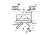
アッテネータ30は、プレート型のPBS(偏光ビームスプリッタ)31と、液晶部32と、プリズム33A及び33Bから成るPBS331と、プリズム33B及び33Cから成るPBS332と、PBS34を備えている。なお、図12に示す実線矢印は、プロジェクタの光学系における光路上の光を示す。
The
PBS31は、入射された光を互いに直交する偏光成分に分解し、一方を透過させ、他方を反射させて往路光L1として液晶部32に導く。なお、PBS31を透過した光を後述するPBS34に入射させないよう不図示の遮光部をPBS31、34の間に設ける必要がある。
The
液晶部32を透過した往路光L1は、プリズム33Bを透過してプリズム33Aに入射し、互いに直交する偏光成分に分解され、一方は透過し、他方は反射される。反射された光は、プリズム33B内を進みプリズム33Cに入射し、互いに直交する偏光成分に分解され、一方は透過し、他方は反射される。反射された光は、復路光L2として液晶部32を透過し、PBS34によって互いに直交する偏光成分に分解され、一方は透過し、他方は反射される。反射された光は、光学系の後段側(即ち集光レンズ15(図3)側)へ導かれる。一方、透過した光は、集光レンズ22へ導かれて集光され、受光素子23により受光されて光電変換される。受光素子23については第1実施形態と同様である。
The forward light L1 transmitted through the
ここで、液晶部32の構成について詳述する。液晶部32の概略斜視図を図13に、概略断面図を図14に示す。液晶部32は、ガラス板32Aと、ガラス板32Bと、液晶32Cと、配向膜323A、323B、324A、324Bと、透明電極321A、321B、322A、322Bを備えている。
Here, the configuration of the
液晶32Cの一部は、配向膜323A及び324Aによって挟まれる。液晶32C及び配向膜323A、324Aから成る部分は両側から透明電極321A及び322Aによって挟まれる。同様に、液晶32Cの別の一部は、配向膜323B及び324Bによって挟まれる。液晶32C及び配向膜323B、324Bから成る部分は両側から透明電極321B及び322Bによって挟まれる。そして、透明電極321A及び322Aによって挟まれてなる構成(第2液晶素子)と、透明電極321B及び322Bによって挟まれる構成(第1液晶素子)は、更に両側からガラス板32A及び32Bによって挟まれる。第1液晶素子に含まれる液晶と第2液晶素子に含まれる液晶は一つの空間において液晶32Cとして一体化している。
A part of the
往路光L1は透明電極321B及び322Bによって挟まれてなる構成側(第1液晶素子)を透過し、復路光L2は透明電極321A及び322Aによって挟まれてなる構成側(第2液晶素子)を透過する。第1液晶駆動回路20によって透明電極321Bと322B間に駆動電圧を印加可能であり、第2液晶駆動回路21によって透明電極321Aと322A間に駆動電圧を印加可能である。即ち、同じ液晶部32内において別々の部位を独立して駆動することができる。
The forward light L1 is transmitted through the component side (first liquid crystal element) sandwiched between the
そして、PBS31、液晶部32に含まれる第1液晶素子、及びPBS331から成る第1減衰部の相対偏光角としては90度(クロス配置)が設定され、PBS332、液晶部32に含まれる第2液晶素子、及びPBS34から成る第2減衰部の相対偏光角としては180度(パラレル配置)が設定される。従って、第1減衰部と第2減衰部はそれぞれ、例えば第1実施形態で説明した図7、図8に示す駆動電圧と透過率の関係である特性と同様の特性を有することとなる。
The relative polarization angle of the first attenuating unit composed of the
なお、PBS332を設けたのは、PBS331を反射された光の消光比が小さく、偏光方位のばらつきがあった場合でも、そのばらつきを吸収できるからである。実施形態の変形例として、プリズム33Cは設けず、プリズム33Bで全反射させた光を復路光L2としてもよい。
The PBS 332 is provided because the extinction ratio of the light reflected from the PBS 331 is small, and even when there is a variation in the polarization direction, the variation can be absorbed. As a modification of the embodiment, the
本実施形態では、調光を行う際に、例えば図9で示した第1液晶アッテネータ13の駆動電圧と同様のものを液晶部32の第1液晶素子に印加し、第2液晶アッテネータ14の駆動電圧と同様のものを第2液晶素子に印加するので、受光素子23における受光量の挙動を図10に示したものと同様とすることができる。従って、第1実施形態と同様の効果を奏することが可能である。
In the present embodiment, when dimming, for example, the same drive voltage as the first
特に本実施形態では、液晶部32における同じ液晶32Cを第1減衰部と第2減衰部で共用しているので、環境の温度変化などがあった場合でも、第1減衰部と第2減衰部において駆動電圧と透過率の関係の特性が同様に変動することになる。従って、上記のような状態変化により発生する色ずれが大きくなることを抑制できる。また、液晶部品が一つで済むので、部品コストの低減につなげることができる。
In particular, in the present embodiment, since the
<第3実施形態>
次に、本発明の第3実施形態について説明する。本実施形態に係る液晶アッテネータの構成を図15に示す。図15に示す液晶アッテネータ30自体の構成は第2実施形態(図12)と同様であり、相違点は、PBS331によって分解されて透過した光を集光する集光レンズ41と、集光された光を受光して光電変換する受光素子42を備えていることである。
<Third Embodiment>
Next, a third embodiment of the present invention will be described. FIG. 15 shows the configuration of the liquid crystal attenuator according to this embodiment. The configuration of the
このような構成によれば、受光素子42によって検出された受光量と、受光素子23によって検出された受光量に基づき、PBS34による受光素子23のモニタ分割率を検出することができる。そして、検出されたモニタ分割率が目標値となるように液晶部32の第2液晶素子の駆動電圧を制御することができる。これにより、色ずれ補正の際に受光素子23により検出された受光量から第2減衰部の出射光(PBS34の反射光)の光量を高精度に予測可能となる。なお、上記モニタ分割率の検出や第2液晶素子の駆動電圧の制御は、システムコントローラ17により行うことができる。
According to such a configuration, the monitor division ratio of the
<その他について>
上記実施形態では、第2液晶アッテネータや第2液晶素子の駆動電圧は2段階で切替えることとしたが、3段階以上で切替えてもよい。
<About others>
In the above embodiment, the driving voltage of the second liquid crystal attenuator and the second liquid crystal element is switched in two stages, but may be switched in three or more stages.
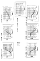
また、図16に、液晶アッテネータの相対偏光角を45度から225度まで15度ずつ変化させた場合の駆動電圧と各色透過率の関係を示す。これにより、クロス配置とパラレル配置に限らず、第1液晶アッテネータ13の相対偏光角θ1を45度<θ1<135度と設定し、第2液晶アッテネータ14の相対偏光角θ2を135度<θ2<225度と設定してもよい。
FIG. 16 shows the relationship between the drive voltage and each color transmittance when the relative polarization angle of the liquid crystal attenuator is changed by 15 degrees from 45 degrees to 225 degrees. Accordingly, the relative polarization angle θ1 of the first
また、上記実施形態において、波長板12から出射される光の偏光方位角の精度が良好である場合、第1液晶アッテネータ13の偏光板13A(第1実施形態)は備えていなくてもよい。また、液晶アッテネータ30のPBS31(第2及び第3実施形態)をミラーに置き換えた構成でもよい。
Moreover, in the said embodiment, when the precision of the polarization azimuth angle of the light radiate | emitted from the
また、液晶アッテネータの製造時に偏光板と液晶素子を回転調整できる構成を設けることが望ましい。例えば第1液晶アッテネータ13における各部品の回転調整機構の概略構成を図17に示す。図17に示すように、偏光板13AはホルダH1に保持され、液晶素子13BはホルダH2に保持され、不図示の偏光板13CはホルダH3に保持される。そして、各ホルダH1〜H3は回動可能である。偏光板13A、液晶素子13B、偏光板13Cの各部品の光出射側での光検出結果に基づいて各ホルダH1〜H3を回動させることで、上記各部品を適切な位置に回転調整することができる。なお、第2液晶アッテネータ14についても同様の回転調整機構を設けてもよい。
Further, it is desirable to provide a configuration in which the polarizing plate and the liquid crystal element can be rotationally adjusted when manufacturing the liquid crystal attenuator. For example, FIG. 17 shows a schematic configuration of a rotation adjusting mechanism for each component in the first
以上、本発明の実施形態について説明したが、本発明の趣旨の範囲内であれば、実施形態は種々の変形が可能である。 As mentioned above, although embodiment of this invention was described, if it is in the range of the meaning of this invention, embodiment may be variously deformed.
1 プロジェクタ
11 レーザ光源モジュール
11A 赤色LD
11B 緑色LD
11C 青色LD
11D〜11F コリメータレンズ
11G 合成プリズム
11H、11I ビーム成型プリズム
12 波長板
13 第1液晶アッテネータ
13A 偏光板
13B 液晶素子
13C 偏光板
14 第2液晶アッテネータ
14A 偏光板
14B 液晶素子
14C PBS(偏光ビームスプリッタ)
15 集光レンズ
16 走査ミラー部
16A 水平走査ミラー
16B 垂直走査ミラー
17 システムコントローラ
18 LD駆動回路
19 ミラー駆動回路
20 第1液晶駆動回路
21 第2液晶駆動回路
22 集光レンズ
23 受光素子
30 液晶アッテネータ
31 PBS
32 液晶部
331、332 PBS
34 PBS
41 集光レンズ
42 受光素子
W ウィンドウガラス
M 偏向ミラー
1
11B Green LD
11C Blue LD
11D to
DESCRIPTION OF
32 Liquid crystal part 331, 332 PBS
34 PBS
41 Condensing lens 42 Light receiving element W Window glass M Deflection mirror
Claims (10)
前記光源部から近い順に光路上に配されて、前記光源部からの光の強度を減衰させる第1減衰部及び第2減衰部と、
第1減衰部を駆動する第1駆動部と、
第2減衰部を駆動する第2駆動部と、
第2減衰部により分配されて出射される一方の光を受光する受光素子と、を備え、
第1駆動部により第1減衰部における光の透過率を減少させ、第2駆動部により第2減衰部における前記受光素子側への出射光の分配率を上昇させる投射装置。 A light source unit;
A first attenuation unit and a second attenuation unit that are arranged on the optical path in order from the light source unit and attenuate the intensity of light from the light source unit;
A first drive unit for driving the first attenuation unit;
A second drive unit for driving the second attenuation unit;
A light receiving element that receives one light distributed and emitted by the second attenuating unit,
A projection apparatus that reduces the light transmittance of the first attenuation unit by the first driving unit and increases the distribution ratio of the emitted light toward the light receiving element in the second attenuation unit by the second driving unit.
第1減衰部の有する駆動電圧と色ごとの透過率との関係を示す第1透過率特性の少なくとも一部の駆動電圧領域において、同一の駆動電圧に対して透過率が順に高くなる色の順番と、
第2減衰部の有する駆動電圧と色ごとの透過率との関係を示す第2透過率特性の少なくとも一部の駆動電圧領域において、同一の駆動電圧に対して透過率が順に高くなる色の順番と、は逆となっていることを特徴とする請求項1〜請求項3のいずれか1項に記載の投射装置。 The light source unit includes a plurality of light emitting units that output light of different colors,
The order of colors in which the transmittance increases in order with respect to the same drive voltage in at least a part of the drive voltage region of the first transmittance characteristic indicating the relationship between the drive voltage of the first attenuation unit and the transmittance for each color. When,
The order of colors in which the transmittance increases in order with respect to the same drive voltage in at least a part of the drive voltage region of the second transmittance characteristic indicating the relationship between the drive voltage of the second attenuation unit and the transmittance for each color. The projection apparatus according to any one of claims 1 to 3, wherein and are opposite to each other.
第2減衰部は前記光源部から近い順に光路上に第2偏光部と第2液晶素子と第3偏光部を備え、
液晶素子に入射される光の偏光方位角と前記液晶素子より光路上の後段側の偏光部から出射される光の偏光方位角との相対角度を相対偏光角として、
第1減衰部における相対偏光角θ1は、45度<θ1<135度であり、
第2減衰部における相対偏光角θ2は、135度<θ2<225度であることを特徴とする請求項4に記載の投射装置。 The first attenuating unit includes a first liquid crystal element and a first polarizing unit on the optical path in order from the light source unit.
The second attenuating unit includes a second polarizing unit, a second liquid crystal element, and a third polarizing unit on the optical path in order from the light source unit.
The relative polarization angle is the relative angle between the polarization azimuth angle of the light incident on the liquid crystal element and the polarization azimuth angle of the light emitted from the polarizing portion on the rear stage on the optical path from the liquid crystal element.
The relative polarization angle θ1 in the first attenuation unit is 45 degrees <θ1 <135 degrees,
The projection apparatus according to claim 4, wherein the relative polarization angle θ <b> 2 in the second attenuation unit is 135 degrees <θ2 <225 degrees.
第2減衰部は前記光源部から近い順に光路上に第2偏光部と第2液晶素子と第3偏光部を備えることを特徴とする請求項1〜請求項6のいずれか1項に記載の投射装置。 The first attenuating unit includes a first liquid crystal element and a first polarizing unit on the optical path in order from the light source unit.
The second attenuating unit includes a second polarizing unit, a second liquid crystal element, and a third polarizing unit on an optical path in order from the light source unit. Projection device.
Priority Applications (4)
| Application Number | Priority Date | Filing Date | Title |
|---|---|---|---|
| JP2016071931A JP2017181933A (en) | 2016-03-31 | 2016-03-31 | Projection device |
| US15/472,626 US20170290131A1 (en) | 2016-03-31 | 2017-03-29 | Projection device |
| CN201710204800.9A CN107300768A (en) | 2016-03-31 | 2017-03-30 | Projection arrangement |
| EP17164090.7A EP3226557A1 (en) | 2016-03-31 | 2017-03-31 | Projection device |
Applications Claiming Priority (1)
| Application Number | Priority Date | Filing Date | Title |
|---|---|---|---|
| JP2016071931A JP2017181933A (en) | 2016-03-31 | 2016-03-31 | Projection device |
Publications (1)
| Publication Number | Publication Date |
|---|---|
| JP2017181933A true JP2017181933A (en) | 2017-10-05 |
Family
ID=58464354
Family Applications (1)
| Application Number | Title | Priority Date | Filing Date |
|---|---|---|---|
| JP2016071931A Pending JP2017181933A (en) | 2016-03-31 | 2016-03-31 | Projection device |
Country Status (4)
| Country | Link |
|---|---|
| US (1) | US20170290131A1 (en) |
| EP (1) | EP3226557A1 (en) |
| JP (1) | JP2017181933A (en) |
| CN (1) | CN107300768A (en) |
Families Citing this family (4)
| Publication number | Priority date | Publication date | Assignee | Title |
|---|---|---|---|---|
| JP6848354B2 (en) * | 2016-11-04 | 2021-03-24 | 船井電機株式会社 | Light projection device |
| US10831029B2 (en) * | 2018-01-22 | 2020-11-10 | Microsoft Technology Licensing, Llc | Systems and methods of attenuating light in a display |
| CN108549194A (en) * | 2018-06-01 | 2018-09-18 | 深圳安麦思科技有限公司 | The control method and crystal projection screen of crystal projection screen |
| JP6734340B2 (en) * | 2018-10-01 | 2020-08-05 | 本田技研工業株式会社 | Display device, display control method, and program |
Family Cites Families (6)
| Publication number | Priority date | Publication date | Assignee | Title |
|---|---|---|---|---|
| JP2007086387A (en) | 2005-09-22 | 2007-04-05 | Nippon Seiki Co Ltd | On-vehicle display device |
| CN101399032B (en) * | 2007-09-25 | 2011-09-14 | 中强光电股份有限公司 | Display apparatus with brightness and color temperature control system and brightness and colour temperature control method |
| US20090160833A1 (en) * | 2007-12-21 | 2009-06-25 | Microvision, Inc. | Laser Projection White Balance Tracking |
| JP2014115488A (en) * | 2012-12-11 | 2014-06-26 | Funai Electric Co Ltd | Image display device |
| JP2014194493A (en) * | 2013-03-29 | 2014-10-09 | Funai Electric Co Ltd | Projector and head-up display device |
| JP2014195184A (en) * | 2013-03-29 | 2014-10-09 | Funai Electric Co Ltd | Projector and head-up display device |
-
2016
- 2016-03-31 JP JP2016071931A patent/JP2017181933A/en active Pending
-
2017
- 2017-03-29 US US15/472,626 patent/US20170290131A1/en not_active Abandoned
- 2017-03-30 CN CN201710204800.9A patent/CN107300768A/en active Pending
- 2017-03-31 EP EP17164090.7A patent/EP3226557A1/en not_active Withdrawn
Also Published As
| Publication number | Publication date |
|---|---|
| US20170290131A1 (en) | 2017-10-05 |
| EP3226557A1 (en) | 2017-10-04 |
| CN107300768A (en) | 2017-10-27 |
Similar Documents
| Publication | Publication Date | Title |
|---|---|---|
| US9134536B2 (en) | Head-up display device | |
| US10234683B2 (en) | Head-up display, and vehicle equipped with head-up display | |
| WO2015159522A1 (en) | Heads-up display and moving body equipped with heads-up display | |
| US10921587B2 (en) | Vehicle display apparatus | |
| US20160195727A1 (en) | Head-up display, and vehicle equipped with head-up display | |
| US20190137759A1 (en) | Information display apparatus | |
| TWI728094B (en) | Split exit pupil heads-up display systems and methods | |
| EP4042675B1 (en) | Laser-illuminated displays with enhanced uniformity | |
| JP2017181933A (en) | Projection device | |
| US9618745B2 (en) | Display arrangement for a motor vehicle, with an imager and an image splitter | |
| US20190317322A1 (en) | Head-up display device | |
| EP3816710A1 (en) | Head-up display device and display method therefor | |
| GB2465887A (en) | Projection device for producing a virtual image | |
| US20060215247A1 (en) | Optical system and image protection apparatus | |
| JP2018037531A (en) | Display device and head-up display device | |
| JP2017194548A (en) | Display device | |
| JP2017111223A (en) | Projection device | |
| US10324287B2 (en) | Heads-up display device | |
| US20230014232A1 (en) | Image displaying device | |
| WO2015146618A1 (en) | Laser light intensity adjustment device | |
| JP2018041046A (en) | Projection member and head-up display device | |
| WO2020031247A1 (en) | Image display device | |
| JP2016180819A (en) | Liquid crystal display device and picture display unit using the liquid crystal display device | |
| WO2018164058A1 (en) | Optical device | |
| CN117579795A (en) | Image generation module, control method thereof and vehicle-mounted vision auxiliary system |