JP2017178667A - Apparatus for producing spherical aluminum nitride particle - Google Patents
Apparatus for producing spherical aluminum nitride particle Download PDFInfo
- Publication number
- JP2017178667A JP2017178667A JP2016068074A JP2016068074A JP2017178667A JP 2017178667 A JP2017178667 A JP 2017178667A JP 2016068074 A JP2016068074 A JP 2016068074A JP 2016068074 A JP2016068074 A JP 2016068074A JP 2017178667 A JP2017178667 A JP 2017178667A
- Authority
- JP
- Japan
- Prior art keywords
- heat insulating
- aluminum nitride
- insulating case
- spherical aluminum
- applicator
- Prior art date
- Legal status (The legal status is an assumption and is not a legal conclusion. Google has not performed a legal analysis and makes no representation as to the accuracy of the status listed.)
- Granted
Links
Images


Classifications
-
- C—CHEMISTRY; METALLURGY
- C01—INORGANIC CHEMISTRY
- C01B—NON-METALLIC ELEMENTS; COMPOUNDS THEREOF; METALLOIDS OR COMPOUNDS THEREOF NOT COVERED BY SUBCLASS C01C
- C01B21/00—Nitrogen; Compounds thereof
- C01B21/06—Binary compounds of nitrogen with metals, with silicon, or with boron, or with carbon, i.e. nitrides; Compounds of nitrogen with more than one metal, silicon or boron
- C01B21/072—Binary compounds of nitrogen with metals, with silicon, or with boron, or with carbon, i.e. nitrides; Compounds of nitrogen with more than one metal, silicon or boron with aluminium
-
- C—CHEMISTRY; METALLURGY
- C01—INORGANIC CHEMISTRY
- C01F—COMPOUNDS OF THE METALS BERYLLIUM, MAGNESIUM, ALUMINIUM, CALCIUM, STRONTIUM, BARIUM, RADIUM, THORIUM, OR OF THE RARE-EARTH METALS
- C01F7/00—Compounds of aluminium
- C01F7/02—Aluminium oxide; Aluminium hydroxide; Aluminates
Landscapes
- Chemical & Material Sciences (AREA)
- Organic Chemistry (AREA)
- Inorganic Chemistry (AREA)
- Life Sciences & Earth Sciences (AREA)
- Geology (AREA)
- Furnace Details (AREA)
- Physical Or Chemical Processes And Apparatus (AREA)
- Ceramic Products (AREA)
Abstract
Description
本発明は、球状窒化アルミニウム粒子製造装置に関する。 The present invention relates to an apparatus for producing spherical aluminum nitride particles.
球状アルミナ(Al2O3)粒子は、熱伝導性に優れたフィラーや放熱用シートの部材として、半導体基板等の電子デバイスに広く使用されている。熱伝導性をさらに高めるために、カーボンを付着させた球状アルミナ粒子を窒素雰囲気中でマイクロ波により1400〜1700℃に加熱して窒化することによって、窒化アルミニウム改質層を備えたアルミナ粒子を製造するためのマイクロ波加熱装置が知られている(特許文献1、図1)。該装置は、カーボンを付着させた球状アルミナ粒子を保持するアルミナ坩堝の全周囲を取り囲むように、セラミックファイバー製断熱ボードで形成された断熱性ケースを備え、該断熱性ケースの天板部に、アルミナ坩堝内に窒素ガスを供給するためのアルミナパイプが挿入された構造となっている。 Spherical alumina (Al 2 O 3 ) particles are widely used in electronic devices such as semiconductor substrates as fillers having excellent thermal conductivity and members for heat dissipation sheets. To further improve thermal conductivity, spherical alumina particles with carbon attached are heated to 1400-1700 ° C in a nitrogen atmosphere and nitrided to produce alumina particles with a modified aluminum nitride layer A microwave heating apparatus for this purpose is known (Patent Document 1, FIG. 1). The apparatus includes a heat insulating case formed of a ceramic fiber heat insulating board so as to surround the entire periphery of the alumina crucible holding the spherical alumina particles to which carbon is adhered, and the top plate portion of the heat insulating case includes: An alumina pipe for supplying nitrogen gas is inserted into the alumina crucible.
しかし、上記装置を用いた場合、断熱性ケースの外側表面の一部が黒焦げになって溶損することが認められた。これは、マイクロ波による加熱により、カーボンとして使用される活性炭やカーボンブラック中の不純物から発生した熱分解ガス(不純物ガスとも呼ぶ)が、断熱性ケースの外側表面で固化し、断熱性ケースに付着した固化物がマイクロ波により再加熱され炭化したことによるものと考えられる。断熱ボードの外側でマイクロ波が吸収されてしまうと、アルミナ粒子に到達するマイクロ波のエネルギーが低下するので窒化の反応効率も低下する。 However, when the above apparatus was used, it was recognized that a part of the outer surface of the heat insulating case was charred and melted. This is because pyrolysis gas (also called impurity gas) generated from impurities in activated carbon or carbon black used as carbon solidifies on the outer surface of the heat insulating case and adheres to the heat insulating case. This is probably because the solidified product was reheated and carbonized by microwaves. If microwaves are absorbed outside the heat insulation board, the energy of the microwaves reaching the alumina particles is reduced, so that the nitriding reaction efficiency is also reduced.
本発明は、上記のような問題に鑑みてなされたものであり、断熱性ケースの溶損や窒化効率の低下を抑制できる、球状窒化アルミニウム粒子製造装置を提供することを目的とする。 This invention is made | formed in view of the above problems, and it aims at providing the spherical aluminum nitride particle manufacturing apparatus which can suppress the melting loss of a heat insulation case and the fall of nitriding efficiency.
本発明の球状窒化アルミニウム粒子製造装置は、マイクロ波発振器を備えるアプリケーター内で、球状アルミナ粒子と炭素系材料粉末とを含む混合物を、窒素雰囲気中でマイクロ波を照射して、該球状アルミナ粒子の少なくとも一部を窒化して球状窒化アルミニウム粒子を製造する、球状窒化アルミニウム粒子製造装置であって、前記アプリケーター内に設けられて前記球状アルミナ粒子と炭素系材料粉末とを含む混合物を収容する、非密閉性の断熱性ケースと、前記球状窒化アルミニウム粒子の製造時における窒化反応の過程で生じる気体を該断熱性ケースの内側から該アプリケーターの外側へと排出する排気管と、を備えることを特徴とする。 The apparatus for producing spherical aluminum nitride particles according to the present invention irradiates a mixture containing spherical alumina particles and a carbon-based material powder with microwaves in a nitrogen atmosphere in an applicator equipped with a microwave oscillator. A spherical aluminum nitride particle production apparatus for producing spherical aluminum nitride particles by nitriding at least a part thereof, wherein the non-spherical aluminum nitride particle production apparatus is provided in the applicator and contains a mixture containing the spherical alumina particles and the carbonaceous material powder. A sealing heat insulating case, and an exhaust pipe for discharging a gas generated in the process of nitriding during the production of the spherical aluminum nitride particles from the inside of the heat insulating case to the outside of the applicator. To do.
本発明の球状窒化アルミニウム粒子製造装置によれば、窒化の過程で発生するガスが断熱性ケースからアプリケーター外へと速やかに排出されるので、窒化の過程で発生するガスに含まれた不純物ガスが断熱性ケースの外側表面で固化・付着し難くなり、付着箇所での意図しないマイクロ波吸収による加熱が発生することを防止でき、かくして、断熱性ケースの溶損や窒化効率の低下を抑制できる。 According to the spherical aluminum nitride particle producing apparatus of the present invention, the gas generated in the nitriding process is quickly discharged from the heat insulating case to the outside of the applicator, so that the impurity gas contained in the gas generated in the nitriding process It becomes difficult to solidify and adhere to the outer surface of the heat insulating case, and it is possible to prevent heating due to unintentional microwave absorption at the attached portion, and thus it is possible to suppress melting damage and reduction in nitriding efficiency of the heat insulating case.
本発明において、球状窒化アルミニウム粒子とは、主に、フィラーとしての性能を確保するために球状アルミナ粒子の表面近傍を窒化することで改質し、球状アルミナ粒子の表面を窒化アルミニウムとなしたものをいうが、それ以外にも、窒化反応が進み、球状アルミナ粒子全体が、球状窒化アルミニウムと化したものも含んでいる。 In the present invention, the spherical aluminum nitride particles are mainly modified by nitriding the vicinity of the surface of the spherical alumina particles to ensure the performance as a filler, and the surface of the spherical alumina particles is changed to aluminum nitride. However, other than that, the nitriding reaction proceeds, and the spherical alumina particles as a whole are converted into spherical aluminum nitride.
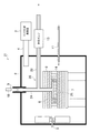
図1は、本発明の球状窒化アルミニウム粒子製造装置の一態様の断面模式図である。球状窒化アルミニウム粒子製造装置1は、アプリケーター(加熱炉)2と、マイクロ波発振器3とを備える。アプリケーター2には、アプリケーター2内の電磁界分布を均一化するためのスターラー5と、被加熱体が載置される載置台7とが内部に設けられており、マイクロ波発振器3からのマイクロ波を当該アプリケーター2内へと導く導波路4が側壁の所定位置に設けられている。
FIG. 1 is a schematic cross-sectional view of one embodiment of the spherical aluminum nitride particle production apparatus of the present invention. The spherical aluminum nitride particle manufacturing apparatus 1 includes an applicator (heating furnace) 2 and a microwave oscillator 3. The
本発明の球状窒化アルミニウム粒子製造装置1は、アプリケーター2内の載置台7上に、球状アルミナ粒子と炭素系材料粉体とを含む混合物6(以下「混合物6」という場合がある)を収容するための、非密閉性の断熱性ケース8を備える。ここで「非密閉性」とは、断熱性ケース8において窒素ガス等の気体の出入りが可能であることを意味する。ここで、アプリケーター2には、窒素ガス供給管11が側壁の所定位置に設けられているが、窒素ガス供給管11は断熱性ケース8の内側にまで挿入されている必要はなく、窒化ガスを吐出する供給口がアプリケーター2内の任意の箇所に備えられる。これによりアプリケーター2内全体を反応に必要な窒素ガスで満たすことができる。窒素ガス供給管11は、図示しないボンベ等の窒素ガス貯留部と接続されており、当該窒素ガス貯留部内の窒素ガスをアプリケーター2内に供給する。
The spherical aluminum nitride particle production apparatus 1 of the present invention accommodates a mixture 6 (hereinafter also referred to as “
本態様では、断熱性ケース8は所定の厚みの断熱ボード又は断熱ファイバーからなる多層構造体であり、原料アルミナの窒化に必要な窒素ガスは断熱ボード自体の孔や、断熱ボード間の隙間又は断熱ファイバーの間を通って、断熱性ケース8内へと入り、及び断熱性ケース8から出ることができる。混合物6は、断熱性ケース8の底板上に直接置いてもよいが、好ましくは、混合物6を、例えばマイクロ波透過性の高純度アルミナ、高純度シリカ、高純度マグネシア、トリジマイト、サイアロン、窒化アルミニウム等からなるこう鉢14、坩堝、又は皿等の容器に入れる。断熱性ケース8はマイクロ波透過性の繊維状のアルミナ、シリカ、及びムライトの少なくも一種を含む断熱材から形成することができる。
In this embodiment, the
アプリケーター2には排気管12が設けられている。排気管12は、混合物6と断熱性ケース8の天板部との間の空間に、吸気口を配置しており、当該空間から断熱性ケース8の側面を貫通してアプリケーター2の外側へと延びる。排気管12は、断熱性ケース8内で発生される、炭素系材料粉体中の不純物による熱分解ガス(不純物ガス)を、吸気口を介してアプリケーター2の外側へと排出する。これにより球状窒化アルミニウム粒子製造装置1では、窒化の過程で発生するガスに含まれた不純物ガスが断熱性ケース8の外側表面まで到達する前に不純物ガスを当該断熱性ケース8内からアプリケーター2外へと排出できることから、不純物ガスが断熱性ケース8の外側表面で固化・付着し難くなり、付着箇所での意図しないマイクロ波吸収による加熱が発生することを防止できる。かくして、球状窒化アルミニウム粒子製造装置1では、断熱性ケース8の溶損や窒化効率の低下を抑制できる。この際、窒化反応により生成される一酸化炭素ガスも反応系外へと排出されるので、窒化反応が促進される。
The
また、排気管12には、出口に排気ポンプ13が接続されている。排気ポンプ13は、断熱性ケース8内における空間内の気体を、排気管12を介して排出し、断熱性ケース8内を当該断熱性ケース8外よりも負圧に維持し得る。これにより、排気ポンプ13は、断熱性ケース8内において窒化の過程で発生するガスが、断熱性ケース8内から排出されることを促すと共に、窒素ガスの断熱性ケース8内への流入を促す。なお、図1では、窒素ガス供給管11により窒素ガスが混合物6の上側から供給される構成としたが、窒素ガス供給管11の供給口の位置についてはこれに限定されず、例えば窒素ガス供給管により混合物6の下側から窒素ガスを供給するようにしてもよい。なお、窒素ガス供給管11及び排気管12は、例えばアルミナ等のマイクロ波透過性の材料で構成することができる。
An
なお、この実施の形態の場合、断熱性ケース8及びこう鉢14は、内部の混合物6の温度を監視するために、天板部に測温用の開口15を有している。また、アプリケーター2の天板部には、所定位置に石英等でなる赤外線透過性の窓部9が設けられており、窓部9の外側に表面温度計10が設けられている。表面温度計10は、混合物6から射出される赤外線を、開口15及び窓部9を介して検出し、混合物6の表面温度へと換算する。表面温度計10にて測定した混合物6の表面温度は、アルミナ粒子の窒化の度合いの指標となり得る。
In the case of this embodiment, the
次に、他の実施の形態による球状窒化アルミニウム粒子製造装置について以下説明する。図1との対応部分に同一符号を付した図2は本発明の球状窒化アルミニウム粒子製造装置の他の態様の断面模式図である。この球状窒化アルミニウム粒子製造装置21は、排気管26が第一の管24及び第二の管22から構成されている点と、該第一の管24が、原料を充填する断熱性ケース8の所定位置からアプリケーター2に設けられた窓部9まで連通し、表面温度測定用の管を兼ねる構造となっている点とにおいて、上述した図1における球状窒化アルミニウム粒子製造装置1と相違している。
Next, a spherical aluminum nitride particle manufacturing apparatus according to another embodiment will be described below. FIG. 2, in which the same reference numerals are assigned to the parts corresponding to those in FIG. In this spherical aluminum nitride
排気管26を構成する第一の管24は、こう鉢14及び断熱性ケース8の天板部に形成された開口25と一体化しており、当該開口25から、アプリケーター2の天板部に向けて直線的に延び、端部がアプリケーター2内の所定位置に配置されている。第一の管24の途中には、第一の管24と連通し、かつ第一の管24の長手方向とは異なる方向に向けてアプリケーター2の外側へと延びた第二の管22が設けられている。なお、この実施の形態の場合では、断熱性ケース8の天板部に形成された開口25からアプリケーター2の天板部に向けて鉛直に第一の管24が延びており、当該第一の管24の側壁からアプリケーター2の側壁に向けて第二の管22が延び、アプリケーター2の側壁を第二の管22が貫通するように設けられている。
The
第二の管22は、出口に排気ポンプ13が設けられており、当該排気ポンプ13によって第二の管22内の気体が排出され得る。これにより、断熱性ケース8内における空間内の気体は、第一の管24から第二の管22を経由してアプリケーター2外へと排出され得る。第一の管24は、アプリケーター2の天板部に窓部9を設定するための窓設置部まで端部が到達しており、上部がアプリケーター2の天板部における窓設置部と一体形成されており、窒化の過程で断熱性ケース8内において発生したガスが第一の管24から漏れ出ることなく、第二の管22へと誘導し得る。
The
ここで、第一の管24は、断熱性ケース8内における混合物6の表面から窓部9までを直線的に結ぶように配置されていることから、窓部9の外側に設けられた表面温度計10によって、混合物6から射出される赤外線を、窓部9、第一の管24を介して検出し得る。
Here, since the
以上の構成において、この球状窒化アルミニウム粒子製造装置21でも、窒化の過程で発生するガスに含まれた不純物ガスが断熱性ケース8の外側表面まで到達する前に、排気管26により不純物ガスを当該断熱性ケース8内からアプリケーター2外へと排出できることから、不純物ガスが断熱性ケース8の外側表面で固化・付着し難くなり、付着箇所での意図しないマイクロ波吸収による加熱が発生することを防止できる。かくして、球状窒化アルミニウム粒子製造装置21でも、断熱性ケース8の溶損や窒化効率の低下を抑制できる。
In the above configuration, the spherical aluminum nitride
また、球状窒化アルミニウム粒子製造装置21では、断熱性ケース8の開口25に第一の管24を設け、当該第一の管24から第二の管22を介して、断熱性ケース8内で発生したガスを排気するようにしたことにより、図1に示すように、第一の管24を設けずに断熱性ケース8の開口がアプリケーター2内と連通している場合に比べて、断熱性ケース8内で発生したガスを排気管26によって確実に排気させることができる。
Further, in the spherical aluminum nitride
さらに、球状窒化アルミニウム粒子製造装置21では、第二の管22を介して第一の管24内の気体も排気することから、第一の管24の末端に配置された窓部9からのガス漏れも防止できる。
Furthermore, since the spherical aluminum nitride
因みに、第二の管22が第一の管24から分岐する位置は、断熱性ケース8の天板部からアプリケーター2の天板部までの間であれば種々の位置としてよい。なお、第一の管24、第二の管22はアルミナ等のマイクロ波透過性の材料で構成することができる。第一の管24の内側にアルミニウムを蒸着する等して赤外線の反射率を高めてもよい。また、本態様では、第二の管22が第一の管24に対して垂直に配置されているが、これに限定されず所望の角度であってよい。
Incidentally, the position where the 2nd pipe |
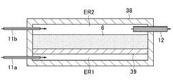
次に、他の実施の形態による断熱性ケースについて以下説明する。図3は、図1及び図2に示す断熱性ケース8とは異なる態様の断熱性ケースの断面模式図である。断熱性ケース38は、混合物6を保持するための保持板39を、断熱性ケース38の底板から所定の高さの位置に備えている。保持板39は、多孔質等の窒素ガスを透過(通過)させる構造となっており、マイクロ波を吸収しづらい、アルミナ、シリカ、サイアロン、トリジマイト、マグネシア、窒化アルミニウム等の耐熱性セラミック素材から形成されている。なお、断熱性ケース38には、図示ない蓋部により内部の保持板39を外部に露出可能の構成されており、当該保持板39上に混合物6を保持し得る。
Next, a heat insulating case according to another embodiment will be described below. FIG. 3 is a schematic cross-sectional view of a heat insulating case having a mode different from that of the
断熱性ケース38には、保持板39と底板との間の側壁に一の窒素ガス供給管11aが設けられており、保持板39と底板との間の下側空間ER1に一の窒素ガス供給管11aによって窒化ガスが供給され得る。また、断熱性ケース38には、天板部と混合物6との間の側壁に、他の窒素ガス供給管11bと排気管12とが設けられている。これにより、他の窒素ガス供給管11bは、天板部と混合物6との間の上側空間ER2に窒化ガスを供給し、排気管12は、天板部と混合物6との間の上側空間ER2内のガスを排気し得る。
The
なお、上述した実施の形態においては、一の窒素ガス供給管11a及び他の窒素ガス供給管11bの2つを設けるようにした場合について述べたが、本発明はこれに限らず、一の窒素ガス供給管11a及び他の窒素ガス供給管11bのいずれか一方のみを設けるようにしてもよい。ここで、下側空間ER1に窒素ガス供給管11aを設け、上側空間ER2に排気管12を設けた場合(即ち、他の窒素ガス供給管11bを設けない場合)には、下側空間ER1、保持板39、混合物6、上側空間ER2、及び排気管12に向けて流れる気流を形成できることから、混合物6において窒化反応を促進させることができるとともに、供給管が設けられた側に対し、混合物6の反対側に窒素ガスが到達しにくいという問題を解決し、工業的に一定以上の分量の窒化アルミニウムを焼成するプロセスにおける焼成ムラを抑制することが可能となる。特に、この実施の形態の場合、断熱材ケース38には、下側空間ER1における一の側壁に窒素ガス供給管11aを設け、上側空間ER2において当該一側壁と対向する他の側壁に排気管12を設け、窒素ガス供給管11aと排気管12とを対向するように配置したことにより、一の側壁側から他の側壁側に向けて窒化ガスを流すことができ、混合物6全体の窒化反応を促進させるこができる。
In the above-described embodiment, the case where two of the one nitrogen
保持板39を備える位置は、混合物6の量に応じて、断熱性ケース38の底板と天板部との間であれば任意の位置であってよい。また、保持板39は断熱性ケース38の側面に固定されている必要はなく、混合物6の量に応じて、可動式としてもよい。或いは、保持板39に複数の脚部を付して、自立性の台として構成してもよい。断熱性ケース38は、例えば前記のマイクロ波を吸収しづらいアルミナ等の耐熱性セラミック材料から構成することができる。
The position including the holding
以上の構成においても、上述した実施の形態と同様に、排気管12により不純物ガスを断熱性ケース38内からアプリケーター2外へと排出できることから、不純物ガスが断熱性ケース38の外側表面で固化し難くなり、その分、断熱性ケース38の溶損や窒化効率の低下を抑制できる。
Also in the above configuration, since the impurity gas can be discharged from the
次に、図3に示した断熱性ケース38とは構成が異なる他の実施の形態による断熱性ケースについて以下説明する。図4は、断熱性ケースの他の態様の断面模式図であり、窒素ガス等の気体の出入りが可能な複数の開口48dを備える断熱性ケース48の一例を示す。断熱性ケース48は、蓋部48aと本体部48bとを備え、蓋部48aと本体部48bとの境界に沿って開口48dが形成されている。
Next, a heat insulating case according to another embodiment having a configuration different from that of the
この実施の形態の場合、蓋部48aは、本体部48bの縁部と接する縁部48cに凹部が形成された構成を有しており、当該凹部に対して、本体部48bの縁部が接することで本体部48bとの境界に開口48dを形成し得る。因みに、排気管12は、図3の態様と同様に、断熱性ケース48内における図示しない混合物6の上側に備えられる。図4では、蓋部48aの縁部48cに開口48dを形成する凹部を形成した場合について述べたが、本発明はこれに限らず、本体部48bの縁部に開口48dを形成する凹部を形成してもよい。また、開口48dを形成する形状としては、凹部と凸部が交互に規則的に配置されている必要はなく、凹部や凸部が不規則に配置された構成であってもよい。また、開口48dは四辺状でなくてもよく、円形等のその他種々の形状であってもよく、さらに、開口48dとして、蓋部48a及び/又は本体部48bの側壁に貫通孔を設けてもよい。更に、開口48dは図3の上部空間ER2に接する側面に設けてもよく、又は、図3の下部空間ER1に接する側面に設けても良い。
In the case of this embodiment, the
本態様においても、断熱性ケース48は、例えば前記のマイクロ波を吸収しづらいアルミナ等の耐火性セラミック材料から構成することができる。
Also in this embodiment, the
以上の構成においても、上述した実施の形態と同様に、排気管12により不純物ガスを断熱性ケース48内からアプリケーター2外へと排出できることから、不純物ガスが断熱性ケース48の外側表面で固化し難くなり、その分、断熱性ケース48の溶損や窒化効率の低下を抑制できる。
Also in the above configuration, the impurity gas can be discharged from the inside of the
因みに、上述した各実施の形態においては、断熱性ケース38、48(蓋部48a及び本体部48b)も、アルミナ、シリカ、及びムライトの少なくも一種を含む断熱材から形成することができる。図4の態様においても、断熱性ケース48を多孔質体で構成することによって、窒素ガスの取り込み効率がさらに向上される。なお、他の実施の形態としては、例えば、図4に示すような開口48dを、図3に示した断熱性ケース38に設けてもよく、図1〜図4の構成を適宜選択的に組み合わせた構成としてもよい。また、図3及び図4における排気管12にも排気ポンプ13が設けられている。
Incidentally, in each embodiment mentioned above, the
本発明において、球状窒化アルミニウム粒子を得るために用いる球状アルミナ粒子は真球状又は略真球状であればよい。球状アルミナ粒子は、例えば、レーザ粒度分布測定機(CILAS製CILAS-920)を用いて質量基準で求めた50質量%平均粒子径(D50)で5〜150μmであることが望ましい。これは、製造した球状窒化アルミニウム粒子を樹脂と混合し、フィラーとした場合に必要な熱伝導特性を得やすい粒子径であることによる。 In the present invention, the spherical alumina particles used for obtaining the spherical aluminum nitride particles may be spherical or substantially spherical. The spherical alumina particles are desirably, for example, 5 to 150 μm in terms of a 50 mass% average particle diameter (D50) determined on a mass basis using a laser particle size distribution analyzer (CILAS-920 manufactured by CILAS). This is because the produced spherical aluminum nitride particles are mixed with a resin to obtain a heat conduction characteristic required when the filler is used as a filler.
球状アルミナ粒子は、アルミナ粉末を球状に造粒することにより得られたものを使うことができる。球状アルミナ粉末は、例えばアルコキシド法、バイヤー法、アンモニウム明ばん熱分解法、又はアンモニウムドーソナイト熱分解法等によって得ることができる。造粒法としては、湿式撹拌造粒法、スプレードライ法等があるが、好ましくはスプレードライ法により造粒した粒子が使用される。スプレードライ法としては、ノズル法、ディスク法等の何れの方式であってもよい。 As the spherical alumina particles, those obtained by granulating alumina powder into a spherical shape can be used. The spherical alumina powder can be obtained, for example, by an alkoxide method, a Bayer method, an ammonium alum pyrolysis method, or an ammonium dosonite pyrolysis method. Examples of the granulation method include a wet stirring granulation method and a spray drying method. Preferably, particles granulated by the spray drying method are used. The spray drying method may be any method such as a nozzle method or a disk method.
炭素系材料粉末としては、例えば黒鉛、カーボンブラック、アセチレンブラック、無定形炭素等の粉末が挙げられ、天然由来であっても工業的に製造されたものであってもよい。好ましくは製造後の窒化アルミニウムの絶縁性能に影響を与えないために、金属含有率が1質量%以下、好ましくは金属含有率が0.1質量%以下であるものが望ましい。炭素系粉末は混合原料である球状アルミナ粒子を被覆するように存在することが望ましく、球状アルミナ粒子の上記平均径以下の平均粒径を有することがより望ましい。 Examples of the carbon-based material powder include powders of graphite, carbon black, acetylene black, amorphous carbon, and the like, which may be naturally derived or industrially produced. Preferably, the metal content is 1% by mass or less, and preferably the metal content is 0.1% by mass or less so as not to affect the insulation performance of the aluminum nitride after production. The carbon-based powder is desirably present so as to cover the spherical alumina particles that are the mixed raw material, and more preferably has an average particle diameter equal to or smaller than the average diameter of the spherical alumina particles.
球状アルミナ粒子と炭素系材料粉体とを含む混合物は、球状アルミナ粒子と炭素系材料粉体を乾式でボールミル等により混合することで調製することができる。混合の際に、例えば水、アルコール等の液状分散媒を加えてもよいが、乾燥する手間がかかるので、好ましくは乾式で混合する。混合比は、下記反応式に基づくAl2O3/3C化学量論比の0.5倍以下程度であることが望ましい。
Al2O3 + 3C +N2 → 2AlN +3CO
The mixture containing the spherical alumina particles and the carbon-based material powder can be prepared by mixing the spherical alumina particles and the carbon-based material powder in a dry manner with a ball mill or the like. In mixing, for example, a liquid dispersion medium such as water or alcohol may be added. However, since it takes time to dry, it is preferably mixed dry. The mixing ratio is desirably about 0.5 times or less of the Al 2 O 3 / 3C stoichiometric ratio based on the following reaction formula.
Al 2 O 3 + 3C + N 2 → 2AlN + 3CO
1、21 球状窒化アルミニウム粒子製造装置
2 アプリケーター(加熱炉)
3 マイクロ波発振器
4 導波路
5 スターラー
6 球状アルミナ粒子と炭素系材料粉体とを含む混合物
7 載置台
8、38、48 断熱性ケース
9 窓部
12、26 排気管
13 排気ポンプ
22 第二の管
24 第一の管
39 保持板
1,21 Spherical aluminum nitride
DESCRIPTION OF SYMBOLS 3
Claims (8)
前記アプリケーター内に設けられて前記球状アルミナ粒子と炭素系材料粉末とを含む混合物を収容する、非密閉性の断熱性ケースと、
前記球状窒化アルミニウム粒子の製造時における窒化反応の過程で生じる気体を該断熱性ケースの内側から該アプリケーターの外側へと排出する排気管と、
を備えることを特徴とする、球状窒化アルミニウム粒子製造装置。 In an applicator equipped with a microwave oscillator, a mixture containing spherical alumina particles and carbon-based material powder is irradiated with microwaves in a nitrogen atmosphere, and at least a part of the spherical alumina particles is nitrided to form spherical aluminum nitride particles. An apparatus for producing spherical aluminum nitride particles,
A non-sealing heat-insulating case provided in the applicator and containing a mixture containing the spherical alumina particles and the carbon-based material powder;
An exhaust pipe for discharging a gas generated in the process of nitriding during the production of the spherical aluminum nitride particles from the inside of the heat insulating case to the outside of the applicator;
An apparatus for producing spherical aluminum nitride particles, comprising:
前記第一の管は、前記アプリケーターの天板部に設けられた窓部と連通することを特徴とする、請求項1又は2記載の球状窒化アルミニウム粒子製造装置。 The exhaust pipe communicates with the first pipe extending from the opening formed in the top plate portion of the heat insulating case toward the top plate portion of the applicator, to the outside of the applicator. A second tube extending,
3. The spherical aluminum nitride particle producing apparatus according to claim 1, wherein the first tube communicates with a window portion provided in a top plate portion of the applicator.
前記保持板が前記窒素ガスを透過させる構造からなり、
前記窒素ガス供給管の供給口が該保持板の下側に配置されることを特徴とする、請求項5記載の球状窒化アルミニウム粒子製造装置。 The heat insulating case includes a holding plate for holding the mixture;
The holding plate has a structure that allows the nitrogen gas to pass therethrough,
6. The spherical aluminum nitride particle producing apparatus according to claim 5, wherein a supply port of the nitrogen gas supply pipe is disposed below the holding plate.
Priority Applications (3)
| Application Number | Priority Date | Filing Date | Title |
|---|---|---|---|
| JP2016068074A JP6725107B2 (en) | 2016-03-30 | 2016-03-30 | Spherical aluminum nitride particle manufacturing equipment |
| PCT/JP2017/013220 WO2017170857A1 (en) | 2016-03-30 | 2017-03-30 | Device for manufacturing spherical aluminum nitride particles |
| TW106110910A TW201806851A (en) | 2016-03-30 | 2017-03-30 | Apparatus for producing spherical aluminium nitride particle |
Applications Claiming Priority (1)
| Application Number | Priority Date | Filing Date | Title |
|---|---|---|---|
| JP2016068074A JP6725107B2 (en) | 2016-03-30 | 2016-03-30 | Spherical aluminum nitride particle manufacturing equipment |
Publications (2)
| Publication Number | Publication Date |
|---|---|
| JP2017178667A true JP2017178667A (en) | 2017-10-05 |
| JP6725107B2 JP6725107B2 (en) | 2020-07-15 |
Family
ID=59965960
Family Applications (1)
| Application Number | Title | Priority Date | Filing Date |
|---|---|---|---|
| JP2016068074A Active JP6725107B2 (en) | 2016-03-30 | 2016-03-30 | Spherical aluminum nitride particle manufacturing equipment |
Country Status (3)
| Country | Link |
|---|---|
| JP (1) | JP6725107B2 (en) |
| TW (1) | TW201806851A (en) |
| WO (1) | WO2017170857A1 (en) |
Cited By (1)
| Publication number | Priority date | Publication date | Assignee | Title |
|---|---|---|---|---|
| KR20200024592A (en) * | 2018-08-28 | 2020-03-09 | 주식회사 엘지화학 | Manufacturing method of spherical aluminum nitride powder |
Families Citing this family (1)
| Publication number | Priority date | Publication date | Assignee | Title |
|---|---|---|---|---|
| CN113387337A (en) * | 2021-05-25 | 2021-09-14 | 宝鸡泉兴钛业股份有限公司 | Equipment and process method for preparing high-titanium-nitride powder by titanium powder nitriding method |
Citations (6)
| Publication number | Priority date | Publication date | Assignee | Title |
|---|---|---|---|---|
| JP2002234711A (en) * | 2001-02-02 | 2002-08-23 | Ibaraki Kenkyusho:Kk | Method for producing aluminum nitride and aluminum nitride |
| JP2010536711A (en) * | 2007-08-31 | 2010-12-02 | ジェイピーエス マイクロテック カンパニー リミテッド | Method for producing flaky aluminum oxide using microwaves |
| JP2011219309A (en) * | 2010-04-09 | 2011-11-04 | Nippon Steel Corp | Method for producing alumina particle with aln modified layer, and modified alumina powder |
| JP2012041254A (en) * | 2010-08-23 | 2012-03-01 | Tohoku Univ | Aluminum nitride wire, method for producing the same, and apparatus for producing aluminum nitride wire |
| JP2012041253A (en) * | 2010-08-23 | 2012-03-01 | Tohoku Univ | Aluminum nitride-based particle, method for producing the same, and apparatus for producing aluminum nitride-based particle |
| WO2014123247A1 (en) * | 2013-02-08 | 2014-08-14 | 株式会社トクヤマ | Aluminum nitride powder |
-
2016
- 2016-03-30 JP JP2016068074A patent/JP6725107B2/en active Active
-
2017
- 2017-03-30 TW TW106110910A patent/TW201806851A/en unknown
- 2017-03-30 WO PCT/JP2017/013220 patent/WO2017170857A1/en active Application Filing
Patent Citations (6)
| Publication number | Priority date | Publication date | Assignee | Title |
|---|---|---|---|---|
| JP2002234711A (en) * | 2001-02-02 | 2002-08-23 | Ibaraki Kenkyusho:Kk | Method for producing aluminum nitride and aluminum nitride |
| JP2010536711A (en) * | 2007-08-31 | 2010-12-02 | ジェイピーエス マイクロテック カンパニー リミテッド | Method for producing flaky aluminum oxide using microwaves |
| JP2011219309A (en) * | 2010-04-09 | 2011-11-04 | Nippon Steel Corp | Method for producing alumina particle with aln modified layer, and modified alumina powder |
| JP2012041254A (en) * | 2010-08-23 | 2012-03-01 | Tohoku Univ | Aluminum nitride wire, method for producing the same, and apparatus for producing aluminum nitride wire |
| JP2012041253A (en) * | 2010-08-23 | 2012-03-01 | Tohoku Univ | Aluminum nitride-based particle, method for producing the same, and apparatus for producing aluminum nitride-based particle |
| WO2014123247A1 (en) * | 2013-02-08 | 2014-08-14 | 株式会社トクヤマ | Aluminum nitride powder |
Cited By (2)
| Publication number | Priority date | Publication date | Assignee | Title |
|---|---|---|---|---|
| KR20200024592A (en) * | 2018-08-28 | 2020-03-09 | 주식회사 엘지화학 | Manufacturing method of spherical aluminum nitride powder |
| KR102584925B1 (en) | 2018-08-28 | 2023-10-04 | 주식회사 엘지화학 | Manufacturing method of spherical aluminum nitride powder |
Also Published As
| Publication number | Publication date |
|---|---|
| TW201806851A (en) | 2018-03-01 |
| WO2017170857A1 (en) | 2017-10-05 |
| JP6725107B2 (en) | 2020-07-15 |
Similar Documents
| Publication | Publication Date | Title |
|---|---|---|
| WO2017170857A1 (en) | Device for manufacturing spherical aluminum nitride particles | |
| CN107935634A (en) | A kind of refractory metal compound high-temperature oxidation resistant coating and preparation method thereof | |
| JP5451998B2 (en) | Method for producing powdery alumina precursor | |
| CN105948775A (en) | Preparation method of high-temperature-resistant and oxidation-resistant lightweight carbon/carbon thermal insulation material | |
| CN101817684B (en) | Method for coating h-BN coating on surface of porous Si3N4 substrate | |
| CN103936436B (en) | A kind of yttrium stable zirconium oxide refractory product of gradient function | |
| JP2000272973A (en) | Microwave heating furnace and baking of refractory containing organic binder | |
| Duan et al. | Oxidation and ablation behavior of a ceramizable resin matrix composite based on carbon fiber/phenolic resin | |
| WO2017170856A1 (en) | Method for manufacturing spherical aluminum nitride particles, and device for manufacturing spherical aluminum nitride particles | |
| JP5677912B2 (en) | Lining structure of molten metal container | |
| CN103922814B (en) | A kind of zirconia refractory product of composite structure | |
| TWM454528U (en) | Graphite manufacturing apparatus | |
| CN106187203B (en) | A kind of method and products thereof that aluminium nitride powder is prepared based on aluminium carbide | |
| Qiu et al. | Thermal shock resistant 3D printed ceramics reinforced with MgAl2O4 shell structure | |
| JP6476794B2 (en) | Manufacturing method of heat insulating plate and manufacturing apparatus thereof, and vacuum heat insulating material and manufacturing method thereof | |
| KR20120086986A (en) | CVD equipments for the uniformity coating of spherical form | |
| CN105801127A (en) | Method for preparing high-thermal-conductivity aluminum nitride ceramic substrate for integrated circuit package | |
| CN109400128A (en) | A kind of aluminum-carbon refractory material of the powder containing pyrophillite and preparation method thereof | |
| CN208012373U (en) | A kind of crystalline ceramics microwave sintering machine | |
| Kim et al. | Preparation of granule powders for thermal spray coating by utilization of pyrophyllite minerals | |
| CN104445316B (en) | A kind of preparation method of nano alumina material, goods and application | |
| JPH03288639A (en) | Heat insulating material | |
| JP7356298B2 (en) | Nitriding reactor | |
| JPS61236671A (en) | Manufacture of silicon nitride coating refractories | |
| JPH05124884A (en) | Carbon fiber/carbon composite material |
Legal Events
| Date | Code | Title | Description |
|---|---|---|---|
| A711 | Notification of change in applicant |
Free format text: JAPANESE INTERMEDIATE CODE: A712 Effective date: 20181029 |
|
| A621 | Written request for application examination |
Free format text: JAPANESE INTERMEDIATE CODE: A621 Effective date: 20190322 |
|
| A131 | Notification of reasons for refusal |
Free format text: JAPANESE INTERMEDIATE CODE: A131 Effective date: 20191105 |
|
| A521 | Request for written amendment filed |
Free format text: JAPANESE INTERMEDIATE CODE: A523 Effective date: 20191225 |
|
| A131 | Notification of reasons for refusal |
Free format text: JAPANESE INTERMEDIATE CODE: A131 Effective date: 20200303 |
|
| A521 | Request for written amendment filed |
Free format text: JAPANESE INTERMEDIATE CODE: A523 Effective date: 20200403 |
|
| TRDD | Decision of grant or rejection written | ||
| A01 | Written decision to grant a patent or to grant a registration (utility model) |
Free format text: JAPANESE INTERMEDIATE CODE: A01 Effective date: 20200526 |
|
| A61 | First payment of annual fees (during grant procedure) |
Free format text: JAPANESE INTERMEDIATE CODE: A61 Effective date: 20200616 |
|
| R150 | Certificate of patent or registration of utility model |
Ref document number: 6725107 Country of ref document: JP Free format text: JAPANESE INTERMEDIATE CODE: R150 |
|
| R250 | Receipt of annual fees |
Free format text: JAPANESE INTERMEDIATE CODE: R250 |