JP2017177662A - Head unit and liquid discharge device - Google Patents
Head unit and liquid discharge device Download PDFInfo
- Publication number
- JP2017177662A JP2017177662A JP2016070943A JP2016070943A JP2017177662A JP 2017177662 A JP2017177662 A JP 2017177662A JP 2016070943 A JP2016070943 A JP 2016070943A JP 2016070943 A JP2016070943 A JP 2016070943A JP 2017177662 A JP2017177662 A JP 2017177662A
- Authority
- JP
- Japan
- Prior art keywords
- nozzle
- head unit
- wall portion
- chips
- disposed
- Prior art date
- Legal status (The legal status is an assumption and is not a legal conclusion. Google has not performed a legal analysis and makes no representation as to the accuracy of the status listed.)
- Granted
Links
- 239000007788 liquid Substances 0.000 title claims description 12
- 238000012986 modification Methods 0.000 description 11
- 230000004048 modification Effects 0.000 description 11
- 239000000853 adhesive Substances 0.000 description 8
- 230000001070 adhesive effect Effects 0.000 description 8
- 239000003086 colorant Substances 0.000 description 5
- 238000001746 injection moulding Methods 0.000 description 3
- 238000000034 method Methods 0.000 description 3
- 238000003825 pressing Methods 0.000 description 3
- 238000004080 punching Methods 0.000 description 3
- 230000007423 decrease Effects 0.000 description 2
- 230000003247 decreasing effect Effects 0.000 description 2
- 239000000463 material Substances 0.000 description 2
- 238000000465 moulding Methods 0.000 description 2
- 239000000758 substrate Substances 0.000 description 2
- 238000004891 communication Methods 0.000 description 1
- 230000008602 contraction Effects 0.000 description 1
- 230000006866 deterioration Effects 0.000 description 1
- 239000006185 dispersion Substances 0.000 description 1
- 230000000694 effects Effects 0.000 description 1
- 239000002184 metal Substances 0.000 description 1
- 230000002093 peripheral effect Effects 0.000 description 1
- 229920005989 resin Polymers 0.000 description 1
- 239000011347 resin Substances 0.000 description 1
- 238000000926 separation method Methods 0.000 description 1
- 229920003002 synthetic resin Polymers 0.000 description 1
- 239000000057 synthetic resin Substances 0.000 description 1
Images


Classifications
-
- B—PERFORMING OPERATIONS; TRANSPORTING
- B41—PRINTING; LINING MACHINES; TYPEWRITERS; STAMPS
- B41J—TYPEWRITERS; SELECTIVE PRINTING MECHANISMS, i.e. MECHANISMS PRINTING OTHERWISE THAN FROM A FORME; CORRECTION OF TYPOGRAPHICAL ERRORS
- B41J2/00—Typewriters or selective printing mechanisms characterised by the printing or marking process for which they are designed
- B41J2/005—Typewriters or selective printing mechanisms characterised by the printing or marking process for which they are designed characterised by bringing liquid or particles selectively into contact with a printing material
- B41J2/01—Ink jet
- B41J2/135—Nozzles
- B41J2/145—Arrangement thereof
- B41J2/155—Arrangement thereof for line printing
-
- B—PERFORMING OPERATIONS; TRANSPORTING
- B41—PRINTING; LINING MACHINES; TYPEWRITERS; STAMPS
- B41J—TYPEWRITERS; SELECTIVE PRINTING MECHANISMS, i.e. MECHANISMS PRINTING OTHERWISE THAN FROM A FORME; CORRECTION OF TYPOGRAPHICAL ERRORS
- B41J2/00—Typewriters or selective printing mechanisms characterised by the printing or marking process for which they are designed
- B41J2/005—Typewriters or selective printing mechanisms characterised by the printing or marking process for which they are designed characterised by bringing liquid or particles selectively into contact with a printing material
- B41J2/01—Ink jet
- B41J2/21—Ink jet for multi-colour printing
- B41J2/2132—Print quality control characterised by dot disposition, e.g. for reducing white stripes or banding
- B41J2/2146—Print quality control characterised by dot disposition, e.g. for reducing white stripes or banding for line print heads
-
- B—PERFORMING OPERATIONS; TRANSPORTING
- B41—PRINTING; LINING MACHINES; TYPEWRITERS; STAMPS
- B41J—TYPEWRITERS; SELECTIVE PRINTING MECHANISMS, i.e. MECHANISMS PRINTING OTHERWISE THAN FROM A FORME; CORRECTION OF TYPOGRAPHICAL ERRORS
- B41J2/00—Typewriters or selective printing mechanisms characterised by the printing or marking process for which they are designed
- B41J2/005—Typewriters or selective printing mechanisms characterised by the printing or marking process for which they are designed characterised by bringing liquid or particles selectively into contact with a printing material
- B41J2/01—Ink jet
- B41J2/135—Nozzles
- B41J2/145—Arrangement thereof
-
- B—PERFORMING OPERATIONS; TRANSPORTING
- B41—PRINTING; LINING MACHINES; TYPEWRITERS; STAMPS
- B41J—TYPEWRITERS; SELECTIVE PRINTING MECHANISMS, i.e. MECHANISMS PRINTING OTHERWISE THAN FROM A FORME; CORRECTION OF TYPOGRAPHICAL ERRORS
- B41J2202/00—Embodiments of or processes related to ink-jet or thermal heads
- B41J2202/01—Embodiments of or processes related to ink-jet heads
- B41J2202/19—Assembling head units
-
- B—PERFORMING OPERATIONS; TRANSPORTING
- B41—PRINTING; LINING MACHINES; TYPEWRITERS; STAMPS
- B41J—TYPEWRITERS; SELECTIVE PRINTING MECHANISMS, i.e. MECHANISMS PRINTING OTHERWISE THAN FROM A FORME; CORRECTION OF TYPOGRAPHICAL ERRORS
- B41J2202/00—Embodiments of or processes related to ink-jet or thermal heads
- B41J2202/01—Embodiments of or processes related to ink-jet heads
- B41J2202/20—Modules
Abstract
Description
本発明は、ヘッドユニット、及び、複数のヘッドユニットを備えた液体吐出装置に関する。 The present invention relates to a head unit and a liquid ejection apparatus including a plurality of head units.
従来から、液体吐出装置として、複数のヘッドユニットが被記録媒体の幅方向に並べられて構成された、ライン型の吐出ヘッドが知られている。 Conventionally, as a liquid ejection apparatus, a line-type ejection head in which a plurality of head units are arranged in the width direction of a recording medium is known.
特許文献1のヘッドは、被記録媒体の幅方向に並ぶ複数のヘッドユニット(インクジェット式記録ヘッド)を有する。各ヘッドユニットは、被記録媒体の幅方向に並ぶ複数のノズルチップ(ヘッド本体)と、複数のノズルチップを保持する保持部材と、複数のノズルチップの吐出面側に配置された固定板を有する。
The head of
各ノズルチップの複数のノズルは、被記録媒体の搬送方向及び幅方向とそれぞれ交差する、斜めの方向に配列されている。複数のノズルチップの上面は、保持部材の裏面に接着剤で接合されている。また、複数のノズルチップの間での吐出面の高さばらつきを、ノズルチップと保持部材の間の接着剤によって吸収することが開示されている。 The plurality of nozzles of each nozzle chip are arranged in an oblique direction intersecting with the recording medium conveyance direction and the width direction, respectively. The upper surfaces of the plurality of nozzle chips are bonded to the back surface of the holding member with an adhesive. Further, it is disclosed that the height variation of the ejection surface among a plurality of nozzle chips is absorbed by an adhesive between the nozzle chip and the holding member.
特許文献2のヘッドも、被記録媒体の幅方向に並ぶ複数のヘッドユニットを有するものである。但し、この特許文献2におけるヘッドユニットの配置は、被記録媒体の搬送方向においてヘッドユニットの位置が交互にずれた配置、いわゆる千鳥配置である。
The head of
特許文献2のヘッドは、さらに、複数のヘッドユニットの吐出面側に配置された、複数のヘッドユニットに共通の固定板と、複数のヘッドユニットに対して固定板と反対側に配置されたケース部材を有する。
The head of
ケース部材は、各ヘッドユニットを取り囲むように配置された壁部を有し、壁部の固定板側の端面には複数の凸部(突起部)が形成されている。これら複数の凸部が固定板に押し付けられることで、固定板が複数の凸部の先端位置に倣う。これにより、固定板の平坦度が高まり、複数のヘッドユニット間での吐出面の高さばらつきが抑えられる。 The case member has a wall portion disposed so as to surround each head unit, and a plurality of convex portions (projections) are formed on the end surface of the wall portion on the fixing plate side. When the plurality of convex portions are pressed against the fixed plate, the fixed plate follows the tip positions of the plurality of convex portions. As a result, the flatness of the fixed plate is increased, and variations in the height of the ejection surface among the plurality of head units can be suppressed.
特許文献1のヘッドでは、各ヘッドユニットにおいて、複数のノズルチップ間の吐出面のばらつきを接着剤で吸収するとしているが、接着剤のみで上記ばらつきを小さく抑えることは現実には難しい。
In the head of
一方、特許文献2のヘッドでは、各ヘッドユニットを取り囲むように配置された、ケース部材の複数の凸部が固定板に押し付けられることで、固定板の平坦化が図られている。 但し、特許文献2で開示された技術を、特許文献1の構成に適用しようとした場合には、次のような問題が起こり得る。
On the other hand, in the head of
特許文献1のヘッドでは、各ヘッドユニットのノズルチップにおいて、複数のノズルが、被記録媒体の搬送方向と幅方向の両方と交差する、斜めの方向に配列されている。この構成において、前記幅方向に隣接する2つのヘッドユニット間でノズルを繋ぐ、あるいは、2つのヘッドユニットのノズル同士を一部重ねる観点から、2つのヘッドユニットの間での、ノズルチップ間の距離は極力小さくすることが望ましい。
In the head of
しかし、特許文献2のように、各ヘッドユニットを取り囲むように壁部が存在する構成では、各ヘッドユニットに対して被記録媒体の幅方向の外側に壁部が配置される。従って、特許文献2の構成をそのまま特許文献1のヘッドに適用すると、隣接する2つのヘッドユニットの間に壁部が配置されることになり、2つのヘッドユニットの間でのノズルチップ間距離が長くなってしまう。
However, as in
本発明の目的は、隣接するヘッドユニットの間でのノズルチップ間距離を大きくすることなく、複数のノズルチップの吐出面の高さばらつきを確実に抑えることである。 An object of the present invention is to reliably suppress the height variation of the ejection surfaces of a plurality of nozzle chips without increasing the distance between nozzle chips between adjacent head units.
本発明のヘッドユニットは、第1方向に並んで配置され、且つ、それぞれが、吐出面に平行な方向であって前記第1方向及び前記第1方向と直交する第2方向とそれぞれ交差する、第3方向に配列されたノズルを有する複数のノズルチップと、前記複数のノズルチップを前記吐出面と反対側から保持するホルダと、前記複数のノズルチップの前記吐出面側に配置され、前記複数のノズルチップが固定される固定板と、を有し、
前記ホルダは、前記複数のノズルチップに対して前記第2方向における外側に配置された第1壁部を有し、前記第1方向において前記ノズルチップが前記ホルダから露出し、前記第1壁部の前記固定板側の端面に、前記固定板に当接する複数の第1凸部が形成されていることを特徴とするものである。
The head units of the present invention are arranged side by side in the first direction, and each intersects the first direction and the second direction orthogonal to the first direction, each being a direction parallel to the ejection surface. A plurality of nozzle chips having nozzles arranged in a third direction; a holder for holding the plurality of nozzle chips from a side opposite to the ejection surface; and the plurality of nozzle chips disposed on the ejection surface side of the plurality of nozzle chips, A fixed plate to which the nozzle tip is fixed,
The holder has a first wall portion arranged on the outer side in the second direction with respect to the plurality of nozzle tips, the nozzle tip is exposed from the holder in the first direction, and the first wall portion A plurality of first protrusions that are in contact with the fixed plate are formed on an end surface of the fixed plate.
また、本発明の液体吐出装置は、第1方向に並ぶ複数のヘッドユニットを備え、
各ヘッドユニットは、吐出面に平行で、且つ、前記第1方向及び前記第1方向と直交する第2方向とそれぞれ交差する、第3方向に配列されたノズルを有し、前記第1方向に並んで配置された複数のノズルチップと、前記複数のノズルチップを前記吐出面と反対側から保持するホルダと、前記複数のノズルチップの前記吐出面側に配置され、前記複数のノズルチップが固定される固定板と、を有し、
前記ホルダは、前記複数のノズルチップに対して前記第2方向における外側に配置された第1壁部を有し、前記第1方向において前記ノズルチップが前記ホルダから露出し、前記第1壁部の前記固定板側の端面に、前記固定板に当接する複数の第1凸部が形成されていることを特徴とするものである。
The liquid ejection device of the present invention includes a plurality of head units arranged in the first direction,
Each head unit has nozzles arranged in a third direction that are parallel to the ejection surface and intersect each of the first direction and the second direction orthogonal to the first direction. A plurality of nozzle chips arranged side by side, a holder for holding the plurality of nozzle chips from the side opposite to the ejection surface, and disposed on the ejection surface side of the plurality of nozzle chips, the plurality of nozzle chips being fixed A fixed plate, and
The holder has a first wall portion arranged on the outer side in the second direction with respect to the plurality of nozzle tips, the nozzle tip is exposed from the holder in the first direction, and the first wall portion A plurality of first protrusions that are in contact with the fixed plate are formed on an end surface of the fixed plate.
次に、本発明の実施の形態について説明する。尚、以下の説明では、図1の記録用紙100の搬送方向を、プリンタ1の前後方向と定義する。また、記録用紙100の幅方向をプリンタ1の左右方向と定義する。さらに、前後方向及び左右方向と直交する、図1の紙面垂直方向をプリンタ1の上下方向と定義する。
Next, an embodiment of the present invention will be described. In the following description, the conveyance direction of the
<プリンタの概略構成>
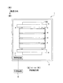
図1に示すように、プリンタ1は、筐体2内に収容されたプラテン3、4つのインクジェットヘッド4、2つの搬送ローラ5,6、及び、制御装置7等を備えている。
<Schematic configuration of printer>
As shown in FIG. 1, the
プラテン3の上面には、記録用紙100が載置される。4つのインクジェットヘッド4は、プラテン3の上方において、搬送方向に並べて配置されている。各インクジェットヘッド4は、用紙幅方向に並ぶ複数のノズル15(図2参照)を有する、いわゆる、ラインタイプのヘッドである。このインクジェットヘッド4には、図示しないインクタンクからインクが供給される。尚、4つのインクジェットヘッド4には、異なる色のインクが供給される。つまり、4つのインクジェットヘッド4は、それぞれ異なる色のインクを吐出するものである。
A
図1に示すように、2つの搬送ローラ5,6は、プラテン3に対して後側と前側にそれぞれ配置されている。2つの搬送ローラ5,6は、図示しないモータによってそれぞれ駆動され、プラテン3上の記録用紙100を前方へ搬送する。
As shown in FIG. 1, the two
制御装置7は、CPU(Central Processing Unit)、ROM(Read Only Memory)、RAM(Random Access Memory)、及び、各種制御回路を含むASIC(Application Specific Integrated Circuit)を備える。また、制御装置7は、PC等の外部装置9とデータ通信可能に接続されており、外部装置9から送られた印刷データに基づいて、プリンタ1の各部を制御する。
The
より具体的には、制御装置7は、搬送ローラ5,6を駆動するモータを制御して、2つの搬送ローラ5,6に記録用紙100を搬送方向に搬送させる。また、これとともに、制御装置7は、4つのインクジェットヘッド4を制御して記録用紙100に向けてインクを吐出させる。これにより、記録用紙100に画像が印刷される。
More specifically, the
<インクジェットヘッドの詳細構成>
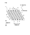
次に、インクジェットヘッド4について詳細に説明する。図2に示すように、インクジェットヘッド4は、左右方向に並んだ状態でユニット保持板10に取り付けられた、4つのヘッドユニット11を備えている。4つのヘッドユニット11は、後述するホルダ14に形成されたインク供給孔23(図3参照)において、共通のインクタンク(図示省略)とそれぞれ接続される。即ち、4つのヘッドユニット11は、それぞれ同じ色のインクを吐出するものである。
<Detailed configuration of inkjet head>
Next, the
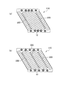
図3〜図5に示すように、各ヘッドユニット11は、6つのノズルチップ12と、固定板13と、ホルダ14を備えている。各ノズルチップ12の平面形状は矩形であり、ノズルチップ12の下面にはその長手方向に沿って複数のノズル15が配列されている。つまり、ノズルチップ12の下面は、複数のノズル15からインクが吐出される吐出面16となる。
As shown in FIGS. 3 to 5, each
ここで、一般的なラインヘッドであれば、各ノズルチップ12は、その長手方向が用紙幅方向と平行となるように配置される。これに対して、本実施形態では、各ノズルチップ12は、その長手方向が、用紙幅方向である左右方向、及び、搬送方向である前後方向とそれぞれ交差する、いわば斜めの姿勢で配置されている。それぞれ斜めの姿勢で配置された6つのノズルチップ12は、左右方向に並んで配置されている。各ヘッドユニット11内の左右方向に隣接する2つのノズルチップ12の間では、一部のノズル15が搬送方向において重なっている。図3に示すように、各ノズルチップ12の長手方向中央部には、後述するホルダ14のインク供給孔と連通する供給口17が形成されている。
Here, if it is a general line head, each
ノズルチップ12の、左右方向に対する傾き角度θは特に限定されないが、この角度θを大きくするほど、左右方向におけるノズル15の配列間隔が小さくなり、ヘッド4の解像度を高くすることができる。図4に示すように、各ノズルチップ12のチップ長手方向におけるノズル15の配列ピッチをPとしたときに、例えば、角度θを60度とすれば、用紙幅方向におけるノズル15の配列ピッチはP/2となる。逆に、角度θを小さくすると、左右方向におけるノズル15の配列間隔は大きくなる(解像度が小さくなる)が、隣接するノズルチップ12の間での、搬送方向においてノズル15が重なる部分の幅(重なり幅W1)を大きくできる。尚、上記の重なり幅W1が小さいと、2つのノズルチップ12の間でのノズル15の繋ぎ目が目立ちやすくなることから、画品質の向上という観点からは、重なり幅W1は大きいことが好ましい。
The inclination angle θ of the
尚、ノズルチップ12の平面形状は矩形であり、ノズルチップ12の長手方向の端部の端面12aは、ノズルチップ12の長手方向と直交する方向(チップ短手方向)と平行である。上記のような矩形のノズルチップ12は、他の形式のインクジェットヘッドにも流用しやすく汎用性が高い。例えば、本実施形態のノズルチップ12を、その長手方向が記録用紙の搬送方向と平行となるように配置することで、用紙幅方向に移動させながらインクを吐出する、いわゆるシリアルタイプのインクジェットヘッドを構成することができる。その際に、ノズルチップ12の平面形状が矩形、即ち、チップ長手方向の端面12aがチップ短手方向と平行であると、シリアルタイプのインクジェットヘッドの、搬送方向のサイズを小さくすることができる。
The planar shape of the
図2に示すように、隣接する2つのヘッドユニット11にそれぞれ属する2つのノズルチップ12の間においても、一部のノズル15が搬送方向において重なっている。4つのヘッドユニット11をそれぞれ構成するノズル15が用紙幅方向において繋がって配置されることで、ラインタイプのヘッドが実現されている。尚、本実施形態では、1つのヘッドユニット11内の2つのノズルチップ12間でのノズル15の重なり幅W1と、隣接する2つのヘッドユニット11にそれぞれ属する2つのノズルチップ12間での重なり幅W2とが等しくなっている。例えば、重なり幅W1=W2=4.2225mmとする。また、ノズルチップ12の傾きθ=60度、チップ長手方向におけるノズル15の配列ピッチP=84.7μm(300dpi)とすると、ノズル15の用紙幅方向における配列ピッチは、P/2=42.35μmとなる。この場合に、重なり幅W1(W2)にて重なるノズル15の数は、W1/(P/2)であるからほぼ100個となり、各ノズルチップ12の全ノズル15の約1/4が重なることになる。
As shown in FIG. 2, some
固定板13は、金属等で形成された板部材である。固定板13は、6つのノズルチップ12の下側、即ち、吐出面16側に配置されている。固定板13には、6つのノズルチップ12の吐出面16をそれぞれ露出させるための、6つの穴13aが形成されている。図6(b)に示すように、各ノズルチップ12は、固定板13の上面の、対応する穴13aの周囲領域に接着剤18で接合されている。尚、6つの穴13aは、打ち抜き加工によって形成される。この打ち抜き加工時に、穴13aの縁部が少し変形するために、固定板13の下面の平面度が大きくなる。尚、平面度とは、理想的な平面に対するズレの程度を示す指標であり、平面度が小さいほど、対象となる面は理想的な平面に近づく。この打ち抜き加工による平面度の増加(悪化)は、次述のホルダ14に形成された凸部31,32によって矯正される。
The fixed
ホルダ14は、例えば、合成樹脂材料の射出成型によって製造される。ホルダ14は、6つのノズルチップ12を上から覆うように配置されて、6つのノズルチップ12を保持する。図3〜図5に示すように、ホルダ14は、天井部20と、天井部から下方に延びる2つの第1壁部21と、及び、同じく天井部から下方に延びる5つの第2壁部22を有する。
The
天井部20は、6つのノズルチップ12と上下に重なるように配置されている。天井部20には、1つのインク供給孔23が形成されている。図6(b)に示すように、天井部20の内面は、6つのノズルチップ12の上面と接着剤24で接合されている。図示は省略するが、天井部20の内部には、インク供給孔23に接続されたインク流路が形成されている。このインク流路は、6つのノズルチップ12の供給口17と連通する。図示しないインクタンクから各ヘッドユニット11のインク供給孔23に供給されたインクは、天井部20内に形成されたインク流路によって、6つのノズルチップ12の供給口17に分配される。つまり、6つのノズルチップ12のノズル15は同じ種類のインクを吐出する。
The
2つの第1壁部21は、天井部20の前後両端部からそれぞれ下方に延びており、6つのノズルチップ12のチップ長手方向の端面12aを前後方向から覆っている。尚、図3、図6(b)に示すように、天井部20の左右両端部には壁部は設けられておらず、ノズルチップ12は、左右方向においてはホルダ14から露出している。
The two
上述したように、ノズルチップ12の長手方向端部の端面12aの方向は、チップ長手方向と直交している。つまり、上記端面12aは、前後方向及び左右方向とそれぞれ交差する面である。一方で、第1壁部21の前後方向における内側部分は、6つのノズルチップ12の前記端面12aに対応した傾斜面を有する6つの凹部21aが形成されており、各凹部21aにノズルチップ12の端部が嵌め込まれている。別の言い方をすれば、6つのノズルチップ12に対して前後方向外側に配置された第1壁部21の、内側部分の一部21bが、2つのノズルチップ12の端部の間に入り込んでいる。
As described above, the direction of the
図5、図6(a)に示すように、各第1壁部21の下面には、左右方向に間隔を空けて5つの第1凸部31が形成されている。第1凸部31は、例えば、半球状の外形を有し、成型により第1壁部21と一体的に形成されている。また、第1凸部31は、その一部分が、第1壁部21の前記2つのノズルチップ12の端部の間に入り込んだ部分21bに配置されている。図6(a)に示すように、各第1壁部21の下面は、5つの第1凸部31が固定板13の上面に押し付けられて当接した状態で、接着剤24によって固定板13と接合されている。
As shown in FIGS. 5 and 6A, five first
各第2壁部22は、左右方向に隣接する2つのノズルチップ12の間に配置され、ノズルチップ12に沿ってその長手方向に延びている。第2壁部22の下面には、チップ長手方向に間隔を空けて複数の第2凸部32が形成されている。上記の第1凸部31と同様、この第2凸部32も、例えば、半球状の外形を有し、成型により第2壁部22と一体的に形成されている。但し、図5、図6に示すように、第1凸部31の大きさは、第2凸部32よりも大きくなっている。具体的には、第1凸部31の直径が0.6mm、第2凸部32の直径が0.3mmである。
Each
また、第1凸部31、第2凸部32の形状は、上記の半球形には限られない。固定板13と接着されることから、先端に平坦な面を有する形状、例えば、円柱形状や円錐台形状であるのがよい。
Moreover, the shape of the 1st
また、6つのノズルチップ12の間には、合計5箇所の隙間が存在する。それら5箇所の隙間の全てに第2壁部22が配置され、5つの第2壁部22の全てに第2凸部32が形成されている。この構成では、左右方向における中央側の4つのノズルチップ12については、各々のノズルチップ12に対して、左右両側に2つの第2壁部22が配置されることになる。その上で、ノズルチップ12の一方側の第2壁部22の第2凸部32と、他方側の第2壁部22の第2凸部32とが、チップ短手方向においてノズルチップ12を挟んで向かい合うように配置されている。即ち、ノズルチップ12に対して一方側の第2凸部32と他方側の第2凸部32が、チップ短手方向と平行な同一直線L上に配置されている。
In addition, there are a total of five gaps between the six
上記のように、第1凸部31と第2凸部32は、ホルダ14の成型時に同時に形成される。ここで、ホルダ14の射出成型において、樹脂材料の伸縮等の要因により、ホルダ14の下面全域にわたって高精度に高さ位置を揃えることは難しい。これに対して、ホルダ14の下面に複数の凸部31,32が設けられた構成では、凸部31,32の高さを適切に調整することにより、固定板13の高さ位置を均一化することが可能である。尚、上述した特許文献2にも記載されているように、凸部31,32の高さ調整は、例えば、射出成型に使用する金型をネジ等の調整部材を用いて調整することにより行うことができる。このように、ホルダ14の下面に形成された複数の凸部31,32をそれぞれ固定板13に接触させる構成を採用することにより、ホルダ14の下面全域を固定板13に直接接触させる場合と比べて、固定板13の平面度を小さく抑えることができる。
As described above, the first
図6(b)に示すように、各第2壁部22の下面は、複数の第2凸部32が固定板13の上面に押し付けられて当接した状態で、接着剤24によって固定板13と接合されている。
As shown in FIG. 6B, the lower surface of each
以上説明したように、本実施形態のヘッドユニット11においては、6つのノズルチップ12に対して前後方向における外側に、ホルダ14の2つの第1壁部21がそれぞれ配置されている。第1壁部21には5つの第1凸部31が形成され、第1壁部21は、5つの第1凸部31が固定板13に当接した状態で接合される。この構成により、各ヘッドユニット11において固定板13の高精度な平面度を実現でき、4つのヘッドユニット11間での固定板13の高さばらつきも抑えられる。
As described above, in the
一方で、6つのノズルチップ12に対して、左右方向における外側には壁部がなく、端側のノズルチップ12がホルダ14から露出している。尚、「ノズルチップ12がホルダ14から露出している」とは、左右両端のノズルチップ12が、左右方向においてホルダ14によって覆われていないことを示す。この構成では、左右方向に4つのヘッドユニット11が並べられたときに、隣接する2つのヘッドユニット11のノズルチップ12同士を近づけて配置でき、2つのヘッドユニット11間でのノズルチップ12の距離を小さくすることが可能となる。
On the other hand, with respect to the six
第1壁部21の一部分が、隣接する2つのノズルチップ12の間に入り込んでいる。これは、第1壁部21の内側部分に、6つのノズルチップ12にそれぞれ対応する6つの凹部21aが形成された構成であるとも言える。この構成では、組立時に各ノズルチップ12を凹部21aに嵌め込むことで、第1壁部21に対する位置決めが容易になる。
A part of the
さらに、第1壁部21の、隣接するノズルチップ12の端部の間に入り込んだ部分21bに、第1凸部31の一部が配置されている。これにより、第1凸部31とノズルチップ12との距離が小さくなり、ノズルチップ12の近傍で固定板13の高さ位置を決めることができる。
Furthermore, a part of the first
また、本実施形態では、左右方向に隣接する2つのノズルチップ12の間に、ホルダ14の第2壁部22が配置されている。第2壁部22には複数の第2凸部32が形成され、第2壁部22は、複数の第2凸部32が固定板13に当接した状態で接合される。この構成により、ノズルチップ12の間においても、固定板13の高さ位置が確実に決められる。
Moreover, in this embodiment, the
尚、第2壁部22は、左右方向に隣接するノズルチップ12の間に配置されるものであるが、この第2壁部22が存在することによって、2つのノズルチップ12の間の離間距離が大きくなる。上記離間距離が大きくなるほど2つのノズルチップ12間でのノズル15の重なり幅W1が小さくなり、さらには、2つのノズルチップ12のノズル15を連続させること自体難しくなる。この点、本実施形態では、1つのヘッドユニット11の6つのノズルチップ12は、全て同じ種類のインクを吐出させるものである。この場合は、2つのノズルチップ12が左右方向に多少離れても、同色のインクを吐出するノズル15同士を重ねることはそれほど難しくない。逆に言えば、隣接する2つのノズルチップ12の間に、第2壁部22を配置しやすい構成であると言える。
The
第1凸部31と第2凸部32が同じ大きさであってもよいのだが、上述した重なり幅W1を一定以上確保するという観点からは、第2壁部22の幅はあまり大きくできない。そのため、第2凸部32も大きくするにも限度がある。一方、ノズルチップ12に対して前後方向の外側に位置する第1壁部21については、このような制約がない。そこで、本実施形態では、第1壁部21に形成される第1凸部31は、第2壁部22に形成される第2凸部32よりも大きくなっている。
Although the 1st
また、本実施形態では、6つのノズルチップ12の間の5つの位置の全てに、第2凸部32が形成された第2壁部22が配置されている。これにより、固定板13の面方向における高さばらつきを、より確実に抑えることができる。
In the present embodiment, the
中央側のノズルチップ12については、各々のノズルチップ12に対して左右両側に2つの第2壁部22が配置されている。さらに、ノズルチップ12に対して一方側の第2凸部32と他方側の第2凸部32とが、チップ短手方向においてノズルチップ12を挟んで向かい合うように配置されている。これにより、ノズルチップ12の、チップ短手方向における両側で、第2凸部32による固定板13の押さえ方が均一となり、高さばらつきを小さくすることができる。
With respect to the
以上説明した実施形態において、インクジェットヘッド4が、本発明の「液体吐出装置」に相当する。用紙幅方向が本発明の「第1方向」に相当し、搬送方向が本発明の「第2方向」に相当する。チップ長手方向が本発明の「第3方向」に相当し、チップ短手方向が本発明の「第4方向」に相当する。
In the embodiment described above, the
次に、前記実施形態に種々の変更を加えた変更形態について説明する。但し、前記実施形態と同様の構成を有するものについては、同じ符号を付して適宜その説明を省略する。 Next, modified embodiments in which various modifications are made to the embodiment will be described. However, components having the same configuration as in the above embodiment are given the same reference numerals and description thereof is omitted as appropriate.
1]図7のヘッドユニット11Aのように、チップ長手方向において、2つの第1凸部31Aがノズルチップ12を挟んで向かい合うように配置されてもよい。これにより、チップ長手方向における両側で、第1凸部31Aによる固定板13の押さえ方が均一となり、高さばらつきを小さくすることができる。また、図7に示すように、チップ長手方向に延びて、複数のノズル15を通過する直線上に、2つの第1凸部31Aが配置されていると、チップ長手方向における両側での、固定板13の高さばらつきをさらに小さくすることができる。
1] Like the
2]前記実施形態では、ノズルチップ12の両側の2つの第2凸部32が、チップ短手方向において向かい合っていたが、図8のヘッドユニット11Bのように、ノズルチップ12両側の2つの第2凸部32Bが、左右方向において向かい合っていてもよい。即ち、1つのノズルチップ12の両側の2つの第2凸部32Bの間で、前後方向における位置が一致していてもよい。
2] In the above embodiment, the two
3]図9のヘッドユニット11Cのように、2以上の第1凸部31Cが、ノズル長手方向におけるノズルチップ12の端部の端面12aに沿って配置されていてもよい。この構成では、ノズルチップ12の端面12aの近くにおいて、固定板13の高さ位置を確実に決めることができる。
3] As in the head unit 11C of FIG. 9, two or more first
4]前記実施形態では、6つのノズルチップ12の間の5つの隙間の全てに、第2壁部22が配置されているが、この構成だと第2凸部32の数が多くなる。第2凸部32の数が増えるほど、固定板13の平面度を小さく抑えるように、第2凸部32の高さ調整を行うときの手間がかかる。そこで、6つのノズルチップ12の間の位置のうちの、一部の位置にのみ第2壁部が配置されてもよい。一部の第2壁部を省略することにより、省略した位置において2つのノズルチップ12の間でのノズル15の重なり量を大きくできる、という効果もある。
4] In the above-described embodiment, the
ところで、ノズルチップ12の左右方向の両側にはホルダの壁部が存在せず、固定板13の高さ位置を決める凸部もない。そこで、6つのノズルチップ12の間の位置の一部にのみ第2壁部を配置する場合、左右方向端側の固定板13の高さを決めるために、図10(a)のヘッドユニット11Dのように、左右方向の端側に位置する2つのノズルチップ12の間に第2壁部22Dが配置されることが好ましい。さらに第2壁部を配置するのであれば、図10(b)のヘッドユニット11Eのように、上記の端側2つの第2壁部22Dに加えて、中央の2つのノズルチップ12の間にも第2壁部22Eが配置されることが好ましい。これにより、両端側から距離が離れた、中央部における固定板13の高さも確実に決めることができる。
By the way, the wall portion of the holder does not exist on both sides of the
5]隣接するノズルチップの間に位置する第2壁部の全てに第2凸部が形成される必要はない。即ち、図11のヘッドユニット11Fでは、6つのノズルチップ12の間に存在する5つの第2壁部22Fのうち、左右両端と中央の、合計3つの第2壁部22Fにのみ第2凸部32Fが設けられている。この構成では、前記実施形態の構成(図5)と比べて第2凸部31Fの数が少なくなることから、第2凸部31Fの調整手間を減らすことができる。
5] It is not necessary to form the second convex portions on all the second wall portions located between the adjacent nozzle tips. In other words, in the
6]用紙幅方向に並ぶ複数の第2壁部の間で、第2凸部の大きさや配置密度が同じである必要はない。先にも述べたが、ノズルチップ12の左右方向の端側には壁部が存在せず、固定板の高さ位置を決める凸部もない。そこで、左右方向における端側で固定板の高さばらつきを抑える観点からは、最も端側に位置する第2壁部の第2凸部に、本来なら6つのノズルチップの外側にあるべき壁部に設けられる凸部の代わりをさせることが好ましい。
6] The size and arrangement density of the second convex portions do not have to be the same between the plurality of second wall portions arranged in the paper width direction. As described above, there is no wall portion on the left and right end sides of the
この観点から、複数の第2壁部のうち、端側に位置する第2壁部において、中央側の第2壁部よりも、第2凸部の大きさや配置密度を大きくすることが好ましい。例えば、図12(a)のヘッドユニット11Gでは、5つの第2壁部のうちの、左右両端に位置する2つの第2壁部22Gaの第2凸部32Gaは、中央側の3つの第2壁部22Fbの第2凸部32Fbよりも大きくなっている。また、図12(b)のヘッドユニット11Hでは、左右両端に位置する2つの第2壁部22Haでは、中央側の3つの第2壁部22Hbと比べて、第2凸部32Hの配列ピッチが小さく、配置密度が高くなっている。図12(b)において、第2凸部32Hの配列ピッチが狭すぎると、第2凸部32Hの数が多くなりすぎて調整に手間がかかる。また、第2凸部32Hの配列ピッチが大きすぎると、固定板13の平面度を小さく抑えることができない。適切な配列ピッチの例を挙げると、左右両端の第2壁部22Haでは2.35mmであり、中央の第2壁部22Haでは5.5mmである。
From this viewpoint, among the plurality of second wall portions, in the second wall portion located on the end side, it is preferable to increase the size and arrangement density of the second convex portions as compared with the second wall portion on the central side. For example, in the
6]1つの第2壁部において、チップ長手方向に複数の第2凸部が均等に配置されている必要は必ずしもない。例えば、第2壁部の端部近くには第1凸部が配置されているため、第2壁部の中央部に第2凸部が集中的に配置されてもよい。具体的には、図13(a)のヘッドユニット11Iでは、第2壁部22の中央部にのみ第2凸部32Iが配置されている。
6] In the second wall portion, it is not always necessary that the plurality of second convex portions are uniformly arranged in the chip longitudinal direction. For example, since the 1st convex part is arranged near the end of the 2nd wall part, the 2nd convex part may be arranged intensively in the center part of the 2nd wall part. Specifically, in the
また、図13(b)のヘッドユニット11Jでは、第2壁部22の中央部の第2凸部32Jaは、端側の第2凸部32Jbよりも大きくなっている。尚、図13(b)において、第2壁部22の幅を大きくしすぎると、ノズルチップ12間の重なり幅が小さくなる。一方で、第2壁部22の幅を小さくしすぎると、小さな第2凸部しか形成できなくなる。上記を考慮すると、第2壁部22の幅の適切な範囲は0.5mm〜0.6mmとなる。この場合、端側の第2凸部32Jbの直径を0.3mmとし、中央側の第2凸部32Jaの直径を、端側の第2凸部32Jbの1.5倍の0.45mmとするのがよい。
In the
また、図13(c)のヘッドユニット11Kでは、第2壁部22の中央部では、端部と比べて第2凸部32Kの配列ピッチが小さく、配置密度が高くなっている。
Further, in the
図13(a)〜(c)の構成では、第2壁部の中央部の第2凸部の数を多く、あるいは、第2凸部の大きさを大きくすることで、第1凸部から離れた中央部における固定板13の平面度を小さく抑えることができる。また、特に、図13(a)、(c)では、第1凸部に近い位置においては第2凸部の数を少なくすることで調整の手間を減らすことができる。
In the configuration of FIGS. 13A to 13C, the number of the second convex portions at the center of the second wall portion is increased, or the size of the second convex portions is increased, so that the first convex portion The flatness of the fixed
8]図14のヘッドユニット11Lのように、各ノズルチップ12Lの、チップ長手方向の端面12Laが左右方向に沿った面であってもよい。ノズルチップ12Lの端面Laが左右方向に沿っていると、ノズルチップ12Lの端がホルダ14Lの同じ内壁面に突き当てられるため、ノズルチップ12Lの搬送方向の位置を揃えやすくなる。
8] Like the
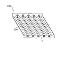
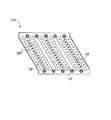
9]図15のヘッドユニット11Mのように、ノズルチップ12M間に壁部がない構成を採用することもできる。図13では、6つのノズルチップ12Mに対して前後方向の外側に、ホルダ14Mの2つの第1壁部21Mがそれぞれ配置されている。各第1壁部21Mの下面には6つの第1凸部31Mが形成されている。この構成においても、第1凸部31Mが固定板に当接した状態で、第1壁部21Mが固定板に接合されることにより、固定板の高精度な平面度を実現できる。
9] As in the
尚、図15の構成は、1つのノズルチップ12Mが、2種類以上のインクを吐出する構成の場合に特に適している。例えば、図13では、各ノズルチップ12Mの複数のノズルのうち、前側のノズル15Maはブラックインクを吐出するノズル、後側のノズル15Mbはイエローインクを吐出するノズルである。この場合に、1色のインクを吐出するノズル列の長さが半分となるため、2つのノズルチップ12Mの距離をかなり小さくしないと、2つのノズルチップ12Mの間で、同色のインクを吐出するノズルを連続させたり、重ねたりすることができない。そのため、図13のような2色以上のインクを吐出するノズルチップ12Mを用いる場合には、2つのノズルチップ12Mの間にホルダ14Mの壁部がなく、2つのノズルチップ12Mが壁部を介さずに左右に並ぶ構成を採用することが好ましい。
The configuration shown in FIG. 15 is particularly suitable for a configuration in which one
上述したように、前記実施形態の構成(図5)と比べると、1色のインクを吐出するノズル列の長さが半分となる。そのため、隣接する2つのノズルチップ12Mの間での重なり幅W1は小さくなり、重なるノズル15Mの数を同等にすることは難しい。それでも、2つのノズルチップ12Mの間の繋ぎ目を目立たなくさせるために、2つのノズルチップ12Mの間で重なる同色ノズル15Mの数は、一定以上(例えば、40個)確保したい。
As described above, the length of the nozzle row that ejects ink of one color is halved compared to the configuration of the above embodiment (FIG. 5). For this reason, the overlapping width W1 between two
これについて、図15において、重なり幅W1(=2.111mm)、各色のノズル列のノズル15の総数(200個)については、前記実施形態の半分とする。一方、チップ長手方向におけるノズル15Mの配列ピッチ(84.7μm)、ノズルチップ12Mの左右方向に対する傾き(60度)は同じとする。この場合、2つのノズルチップ12Mの間で重なる同色のノズル15Mの数は約50個、即ち、1つのヘッドチップ12M内の同色のノズル数のうちの1/4が重なる。
In this regard, in FIG. 15, the overlap width W1 (= 2.111 mm) and the total number (200) of the
尚、図15のノズルチップ12Mにおいて、前側に位置するブラックのノズル15Maが、本発明の「第1ノズル」に相当し、後側に位置するイエローのノズル15Mbが、本発明の「第2ノズル」に相当する。
In the
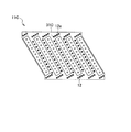
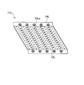
また、図15の変形例として、図16のヘッドユニット11Nのように、1つのノズルチップ12Nが2つのノズル列を有するものであってもよい。2つのノズル列のチップ長手方向一方側部分と他方側部分とで、吐出するインクの種類が異なる点については、図15の形態と同じである。但し、図16では、ブラックインクとイエローインクを吐出する2つのノズルチップ12Naと、シアンインクとマゼンタインクを吐出する2つのノズルチップ12Nbとが、用紙幅方向に交互に並んでいる。つまり、2つのノズルチップ12Naの間に、別のインクを吐出するノズルチップ12Nbが配置されている。この構成では、1つのヘッドユニットから4色のインクを吐出できるため、4色のインクジェットヘッドが搬送方向に並べられた構成と比べて、搬送方向のサイズが小さいカラーインクジェットプリンタとすることができる。
As a modification of FIG. 15, one
10]前記実施形態では、個々のヘッドユニットに対して、ホルダや固定板が設けられている。即ち、複数のヘッドユニットの間で、ホルダや固定板が分離した構成である。これに対して、複数のヘッドユニットの間でホルダや固定板が互いに連結され、一体化された構成であってもよい。 10] In the above embodiment, a holder and a fixing plate are provided for each head unit. That is, the holder and the fixing plate are separated between the plurality of head units. On the other hand, the structure which the holder and the fixed board were mutually connected between several head units and integrated may be sufficient.
11]前記実施形態の図4、図5では、ホルダ14の搬送方向の縁が左右方向に平行になっているが、この縁が、ノズルチップ12の端面形状に応じてジグザグ状になっていてもよい。
11] In FIG. 4 and FIG. 5 of the above-described embodiment, the edge of the
12]前記実施形態の図5では、チップ長手方向に延びる第2壁部22の両端部が第1壁部21と連続的に繋がっているが、第2壁部が第1壁部と繋がっていなくてもよい。例えば、ノズルチップ12の端部付近や中央部など、第2凸部32を配置したい位置にさえ第2壁部22が設けられていればよく、それ以外の位置には第2壁部22がなくてもよい。
12] In FIG. 5 of the above embodiment, both end portions of the
以上説明した実施形態は、本発明を、記録用紙にインクを吐出して画像等を印刷するインクジェットヘッドに適用したものであるが、画像等の印刷以外の様々な用途で使用される液体吐出装置においても本発明は適用されうる。例えば、基板に導電性の液体を吐出して、基板表面に導電パターンを形成する液体吐出装置にも、本発明を適用することは可能である。 In the embodiment described above, the present invention is applied to an ink jet head that prints an image or the like by ejecting ink onto a recording sheet. However, the liquid ejecting apparatus is used for various purposes other than printing an image or the like. The present invention can also be applied. For example, the present invention can also be applied to a liquid ejection apparatus that ejects a conductive liquid onto a substrate to form a conductive pattern on the surface of the substrate.
4 インクジェットヘッド
11 ヘッドユニット
12 ノズルチップ
12a 端面
13 固定板
14 ホルダ
15 ノズル
16 吐出面
21 第1壁部
22 第2壁部
31 第1凸部
32 第2凸部
4
Claims (20)
前記複数のノズルチップを前記吐出面と反対側から保持するホルダと、
前記複数のノズルチップの前記吐出面側に配置され、前記複数のノズルチップが固定される固定板と、を有し、
前記ホルダは、前記複数のノズルチップに対して前記第2方向における外側に配置された第1壁部を有し、前記第1方向において前記ノズルチップが前記ホルダから露出し、
前記第1壁部の前記固定板側の端面に、前記固定板に当接する複数の第1凸部が形成されていることを特徴とするヘッドユニット。 Arranged side by side in the first direction and each arranged in a third direction that is parallel to the ejection surface and intersects the first direction and the second direction orthogonal to the first direction, respectively. A plurality of nozzle tips having nozzles;
A holder for holding the plurality of nozzle tips from the side opposite to the ejection surface;
A fixing plate that is disposed on the discharge surface side of the plurality of nozzle chips and to which the plurality of nozzle chips are fixed;
The holder has a first wall portion arranged on the outer side in the second direction with respect to the plurality of nozzle tips, and the nozzle tip is exposed from the holder in the first direction,
The head unit, wherein a plurality of first convex portions that contact the fixed plate are formed on an end surface of the first wall portion on the fixed plate side.
前記第1壁部の一部が、前記第1方向に隣接する2つの前記ノズルチップの前記端部の間に入り込むように配置されていることを特徴とする請求項1に記載の液体吐出装置。 The end surface of the nozzle tip in the third direction intersects the first direction,
2. The liquid ejection device according to claim 1, wherein a part of the first wall portion is disposed so as to enter between the end portions of two nozzle chips adjacent in the first direction. .
前記第2壁部の前記固定板側の端面に、前記固定板に当接する複数の第2凸部が形成されていることを特徴とする請求項1〜6の何れかに記載のヘッドユニット。 The holder has a second wall portion that is disposed between two nozzle chips adjacent in the first direction and extends in the third direction;
The head unit according to any one of claims 1 to 6, wherein a plurality of second convex portions that are in contact with the fixed plate are formed on an end surface of the second wall portion on the fixed plate side.
前記第2壁部は、前記第1方向における端側の2つの前記ノズルチップ間に、配置されていることを特徴とする請求項7又は8に記載のヘッドユニット。 Having at least four nozzle tips,
The head unit according to claim 7 or 8, wherein the second wall portion is disposed between the two nozzle chips on the end side in the first direction.
一方の前記第2壁部の前記第2凸部と他方の前記第2壁部の前記第2凸部とが、前記吐出面に平行で、且つ、前記第3方向と直交する第4方向において、前記ノズルチップを挟んで向かい合うように配置されていることを特徴とする請求項7〜15の何れかに記載のヘッドユニット。 Two second wall portions are respectively disposed on both sides of the one nozzle tip in the first direction,
In the fourth direction, the second convex portion of one of the second wall portions and the second convex portion of the other second wall portion are parallel to the ejection surface and orthogonal to the third direction. The head unit according to claim 7, wherein the head unit is disposed so as to face each other with the nozzle chip interposed therebetween.
前記第1方向に隣接する2つの前記ノズルチップの間には、前記ホルダの壁部が配置されていないことを特徴とする請求項1〜6の何れかに記載のヘッドユニット。 Among the plurality of nozzles of one nozzle chip, the first nozzle arranged on one side in the third direction and the second nozzle arranged on the other side in the third direction are different types of liquids. Discharge
The head unit according to claim 1, wherein a wall portion of the holder is not disposed between the two nozzle chips adjacent to each other in the first direction.
各ヘッドユニットは、
吐出面に平行で、且つ、前記第1方向及び前記第1方向と直交する第2方向とそれぞれ交差する、第3方向に配列されたノズルを有し、前記第1方向に並んで配置された複数のノズルチップと、
前記複数のノズルチップを前記吐出面と反対側から保持するホルダと、
前記複数のノズルチップの前記吐出面側に配置され、前記複数のノズルチップが固定される固定板と、を有し、
前記ホルダは、前記複数のノズルチップに対して前記第2方向における外側に配置された第1壁部を有し、前記第1方向において前記ノズルチップが前記ホルダから露出し、
前記第1壁部の前記固定板側の端面に、前記固定板に当接する複数の第1凸部が形成されていることを特徴とする液体吐出装置。 A plurality of head units arranged in the first direction;
Each head unit
The nozzles are arranged in a third direction parallel to the discharge surface and intersecting the first direction and the second direction orthogonal to the first direction, respectively, and are arranged side by side in the first direction. A plurality of nozzle tips;
A holder for holding the plurality of nozzle tips from the side opposite to the ejection surface;
A fixing plate that is disposed on the discharge surface side of the plurality of nozzle chips and to which the plurality of nozzle chips are fixed;
The holder has a first wall portion arranged on the outer side in the second direction with respect to the plurality of nozzle tips, and the nozzle tip is exposed from the holder in the first direction,
The liquid ejection apparatus according to claim 1, wherein a plurality of first convex portions that contact the fixed plate are formed on an end surface of the first wall portion on the fixed plate side.
Priority Applications (3)
| Application Number | Priority Date | Filing Date | Title |
|---|---|---|---|
| JP2016070943A JP6790419B2 (en) | 2016-03-31 | 2016-03-31 | Head unit and liquid discharge device |
| CN201710164766.7A CN107379769B (en) | 2016-03-31 | 2017-03-20 | Head unit and liquid injection apparatus |
| US15/464,882 US10189273B2 (en) | 2016-03-31 | 2017-03-21 | Head unit having nozzle chips arranged side by side and liquid jetting apparatus including the same |
Applications Claiming Priority (1)
| Application Number | Priority Date | Filing Date | Title |
|---|---|---|---|
| JP2016070943A JP6790419B2 (en) | 2016-03-31 | 2016-03-31 | Head unit and liquid discharge device |
Publications (2)
| Publication Number | Publication Date |
|---|---|
| JP2017177662A true JP2017177662A (en) | 2017-10-05 |
| JP6790419B2 JP6790419B2 (en) | 2020-11-25 |
Family
ID=59959087
Family Applications (1)
| Application Number | Title | Priority Date | Filing Date |
|---|---|---|---|
| JP2016070943A Active JP6790419B2 (en) | 2016-03-31 | 2016-03-31 | Head unit and liquid discharge device |
Country Status (3)
| Country | Link |
|---|---|
| US (1) | US10189273B2 (en) |
| JP (1) | JP6790419B2 (en) |
| CN (1) | CN107379769B (en) |
Cited By (1)
| Publication number | Priority date | Publication date | Assignee | Title |
|---|---|---|---|---|
| JP7467125B2 (en) | 2020-01-07 | 2024-04-15 | キヤノン株式会社 | LIQUID EJECTION HEAD AND LIQUID EJECTION APPARATUS |
Families Citing this family (12)
| Publication number | Priority date | Publication date | Assignee | Title |
|---|---|---|---|---|
| EP3703953A4 (en) * | 2018-03-12 | 2021-06-16 | Hewlett-Packard Development Company, L.P. | Nozzle arrangements |
| US11305537B2 (en) | 2018-03-12 | 2022-04-19 | Hewlett-Packard Development Company, L.P. | Nozzle arrangements and supply channels |
| EP3707003B1 (en) | 2018-03-12 | 2023-07-19 | Hewlett-Packard Development Company, L.P. | Nozzle arrangements and feed holes |
| JP7154897B2 (en) * | 2018-09-06 | 2022-10-18 | キヤノン株式会社 | LIQUID EJECTION HEAD AND METHOD FOR MANUFACTURING LIQUID EJECTION HEAD |
| JP7347012B2 (en) * | 2019-08-29 | 2023-09-20 | セイコーエプソン株式会社 | Liquid ejection device and support |
| JP7001115B2 (en) * | 2020-02-27 | 2022-01-19 | セイコーエプソン株式会社 | Liquid injection head, head unit, and liquid injection device |
| CN113752692A (en) | 2020-06-01 | 2021-12-07 | 精工爱普生株式会社 | Liquid ejecting head and liquid ejecting apparatus |
| JP2022023542A (en) | 2020-07-27 | 2022-02-08 | セイコーエプソン株式会社 | Liquid jet head, and liquid jet device |
| JP2021194881A (en) | 2020-06-17 | 2021-12-27 | セイコーエプソン株式会社 | Liquid jet head and liquid jet device |
| JP2021187075A (en) | 2020-06-01 | 2021-12-13 | セイコーエプソン株式会社 | Liquid jet head and liquid jet device |
| CN113752691A (en) * | 2020-06-01 | 2021-12-07 | 精工爱普生株式会社 | Liquid ejecting head and liquid ejecting apparatus |
| JP2022040498A (en) | 2020-08-31 | 2022-03-11 | セイコーエプソン株式会社 | Liquid discharge device, head driving circuit and liquid discharge head |
Citations (5)
| Publication number | Priority date | Publication date | Assignee | Title |
|---|---|---|---|---|
| US6076912A (en) * | 1998-06-03 | 2000-06-20 | Lexmark International, Inc. | Thermally conductive, corrosion resistant printhead structure |
| JP2007237439A (en) * | 2006-03-06 | 2007-09-20 | Fuji Xerox Co Ltd | Liquid droplet delivering head, liquid droplet delivering apparatus, manufacturing method for the same |
| CN102675970A (en) * | 2011-03-16 | 2012-09-19 | 富士胶片株式会社 | Ink composition, ink group and method for forming image |
| JP2015110305A (en) * | 2013-12-06 | 2015-06-18 | セイコーエプソン株式会社 | Liquid jet head, liquid jet head unit, and liquid jet device |
| JP2015120292A (en) * | 2013-12-24 | 2015-07-02 | セイコーエプソン株式会社 | Liquid jet head, liquid jet device, and manufacturing method of liquid jet head |
Family Cites Families (5)
| Publication number | Priority date | Publication date | Assignee | Title |
|---|---|---|---|---|
| JP3908401B2 (en) * | 1998-12-22 | 2007-04-25 | ローム株式会社 | Drive IC chip for print head and print head having the same |
| JP4298334B2 (en) * | 2003-03-17 | 2009-07-15 | キヤノン株式会社 | Recording method and recording apparatus |
| JP4431114B2 (en) * | 2004-01-07 | 2010-03-10 | ヒューレット・パッカード インダストリアル プリンティング リミテッド | Inkjet recording head |
| JP2010264700A (en) * | 2009-05-15 | 2010-11-25 | Seiko Epson Corp | Method for manufacturing liquid ejection head unit and liquid ejection device |
| JP6350792B2 (en) * | 2013-12-09 | 2018-07-04 | セイコーエプソン株式会社 | Liquid ejecting apparatus and liquid ejecting head unit |
-
2016
- 2016-03-31 JP JP2016070943A patent/JP6790419B2/en active Active
-
2017
- 2017-03-20 CN CN201710164766.7A patent/CN107379769B/en active Active
- 2017-03-21 US US15/464,882 patent/US10189273B2/en active Active
Patent Citations (5)
| Publication number | Priority date | Publication date | Assignee | Title |
|---|---|---|---|---|
| US6076912A (en) * | 1998-06-03 | 2000-06-20 | Lexmark International, Inc. | Thermally conductive, corrosion resistant printhead structure |
| JP2007237439A (en) * | 2006-03-06 | 2007-09-20 | Fuji Xerox Co Ltd | Liquid droplet delivering head, liquid droplet delivering apparatus, manufacturing method for the same |
| CN102675970A (en) * | 2011-03-16 | 2012-09-19 | 富士胶片株式会社 | Ink composition, ink group and method for forming image |
| JP2015110305A (en) * | 2013-12-06 | 2015-06-18 | セイコーエプソン株式会社 | Liquid jet head, liquid jet head unit, and liquid jet device |
| JP2015120292A (en) * | 2013-12-24 | 2015-07-02 | セイコーエプソン株式会社 | Liquid jet head, liquid jet device, and manufacturing method of liquid jet head |
Cited By (1)
| Publication number | Priority date | Publication date | Assignee | Title |
|---|---|---|---|---|
| JP7467125B2 (en) | 2020-01-07 | 2024-04-15 | キヤノン株式会社 | LIQUID EJECTION HEAD AND LIQUID EJECTION APPARATUS |
Also Published As
| Publication number | Publication date |
|---|---|
| JP6790419B2 (en) | 2020-11-25 |
| CN107379769A (en) | 2017-11-24 |
| US10189273B2 (en) | 2019-01-29 |
| US20170282553A1 (en) | 2017-10-05 |
| CN107379769B (en) | 2019-10-15 |
Similar Documents
| Publication | Publication Date | Title |
|---|---|---|
| JP6790419B2 (en) | Head unit and liquid discharge device | |
| EP1186416B1 (en) | Carrier positioning for wide-array inkjet printhead assembly | |
| JP6686637B2 (en) | Liquid ejector | |
| KR100618500B1 (en) | Liquid ejecting recording head and liquid ejecting recording apparatus | |
| US6793319B2 (en) | Printer and printer head | |
| JP7196740B2 (en) | liquid ejection head | |
| KR20050042244A (en) | Ink jet print head, ink jet printer with ink jet print head, and method of manufacturing ink jet print head | |
| US6174046B1 (en) | Reliable contact pad arrangement on plastic print cartridge | |
| JP6390495B2 (en) | Liquid ejection device and liquid ejection head | |
| US9254656B2 (en) | Liquid ejecting head, liquid ejecting apparatus, and manufacturing method of liquid ejecting head | |
| US6773089B2 (en) | Liquid discharge head, and head cartridge and image forming apparatus using such liquid discharge head | |
| JP5206164B2 (en) | Head unit and liquid ejection apparatus provided with the same | |
| JP6413805B2 (en) | Liquid ejection device | |
| US9199461B2 (en) | Print head die | |
| US20120188308A1 (en) | Inkjet printheads and fluid ejecting chips | |
| US9358788B2 (en) | Print head die | |
| JP5188049B2 (en) | Recording head | |
| JP2005059337A (en) | Ink jet head and ink jet printer | |
| US8172374B2 (en) | Liquid ejecting head, liquid ejecting apparatus, and method for manufacturing liquid ejecting head | |
| US10960671B2 (en) | Liquid ejecting head including first plate, second plate, and protrusion protruding from second plate | |
| JP6975413B2 (en) | Liquid discharge device | |
| CN109849517B (en) | Head chip, liquid ejecting head, and liquid ejecting recording apparatus | |
| JP6760339B2 (en) | Liquid discharge device and liquid discharge head | |
| JPH0929982A (en) | Ink jet recording device | |
| JP2022010082A (en) | Liquid discharge device |
Legal Events
| Date | Code | Title | Description |
|---|---|---|---|
| A621 | Written request for application examination |
Free format text: JAPANESE INTERMEDIATE CODE: A621 Effective date: 20190314 |
|
| A977 | Report on retrieval |
Free format text: JAPANESE INTERMEDIATE CODE: A971007 Effective date: 20200116 |
|
| A131 | Notification of reasons for refusal |
Free format text: JAPANESE INTERMEDIATE CODE: A131 Effective date: 20200303 |
|
| A521 | Request for written amendment filed |
Free format text: JAPANESE INTERMEDIATE CODE: A523 Effective date: 20200409 |
|
| TRDD | Decision of grant or rejection written | ||
| A01 | Written decision to grant a patent or to grant a registration (utility model) |
Free format text: JAPANESE INTERMEDIATE CODE: A01 Effective date: 20201006 |
|
| A61 | First payment of annual fees (during grant procedure) |
Free format text: JAPANESE INTERMEDIATE CODE: A61 Effective date: 20201019 |
|
| R150 | Certificate of patent or registration of utility model |
Ref document number: 6790419 Country of ref document: JP Free format text: JAPANESE INTERMEDIATE CODE: R150 |