JP2017173619A - Developing cartridge - Google Patents

Developing cartridge Download PDF

Info

Publication number
JP2017173619A
JP2017173619A JP2016060606A JP2016060606A JP2017173619A JP 2017173619 A JP2017173619 A JP 2017173619A JP 2016060606 A JP2016060606 A JP 2016060606A JP 2016060606 A JP2016060606 A JP 2016060606A JP 2017173619 A JP2017173619 A JP 2017173619A
Authority
JP
Japan
Prior art keywords
gear
developing cartridge
protrusion
predetermined direction
teeth
Prior art date
Legal status (The legal status is an assumption and is not a legal conclusion. Google has not performed a legal analysis and makes no representation as to the accuracy of the status listed.)
Pending
Application number
JP2016060606A
Other languages
Japanese (ja)
Inventor
板橋 奈緒
Nao Itabashi
奈緒 板橋
Current Assignee (The listed assignees may be inaccurate. Google has not performed a legal analysis and makes no representation or warranty as to the accuracy of the list.)
Brother Industries Ltd
Original Assignee
Brother Industries Ltd
Priority date (The priority date is an assumption and is not a legal conclusion. Google has not performed a legal analysis and makes no representation as to the accuracy of the date listed.)
Filing date
Publication date
Application filed by Brother Industries Ltd filed Critical Brother Industries Ltd
Priority to JP2016060606A priority Critical patent/JP2017173619A/en
Priority to US15/275,698 priority patent/US9964917B2/en
Priority to PCT/JP2016/078175 priority patent/WO2017163465A1/en
Priority to CN201680083886.8A priority patent/CN109074015B/en
Publication of JP2017173619A publication Critical patent/JP2017173619A/en
Pending legal-status Critical Current

Links

Images

Classifications

    • GPHYSICS
    • G03PHOTOGRAPHY; CINEMATOGRAPHY; ANALOGOUS TECHNIQUES USING WAVES OTHER THAN OPTICAL WAVES; ELECTROGRAPHY; HOLOGRAPHY
    • G03GELECTROGRAPHY; ELECTROPHOTOGRAPHY; MAGNETOGRAPHY
    • G03G21/00Arrangements not provided for by groups G03G13/00 - G03G19/00, e.g. cleaning, elimination of residual charge
    • G03G21/16Mechanical means for facilitating the maintenance of the apparatus, e.g. modular arrangements
    • G03G21/1642Mechanical means for facilitating the maintenance of the apparatus, e.g. modular arrangements for connecting the different parts of the apparatus
    • G03G21/1647Mechanical connection means
    • FMECHANICAL ENGINEERING; LIGHTING; HEATING; WEAPONS; BLASTING
    • F16ENGINEERING ELEMENTS AND UNITS; GENERAL MEASURES FOR PRODUCING AND MAINTAINING EFFECTIVE FUNCTIONING OF MACHINES OR INSTALLATIONS; THERMAL INSULATION IN GENERAL
    • F16HGEARING
    • F16H1/00Toothed gearings for conveying rotary motion
    • F16H1/02Toothed gearings for conveying rotary motion without gears having orbital motion
    • F16H1/20Toothed gearings for conveying rotary motion without gears having orbital motion involving more than two intermeshing members
    • FMECHANICAL ENGINEERING; LIGHTING; HEATING; WEAPONS; BLASTING
    • F16ENGINEERING ELEMENTS AND UNITS; GENERAL MEASURES FOR PRODUCING AND MAINTAINING EFFECTIVE FUNCTIONING OF MACHINES OR INSTALLATIONS; THERMAL INSULATION IN GENERAL
    • F16HGEARING
    • F16H25/00Gearings comprising primarily only cams, cam-followers and screw-and-nut mechanisms
    • F16H25/16Gearings comprising primarily only cams, cam-followers and screw-and-nut mechanisms for interconverting rotary motion and oscillating motion
    • GPHYSICS
    • G03PHOTOGRAPHY; CINEMATOGRAPHY; ANALOGOUS TECHNIQUES USING WAVES OTHER THAN OPTICAL WAVES; ELECTROGRAPHY; HOLOGRAPHY
    • G03GELECTROGRAPHY; ELECTROPHOTOGRAPHY; MAGNETOGRAPHY
    • G03G15/00Apparatus for electrographic processes using a charge pattern
    • G03G15/06Apparatus for electrographic processes using a charge pattern for developing
    • G03G15/08Apparatus for electrographic processes using a charge pattern for developing using a solid developer, e.g. powder developer
    • G03G15/0822Arrangements for preparing, mixing, supplying or dispensing developer
    • G03G15/0865Arrangements for supplying new developer
    • GPHYSICS
    • G03PHOTOGRAPHY; CINEMATOGRAPHY; ANALOGOUS TECHNIQUES USING WAVES OTHER THAN OPTICAL WAVES; ELECTROGRAPHY; HOLOGRAPHY
    • G03GELECTROGRAPHY; ELECTROPHOTOGRAPHY; MAGNETOGRAPHY
    • G03G15/00Apparatus for electrographic processes using a charge pattern
    • G03G15/06Apparatus for electrographic processes using a charge pattern for developing
    • G03G15/08Apparatus for electrographic processes using a charge pattern for developing using a solid developer, e.g. powder developer
    • G03G15/0822Arrangements for preparing, mixing, supplying or dispensing developer
    • G03G15/0887Arrangements for conveying and conditioning developer in the developing unit, e.g. agitating, removing impurities or humidity
    • GPHYSICS
    • G03PHOTOGRAPHY; CINEMATOGRAPHY; ANALOGOUS TECHNIQUES USING WAVES OTHER THAN OPTICAL WAVES; ELECTROGRAPHY; HOLOGRAPHY
    • G03GELECTROGRAPHY; ELECTROPHOTOGRAPHY; MAGNETOGRAPHY
    • G03G21/00Arrangements not provided for by groups G03G13/00 - G03G19/00, e.g. cleaning, elimination of residual charge
    • G03G21/16Mechanical means for facilitating the maintenance of the apparatus, e.g. modular arrangements
    • G03G21/1661Mechanical means for facilitating the maintenance of the apparatus, e.g. modular arrangements means for handling parts of the apparatus in the apparatus
    • G03G21/1676Mechanical means for facilitating the maintenance of the apparatus, e.g. modular arrangements means for handling parts of the apparatus in the apparatus for the developer unit
    • GPHYSICS
    • G03PHOTOGRAPHY; CINEMATOGRAPHY; ANALOGOUS TECHNIQUES USING WAVES OTHER THAN OPTICAL WAVES; ELECTROGRAPHY; HOLOGRAPHY
    • G03GELECTROGRAPHY; ELECTROPHOTOGRAPHY; MAGNETOGRAPHY
    • G03G21/00Arrangements not provided for by groups G03G13/00 - G03G19/00, e.g. cleaning, elimination of residual charge
    • G03G21/16Mechanical means for facilitating the maintenance of the apparatus, e.g. modular arrangements
    • G03G21/18Mechanical means for facilitating the maintenance of the apparatus, e.g. modular arrangements using a processing cartridge, whereby the process cartridge comprises at least two image processing means in a single unit
    • G03G21/1875Mechanical means for facilitating the maintenance of the apparatus, e.g. modular arrangements using a processing cartridge, whereby the process cartridge comprises at least two image processing means in a single unit provided with identifying means or means for storing process- or use parameters, e.g. lifetime of the cartridge
    • G03G21/1896Mechanical means for facilitating the maintenance of the apparatus, e.g. modular arrangements using a processing cartridge, whereby the process cartridge comprises at least two image processing means in a single unit provided with identifying means or means for storing process- or use parameters, e.g. lifetime of the cartridge mechanical or optical identification means, e.g. protrusions, bar codes

Abstract

PROBLEM TO BE SOLVED: To provide a developing cartridge capable of easily increasing the number of signal patterns formed by rotation of a protrusion.SOLUTION: A developing cartridge comprises: a first gear 14 which can rotate when receiving driving force and which is movable from a first position to a second position; a second gear 15 which can rotate when receiving the driving force from the first gear 14; a gear cover which has an opening and covers at least parts of the first gear 14 and the second gear 15; and a protrusion 16 which can rotate with the second gear 15. The protrusion 16 rotates with the second gear 15 during a period in which the first gear 14 moves from the first position to the second position, and after passing through the opening once during rotation with the second gear 15, passes through the opening at least once.SELECTED DRAWING: Figure 4

Description

本開示は、現像カートリッジに関する。   The present disclosure relates to a developing cartridge.

従来、現像ローラを備える現像カートリッジが知られている。現像カートリッジは、画像形成装置に対して着脱可能である。   Conventionally, a developing cartridge including a developing roller is known. The developing cartridge is detachable from the image forming apparatus.

例えば、現像カートリッジは、第1位置から第2位置まで回転可能なギアと、ギアに設けられる突起とを備える。突起は、ギアと共に回転し、画像形成装置のレバーと接触する。レバーは、突起との接触により移動する。画像形成装置は、レバーの移動を検知して現像カートリッジの仕様を判断する(特許文献1参照。)。   For example, the developing cartridge includes a gear that can rotate from a first position to a second position, and a protrusion provided on the gear. The protrusion rotates with the gear and contacts the lever of the image forming apparatus. The lever moves by contact with the protrusion. The image forming apparatus detects the movement of the lever and determines the specification of the developing cartridge (see Patent Document 1).

特開2013−54058号公報JP2013-54058A

上記した現像カートリッジの小型化が要望される一方で、現像カートリッジの仕様数は、増加する傾向にある。   While it is desired to reduce the size of the developing cartridge described above, the number of specifications of the developing cartridge tends to increase.

仕様数の増加に対応するために、仕様の異なる現像カートリッジ毎に、突起が回転することにより形成される信号パターンを異ならせることが検討される。   In order to cope with the increase in the number of specifications, it is considered to vary the signal pattern formed by the rotation of the protrusion for each developing cartridge having different specifications.

そこで、本開示の目的は、突起が回転することにより形成される信号パターンを、容易に増加させることができる現像カートリッジを提供することにある。   Accordingly, an object of the present disclosure is to provide a developing cartridge that can easily increase a signal pattern formed by rotation of a protrusion.

(1)本開示の現像カートリッジは、第1ギアと、第2ギアと、ギアカバーと、突起とを備える。第1ギアは、所定の方向に延びる第1軸について回転可能である。第1ギアは、第1位置から第2位置まで移動可能である。第2ギアは、第1ギアから駆動力を受けて、所定の方向に延びる第2軸について回転可能である。ギアカバーは、開口を有する。ギアカバーは、第2ギアの少なくとも一部を覆う。 (1) The developing cartridge according to the present disclosure includes a first gear, a second gear, a gear cover, and a protrusion. The first gear is rotatable about a first shaft extending in a predetermined direction. The first gear is movable from the first position to the second position. The second gear receives a driving force from the first gear and can rotate about a second shaft extending in a predetermined direction. The gear cover has an opening. The gear cover covers at least a part of the second gear.

突起は、所定の方向に延びる。突起は、第2ギアとともに回転可能である。突起は、第1ギアが第1位置から第2位置まで移動する間、第2ギアとともに回転可能である。突起は、第2ギアとともに回転している間に、開口を1回通過した後、さらに、少なくとも1回、開口を通過する。   The protrusion extends in a predetermined direction. The protrusion is rotatable with the second gear. The protrusion is rotatable with the second gear while the first gear moves from the first position to the second position. The protrusion passes through the opening at least once after passing through the opening once while rotating with the second gear.

このような構成によれば、突起は、第1ギアが第1位置から第2位置まで移動する間、第2ギアとともに回転し、開口を1回通過した後、さらに、少なくとも1回、開口を通過する。   According to such a configuration, the protrusion rotates with the second gear while the first gear moves from the first position to the second position, passes through the opening once, and then opens the opening at least once. pass.

これにより、突起が開口を通過する回数を変更して、突起が回転することにより形成される信号パターンを、容易に増加させることができる。なお、突起が開口を通過する回数は、例えば、第1ギアと第2ギアとのギア比を調整するなどにより、容易に変更できる。
(2)現像カートリッジは、第1ギアと噛み合うアイドルギアを、さらに備えてもよい。第1ギアとアイドルギアとの噛み合いが解除されることにより、第2ギアが停止する。
(3)第1ギアは、第2ギアと噛み合ってもよい。第1ギアと第2ギアとの噛み合いが解除されることにより、第2ギアが停止する。
(4)第1ギアは、第1ギアの周囲の一部に、複数のギア歯を有してもよい。
(5)第1ギアは、欠け歯部分を有してもよい。
(6)現像カートリッジは、第1ギアと噛み合うアイドルギアを、さらに備えてもよい。第1ギアが第2位置のときに、第1ギアは、アイドルギアの複数のギア歯のいずれのギア歯とも噛み合わなくてもよい。
(7)第2ギアは、第2ギアの周囲に複数のギア歯を有してもよい。第1ギアが有する複数のギア歯の歯数は、第2ギアが有する複数のギア歯の歯数の1.5倍以上であってもよい。
(8)第1ギアの歯先円の径は、第2ギアの歯先円の径の1.5倍以上であってもよい。
(9)第1ギアは、所定の方向において、第1位置から第2位置まで移動可能であってもよい。
(10)現像カートリッジは、第1ギアを第2位置に固定するストッパを、さらに備えてもよい。
(11)現像カートリッジは、現像剤を収容可能なカートリッジであってもよい。
(12)現像カートリッジは、所定の方向に延びる第3軸についてピボット可能なピボット部材を、さらに備えてもよい。ピボット部材は、突起が接触することによりピボットする。第1ギアが第1位置から第2位置まで移動する間、突起は、ピボット部材に、1回接触した後、さらに、少なくとも1回、接触する。
Thereby, the signal pattern formed by changing the number of times the protrusion passes through the opening and rotating the protrusion can be easily increased. Note that the number of times the protrusion passes through the opening can be easily changed, for example, by adjusting the gear ratio between the first gear and the second gear.
(2) The developing cartridge may further include an idle gear that meshes with the first gear. When the meshing between the first gear and the idle gear is released, the second gear stops.
(3) The first gear may mesh with the second gear. When the meshing between the first gear and the second gear is released, the second gear stops.
(4) The first gear may have a plurality of gear teeth in a part of the periphery of the first gear.
(5) The first gear may have a missing tooth portion.
(6) The developing cartridge may further include an idle gear that meshes with the first gear. When the first gear is in the second position, the first gear may not mesh with any of the plurality of gear teeth of the idle gear.
(7) The second gear may have a plurality of gear teeth around the second gear. The number of teeth of the plurality of gear teeth included in the first gear may be 1.5 times or more the number of teeth of the plurality of gear teeth included in the second gear.
(8) The diameter of the tip circle of the first gear may be 1.5 times or more the diameter of the tip circle of the second gear.
(9) The first gear may be movable from the first position to the second position in a predetermined direction.
(10) The developing cartridge may further include a stopper for fixing the first gear to the second position.
(11) The developing cartridge may be a cartridge that can store a developer.
(12) The developing cartridge may further include a pivot member pivotable about a third axis extending in a predetermined direction. The pivot member pivots when the protrusion comes into contact. While the first gear moves from the first position to the second position, the protrusion contacts the pivot member once and then contacts at least once more.

本発明の現像カートリッジは、突起が回転することにより形成される信号パターンを、容易に増加させることができる。   The developing cartridge of the present invention can easily increase the signal pattern formed by the rotation of the protrusion.

図1は、現像カートリッジの概略構成図である。FIG. 1 is a schematic configuration diagram of a developing cartridge. 図2は、現像カートリッジに設けられるギア列の概略を説明するための説明図である。FIG. 2 is an explanatory diagram for explaining an outline of a gear train provided in the developing cartridge. 図3は、第1実施形態の現像カートリッジを示す斜視図である。FIG. 3 is a perspective view showing the developing cartridge of the first embodiment. 図4は、第1実施形態の現像カートリッジに設けられるギア列を示す斜視図である。FIG. 4 is a perspective view showing a gear train provided in the developing cartridge of the first embodiment. 図5は、図4に示すギア列を分解した斜視図である。FIG. 5 is an exploded perspective view of the gear train shown in FIG. 図6は、図4に示すアジテータギア、アイドルギア、第1ギアおよび第2ギアの噛み合いを説明するための説明図である。FIG. 6 is an explanatory diagram for explaining meshing of the agitator gear, the idle gear, the first gear, and the second gear shown in FIG. 図7Aは、第1実施形態の現像カートリッジの動作を説明する説明図であって、第1ギアが第1位置に位置した状態を示す。図7Bは、図7Aに続いて、第1実施形態の現像カートリッジの動作を説明する説明図であって、突起がアクチュエータを離間位置に移動させた状態を示す。FIG. 7A is an explanatory diagram for explaining the operation of the developing cartridge according to the first embodiment, and shows a state in which the first gear is located at the first position. FIG. 7B is an explanatory diagram for explaining the operation of the developing cartridge according to the first embodiment following FIG. 7A, and shows a state in which the protrusion moves the actuator to the separation position. 図8Aは、図7Bに続いて、第1実施形態の現像カートリッジの動作を説明する説明図であって、突起がアクチュエータから離れ、アクチュエータが接触位置に位置した状態を示す。図8Bは、図8Aに続いて、第1実施形態の現像カートリッジの動作を説明する説明図であって、突起がアクチュエータを、再度、離間位置に移動させた状態を示す。FIG. 8A is an explanatory diagram for explaining the operation of the developing cartridge according to the first embodiment following FIG. 7B, and shows a state in which the protrusion is separated from the actuator and the actuator is located at the contact position. FIG. 8B is an explanatory diagram for explaining the operation of the developing cartridge according to the first embodiment, following FIG. 8A, and shows a state in which the protrusion moves the actuator to the separation position again. 図9は、図8Bに続いて、第1実施形態の現像カートリッジの動作を説明する説明図であって、第1ギアが第2位置に位置した状態を示す。FIG. 9 is an explanatory diagram for explaining the operation of the developing cartridge according to the first embodiment following FIG. 8B, and shows a state where the first gear is located at the second position. 図10は、アクチュエータの移動を示すタイミングチャートである。FIG. 10 is a timing chart showing the movement of the actuator. 図11A、図11B、図11Cおよび図11Dは、それぞれ、突起の変形例を示す斜視図である。FIG. 11A, FIG. 11B, FIG. 11C, and FIG. 11D are perspective views showing modifications of the protrusions, respectively. 図12Aは、図11Aの突起が回転した場合において、アクチュエータの移動を示すタイミングチャートである。図12Bは、図11Bの突起が回転した場合において、アクチュエータの移動を示すタイミングチャートである。図12Cは、図11Cの突起が回転した場合において、アクチュエータの移動を示すタイミングチャートである。図12Dは、図11Dの突起が回転した場合において、アクチュエータの移動を示すタイミングチャートである。FIG. 12A is a timing chart showing the movement of the actuator when the protrusion of FIG. 11A rotates. FIG. 12B is a timing chart showing the movement of the actuator when the protrusion of FIG. 11B rotates. FIG. 12C is a timing chart showing the movement of the actuator when the protrusion of FIG. 11C rotates. FIG. 12D is a timing chart showing the movement of the actuator when the protrusion of FIG. 11D rotates. 図13は、第2実施形態の現像カートリッジに設けられるギア列を示す側面図である。FIG. 13 is a side view showing a gear train provided in the developing cartridge of the second embodiment. 図14は、図13に示すギア列を分解した斜視図である。14 is an exploded perspective view of the gear train shown in FIG. 図15は、第3実施形態の現像カートリッジに設けられるギア列を分解した斜視図である。FIG. 15 is an exploded perspective view of a gear train provided in the developing cartridge of the third embodiment. 図16は、第3実施形態において、第1ギアの移動を説明するための説明図であって、第1ギアが第1位置に位置した状態を示す。FIG. 16 is an explanatory diagram for explaining the movement of the first gear in the third embodiment, and shows a state where the first gear is located at the first position. 図17は、図16とともに第1ギアの移動を説明するための説明図であって、第1ギアが第2位置に位置した状態を示す。FIG. 17 is an explanatory diagram for explaining the movement of the first gear together with FIG. 16, and shows a state where the first gear is located at the second position. 図18は、第3実施形態の変形例を説明する説明図であって、第1ギアが第1位置に位置した状態を示す。FIG. 18 is an explanatory diagram for explaining a modification of the third embodiment, and shows a state in which the first gear is located at the first position. 図19は、図18とともに第3実施形態の変形例を説明する説明図であって、第1ギアが第2位置に位置した状態を示す。FIG. 19 is an explanatory diagram for explaining a modified example of the third embodiment together with FIG. 18, and shows a state in which the first gear is located at the second position. 図20は、第4実施形態の現像カートリッジに設けられるギア列を分解した斜視図である。FIG. 20 is an exploded perspective view of a gear train provided in the developing cartridge according to the fourth embodiment. 図21は、第4実施形態において、第1ギアの移動を説明する説明図であって、第1ギアが第1位置に位置した状態を示す。FIG. 21 is an explanatory diagram for explaining the movement of the first gear in the fourth embodiment, and shows a state in which the first gear is located at the first position. 図22は、図21に続いて、第1ギアの移動を説明する説明図であって、第1ギアが第1位置から回転した状態を示す。FIG. 22 is an explanatory diagram for explaining the movement of the first gear following FIG. 21 and shows a state in which the first gear is rotated from the first position. 図23は、図22に続いて、第1ギアの移動を説明する説明図であって、第1ギアが第2位置に位置した状態を示す。FIG. 23 is an explanatory diagram for explaining the movement of the first gear following FIG. 22 and shows a state in which the first gear is located at the second position. 図24は、第5実施形態の現像カートリッジを説明する説明図である。FIG. 24 is an explanatory diagram illustrating the developing cartridge according to the fifth embodiment.

1.現像カートリッジ1の概略
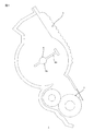
図1を参照して、現像カートリッジ1の概略について説明する。
1. Outline of Developing Cartridge 1 With reference to FIG. 1, the outline of the developing cartridge 1 will be described.

現像カートリッジ1は、現像剤を収容可能なカートリッジである。現像カートリッジ1は、筐体2と、現像ローラ3と、アジテータ4とを備える。現像ローラ3は、所定の方向に延びる回転軸について、回転可能である。   The developing cartridge 1 is a cartridge that can store a developer. The developing cartridge 1 includes a housing 2, a developing roller 3, and an agitator 4. The developing roller 3 is rotatable about a rotation shaft extending in a predetermined direction.

1.1 筐体2
筐体2は、所定の方向に延びる。筐体2は、現像剤を収容可能である。現像剤は、例えば、トナーである。なお、以下の説明において、筐体2の内側および外側に言及するときは、現像剤が収容される側が、筐体2の内側である。また、現像剤が収容される内側と反対側が、筐体2の外側である。
1.1 Housing 2
The housing 2 extends in a predetermined direction. The housing 2 can accommodate a developer. The developer is, for example, toner. In the following description, when the inside and outside of the housing 2 are referred to, the side in which the developer is accommodated is the inside of the housing 2. The side opposite to the inside where the developer is accommodated is the outside of the housing 2.

1.2 現像ローラ3
現像ローラ3は、筐体2の一端部に位置する。現像ローラ3は、所定の方向に延びる。現像ローラ3の周面の一部は、筐体2の外側に露出している。
1.2 Developing roller 3
The developing roller 3 is located at one end of the housing 2. The developing roller 3 extends in a predetermined direction. A part of the peripheral surface of the developing roller 3 is exposed to the outside of the housing 2.

1.3 アジテータ4
アジテータ4は、筐体2内の現像剤を撹拌するとともに、筐体2内の現像剤を現像ローラ3へ送るための構成である。アジテータ4は、筐体2の内部に位置する。アジテータ4は、所定の方向に延びる回転軸について回転可能である。アジテータ4は、アジテータシャフト4Aと、羽根4Bとを備える。アジテータシャフト4Aは、所定の方向に延びる。羽根4Bは、アジテータシャフト4Aから、所定の方向と交差する方向に延びる。
1.3 Agitator 4
The agitator 4 is configured to agitate the developer in the housing 2 and to send the developer in the housing 2 to the developing roller 3. The agitator 4 is located inside the housing 2. The agitator 4 is rotatable about a rotation shaft extending in a predetermined direction. The agitator 4 includes an agitator shaft 4A and a blade 4B. The agitator shaft 4A extends in a predetermined direction. The blade 4B extends from the agitator shaft 4A in a direction intersecting with a predetermined direction.

2.現像カートリッジ1に設けられるギア列の概略
図2を参照して、現像カートリッジ1に設けられるギア列の概略について説明する。
2. Outline of Gear Train Provided in Developing Cartridge 1 With reference to FIG. 2, an outline of a gear train provided in the developing cartridge 1 will be described.

現像カートリッジ1は、画像形成装置からの駆動力を受けて駆動するギア列を備える。具体的には、現像カートリッジ1は、アジテータギア5と、第1ギア6と、アイドルギア7と、第2ギア8と、突起9とを備える。   The developing cartridge 1 includes a gear train that is driven by receiving a driving force from the image forming apparatus. Specifically, the developing cartridge 1 includes an agitator gear 5, a first gear 6, an idle gear 7, a second gear 8, and a protrusion 9.

アジテータギア5は、画像形成装置から現像カートリッジ1に入力された駆動力を受けて回転可能である。アジテータギア5は、アジテータシャフト4Aとともに回転可能である。アジテータギア5は、アジテータギア5の周囲に、複数のギア歯を有する。複数のギア歯は、アジテータギア5の回転方向に並ぶ。   The agitator gear 5 is rotatable by receiving a driving force input from the image forming apparatus to the developing cartridge 1. The agitator gear 5 can rotate together with the agitator shaft 4A. The agitator gear 5 has a plurality of gear teeth around the agitator gear 5. The plurality of gear teeth are arranged in the rotational direction of the agitator gear 5.

第1ギア6は、第1ギア6の周囲に、複数のギア歯を有する。複数のギア歯は、第1ギア6の回転方向に並ぶ。第1ギア6は、アジテータギア5と直接噛み合ってもよく、第1ギア6とアジテータギア5との間に少なくとも1つのアイドルギア7が噛み合ってもよい。また、第1ギア6は、画像形成装置から現像カートリッジ1に入力された駆動力を受けることができればよい。例えば、第1ギア6は、後述するカップリングギア11Bと噛み合ってもよい。また、第1ギア6は、アジテータギア5を介さずに、図示しないギア列を介して、後述するカップリング11から駆動力を受けてもいい。第1ギア6は、駆動力を受けて、所定の方向に延びる第1軸A1について回転可能である。   The first gear 6 has a plurality of gear teeth around the first gear 6. The plurality of gear teeth are arranged in the rotation direction of the first gear 6. The first gear 6 may directly mesh with the agitator gear 5, and at least one idle gear 7 may mesh with the first gear 6 and the agitator gear 5. The first gear 6 only needs to be able to receive the driving force input to the developing cartridge 1 from the image forming apparatus. For example, the first gear 6 may mesh with a coupling gear 11B described later. Further, the first gear 6 may receive a driving force from a coupling 11 described later via a gear train (not shown) without using the agitator gear 5. The first gear 6 receives a driving force and can rotate about a first axis A1 extending in a predetermined direction.

アイドルギア7は、アジテータギア5から第1ギア6へ駆動力を伝えるためのギアである。アイドルギア7は、アイドルギア7の周囲に、複数のギア歯を有する。複数のギア歯は、アイドルギア7の回転方向に並ぶ。アイドルギア7は、アジテータギア5と第1ギア6とに噛み合う。アイドルギア7は、アジテータギア5から駆動力を受けて回転可能であり、第1ギア6に駆動力を送ることができる。   The idle gear 7 is a gear for transmitting a driving force from the agitator gear 5 to the first gear 6. The idle gear 7 has a plurality of gear teeth around the idle gear 7. The plurality of gear teeth are arranged in the rotational direction of the idle gear 7. The idle gear 7 meshes with the agitator gear 5 and the first gear 6. The idle gear 7 is rotatable by receiving a driving force from the agitator gear 5 and can send the driving force to the first gear 6.

第2ギア8は、第2ギア8の周囲に、複数のギア歯を有する。複数のギア歯は、第2ギア8の回転方向に並ぶ。第2ギア8は、第1ギア6と噛み合う。これにより、第2ギア8は、第1ギア6から駆動力を受けて回転可能である。第2ギア8は、所定の方向に延びる第2軸A2について回転可能である。なお、第2ギア8は、第1ギア6と直接噛み合ってもよく、第2ギア8と第1ギア6との間に少なくとも1つの図示しないアイドルギアが噛み合ってもよい。この場合、第2ギア8は、図示しないアイドルギアを介して、第1ギア6からの駆動力を受けることができる。   The second gear 8 has a plurality of gear teeth around the second gear 8. The plurality of gear teeth are arranged in the rotation direction of the second gear 8. The second gear 8 meshes with the first gear 6. As a result, the second gear 8 can rotate by receiving a driving force from the first gear 6. The second gear 8 is rotatable about a second axis A2 extending in a predetermined direction. The second gear 8 may be directly meshed with the first gear 6, or at least one idle gear (not shown) may be meshed between the second gear 8 and the first gear 6. In this case, the second gear 8 can receive a driving force from the first gear 6 via an idle gear (not shown).

突起9は、第2ギア8とともに回転可能である。画像形成装置は、突起9の回転を検知することにより、現像カートリッジ1の情報を読み取る。   The protrusion 9 can rotate together with the second gear 8. The image forming apparatus reads information on the developing cartridge 1 by detecting the rotation of the protrusion 9.

そして、画像形成装置が現像カートリッジ1の情報を読み取った後、突起9は、第2ギア8が停止することにより停止する。   Then, after the image forming apparatus reads the information of the developing cartridge 1, the protrusion 9 stops when the second gear 8 stops.

以下、現像カートリッジの具体的な実施形態を示して、ギア列について説明する。   Hereinafter, the gear train will be described with reference to a specific embodiment of the developing cartridge.

[第1実施形態]
1.第1実施形態の現像カートリッジ10
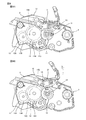
図3から図9を参照して、第1実施形態の現像カートリッジ10について説明する。なお、現像カートリッジ10において、上記した現像カートリッジ1と同様の部材には、同じ符号を付し、説明を省略する。
[First Embodiment]
1. Developer cartridge 10 of the first embodiment
The developing cartridge 10 of the first embodiment will be described with reference to FIGS. In the developing cartridge 10, the same members as those in the developing cartridge 1 described above are denoted by the same reference numerals and description thereof is omitted.

現像カートリッジ10は、図3および図4に示すように、上記した筐体2、現像ローラ3およびアジテータ4に加え、カップリング11と、アジテータギア12と、アイドルギア13と、第1ギア14と、第2ギア15と、突起16と、ギアカバー17とを備える。   As shown in FIGS. 3 and 4, the developing cartridge 10 includes a coupling 11, an agitator gear 12, an idle gear 13, a first gear 14, in addition to the casing 2, the developing roller 3, and the agitator 4. The second gear 15, the protrusion 16, and the gear cover 17 are provided.

1.1 カップリング11
カップリング11は、所定の方向において、筐体2の一方側の外面に位置する。カップリング11は、所定の方向に延びる軸について回転可能である。カップリング11は、継手11Aと、カップリングギア11Bとを備える。
1.1 Coupling 11
The coupling 11 is located on the outer surface on one side of the housing 2 in a predetermined direction. The coupling 11 is rotatable about an axis extending in a predetermined direction. The coupling 11 includes a joint 11A and a coupling gear 11B.

継手11Aは、現像カートリッジ1が画像形成装置に装着されたときに、画像形成装置から駆動力を受けるための構成である。継手11Aは、所定の方向において、カップリング11の一方側の端部に位置する。継手11Aは、所定の方向において、カップリングギア11Bに対して筐体2の反対側に位置する。継手11Aは、画像形成装置の駆動入力部と係合可能である。継手11Aが画像形成装置の駆動入力部と係合することにより、カップリング11は、画像形成装置の駆動入力部から駆動力を受けることが可能となる。   The joint 11A is configured to receive a driving force from the image forming apparatus when the developing cartridge 1 is mounted on the image forming apparatus. The joint 11A is located at an end portion on one side of the coupling 11 in a predetermined direction. The joint 11A is located on the opposite side of the housing 2 with respect to the coupling gear 11B in a predetermined direction. The joint 11A can be engaged with a drive input unit of the image forming apparatus. The coupling 11A engages with the drive input unit of the image forming apparatus, so that the coupling 11 can receive a driving force from the drive input unit of the image forming apparatus.

カップリングギア11Bは、所定の方向において、継手11Aと筐体2との間に位置する。カップリングギア11Bは、継手11Aとともに回転可能である。カップリングギア11Bは、複数のギア歯を有する。複数のギア歯は、カップリングギア11Bの周面に設けられる。   The coupling gear 11B is located between the joint 11A and the housing 2 in a predetermined direction. The coupling gear 11B can rotate together with the joint 11A. The coupling gear 11B has a plurality of gear teeth. The plurality of gear teeth are provided on the peripheral surface of the coupling gear 11B.

なお、現像カートリッジ1は、カップリングギア11Bと接続される図示しないギア列を備える。図示しないギア列は、所定の方向において、筐体2の一方側の外面に位置し、現像ローラ3およびアジテータ4に駆動力を伝える。   The developing cartridge 1 includes a gear train (not shown) connected to the coupling gear 11B. A gear train (not shown) is located on the outer surface on one side of the housing 2 in a predetermined direction, and transmits driving force to the developing roller 3 and the agitator 4.

1.2 アジテータギア12
図4、図5および図6に示すように、アジテータギア12は、所定の方向において、筐体2の他方側の外面に位置する。アジテータギア12は、所定の方向において、筐体2に対して、カップリング11(図3参照)と反対側に位置する。アジテータギア12は、アジテータシャフト4Aに取り付けられる。アジテータシャフト4Aは、所定の方向において、一端部と、他端部とを備える。他端部は、所定の方向において、一端部よりもカップリング11から離れている。詳しくは、アジテータギア12は、アジテータシャフト4Aの他端部に取り付けられる。アジテータギア12は、アジテータシャフト4Aとともに回転可能である。これにより、アジテータギア12は、画像形成装置からの駆動力を受けて回転可能である。詳しくは、画像形成装置からカップリング11(図3参照)に入力された駆動力は、カップリングギア11Bと接続される図示しないギア列を介して、アジテータシャフト4Aに伝わり、さらに、アジテータシャフト4Aを介して、アジテータギア12に伝わる。これにより、アジテータギア12は、画像形成装置からの駆動力を受けて回転する。アジテータギア12は、アジテータギア12の周囲に、複数のギア歯12Aを有する。複数のギア歯12Aは、アジテータギア12の回転方向に並ぶ。さらに、アジテータギア12は、シャフト21を備える。シャフト21は、アジテータギア12の径方向において、アジテータギア12の中央に位置する。シャフト21は、所定の方向において、アジテータギア12の複数のギア歯12Aに対して、筐体2の反対側に位置する。シャフト21は、所定の方向に延びる。シャフト21には、第1ギア14が取り付けられる。
1.2 Agitator gear 12
As shown in FIGS. 4, 5, and 6, the agitator gear 12 is located on the outer surface of the other side of the housing 2 in a predetermined direction. The agitator gear 12 is located on the side opposite to the coupling 11 (see FIG. 3) with respect to the housing 2 in a predetermined direction. The agitator gear 12 is attached to the agitator shaft 4A. The agitator shaft 4A includes one end and the other end in a predetermined direction. The other end is farther from the coupling 11 than the one end in a predetermined direction. Specifically, the agitator gear 12 is attached to the other end of the agitator shaft 4A. The agitator gear 12 can rotate together with the agitator shaft 4A. Thereby, the agitator gear 12 can be rotated by receiving a driving force from the image forming apparatus. Specifically, the driving force input from the image forming apparatus to the coupling 11 (see FIG. 3) is transmitted to the agitator shaft 4A through a gear train (not shown) connected to the coupling gear 11B, and further, the agitator shaft 4A. Is transmitted to the agitator gear 12. As a result, the agitator gear 12 rotates upon receiving a driving force from the image forming apparatus. The agitator gear 12 has a plurality of gear teeth 12 </ b> A around the agitator gear 12. The plurality of gear teeth 12 </ b> A are arranged in the rotational direction of the agitator gear 12. Further, the agitator gear 12 includes a shaft 21. The shaft 21 is located at the center of the agitator gear 12 in the radial direction of the agitator gear 12. The shaft 21 is located on the opposite side of the housing 2 with respect to the plurality of gear teeth 12A of the agitator gear 12 in a predetermined direction. The shaft 21 extends in a predetermined direction. A first gear 14 is attached to the shaft 21.

1.3 アイドルギア13
アイドルギア13は、アジテータギア12から第1ギア14へ駆動力を伝えるためのギアである。アイドルギア13は、所定の方向において、筐体2の他方側の外面に位置する。アイドルギア13は、所定の方向において、筐体2に対して、カップリング11(図3参照)と反対側に位置する。アイドルギア13は、貫通穴13Cを有する。貫通穴13Cは、所定の方向において、アイドルギア13を貫通する。貫通穴13Cには、筐体2の他方側の外面に設けられるシャフト22が挿入される。これにより、アイドルギア13は、シャフト22に取り付けられる。アイドルギア13は、シャフト22について回転可能である。アイドルギア13は、大径ギア13Aと、小径ギア13Bとを備える。大径ギア13Aと小径ギア13Bとは、一体的に構成される。大径ギア13Aと小径ギア13Bとは、所定の方向に並ぶ。小径ギア13Bは、所定の方向において、大径ギア13Aに対して、筐体2の反対側に位置する。
1.3 Idle gear 13
The idle gear 13 is a gear for transmitting a driving force from the agitator gear 12 to the first gear 14. The idle gear 13 is located on the outer surface of the other side of the housing 2 in a predetermined direction. The idle gear 13 is located on the side opposite to the coupling 11 (see FIG. 3) with respect to the housing 2 in a predetermined direction. The idle gear 13 has a through hole 13C. The through hole 13C penetrates the idle gear 13 in a predetermined direction. A shaft 22 provided on the outer surface of the other side of the housing 2 is inserted into the through hole 13C. Thereby, the idle gear 13 is attached to the shaft 22. The idle gear 13 can rotate about the shaft 22. The idle gear 13 includes a large diameter gear 13A and a small diameter gear 13B. The large diameter gear 13A and the small diameter gear 13B are integrally configured. The large diameter gear 13A and the small diameter gear 13B are arranged in a predetermined direction. The small diameter gear 13B is located on the opposite side of the housing 2 with respect to the large diameter gear 13A in a predetermined direction.

大径ギア13Aは、大径ギア13Aの周囲に、複数のギア歯を有する。複数のギア歯は、アイドルギア13の回転方向に並ぶ。大径ギア13Aは、アジテータギア12と噛み合う。詳しくは、大径ギア13Aの複数のギア歯は、アジテータギア12の複数のギア歯12Aと噛み合う。これにより、アイドルギア13は、アジテータギア12から駆動力を受けて回転可能である。   The large diameter gear 13A has a plurality of gear teeth around the large diameter gear 13A. The plurality of gear teeth are arranged in the rotational direction of the idle gear 13. The large diameter gear 13 </ b> A meshes with the agitator gear 12. Specifically, the plurality of gear teeth of the large diameter gear 13 </ b> A mesh with the plurality of gear teeth 12 </ b> A of the agitator gear 12. As a result, the idle gear 13 can be rotated by receiving a driving force from the agitator gear 12.

小径ギア13Bは、小径ギア13Bの周囲に、複数のギア歯を有する。複数のギア歯は、アイドルギア7の回転方向に並ぶ。小径ギア13Bの歯先円の径は、大径ギア13Aの歯先円の径よりも小さい。小径ギア13Bのギア歯の数は、大径ギア13Aのギア歯の数よりも少ない。小径ギア13Bは、第1ギア14の後述する小径ギア14Aと噛み合う。詳しくは、小径ギア13Bの複数のギア歯は、小径ギア14Aの複数のギア歯14Eと噛み合う。これにより、小径ギア13Bは、第1ギア14に駆動力を伝えることができる。   The small diameter gear 13B has a plurality of gear teeth around the small diameter gear 13B. The plurality of gear teeth are arranged in the rotational direction of the idle gear 7. The diameter of the tip circle of the small diameter gear 13B is smaller than the diameter of the tip circle of the large diameter gear 13A. The number of gear teeth of the small diameter gear 13B is smaller than the number of gear teeth of the large diameter gear 13A. The small diameter gear 13B meshes with a small diameter gear 14A, which will be described later, of the first gear 14. Specifically, the plurality of gear teeth of the small diameter gear 13B mesh with the plurality of gear teeth 14E of the small diameter gear 14A. Thereby, the small diameter gear 13 </ b> B can transmit the driving force to the first gear 14.

1.4 第1ギア14
第1ギア14は、所定の方向において、アジテータギア12の複数のギア歯12Aに対して、筐体2の反対側に位置する。第1ギア14は、貫通穴14Cを有する。貫通穴14Cは、所定の方向において、第1ギア14を貫通する。貫通穴14Cには、アジテータギア12のシャフト21が挿入される。これにより、第1ギア14は、シャフト21に取り付けられる。第1ギア14は、シャフト21について回転可能である。第1ギア14は、所定の方向に延びる第1軸A1について回転可能である。第1ギア14は、小径ギア14Aと、大径ギア14Bとを備える。小径ギア14Aと大径ギア14Bとは、一体的に構成される。小径ギア14Aと大径ギア14Bとは、所定の方向に並ぶ。大径ギア14Bは、所定の方向において、小径ギア14Aに対して、筐体2の反対側に位置する。
1.4 First gear 14
The first gear 14 is located on the opposite side of the housing 2 with respect to the plurality of gear teeth 12A of the agitator gear 12 in a predetermined direction. The first gear 14 has a through hole 14C. The through hole 14C penetrates the first gear 14 in a predetermined direction. The shaft 21 of the agitator gear 12 is inserted into the through hole 14C. Thereby, the first gear 14 is attached to the shaft 21. The first gear 14 is rotatable about the shaft 21. The first gear 14 is rotatable about a first axis A1 extending in a predetermined direction. The first gear 14 includes a small diameter gear 14A and a large diameter gear 14B. The small diameter gear 14A and the large diameter gear 14B are integrally formed. The small diameter gear 14A and the large diameter gear 14B are arranged in a predetermined direction. The large diameter gear 14B is located on the opposite side of the housing 2 with respect to the small diameter gear 14A in a predetermined direction.

小径ギア14Aは、アイドルギア13の小径ギア13Bと噛み合う。詳しくは、小径ギア14Aは、小径ギア14Aの周囲の一部に、複数のギア歯14Eを有する。小径ギア14Aの複数のギア歯14Eは、小径ギア13Bの複数のギア歯と噛み合う。また、小径ギア14Aは、複数のギア歯14Eが設けられていない欠け歯部分14Dを有する。複数のギア歯14Eは、第1ギア14の回転方向に並ぶ。欠け歯部分14Dは、第1ギア14の回転方向において、複数のギア歯14Eと並ぶ。第1ギア14の回転方向において、欠け歯部分14Dの長さは、複数のギア歯14Eと、小径ギア13Bの複数のギア歯との噛み合いが解除されるような長さである。第1ギア14は、小径ギア14Aの複数のギア歯14Eが、小径ギア13Bの複数のギア歯と噛み合っている間、小径ギア13Bから駆動力を受けることができる。これにより、第1ギア14は、アイドルギア13を介して、アジテータギア12からの駆動力を受けて回転可能である。また、第1ギア14は、小径ギア14Aと小径ギア13Bとが噛み合い始める第1位置(図7A参照)から、小径ギア14Aと小径ギア13Bとの噛み合いが解除される第2位置(図9参照)まで回転可能である。なお、小径ギア14Aと小径ギア13Bとが噛み合い始めるとは、小径ギア13Bの複数のギア歯の1つが、小径ギア14Aの複数のギア歯14Eのうち、第1ギア14の回転方向における最も下流側のギア歯に接触することをいう。また、小径ギア14Aと小径ギア13Bとの噛み合いが解除されるとは、第1ギア14の回転方向において、小径ギア14Aの複数のギア歯14Eのうちの最も上流側のギア歯が、小径ギア14Aから離れることをいう。つまり、第1ギア14が第2位置のときに、第1ギア14は、アイドルギア13の複数のギア歯のいずれのギア歯とも噛み合わない。小径ギア14Aが有する複数のギア歯14Eの歯数は、後述する第2ギア15が有する複数のギア歯の歯数の1.5倍以上である。これにより、後述する第2ギア15は、第1ギア14が第1位置から第2位置まで回転する間に、1.5回以上、回転可能である。また、小径ギア14Aの歯先円の径は、第2ギア15の歯先円の径の1.5倍以上である。   The small diameter gear 14 </ b> A meshes with the small diameter gear 13 </ b> B of the idle gear 13. Specifically, the small diameter gear 14A has a plurality of gear teeth 14E in a part of the periphery of the small diameter gear 14A. The plurality of gear teeth 14E of the small diameter gear 14A mesh with the plurality of gear teeth of the small diameter gear 13B. The small-diameter gear 14A has a missing tooth portion 14D that is not provided with a plurality of gear teeth 14E. The plurality of gear teeth 14 </ b> E are arranged in the rotation direction of the first gear 14. The missing tooth portion 14D is aligned with the plurality of gear teeth 14E in the rotation direction of the first gear 14. In the rotation direction of the first gear 14, the length of the missing tooth portion 14D is such that the meshing between the plurality of gear teeth 14E and the plurality of gear teeth of the small-diameter gear 13B is released. The first gear 14 can receive a driving force from the small diameter gear 13B while the plurality of gear teeth 14E of the small diameter gear 14A are engaged with the plurality of gear teeth of the small diameter gear 13B. As a result, the first gear 14 can rotate by receiving a driving force from the agitator gear 12 via the idle gear 13. Further, the first gear 14 is moved from the first position (see FIG. 7A) where the small diameter gear 14A and the small diameter gear 13B start to be engaged to the second position (see FIG. 9) where the engagement between the small diameter gear 14A and the small diameter gear 13B is released. ). Note that when the small diameter gear 14A and the small diameter gear 13B start to mesh, one of the plurality of gear teeth of the small diameter gear 13B is the most downstream in the rotation direction of the first gear 14 among the plurality of gear teeth 14E of the small diameter gear 14A. Contacting the side gear teeth. Further, when the meshing between the small diameter gear 14A and the small diameter gear 13B is released, the most upstream gear tooth among the plurality of gear teeth 14E of the small diameter gear 14A in the rotational direction of the first gear 14 is the small diameter gear. It means leaving 14A. That is, when the first gear 14 is in the second position, the first gear 14 does not mesh with any of the plurality of gear teeth of the idle gear 13. The number of teeth of the plurality of gear teeth 14E included in the small diameter gear 14A is 1.5 times or more the number of teeth of the plurality of gear teeth included in the second gear 15 described later. As a result, the second gear 15 described later can rotate 1.5 times or more while the first gear 14 rotates from the first position to the second position. Further, the diameter of the tip circle of the small-diameter gear 14 </ b> A is 1.5 times or more the diameter of the tip circle of the second gear 15.

大径ギア14Bは、大径ギア14Bの周囲に、複数のギア歯を有する。複数のギア歯は、第1ギア14の回転方向に並ぶ。大径ギア13Aの歯先円の径は、小径ギア13Bの歯先円の径よりも大きい。   The large diameter gear 14B has a plurality of gear teeth around the large diameter gear 14B. The plurality of gear teeth are arranged in the rotation direction of the first gear 14. The diameter of the tip circle of the large-diameter gear 13A is larger than the diameter of the tip circle of the small-diameter gear 13B.

1.5 第2ギア15
第2ギア15は、所定の方向において、筐体2の他方側の外面に位置する。第2ギア15は、所定の方向において、筐体2に対して、カップリング11(図3参照)と反対側に位置する。第2ギア15は、貫通穴15Aを有する。貫通穴15Aは、所定の方向において、第2ギア15を貫通する。貫通穴15Aには、筐体2の他方側の外面に設けられるシャフト23が挿入される。第2ギア15は、シャフト23に取り付けられる。第2ギア15は、第2ギア15の周囲に、複数のギア歯15Bを有する。複数のギア歯15Bは、第2ギア15の回転方向に並ぶ。第2ギア15は、大径ギア14Bと噛み合う。詳しくは、第2ギア15の複数のギア歯15Bは、大径ギア14Bの複数のギア歯と噛み合う。これにより、第2ギア15は、第1ギア14から駆動力を受けて、シャフト23について回転可能である。第2ギア15は、所定の方向に延びる第2軸A2について回転可能である。
1.5 Second gear 15
The second gear 15 is located on the outer surface of the other side of the housing 2 in a predetermined direction. The second gear 15 is located on the side opposite to the coupling 11 (see FIG. 3) with respect to the housing 2 in a predetermined direction. The second gear 15 has a through hole 15A. The through hole 15A penetrates the second gear 15 in a predetermined direction. A shaft 23 provided on the outer surface of the other side of the housing 2 is inserted into the through hole 15A. The second gear 15 is attached to the shaft 23. The second gear 15 has a plurality of gear teeth 15 </ b> B around the second gear 15. The plurality of gear teeth 15 </ b> B are arranged in the rotation direction of the second gear 15. The second gear 15 meshes with the large diameter gear 14B. Specifically, the plurality of gear teeth 15B of the second gear 15 mesh with the plurality of gear teeth of the large-diameter gear 14B. As a result, the second gear 15 is rotatable about the shaft 23 by receiving a driving force from the first gear 14. The second gear 15 is rotatable about a second axis A2 extending in a predetermined direction.

1.6 突起16
突起16は、所定の方向において、第2ギア15に対して、筐体2の反対側に位置する。突起16は、貫通穴15Aの周囲に位置する。突起16は、所定の方向に延びる。突起16は、所定方向において、第2ギア15から延びる。すなわち、突起16は、第2ギア15と一体的に構成される。これにより、突起9は、第2ギア8とともに、シャフト23について回転可能である。突起16は、具体的には、1つ設けられる。なお、突起16は、後述する変形例でも説明するように、複数、設けられてもよい。
1.6 Protrusion 16
The protrusion 16 is located on the opposite side of the housing 2 with respect to the second gear 15 in a predetermined direction. The protrusion 16 is located around the through hole 15A. The protrusion 16 extends in a predetermined direction. The protrusion 16 extends from the second gear 15 in a predetermined direction. That is, the protrusion 16 is configured integrally with the second gear 15. Thereby, the protrusion 9 can rotate about the shaft 23 together with the second gear 8. Specifically, one protrusion 16 is provided. Note that a plurality of protrusions 16 may be provided as will be described later in a modification.

1.7 ギアカバー17
ギアカバー17は、図3に示すように、所定の方向において、筐体2に対して、カップリング11と反対側に位置する。ギアカバー17は、所定の方向において、筐体2の他方側の外面に取り付けられる。ギアカバー17は、アジテータギア12、アイドルギア13、第1ギア14および第2ギア15を覆う。ギアカバー17は、開口24を有する。開口24は、所定の方向と交差する方向において、ギアカバー17の壁を貫通する。突起16およびシャフト23は、開口24から露出する。これにより、突起16は、シャフト23について回転したときに、開口24を通過することができる。なお、突起16が開口24を通過するとは、突起16が、シャフト23について回転しつつ、開口24を介して、一旦、ギアカバー17の外側に出た後、開口24を介して、ギアカバー17の内側に入ることをいう。
1.7 Gear cover 17
As shown in FIG. 3, the gear cover 17 is located on the opposite side of the coupling 11 with respect to the housing 2 in a predetermined direction. The gear cover 17 is attached to the outer surface of the other side of the housing 2 in a predetermined direction. The gear cover 17 covers the agitator gear 12, the idle gear 13, the first gear 14, and the second gear 15. The gear cover 17 has an opening 24. The opening 24 penetrates the wall of the gear cover 17 in a direction intersecting with a predetermined direction. The protrusion 16 and the shaft 23 are exposed from the opening 24. This allows the protrusion 16 to pass through the opening 24 when rotated about the shaft 23. Note that the projection 16 passes through the opening 24, the projection 16 rotates about the shaft 23, and once out of the gear cover 17 through the opening 24, then the gear cover 17 through the opening 24. To go inside.

2.現像カートリッジ10の動作
次いで、図7Aから図10を参照して、現像カートリッジ10の動作について説明する。
2. Operation of Developing Cartridge 10 Next, the operation of the developing cartridge 10 will be described with reference to FIGS. 7A to 10.

現像カートリッジ10が画像形成装置に装着されると、図7Aに示すように、画像形成装置に設けられるアクチュエータ31が、シャフト23に接触する。図7Aに示すアクチュエータ31の位置を、接触位置と定義する。また、このとき、第1ギア14は、第1位置に位置している。   When the developing cartridge 10 is attached to the image forming apparatus, the actuator 31 provided in the image forming apparatus contacts the shaft 23 as shown in FIG. 7A. The position of the actuator 31 shown in FIG. 7A is defined as a contact position. At this time, the first gear 14 is located at the first position.

次いで、画像形成装置の駆動入力部からカップリング11(図3参照)に駆動力が入力されると、駆動力は、カップリング11から図示しないギア列およびアジテータシャフト4Aを介してアジテータギア12に伝わる。これにより、アジテータギア12、および、アジテータギア12に噛み合うアイドルギア13が、回転する。すると、アイドルギア13から駆動力を受けて、第1ギア14が回転する。第1ギア14が回転し始める時点を、t(図10参照)と定義する。 Next, when a driving force is input to the coupling 11 (see FIG. 3) from the driving input unit of the image forming apparatus, the driving force is transmitted from the coupling 11 to the agitator gear 12 via a gear train (not shown) and the agitator shaft 4A. It is transmitted. As a result, the agitator gear 12 and the idle gear 13 that meshes with the agitator gear 12 rotate. Then, receiving the driving force from the idle gear 13, the first gear 14 rotates. The time point at which the first gear 14 starts to rotate is defined as t 0 (see FIG. 10).

第1ギア14が回転すると、第1ギア14から駆動力を受けて、第2ギア15が回転する。すると、突起16が、第2ギア15とともに回転し、シャフト23の周面に沿って移動する。このとき、突起16は、開口24(図3参照)を介して、ギアカバー17の外に出る。   When the first gear 14 rotates, the second gear 15 rotates by receiving a driving force from the first gear 14. Then, the protrusion 16 rotates with the second gear 15 and moves along the peripheral surface of the shaft 23. At this time, the protrusion 16 goes out of the gear cover 17 through the opening 24 (see FIG. 3).

すると、突起16は、時点t(図10参照)において、画像形成装置のアクチュエータ31と当接し、アクチュエータ31を、シャフト23から離れる方向へ押圧する。すると、アクチュエータ31は、接触位置から、シャフト23から離れる方向へ移動し、図7Bに示す離間位置に位置する。 Then, the protrusion 16 contacts the actuator 31 of the image forming apparatus at time t 1 (see FIG. 10), and presses the actuator 31 in a direction away from the shaft 23. Then, the actuator 31 moves from the contact position in a direction away from the shaft 23, and is located at the separation position shown in FIG. 7B.

次いで、さらに第1ギア14が回転すると、突起16は、シャフト23とアクチュエータ31との間を通過し、時点t(図10参照)において、アクチュエータ31から離れる。すると、アクチュエータ31は、離間位置から接触位置へ移動し、図8Aに示すように、接触位置に位置する。その後、突起16は、開口24(図3参照)を介して、ギアカバー17の内側に入る。これにより、突起16は、開口24を1回通過する。また、突起16は、開口24を1回通過する間に、アクチュエータ31を、接触位置から離間位置へ、1回動かす。 Next, when the first gear 14 further rotates, the protrusion 16 passes between the shaft 23 and the actuator 31 and moves away from the actuator 31 at time t 2 (see FIG. 10). Then, the actuator 31 moves from the separated position to the contact position, and is located at the contact position as shown in FIG. 8A. Thereafter, the protrusion 16 enters the inside of the gear cover 17 through the opening 24 (see FIG. 3). Thereby, the protrusion 16 passes through the opening 24 once. Further, the protrusion 16 moves the actuator 31 once from the contact position to the separated position while passing through the opening 24 once.

次いで、さらに第1ギア14が回転すると、図8Bに示すように、時点tから時点t(図10参照)において、突起16が、再び、シャフト23とアクチュエータ31との間を通過する。このとき、突起16は、再び、開口24を1回通過する。すなわち、突起16は、第2ギア15とともに回転している間に、開口24を1回通過した後、さらに、少なくとも1回、開口24を通過する。これにより、アクチュエータ31は、時点tにおいて、接触位置から離間位置に移動し、時点tから時点tの間、離間位置に位置した後、時点tにおいて、離間位置から接触位置に移動する。 Next, when the first gear 14 further rotates, as shown in FIG. 8B, the protrusion 16 again passes between the shaft 23 and the actuator 31 from the time point t 3 to the time point t 4 (see FIG. 10). At this time, the protrusion 16 passes through the opening 24 once again. That is, the protrusion 16 passes through the opening 24 once after passing through the opening 24 while rotating together with the second gear 15. This movement, the actuator 31, at time t 3, moves to the separated position from the contact position, between the time t 3 of the time t 4, after located in spaced position, at time t 4, the contact position from the spaced position To do.

その後、図9に示すように、時点t(図10参照)において、第1ギア14の欠け歯部分14Dが、アイドルギア13の小径ギア13Bと向かい合う。これにより、小径ギア14Aと小径ギア13Bとの噛み合いが解除され、第1ギア14の回転が停止する。すると、第2ギア15および突起16の回転が停止する。詳しくは、第2ギア15は、第1ギア14が第1位置から第2位置まで回転する間、回転した後、第1ギア14とアイドルギア7との噛み合いが解除されることにより、停止する。これにより、突起16は、第1ギア14が第1位置から第2位置まで回転する間、第2ギア15とともに回転し、第2ギア15が停止することにより停止する。 Thereafter, as shown in FIG. 9, the missing tooth portion 14 </ b> D of the first gear 14 faces the small-diameter gear 13 </ b> B of the idle gear 13 at time t 5 (see FIG. 10). Thereby, the meshing of the small diameter gear 14A and the small diameter gear 13B is released, and the rotation of the first gear 14 is stopped. Then, the rotation of the second gear 15 and the protrusion 16 stops. Specifically, the second gear 15 stops when the first gear 14 is rotated from the first position to the second position and then the meshing between the first gear 14 and the idle gear 7 is released. . Thereby, the protrusion 16 rotates together with the second gear 15 while the first gear 14 rotates from the first position to the second position, and stops when the second gear 15 stops.

なお、画像形成装置は、現像カートリッジ10が画像形成装置に装着された後、所定の時間内に、アクチュエータ31が、2回、離間位置に位置したことを検知した場合、例えば、現像カートリッジ10が新品であると判断する。   Note that when the image forming apparatus detects that the actuator 31 is positioned twice in a predetermined time after the developing cartridge 10 is mounted on the image forming apparatus, for example, the developing cartridge 10 is Judged to be new.

また、画像形成装置は、現像カートリッジ10が画像形成装置に装着された後、所定の時間、アクチュエータ31が離間位置に位置しなかった場合、現像カートリッジ10が旧品であると判断する。   Further, the image forming apparatus determines that the developing cartridge 10 is an old product if the actuator 31 is not positioned in the separated position for a predetermined time after the developing cartridge 10 is mounted on the image forming apparatus.

3.作用効果
突起16は、図7Aから図9に示すように、第1ギア14が第1位置(図7A参照)から第2位置(図9参照)まで回転する間、第2ギア15とともに回転し、開口24(図3参照)を1回通過した後、さらに、少なくとも1回、開口24を通過する。その後、突起16は、第2ギア15が停止することにより停止する。
3. As shown in FIGS. 7A to 9, the projection 16 rotates together with the second gear 15 while the first gear 14 rotates from the first position (see FIG. 7A) to the second position (see FIG. 9). After passing once through the opening 24 (see FIG. 3), it passes through the opening 24 at least once more. Thereafter, the protrusion 16 stops when the second gear 15 stops.

これにより、1つの突起16が開口24を通過する回数を変更して、突起16が回転することにより形成される信号パターンを、容易に増加させることができる。   As a result, the number of times one protrusion 16 passes through the opening 24 can be changed, and the signal pattern formed by the rotation of the protrusion 16 can be easily increased.

4.変形例
上記した第1実施形態において、1つの突起16が開口24を通過する回数は、例えば、第1ギア14と第2ギア15とのギア比を調整するなどにより、容易に変更できる。1つの突起16が開口24を通過する回数は、例えば、3回でもよいし、4回でもよい。
4). Modified Example In the first embodiment described above, the number of times one protrusion 16 passes through the opening 24 can be easily changed by adjusting the gear ratio between the first gear 14 and the second gear 15, for example. The number of times that one protrusion 16 passes through the opening 24 may be three times or four times, for example.

上記した第1実施形態において、突起16の数および形状は、特に限定されない。例えば、突起16の数は、図11Aに示すように、2つでもよい。2つの突起16は、第2ギア15の回転方向において、互いに離れている。   In the first embodiment described above, the number and shape of the protrusions 16 are not particularly limited. For example, the number of protrusions 16 may be two as shown in FIG. 11A. The two protrusions 16 are separated from each other in the rotation direction of the second gear 15.

この場合、図12Aに示すように、第1の突起16が時間T1の間、アクチュエータ31を離間位置に位置させた後、第2の突起16が時間T2の間、アクチュエータ31を離間位置に位置させる。その後、再び、第1の突起16が時間T1の間、アクチュエータ31を離間位置に位置させた後、第2の突起16が時間T2の間、アクチュエータ31を離間位置に位置させる。   In this case, as shown in FIG. 12A, after the first protrusion 16 has positioned the actuator 31 in the separated position for the time T1, the second protrusion 16 has positioned the actuator 31 in the separated position for the time T2. Let Thereafter, again, the first protrusion 16 positions the actuator 31 in the separated position for the time T1, and then the second protrusion 16 positions the actuator 31 in the separated position for the time T2.

また、図11Bおよび図12Bに示すように、突起16の数が3つである場合も同様である。3つの突起16は、第2ギア15の回転方向において、互いに離れている。第2の突起16が時間T2の間、アクチュエータ31を離間位置に位置させた後、第3の突起16が時間T3の間、アクチュエータ31を離間位置に位置させる。   The same applies to the case where the number of the protrusions 16 is three as shown in FIGS. 11B and 12B. The three protrusions 16 are separated from each other in the rotation direction of the second gear 15. After the second protrusion 16 positions the actuator 31 in the separated position during time T2, the third protrusion 16 positions the actuator 31 in the separated position during time T3.

また、図11Cおよび図12Cに示すように、突起16Aと、第2ギア15の回転方向において突起16Aよりも長い突起16Bを備えてもよい。突起16Aと突起16Bとは、第2ギア15の回転方向において、互いに離れている。この場合、図11Aに示す突起16と比べて、突起16Bとの接触によってアクチュエータ31が離間位置に位置する時間T2が、長くなる。これにより、画像形成装置は、例えば、時間T2が短い場合には、現像剤の収容量が少ない仕様の現像カートリッジであると判断し、時間T2が長い場合には、現像剤の収容量が多い仕様の現像カートリッジであると判断することもできる。   11C and 12C, a protrusion 16A and a protrusion 16B longer than the protrusion 16A in the rotation direction of the second gear 15 may be provided. The protrusion 16 </ b> A and the protrusion 16 </ b> B are separated from each other in the rotation direction of the second gear 15. In this case, as compared with the protrusion 16 shown in FIG. 11A, the time T2 at which the actuator 31 is located at the separated position by the contact with the protrusion 16B becomes longer. As a result, for example, when the time T2 is short, the image forming apparatus determines that the developer cartridge has a specification with a small amount of developer, and when the time T2 is long, the amount of developer is large. It can also be determined that the developing cartridge has specifications.

また、図11Dおよび図12Dに示すように、第2ギア15の回転方向に延びる1つの突起16を備えてもよい。この場合、図5に示す突起16と比べて、アクチュエータ31が離間位置に位置する時間T1が長くなる。図11Cおよび図12Cに示す場合と同様に、画像形成装置は、例えば、時間T1が短い場合には、現像剤の収容量が少ない仕様の現像カートリッジであると判断し、時間T1が長い場合には、現像剤の収容量が多い仕様の現像カートリッジであると判断することもできる。   Further, as shown in FIGS. 11D and 12D, one protrusion 16 extending in the rotation direction of the second gear 15 may be provided. In this case, as compared with the projection 16 shown in FIG. Similarly to the case shown in FIGS. 11C and 12C, for example, when the time T1 is short, the image forming apparatus determines that the developer cartridge has a specification with a small amount of developer and when the time T1 is long. Can be determined to be a developer cartridge having a large amount of developer.

なお、上記した現像カートリッジ10の新旧や現像剤の収容量は、それぞれ、現像カートリッジ10の情報の一例である。突起16が回転することにより形成される信号パターンは、現像カートリッジ10の新旧や現像剤の収容量だけでなく、必要に応じて、現像カートリッジ10の新旧や現像剤の収容量以外の現像カートリッジ10の情報に対応させることができる。   Note that the above-described new and old development cartridges 10 and developer storage amounts are examples of information on the development cartridge 10. The signal pattern formed by the rotation of the protrusion 16 is not only the new or old of the developing cartridge 10 or the developer capacity, but also the developing cartridge 10 other than the old or new of the developing cartridge 10 or the developer capacity as required. It is possible to correspond to the information of.

[第2実施形態]
図13および図14を参照して、第2実施形態の現像カートリッジ40について説明する。なお、現像カートリッジ40において、現像カートリッジ10と同じ部材には、同じ符号を付し、説明を省略する。
[Second Embodiment]
With reference to FIGS. 13 and 14, the developing cartridge 40 of the second embodiment will be described. In the developing cartridge 40, the same members as those in the developing cartridge 10 are denoted by the same reference numerals, and description thereof is omitted.

現像カートリッジ40では、アジテータギア41、アイドルギア42、第1ギア43、第2ギア44、および、2つの突起45は、所定の方向において、筐体2の一方側の外面に位置する。すなわち、アジテータギア41、アイドルギア42、第1ギア43、第2ギア44、および、2つの突起45は、所定の方向において、筐体2に対して、カップリング11と同じ側に位置する。   In the developing cartridge 40, the agitator gear 41, the idle gear 42, the first gear 43, the second gear 44, and the two protrusions 45 are located on the outer surface on one side of the housing 2 in a predetermined direction. That is, the agitator gear 41, the idle gear 42, the first gear 43, the second gear 44, and the two protrusions 45 are located on the same side as the coupling 11 with respect to the housing 2 in a predetermined direction.

アジテータギア41は、アジテータシャフト4Aの一方側の端部に取り付けられる。アジテータギア41は、アジテータシャフト4Aとともに回転可能である。アジテータギア41は、アイドルギア46を介して、カップリング11からの駆動力を受けることができる。これにより、アジテータギア41は、画像形成装置からの駆動力を受けて回転可能である。   The agitator gear 41 is attached to one end of the agitator shaft 4A. The agitator gear 41 can rotate together with the agitator shaft 4A. The agitator gear 41 can receive a driving force from the coupling 11 via the idle gear 46. As a result, the agitator gear 41 can rotate by receiving a driving force from the image forming apparatus.

アイドルギア42は、アジテータギア41から第1ギア43へ駆動力を伝えるためのギアである。アイドルギア42は、筐体2の一方側の外面に設けられるシャフト52に取り付けられる。アイドルギア42は、シャフト52について回転可能である。アイドルギア42は、大径ギア42Aと、小径ギア42Bとを備える。小径ギア42Bは、大径ギア42Aの歯先円の径よりも小さい歯先円を有する。小径ギア42Bのギア歯の数は、大径ギア42Aのギア歯の数よりも少ない。大径ギア42Aと小径ギア42Bとは、一体的に構成される。大径ギア42Aと小径ギア42Bとは、所定の方向に並ぶ。小径ギア42Bは、所定の方向において、大径ギア42Aに対して、筐体2の反対側に位置する。大径ギア42Aは、アジテータギア41と噛み合う。これにより、アイドルギア42は、アジテータギア41から駆動力を受けて回転可能である。小径ギア42Bは、第1ギア43と噛み合う。これにより、小径ギア42Bは、第1ギア43に駆動力を伝えることができる。   The idle gear 42 is a gear for transmitting a driving force from the agitator gear 41 to the first gear 43. The idle gear 42 is attached to a shaft 52 provided on the outer surface on one side of the housing 2. The idle gear 42 can rotate about the shaft 52. The idle gear 42 includes a large diameter gear 42A and a small diameter gear 42B. The small diameter gear 42B has a tooth tip circle smaller than the diameter of the tooth tip circle of the large diameter gear 42A. The number of gear teeth of the small diameter gear 42B is smaller than the number of gear teeth of the large diameter gear 42A. The large diameter gear 42A and the small diameter gear 42B are integrally formed. The large diameter gear 42A and the small diameter gear 42B are arranged in a predetermined direction. The small diameter gear 42B is located on the opposite side of the housing 2 with respect to the large diameter gear 42A in a predetermined direction. The large diameter gear 42 </ b> A meshes with the agitator gear 41. As a result, the idle gear 42 can rotate by receiving a driving force from the agitator gear 41. The small diameter gear 42 </ b> B meshes with the first gear 43. Thereby, the small diameter gear 42 </ b> B can transmit the driving force to the first gear 43.

第1ギア43は、筐体2の一方側の外面に設けられるシャフト53に取り付けられる。第1ギア43は、シャフト53について回転可能である。これにより、第1ギア43は、所定の方向に延びる第1軸A1について回転可能である。第1ギア43は、アイドルギア42の小径ギア42Bと噛み合う。第1ギア43は、第1ギア43の周囲の一部に、複数のギア歯43Aを有する。複数のギア歯43Aは、第1ギア43の回転方向に並ぶ。複数のギア歯43Aは、小径ギア42Bの複数のギア歯と噛み合う。また、第1ギア43は、複数のギア歯43Aが設けられていない欠け歯部分43Bを有する。欠け歯部分43Bは、第1ギア43の回転方向において、複数のギア歯43Aと並ぶ。第1ギア43の回転方向において、欠け歯部分43Bの長さは、複数のギア歯43Aと、小径ギア42Bの複数のギア歯との噛み合いが解除されるような長さである。第1ギア43は、第1ギア43の複数のギア歯43Aが、小径ギア42Bの複数のギア歯と噛み合っている間、小径ギア42Bから駆動力を受けることができる。これにより、第1ギア43は、アイドルギア42を介して、アジテータギア41からの駆動力を受けて回転可能である。また、第1ギア43は、小径ギア42Bとが噛み合い始める第1位置(図13参照)から、小径ギア42Bとの噛み合いが解除される第2位置まで回転可能である。第1ギア43が有する複数のギア歯43Aの歯数は、第2ギア44が有する複数のギア歯44Aの歯数の1.5倍以上である。これにより、後述する第2ギア44は、第1ギア43が第1位置から第2位置まで回転する間に、1.5回以上、回転可能である。第1ギア43の歯先円の径は、第2ギア44の歯先円の径の1.5倍以上である。   The first gear 43 is attached to a shaft 53 provided on the outer surface on one side of the housing 2. The first gear 43 is rotatable about the shaft 53. Thereby, the first gear 43 can rotate about the first axis A1 extending in a predetermined direction. The first gear 43 meshes with the small diameter gear 42 </ b> B of the idle gear 42. The first gear 43 has a plurality of gear teeth 43 </ b> A in a part of the periphery of the first gear 43. The plurality of gear teeth 43 </ b> A are arranged in the rotation direction of the first gear 43. The plurality of gear teeth 43A mesh with the plurality of gear teeth of the small diameter gear 42B. Further, the first gear 43 has a missing tooth portion 43B in which a plurality of gear teeth 43A are not provided. The missing tooth portion 43 </ b> B is aligned with the plurality of gear teeth 43 </ b> A in the rotation direction of the first gear 43. In the rotation direction of the first gear 43, the length of the missing tooth portion 43B is such that the meshing between the plurality of gear teeth 43A and the plurality of gear teeth of the small diameter gear 42B is released. The first gear 43 can receive a driving force from the small diameter gear 42B while the plurality of gear teeth 43A of the first gear 43 are engaged with the plurality of gear teeth of the small diameter gear 42B. As a result, the first gear 43 is rotatable by receiving a driving force from the agitator gear 41 via the idle gear 42. Further, the first gear 43 can rotate from a first position (see FIG. 13) where the small diameter gear 42B starts to mesh to a second position where the mesh with the small diameter gear 42B is released. The number of teeth of the plurality of gear teeth 43A included in the first gear 43 is 1.5 times or more the number of teeth of the plurality of gear teeth 44A included in the second gear 44. Thereby, the 2nd gear 44 mentioned later can rotate 1.5 times or more, while the 1st gear 43 rotates from a 1st position to a 2nd position. The diameter of the tip circle of the first gear 43 is 1.5 times or more the diameter of the tip circle of the second gear 44.

第2ギア44は、筐体2の一方側の外面に設けられるシャフト54に取り付けられる。第2ギア44は、第2ギア44の周囲に、複数のギア歯44Aを有する。複数のギア歯44Aは、第2ギア44の回転方向に並ぶ。複数のギア歯44Aは、第1ギア43の複数のギア歯43Aと噛み合う。これにより、第2ギア44は、第1ギア43から駆動力を受けて、シャフト54について回転可能である。第2ギア44は、所定の方向に延びる第2軸A2について回転可能である。   The second gear 44 is attached to a shaft 54 provided on the outer surface on one side of the housing 2. The second gear 44 has a plurality of gear teeth 44 </ b> A around the second gear 44. The plurality of gear teeth 44 </ b> A are arranged in the rotation direction of the second gear 44. The plurality of gear teeth 44 </ b> A mesh with the plurality of gear teeth 43 </ b> A of the first gear 43. As a result, the second gear 44 can rotate about the shaft 54 by receiving a driving force from the first gear 43. The second gear 44 is rotatable about a second axis A2 extending in a predetermined direction.

2つの突起45は、所定の方向において、第2ギア44に対して、筐体2の反対側に位置する。2つの突起45は、第2ギア44と一体的に構成される。具体的には、2つの突起45は、第2ギア44から延びる。これにより、2つの突起45は、第2ギア44とともに、シャフト54について回転可能である。2つの突起45は、所定の方向に延びる。2つの突起45は、第2ギア44の回転方向において、互いに離れている。   The two protrusions 45 are located on the opposite side of the housing 2 with respect to the second gear 44 in a predetermined direction. The two protrusions 45 are configured integrally with the second gear 44. Specifically, the two protrusions 45 extend from the second gear 44. Thereby, the two protrusions 45 can rotate about the shaft 54 together with the second gear 44. The two protrusions 45 extend in a predetermined direction. The two protrusions 45 are separated from each other in the rotation direction of the second gear 44.

第2実施形態においても、第1実施形態と同様の効果を得ることができる。
[第3実施形態]
図15から図17を参照して、第2実施形態の現像カートリッジ60について説明する。なお、現像カートリッジ60において、現像カートリッジ10と同じ部材には、同じ符号を付し、説明を省略する。
Also in the second embodiment, the same effect as in the first embodiment can be obtained.
[Third Embodiment]
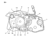
With reference to FIGS. 15 to 17, the developing cartridge 60 of the second embodiment will be described. In the developing cartridge 60, the same members as those in the developing cartridge 10 are denoted by the same reference numerals and description thereof is omitted.

1.現像カートリッジ60の構成
現像カートリッジ60は、図15に示すように、第2ギア62と噛み合う第1ギア61を備える。第1ギア61は、所定の方向において、図16に示す第1位置から、図17に示す第2位置まで移動可能である。第1ギア61が第1位置に位置する場合、第1ギア61は、第2ギア62と噛み合う。第1ギア61が第2位置に位置する場合、第1ギア61と第2ギア62との噛み合いが解除される。
1. Configuration of Developing Cartridge 60 The developing cartridge 60 includes a first gear 61 that meshes with the second gear 62, as shown in FIG. The first gear 61 is movable in a predetermined direction from the first position shown in FIG. 16 to the second position shown in FIG. When the first gear 61 is located at the first position, the first gear 61 meshes with the second gear 62. When the first gear 61 is located at the second position, the meshing between the first gear 61 and the second gear 62 is released.

詳しくは、第1ギア61は、所定の方向において、一端部と、他端部とを有する。他端部は、所定の方向において、一端部に対して筐体2の反対側に位置する。第1ギア61は、第1穴64Aと、第2穴64Bとを有する。第1穴64Aは、所定の方向において、第1ギア61の一端部から第1ギア61の他端部へ向かって凹む。第2穴64Bは、所定の方向において、第1ギア61の他端部から第1ギア61の一端部へ向かって凹む。第1穴64Aと第2穴64Bとは、連通してもよい。   Specifically, the first gear 61 has one end and the other end in a predetermined direction. The other end is located on the opposite side of the housing 2 with respect to the one end in a predetermined direction. The first gear 61 has a first hole 64A and a second hole 64B. First hole 64A is recessed from one end of first gear 61 toward the other end of first gear 61 in a predetermined direction. The second hole 64B is recessed from the other end of the first gear 61 toward one end of the first gear 61 in a predetermined direction. The first hole 64A and the second hole 64B may communicate with each other.

第1穴64Aには、アジテータシャフト4Aの他端部が挿入される。これにより、第1ギア61は、アジテータシャフト4Aの他端部に取り付けられる。アジテータシャフト4Aの他端部の周面は、D形状を有する。詳しくは、アジテータシャフト4Aの他端部の周面は、一部が平面S1(図15参照)であり、残りの部分が円弧面S2(図15参照)である。また、第1穴64Aは、アジテータシャフト4Aの他端部の形状にフィットする形状を有する。これにより、アジテータシャフト4Aの他端部が第1穴64Aに挿入された状態で、第1ギア61は、アジテータシャフト4Aとともに回転可能である。また、第1ギア61は、アジテータシャフト4Aに対して、所定の方向に移動可能である。   The other end of the agitator shaft 4A is inserted into the first hole 64A. Thereby, the first gear 61 is attached to the other end of the agitator shaft 4A. The peripheral surface of the other end of the agitator shaft 4A has a D shape. Specifically, a part of the peripheral surface of the other end of the agitator shaft 4A is a plane S1 (see FIG. 15), and the remaining part is a circular arc surface S2 (see FIG. 15). The first hole 64A has a shape that fits the shape of the other end of the agitator shaft 4A. Accordingly, the first gear 61 can rotate together with the agitator shaft 4A in a state where the other end portion of the agitator shaft 4A is inserted into the first hole 64A. Further, the first gear 61 is movable in a predetermined direction with respect to the agitator shaft 4A.

第2穴64Bには、ギアカバー17に設けられるシャフト65が挿入される。シャフト65は、所定の方向において、アジテータシャフト4Aに対して、筐体2の反対側に位置する。シャフト65は、所定の方向において、アジテータシャフト4Aから離れている。シャフト65は、ギアカバー17と一体的に構成される。詳しくは、シャフト65は、所定の方向において、ギアカバー17の内面からアジテータシャフト4Aに向かって延びる。シャフト65は、ギアカバー17に連続する一端部と、一端部よりもアジテータシャフト4Aに近い他端部とを有する。シャフト65は、突起65Aを備える。突起65Aは、シャフト65の他端部に位置する。突起65Aは、シャフト65の周面から突出する。突起65Aは、シャフト65の径方向に延びる。第1ギア61は、さらに、溝61Bを有する。溝61Bは、第2穴64Bの内面に位置する。溝61Bは、所定の方向に延びる螺旋形状を有する。溝61Bは、所定の方向において、一端部と、他端部とを有する。他端部は、所定の方向において、一端部に対して筐体2の反対側に位置する。第1ギア61が第1位置に位置する場合に、溝61Bの一端部には、シャフト65の突起65Aが嵌まる。螺旋形状の溝61Bに突起65Aが嵌まることにより、第1ギア61は、回転したときに、所定の方向に移動可能である。具体的には、第1ギア61は、回転したときに、筐体2に近づく方向へ移動可能である。なお、第1ギア61の回転方向が、第3の実施形態の第1ギア61の回転方向の逆方向になると、溝61Bの螺旋方向も逆方向となる。これにより、第1ギア61は、回転したときに、筐体2に近づく方向へ移動可能である。   A shaft 65 provided on the gear cover 17 is inserted into the second hole 64B. The shaft 65 is located on the opposite side of the housing 2 with respect to the agitator shaft 4A in a predetermined direction. The shaft 65 is separated from the agitator shaft 4A in a predetermined direction. The shaft 65 is configured integrally with the gear cover 17. Specifically, the shaft 65 extends from the inner surface of the gear cover 17 toward the agitator shaft 4A in a predetermined direction. The shaft 65 has one end continuous to the gear cover 17 and the other end closer to the agitator shaft 4A than the one end. The shaft 65 includes a protrusion 65A. The protrusion 65A is located at the other end of the shaft 65. The protrusion 65A protrudes from the peripheral surface of the shaft 65. The protrusion 65 </ b> A extends in the radial direction of the shaft 65. The first gear 61 further has a groove 61B. The groove 61B is located on the inner surface of the second hole 64B. The groove 61B has a spiral shape extending in a predetermined direction. The groove 61B has one end and the other end in a predetermined direction. The other end is located on the opposite side of the housing 2 with respect to the one end in a predetermined direction. When the first gear 61 is located at the first position, the protrusion 65A of the shaft 65 is fitted to one end of the groove 61B. When the projection 65A is fitted in the spiral groove 61B, the first gear 61 can move in a predetermined direction when it rotates. Specifically, the first gear 61 is movable in a direction approaching the housing 2 when rotated. Note that when the rotation direction of the first gear 61 is opposite to the rotation direction of the first gear 61 of the third embodiment, the spiral direction of the groove 61B is also opposite. Thereby, the 1st gear 61 is movable to the direction approaching the housing | casing 2, when rotating.

さらに、第1ギア61は、複数のギア歯61Cを有する。複数のギア歯61Cは、第1ギア61の周面に位置する。複数のギア歯61Cは、第1ギア61の回転方向に並ぶ。複数のギア歯61Cは、第2ギア62のギア歯に噛み合う。つまり、第1ギア61は、第2ギア62と噛み合う。これにより、第2ギア62は、第1ギア61から駆動力を受けて、突起63とともに回転可能である。   Further, the first gear 61 has a plurality of gear teeth 61C. The plurality of gear teeth 61 </ b> C are located on the peripheral surface of the first gear 61. The plurality of gear teeth 61 </ b> C are arranged in the rotation direction of the first gear 61. The plurality of gear teeth 61 </ b> C mesh with the gear teeth of the second gear 62. That is, the first gear 61 meshes with the second gear 62. As a result, the second gear 62 receives the driving force from the first gear 61 and can rotate together with the protrusion 63.

2.現像カートリッジ60の動作
現像カートリッジ60が画像形成装置に装着されたときには、第1実施形態と同様に、アクチュエータ31(図7A参照)がシャフト23に接触する。また、第1ギア61は、図16に示すように、第1位置に位置する。
2. Operation of Developing Cartridge 60 When the developing cartridge 60 is attached to the image forming apparatus, the actuator 31 (see FIG. 7A) contacts the shaft 23 as in the first embodiment. Further, the first gear 61 is located at the first position as shown in FIG.

そして、画像形成装置からカップリング11(図3参照)に駆動力が入力されると、駆動力は、カップリング11から図示しないギア列およびアジテータシャフト4Aを介して、第1ギア61に伝わる。これにより、第1ギア61が回転する。すると、第1ギア61から駆動力を受けて、第2ギア62が回転する。また、突起63が、第2ギア62とともに回転し、シャフト23の周面に沿って移動する。   When a driving force is input from the image forming apparatus to the coupling 11 (see FIG. 3), the driving force is transmitted from the coupling 11 to the first gear 61 via the gear train (not shown) and the agitator shaft 4A. Thereby, the 1st gear 61 rotates. Then, receiving the driving force from the first gear 61, the second gear 62 rotates. Further, the protrusion 63 rotates together with the second gear 62 and moves along the peripheral surface of the shaft 23.

ここで、第1ギア61は、溝61Bの一端部に突起65Aが嵌まっていることにより、回転するにつれて、筐体2に近づく方向へ移動する。一方、第2ギア62は、所定の方向に移動しないで、回転する。これにより、所定の方向における第1ギア61の移動に伴って、第1ギア61と第2ギア62との噛み合いが解除される。第1ギア61と第2ギア62との噛み合いが解除されることにより、第2ギア62が停止する。第2ギア62が停止することにより、突起63も停止する。なお、第1ギア61と第2ギア62との噛み合いが解除されるタイミングは、突起63が、開口24を1回通過した後、さらに、少なくとも1回、開口24を通過するように、調整される。   Here, the first gear 61 moves in a direction approaching the housing 2 as it rotates because the protrusion 65A is fitted to one end of the groove 61B. On the other hand, the second gear 62 rotates without moving in a predetermined direction. Thus, the meshing of the first gear 61 and the second gear 62 is released with the movement of the first gear 61 in a predetermined direction. When the meshing between the first gear 61 and the second gear 62 is released, the second gear 62 stops. When the second gear 62 stops, the protrusion 63 also stops. The timing at which the meshing between the first gear 61 and the second gear 62 is released is adjusted so that the protrusion 63 passes through the opening 24 at least once after passing through the opening 24 once. The

そして、図17に示すように、シャフト65の突起65Aが溝61Bの他端部に嵌まる位置まで、第1ギア61が移動すると、第1ギア61は、所定の方向への移動を停止する。このときの第1ギア61の位置が、第2位置である。なお、第2実施形態では、第1ギア61は、第2位置において、アジテータシャフト4Aとともに回転し続ける。   As shown in FIG. 17, when the first gear 61 moves to a position where the projection 65A of the shaft 65 fits into the other end of the groove 61B, the first gear 61 stops moving in a predetermined direction. . The position of the first gear 61 at this time is the second position. In the second embodiment, the first gear 61 continues to rotate with the agitator shaft 4A in the second position.

第3実施形態においても、第1実施形態と同様の効果を得ることができる。   Also in the third embodiment, the same effect as in the first embodiment can be obtained.

3.変形例
図18および図19に示すように、第1ギア61は、回転したときに、筐体2から離れる方向へ移動して、第2ギア62との噛み合いを解除してもよい。詳しくは、この変形例の溝61Bは、図16に示す溝61Bとは逆の螺旋形状を有する。これにより、第1ギア61は、回転したときに、筐体2から離れる方向へ移動する。なお、第1ギア61の回転方向が、変形例の第1ギア61の回転方向の逆方向になると、溝61Bの螺旋方向も、変形例の螺旋方向と逆方向となる。これにより、第1ギア61は、回転したときに、筐体2から離れる方向へ移動可能である。
[第4実施形態]
図20から図23を参照して、第4実施形態の現像カートリッジ70について説明する。なお、現像カートリッジ70において、現像カートリッジ10と同じ部材には、同じ符号を付し、説明を省略する。
3. Modifications As shown in FIGS. 18 and 19, the first gear 61 may move in a direction away from the housing 2 to release the mesh with the second gear 62 when rotated. Specifically, the groove 61B of this modification has a spiral shape opposite to that of the groove 61B shown in FIG. Thereby, the first gear 61 moves in a direction away from the housing 2 when rotated. When the rotation direction of the first gear 61 is opposite to the rotation direction of the first gear 61 of the modification, the spiral direction of the groove 61B is also opposite to the spiral direction of the modification. Thereby, the first gear 61 is movable in a direction away from the housing 2 when rotated.
[Fourth Embodiment]
A developing cartridge 70 according to the fourth embodiment will be described with reference to FIGS. In the developing cartridge 70, the same members as those in the developing cartridge 10 are denoted by the same reference numerals, and description thereof is omitted.

1.現像カートリッジ70の構成
現像カートリッジ70は、図20に示すように、第2ギア62と噛み合う第1ギア71と、第1ギア71とアジテータシャフト4Aとを接続する接続部材72とを備える。第1ギア61は、所定の方向と交差する方向において、接続部材72とともに回転可能な第1位置(図21参照)から、接続部材72との接続が解除される第2位置(図23参照)まで移動可能である。第1ギア71が第1位置に位置する場合、第1ギア71は、第2ギア62と噛み合う。第1ギア71が第2位置に位置する場合、第1ギア71と第2ギア62との噛み合いが解除される。
1. As shown in FIG. 20, the developer cartridge 70 includes a first gear 71 that meshes with the second gear 62, and a connection member 72 that connects the first gear 71 and the agitator shaft 4A. The first gear 61 is a second position (see FIG. 23) where the connection with the connection member 72 is released from the first position (see FIG. 21) that can rotate together with the connection member 72 in a direction that intersects the predetermined direction. Can move up to. When the first gear 71 is located at the first position, the first gear 71 meshes with the second gear 62. When the first gear 71 is located at the second position, the meshing between the first gear 71 and the second gear 62 is released.

詳しくは、図20および図21に示すように、接続部材72は、所定の方向において、第1ギア71とアジテータシャフト4Aとの間に位置する。接続部材72は、所定の方向において、一端部と、他端部とを備える。他端部は、所定の方向において、一端部よりも筐体2から離れている。接続部材72の一端部は、アジテータシャフト4Aの他端部に取り付けられる。接続部材72は、アジテータシャフト4Aとともに回転可能である。接続部材72の他端部は、溝72Aを有する。溝72Aは、接続部材72の径方向に延びる。接続部材72の径方向において、溝72Aの両方の端部は、それぞれ、開放されている。   Specifically, as shown in FIGS. 20 and 21, the connection member 72 is positioned between the first gear 71 and the agitator shaft 4 </ b> A in a predetermined direction. The connection member 72 includes one end and the other end in a predetermined direction. The other end is farther from the housing 2 than the one end in a predetermined direction. One end of the connection member 72 is attached to the other end of the agitator shaft 4A. The connecting member 72 can rotate together with the agitator shaft 4A. The other end of the connection member 72 has a groove 72A. The groove 72 </ b> A extends in the radial direction of the connection member 72. In the radial direction of the connecting member 72, both ends of the groove 72A are open.

第1ギア71は、複数のギア歯71Cと、係合部71Aと、溝71Bとを備える。複数のギア歯71Cは、第1ギア71の周面に位置する。複数のギア歯71Cは、第1ギア71の回転方向に沿って並ぶ。係合部71Aは、所定の方向において、複数のギア歯71Cよりも接続部材72の近くに位置する。係合部71Aは、所定の方向において、接続部材72に向かって突出する。係合部71Aは、第1ギア71の径方向に延びる。係合部71Aは、接続部材72の溝72Aに嵌まる。これにより、第1ギア71は、係合部71Aが溝72Aに嵌まった状態で、接続部材72とともに回転可能である。また、第1ギア71は、溝72Aの両方の端部がそれぞれ開放されていることにより、接続部材72に対して、溝72Aが延びる方向にスライド可能である。溝71Bは、所定の方向において、複数のギア歯71Cに対して、係合部71Aの反対側に位置する。溝71Bは、第1ギア71の径方向において、係合部71Aが延びる方向に延びる。第1ギア71の径方向において、溝71Bの端部は、開放されている。溝71Bには、ギアカバー17に設けられるシャフト74が挿入される。シャフト74は、ギアカバー17と一体的に構成されている。詳しくは、シャフト74は、ギアカバー17の内面から延びる。そして、第1ギア71は、ばね73により、第2ギア62から離れる方向へ押圧されている。第1ギア71は、ばね73が第1ギア71を押圧する方向と、溝71Bが延びる方向とが交差する場合(図21参照)には、溝71Bにシャフト74が嵌まっていることにより、ばね73の押圧力に抗して、第1位置に位置する。また、第1ギア71は、ばね73が第1ギア71を押圧する方向と、溝71Bが延びる方向とが一致した場合(図23参照)には、ばね73の押圧力により、第1位置から第2位置へ移動可能となる。   The first gear 71 includes a plurality of gear teeth 71C, an engaging portion 71A, and a groove 71B. The plurality of gear teeth 71 </ b> C are located on the peripheral surface of the first gear 71. The plurality of gear teeth 71 </ b> C are arranged along the rotation direction of the first gear 71. The engaging portion 71A is located closer to the connecting member 72 than the plurality of gear teeth 71C in a predetermined direction. The engaging portion 71A protrudes toward the connecting member 72 in a predetermined direction. The engaging portion 71 </ b> A extends in the radial direction of the first gear 71. The engaging portion 71 </ b> A is fitted into the groove 72 </ b> A of the connecting member 72. Accordingly, the first gear 71 can rotate together with the connection member 72 in a state where the engaging portion 71A is fitted in the groove 72A. Further, the first gear 71 is slidable in the direction in which the groove 72 </ b> A extends with respect to the connection member 72 by opening both ends of the groove 72 </ b> A. The groove 71B is located on the opposite side of the engaging portion 71A with respect to the plurality of gear teeth 71C in a predetermined direction. The groove 71B extends in the radial direction of the first gear 71 in the direction in which the engaging portion 71A extends. In the radial direction of the first gear 71, the end of the groove 71B is open. A shaft 74 provided on the gear cover 17 is inserted into the groove 71B. The shaft 74 is configured integrally with the gear cover 17. Specifically, the shaft 74 extends from the inner surface of the gear cover 17. The first gear 71 is pressed in a direction away from the second gear 62 by the spring 73. When the direction in which the spring 73 presses the first gear 71 and the direction in which the groove 71B extends intersect the first gear 71 (see FIG. 21), the shaft 74 is fitted in the groove 71B. It is located at the first position against the pressing force of the spring 73. Further, when the direction in which the spring 73 presses the first gear 71 coincides with the direction in which the groove 71B extends (see FIG. 23), the first gear 71 is moved from the first position by the pressing force of the spring 73. It can be moved to the second position.

2.現像カートリッジ70の動作
現像カートリッジ70が画像形成装置に装着されたときには、第1実施形態と同様に、アクチュエータ31(図7A参照)がシャフト23に接触する。また、第1ギア71は、図21に示すように、第1位置に位置する。
2. Operation of Developing Cartridge 70 When the developing cartridge 70 is mounted on the image forming apparatus, the actuator 31 (see FIG. 7A) contacts the shaft 23 as in the first embodiment. The first gear 71 is located at the first position as shown in FIG.

そして、画像形成装置からカップリング11(図3参照)に駆動力が入力されると、駆動力は、カップリング11から図示しないギア列およびアジテータシャフト4Aを介して、接続部材72に伝わる。これにより、第1ギア71が、接続部材72とともに回転する。すると、第1ギア71から駆動力を受けて、第2ギア62が回転する。また、突起63が、第2ギア62とともに回転し、シャフト23の周面に沿って移動する。   When a driving force is input from the image forming apparatus to the coupling 11 (see FIG. 3), the driving force is transmitted from the coupling 11 to the connecting member 72 via a gear train (not shown) and the agitator shaft 4A. As a result, the first gear 71 rotates together with the connection member 72. Then, receiving the driving force from the first gear 71, the second gear 62 rotates. Further, the protrusion 63 rotates together with the second gear 62 and moves along the peripheral surface of the shaft 23.

そして、図22に示すように、第1ギア71が回転するにつれて、溝71Bが回転し、溝71Bが延びる方向と、ばね73が第1ギア71を押圧する方向とが一致すると、図23に示すように、ばね73の押圧力により、第1ギア71が、第1位置から第2位置へ移動する。   Then, as shown in FIG. 22, as the first gear 71 rotates, the groove 71 </ b> B rotates and the direction in which the groove 71 </ b> B extends coincides with the direction in which the spring 73 presses the first gear 71. As shown, the first gear 71 is moved from the first position to the second position by the pressing force of the spring 73.

すると、第1ギア71が第2ギア62から離間し、第1ギア71と第2ギア62との噛み合いが解除される。第1ギア71と第2ギア62との噛み合いが解除されることにより、第2ギア62が停止する。第2ギア62が停止することにより、突起63も停止する。なお、第1ギア71と第2ギア62との噛み合いが解除されるタイミングは、突起63が、開口24を1回通過した後、さらに、少なくとも1回、開口24を通過するように、調整される。   Then, the first gear 71 is separated from the second gear 62 and the meshing between the first gear 71 and the second gear 62 is released. When the meshing between the first gear 71 and the second gear 62 is released, the second gear 62 stops. When the second gear 62 stops, the protrusion 63 also stops. The timing at which the meshing between the first gear 71 and the second gear 62 is released is adjusted so that the protrusion 63 passes through the opening 24 at least once after passing through the opening 24 once. The

なお、第1ギア71が第2位置に位置した後、第1ギア71は、ばね73の押圧力により、第1位置への移動を止められる。すなわち、ばね73は、第1ギア71を第2位置に位置させた後、第1ギア71を第2位置に固定するストッパとして機能する。   Note that after the first gear 71 is positioned at the second position, the first gear 71 is stopped from moving to the first position by the pressing force of the spring 73. That is, the spring 73 functions as a stopper that fixes the first gear 71 to the second position after the first gear 71 is positioned to the second position.

第4実施形態においても、第1実施形態と同様の効果を得ることができる。
[第5実施形態]
図24を参照して、第5実施形態の現像カートリッジ80について説明する。なお、現像カートリッジ80において、現像カートリッジ40と同じ部材には、同じ符号を付し、説明を省略する。
Also in the fourth embodiment, the same effect as in the first embodiment can be obtained.
[Fifth Embodiment]
A developing cartridge 80 according to the fifth embodiment will be described with reference to FIG. In the developing cartridge 80, the same members as those in the developing cartridge 40 are denoted by the same reference numerals, and description thereof is omitted.

上記した第1実施形態から第4実施形態では、突起が、画像形成装置のアクチュエータを移動させているが、例えば、突起45が接触することによりピボットするピボット部材81により、アクチュエータを移動させることもできる。   In the first to fourth embodiments described above, the protrusion moves the actuator of the image forming apparatus. For example, the actuator may be moved by the pivot member 81 that pivots when the protrusion 45 contacts. it can.

ピボット部材81は、所定の方向に延びる第3軸A3についてピボット可能である。詳しくは、ピボット部材81は、第1接触部82と、第2接触部83とを備える。第1接触部82には、突起45が接触する。第2接触部83は、第1接触部82に対して第3軸A3の反対側に位置する。第2接触部83は、アクチュエータに接触可能である。   The pivot member 81 can pivot about a third axis A3 extending in a predetermined direction. Specifically, the pivot member 81 includes a first contact portion 82 and a second contact portion 83. The protrusion 45 is in contact with the first contact portion 82. The second contact portion 83 is located on the opposite side of the third axis A3 with respect to the first contact portion 82. The second contact portion 83 can contact the actuator.

そして、第1ギア43が第1位置から第2位置まで移動する間、2つの突起45のそれぞれは、ピボット部材81に、1回接触した後、さらに、少なくとも1回、接触する。これにより、第2ギア44が回転している間に、ピボット部材81は、4回、ピボットする。   Then, while the first gear 43 moves from the first position to the second position, each of the two protrusions 45 contacts the pivot member 81 once and then contacts at least once. As a result, the pivot member 81 pivots four times while the second gear 44 is rotating.

1 現像カートリッジ
6 第1ギア
7 アイドルギア
8 第2ギア
9 突起
10 現像カートリッジ
13 アイドルギア
14 第1ギア
15 第2ギア
16 突起
17 ギアカバー
24 開口
40 現像カートリッジ
42 アイドルギア
43 第1ギア
44 第2ギア
45 突起
60 現像カートリッジ
61 第1ギア
62 第2ギア
63 突起
70 現像カートリッジ
71 第1ギア
73 ばね
80 現像カートリッジ
81 ピボット部材
A1 第1軸
A2 第2軸
A3 第3軸
DESCRIPTION OF SYMBOLS 1 Developing cartridge 6 1st gear 7 Idle gear 8 2nd gear 9 Protrusion 10 Developing cartridge 13 Idle gear 14 1st gear 15 2nd gear 16 Protrusion 17 Gear cover 24 Opening 40 Developing cartridge 42 Idle gear 43 1st gear 44 2nd Gear 45 Protrusion 60 Developer cartridge 61 First gear 62 Second gear 63 Protrusion 70 Developer cartridge 71 First gear 73 Spring 80 Developer cartridge 81 Pivot member A1 First shaft A2 Second shaft A3 Third shaft

Claims (12)

所定の方向に延びる第1軸について回転可能な第1ギアであって、第1位置から第2位置まで移動可能な第1ギアと、
前記第1ギアから駆動力を受けて、前記所定の方向に延びる第2軸について回転可能な第2ギアと、
開口を有するギアカバーであって、前記第2ギアの少なくとも一部を覆うギアカバーと、
前記所定の方向に延びる突起であって、前記第2ギアとともに回転可能な突起であり、前記第1ギアが前記第1位置から前記第2位置まで移動する間、前記第2ギアとともに回転可能な突起であり、前記第2ギアとともに回転している間に、前記開口を1回通過した後、さらに、少なくとも1回、前記開口を通過する突起と、
を備えることを特徴とする現像カートリッジ。
A first gear rotatable about a first axis extending in a predetermined direction, the first gear movable from a first position to a second position;
A second gear that receives a driving force from the first gear and is rotatable about a second shaft extending in the predetermined direction;
A gear cover having an opening, the gear cover covering at least a part of the second gear;
A protrusion extending in the predetermined direction and rotatable with the second gear, and rotatable with the second gear while the first gear moves from the first position to the second position. A protrusion that passes through the opening once and then passes through the opening at least once while rotating with the second gear;
A developing cartridge comprising:
前記現像カートリッジは、前記第1ギアと噛み合うアイドルギアを、さらに備え、
前記第1ギアと前記アイドルギアとの噛み合いが解除されることにより、前記第2ギアが停止することを特徴とする請求項1に記載の現像カートリッジ。
The developer cartridge further includes an idle gear that meshes with the first gear,
The developing cartridge according to claim 1, wherein the second gear is stopped by releasing the meshing between the first gear and the idle gear.
前記第1ギアは、前記第2ギアと噛み合い、
前記第1ギアと前記第2ギアとの噛み合いが解除されることにより、前記第2ギアが停止することを特徴とする請求項1に記載の現像カートリッジ。
The first gear meshes with the second gear;
The developing cartridge according to claim 1, wherein the second gear is stopped by releasing the meshing between the first gear and the second gear.
前記第1ギアは、前記第1ギアの周囲の一部に、複数のギア歯を有することを特徴とする請求項1から請求項3のいずれか一項に記載の現像カートリッジ。   4. The developing cartridge according to claim 1, wherein the first gear has a plurality of gear teeth on a part of the periphery of the first gear. 5. 前記第1ギアは、欠け歯部分を有することを特徴とする、請求項4に記載の現像カートリッジ。   The developing cartridge according to claim 4, wherein the first gear has a missing tooth portion. 前記現像カートリッジは、前記第1ギアと噛み合うアイドルギアを、さらに備え、
前記第1ギアが前記第2位置のときに、前記第1ギアは、前記アイドルギアの複数のギア歯のいずれのギア歯とも噛み合わないことを特徴とする、請求項4または請求項5に記載の現像カートリッジ。
The developer cartridge further includes an idle gear that meshes with the first gear,
The said 1st gear does not mesh with any gear tooth of the several gear teeth of the said idle gear when the said 1st gear is in the said 2nd position, The Claim 4 or Claim 5 characterized by the above-mentioned. Development cartridge.
前記第2ギアは、前記第2ギアの周囲に複数のギア歯を有し、
前記第1ギアが有する複数のギア歯の歯数は、前記第2ギアが有する複数のギア歯の歯数の1.5倍以上であることを特徴とする請求項4から請求項6のいずれか一項に記載の現像カートリッジ。
The second gear has a plurality of gear teeth around the second gear;
The number of teeth of the plurality of gear teeth included in the first gear is 1.5 times or more of the number of teeth of the plurality of gear teeth included in the second gear. The developing cartridge according to claim 1.
前記第1ギアの歯先円の径は、前記第2ギアの歯先円の径の1.5倍以上であることを特徴とする請求項1から請求項7のいずれか一項に記載の現像カートリッジ。   8. The diameter of the tip circle of the first gear is 1.5 times or more of the diameter of the tip circle of the second gear. 8. Developer cartridge. 前記第1ギアは、前記所定の方向において、前記第1位置から前記第2位置まで移動可能であることを特徴とする請求項1から請求項3のいずれか一項に記載の現像カートリッジ。   4. The developing cartridge according to claim 1, wherein the first gear is movable from the first position to the second position in the predetermined direction. 5. 前記現像カートリッジは、前記第1ギアを前記第2位置に固定するストッパを、さらに備えることを特徴とする請求項1から請求項9のいずれか一項に記載の現像カートリッジ。   10. The developing cartridge according to claim 1, further comprising a stopper that fixes the first gear to the second position. 11. 前記現像カートリッジは、現像剤を収容可能なカートリッジであることを特徴とする請求項1から請求項10のいずれか一項に記載の現像カートリッジ。   The developing cartridge according to any one of claims 1 to 10, wherein the developing cartridge is a cartridge capable of containing a developer. 所定の方向に延びる第1軸について回転可能な第1ギアであって、第1位置から第2位置まで移動可能な第1ギアと、
前記第1ギアから駆動力を受けて、前記所定の方向に延びる第2軸について回転可能な第2ギアと、
前記所定の方向に延びる突起であって、前記第2ギアとともに回転可能な突起であり、前記第1ギアが前記第1位置から前記第2位置まで移動する間、前記第2ギアとともに回転可能な突起と、
所定の方向に延びる第3軸についてピボット可能なピボット部材であって、前記突起が接触することによりピボットするピボット部材と、
を備え、
前記第1ギアが前記第1位置から前記第2位置まで移動する間、前記突起は、前記ピボット部材に、1回接触した後、さらに、少なくとも1回、接触することを特徴とする現像カートリッジ。
A first gear rotatable about a first axis extending in a predetermined direction, the first gear movable from a first position to a second position;
A second gear that receives a driving force from the first gear and is rotatable about a second shaft extending in the predetermined direction;
A protrusion extending in the predetermined direction and rotatable with the second gear, and rotatable with the second gear while the first gear moves from the first position to the second position. Protrusions,
A pivot member pivotable about a third axis extending in a predetermined direction, wherein the pivot member pivots by contact of the protrusion;
With
The developing cartridge is characterized in that, while the first gear moves from the first position to the second position, the protrusion contacts the pivot member once and then contacts at least once.
JP2016060606A 2016-03-24 2016-03-24 Developing cartridge Pending JP2017173619A (en)

Priority Applications (4)

Application Number Priority Date Filing Date Title
JP2016060606A JP2017173619A (en) 2016-03-24 2016-03-24 Developing cartridge
US15/275,698 US9964917B2 (en) 2016-03-24 2016-09-26 Developing cartridge provided with protrusion movable with rotation of gear
PCT/JP2016/078175 WO2017163465A1 (en) 2016-03-24 2016-09-26 Development cartridge
CN201680083886.8A CN109074015B (en) 2016-03-24 2016-09-26 Developing box

Applications Claiming Priority (1)

Application Number Priority Date Filing Date Title
JP2016060606A JP2017173619A (en) 2016-03-24 2016-03-24 Developing cartridge

Publications (1)

Publication Number Publication Date
JP2017173619A true JP2017173619A (en) 2017-09-28

Family

ID=59897150

Family Applications (1)

Application Number Title Priority Date Filing Date
JP2016060606A Pending JP2017173619A (en) 2016-03-24 2016-03-24 Developing cartridge

Country Status (4)

Country Link
US (1) US9964917B2 (en)
JP (1) JP2017173619A (en)
CN (1) CN109074015B (en)
WO (1) WO2017163465A1 (en)

Cited By (2)

* Cited by examiner, † Cited by third party
Publication number Priority date Publication date Assignee Title
WO2019064643A1 (en) * 2017-09-29 2019-04-04 ブラザー工業株式会社 Developer cartridge
WO2019064642A1 (en) * 2017-09-29 2019-04-04 ブラザー工業株式会社 Developer cartridge

Families Citing this family (2)

* Cited by examiner, † Cited by third party
Publication number Priority date Publication date Assignee Title
CN109514543A (en) * 2018-12-24 2019-03-26 深圳市优必选科技有限公司 A kind of steering engine and robot
JP2022157182A (en) 2021-03-31 2022-10-14 ブラザー工業株式会社 Developing cartridge

Family Cites Families (15)

* Cited by examiner, † Cited by third party
Publication number Priority date Publication date Assignee Title
JP4348632B2 (en) 2005-02-28 2009-10-21 ブラザー工業株式会社 Image forming apparatus and developing cartridge
CN200962188Y (en) * 2005-02-28 2007-10-17 兄弟工业株式会社 Developer box
JP2007093753A (en) * 2005-09-27 2007-04-12 Brother Ind Ltd Developing cartridge, process cartridge and image forming apparatus
JP4857739B2 (en) * 2005-11-30 2012-01-18 ブラザー工業株式会社 Image forming apparatus and developing cartridge
JP4919124B2 (en) * 2010-03-31 2012-04-18 ブラザー工業株式会社 cartridge
JP5115607B2 (en) * 2010-08-31 2013-01-09 ブラザー工業株式会社 Caps and cartridges
JP5884343B2 (en) 2011-08-31 2016-03-15 ブラザー工業株式会社 Process cartridge and developer cartridge
JP5348209B2 (en) * 2011-08-31 2013-11-20 ブラザー工業株式会社 cartridge
JP5182402B2 (en) * 2011-08-31 2013-04-17 ブラザー工業株式会社 cartridge
CN202975598U (en) 2011-12-07 2013-06-05 珠海赛纳打印科技股份有限公司 Powder box for electro-photographic imaging device
JP2014191161A (en) * 2013-03-27 2014-10-06 Brother Ind Ltd Image forming apparatus
JP6137027B2 (en) 2014-03-31 2017-05-31 ブラザー工業株式会社 cartridge
JP6135583B2 (en) 2014-03-31 2017-05-31 ブラザー工業株式会社 cartridge
CN204903950U (en) * 2015-08-27 2015-12-23 珠海艾派克科技股份有限公司 Developing box
CN205003445U (en) * 2015-09-23 2016-01-27 珠海艾派克科技股份有限公司 Developing box

Cited By (4)

* Cited by examiner, † Cited by third party
Publication number Priority date Publication date Assignee Title
WO2019064643A1 (en) * 2017-09-29 2019-04-04 ブラザー工業株式会社 Developer cartridge
WO2019064642A1 (en) * 2017-09-29 2019-04-04 ブラザー工業株式会社 Developer cartridge
JP2019066576A (en) * 2017-09-29 2019-04-25 ブラザー工業株式会社 Developer cartridge
JP2019066577A (en) * 2017-09-29 2019-04-25 ブラザー工業株式会社 Developer cartridge

Also Published As

Publication number Publication date
CN109074015A (en) 2018-12-21
WO2017163465A1 (en) 2017-09-28
US9964917B2 (en) 2018-05-08
CN109074015B (en) 2021-11-30
US20170277116A1 (en) 2017-09-28

Similar Documents

Publication Publication Date Title
WO2017163465A1 (en) Development cartridge
JP2018005174A (en) Developing cartridge
US10983456B2 (en) Developer cartridge provided with gear having engagement portions
WO2017170511A1 (en) Toner cartridge
WO2018061257A1 (en) Development cartridge
WO2017163466A1 (en) Development cartridge
WO2017168858A1 (en) Development cartridge
WO2017154299A1 (en) Developer cartridge
JP6387844B2 (en) Developer cartridge
JP6917013B2 (en) Developer cartridge
CN110874036B (en) Developing box
US9946220B2 (en) Developer cartridge having gear with protruding part in which movement of protruding part can be delayed
WO2018123168A1 (en) Developer cartridge
WO2017057489A1 (en) Developing cartridge and drum cartridge
CN110187619B (en) Developing box
JP2017151361A (en) Developer cartridge
JP2017182006A (en) Toner cartridge
JP7180725B2 (en) developer cartridge
JP2022155673A (en) toner cartridge
JP6926850B2 (en) Toner cartridge
JP6822139B2 (en) Development cartridge