JP2017172883A - Heat storage panel - Google Patents
Heat storage panel Download PDFInfo
- Publication number
- JP2017172883A JP2017172883A JP2016060030A JP2016060030A JP2017172883A JP 2017172883 A JP2017172883 A JP 2017172883A JP 2016060030 A JP2016060030 A JP 2016060030A JP 2016060030 A JP2016060030 A JP 2016060030A JP 2017172883 A JP2017172883 A JP 2017172883A
- Authority
- JP
- Japan
- Prior art keywords
- heat storage
- panel
- impregnation
- fixing
- latent heat
- Prior art date
- Legal status (The legal status is an assumption and is not a legal conclusion. Google has not performed a legal analysis and makes no representation as to the accuracy of the status listed.)
- Granted
Links
Images


Classifications
-
- Y—GENERAL TAGGING OF NEW TECHNOLOGICAL DEVELOPMENTS; GENERAL TAGGING OF CROSS-SECTIONAL TECHNOLOGIES SPANNING OVER SEVERAL SECTIONS OF THE IPC; TECHNICAL SUBJECTS COVERED BY FORMER USPC CROSS-REFERENCE ART COLLECTIONS [XRACs] AND DIGESTS
- Y02—TECHNOLOGIES OR APPLICATIONS FOR MITIGATION OR ADAPTATION AGAINST CLIMATE CHANGE
- Y02E—REDUCTION OF GREENHOUSE GAS [GHG] EMISSIONS, RELATED TO ENERGY GENERATION, TRANSMISSION OR DISTRIBUTION
- Y02E60/00—Enabling technologies; Technologies with a potential or indirect contribution to GHG emissions mitigation
- Y02E60/14—Thermal energy storage
Abstract
Description
本発明は、潜熱蓄熱材を有した蓄熱パネルに関する。 The present invention relates to a heat storage panel having a latent heat storage material.
近年、環境性の観点から、壁材、床材、天井材などの建材の技術分野において、室内暖房時に発生する熱エネルギや、日射光などの自然エネルギをより有効に活用するような研究・開発が盛んに取り組まれており、これらの研究・開発に基づいた省エネおよびエコ対策が講じられている。 In recent years, research and development to make more effective use of thermal energy generated during indoor heating and natural energy such as solar radiation in the technical field of building materials such as wall materials, floor materials, and ceiling materials from the viewpoint of environmental performance Is actively engaged in, and energy conservation and ecological measures are taken based on these research and development.
このような点を鑑みて、壁材、床材、天井材などに、蓄熱材を用いた蓄熱パネルの開発がなされている。ここで、蓄熱材として、融点(相変化温度)以上の温度で蓄熱することができる潜熱蓄熱材が注目されており、この潜熱蓄熱材を利用した様々な蓄熱パネルが提案されている。 In view of these points, heat storage panels using heat storage materials have been developed for wall materials, floor materials, ceiling materials, and the like. Here, as a heat storage material, a latent heat storage material capable of storing heat at a temperature equal to or higher than the melting point (phase change temperature) has been attracting attention, and various heat storage panels using the latent heat storage material have been proposed.
このような技術として、たとえば、特許文献1には、エチレン−αオレフィン共重合体と結晶性有機化合物(潜熱蓄熱材)との溶融混合物を、多孔質材料に含浸した蓄熱パネルが提案されている。この蓄熱パネルによれば、潜熱蓄熱材が、エチレン−αオレフィン共重合体と共に多孔質材料に含浸されているので、多孔質材料から潜熱蓄熱材が滲み出すことを低減することができる。
As such a technique, for example,
しかしながら、特許文献1に示す蓄熱パネルを用いた場合であっても、潜熱蓄熱材が溶融した際には、蓄熱パネルから潜熱蓄熱材の滲み出しを完全に防止することはできない。したがって、壁面等の設置面に蓄熱パネルを直接固定する前に、蓄熱パネルの全面をシート材で被覆することが多い。
However, even when the heat storage panel shown in
このような対策を講じたとしても、釘などの固定具で、蓄熱パネルを設置面に固定する際には、固定具がシート材と共に蓄熱パネルを貫通する。これにより、固定具により形成された貫通孔から、溶融した潜熱蓄熱材が漏れ出たり揮発したりし、蓄熱パネルの蓄熱性能が低下することが想定される。 Even if such measures are taken, when the heat storage panel is fixed to the installation surface with a fixing tool such as a nail, the fixing tool penetrates the heat storage panel together with the sheet material. Thereby, it is assumed that the molten latent heat storage material leaks out or volatilizes from the through-hole formed by the fixture, and the heat storage performance of the heat storage panel is lowered.
本発明は、このような点を鑑みてなされたものであり、固定具で設置面に固定したとしても、潜熱蓄熱材の漏洩または揮発により蓄熱性能が低下することを防止することができる蓄熱パネルを提供することにある。 This invention is made in view of such a point, and even if it fixes to an installation surface with a fixing tool, the thermal storage panel which can prevent that thermal storage performance falls by the leakage or volatilization of a latent heat storage material. Is to provide.
前記課題を鑑みて、本発明に係る蓄熱パネルは、潜熱蓄熱材を有した蓄熱パネルであって、多孔質基材に前記潜熱蓄熱材が含浸された含浸部と、前記含浸部の周りに形成され、前記蓄熱パネルを設置面に固定するための固定具が貫通する固定部と、を有したパネル材と、前記パネル材の両側から、前記含浸部の表面と、前記含浸部の表面に隣接した固定部の表面と、を少なくとも覆うシート材と、を備え、前記蓄熱パネルは、前記含浸部から前記固定部に向かう前記潜熱蓄熱材を遮断するように構成されていることを特徴とする。 In view of the above problems, the heat storage panel according to the present invention is a heat storage panel having a latent heat storage material, and is formed around an impregnation portion in which a porous base material is impregnated with the latent heat storage material, and the impregnation portion. A fixing member through which a fixing tool for fixing the heat storage panel to the installation surface penetrates, a surface of the impregnation portion, and a surface of the impregnation portion from both sides of the panel material And a sheet material covering at least the surface of the fixed portion, wherein the heat storage panel is configured to block the latent heat storage material from the impregnation portion toward the fixing portion.
本発明によれば、蓄熱パネルの含浸部に潜熱蓄熱材が含浸されているので、蓄熱パネルに入熱される熱を潜熱蓄熱材で蓄熱し、これを放熱することができる。ここで、含浸部から固定部に向かう潜熱蓄熱材は遮断されているので、含浸部で溶融した潜熱蓄熱材が固定部に向かうことはない。したがって、蓄熱パネルの固定部に固定具を貫通させて、蓄熱パネルを設置面に固定したとしても、固定具により固定部に形成された貫通孔から含浸部の潜熱蓄熱材が漏洩または揮発することはない。このような結果、設置面に固定された蓄熱パネルの蓄熱性能の低下を防止することができる。 According to the present invention, since the latent heat storage material is impregnated in the impregnation part of the heat storage panel, the heat input to the heat storage panel can be stored by the latent heat storage material and can be dissipated. Here, since the latent heat storage material heading from the impregnation portion to the fixing portion is blocked, the latent heat storage material melted in the impregnation portion does not go to the fixing portion. Therefore, even if a fixing tool is passed through the fixing part of the heat storage panel and the heat storage panel is fixed to the installation surface, the latent heat storage material of the impregnation part may leak or volatilize from the through hole formed in the fixing part by the fixing tool. There is no. As a result, it is possible to prevent a decrease in the heat storage performance of the heat storage panel fixed to the installation surface.
より好ましい態様としては、前記固定部は、前記多孔質基材に、熱硬化性樹脂が含浸された部分、または前記潜熱蓄熱材の相変化温度よりも高い融点を有する熱可塑性樹脂が含浸された部分である。 As a more preferable aspect, the fixing part is impregnated with a portion of the porous substrate impregnated with a thermosetting resin or a thermoplastic resin having a melting point higher than the phase change temperature of the latent heat storage material. Part.
この態様によれば、固定部に相当する多孔質基材の一部には、熱硬化性樹脂または潜熱蓄熱材の相変化温度よりも高い融点を有する熱可塑性樹脂が含浸されているので、含浸部から固定部に向かう潜熱蓄熱材を遮断することができる。これにより、固定具で蓄熱パネルを設置面に固定したとしても、固定部の貫通孔から含浸部の潜熱蓄熱材が漏洩または揮発することはない。また、固定部は多孔質基材(の縁部)に樹脂が含浸されているので、多孔質基材のみの場合に比べて、その強度を高めることができる。 According to this aspect, a part of the porous base material corresponding to the fixing part is impregnated with the thermoplastic resin having a melting point higher than the phase change temperature of the thermosetting resin or the latent heat storage material. It is possible to block the latent heat storage material from the part toward the fixed part. Thereby, even if the heat storage panel is fixed to the installation surface with a fixing tool, the latent heat storage material in the impregnation portion does not leak or volatilize from the through hole of the fixing portion. In addition, since the fixing portion is impregnated with resin in the porous base material (the edge thereof), the strength can be increased as compared with the case of only the porous base material.
また別の好ましい態様としては、前記固定部は、前記含浸部を保持するように前記含浸部の周縁を囲う枠体であり、前記含浸部と前記固定部との間には、前記含浸部から前記固定部に向かう前記潜熱蓄熱材を遮断する遮断部材が配置されている。 In another preferred embodiment, the fixing portion is a frame body that surrounds the periphery of the impregnation portion so as to hold the impregnation portion, and the impregnation portion is interposed between the impregnation portion and the fixing portion. A blocking member that blocks the latent heat storage material facing the fixed portion is disposed.
この態様によれば、含浸部と固定部との間に配置された遮断部材により、含浸部から固定部に向かう前記潜熱蓄熱材を遮断することができる。この結果、固定部である枠体に固定具を貫通させて、蓄熱パネルを設置面に設置しても、含浸部の潜熱蓄熱材が外部に漏洩または揮発することがない。また、遮断部材により含浸部から固定部へ向かう潜熱蓄熱材を遮断できるので、枠体の素材は限定されない。 According to this aspect, the latent heat storage material directed from the impregnation portion to the fixing portion can be interrupted by the blocking member disposed between the impregnation portion and the fixing portion. As a result, the latent heat storage material in the impregnation part does not leak or volatilize outside even if the fixing tool is passed through the frame that is the fixing part and the heat storage panel is installed on the installation surface. Moreover, since the latent heat storage material which goes to a fixed part from an impregnation part can be interrupted | blocked by the interruption | blocking member, the raw material of a frame is not limited.
さらに別のより好ましい態様としては、前記固定部は、前記含浸部を保持するように前記含浸部の周縁を囲う無孔質の枠体である。この態様によれば、固定部を無孔質の枠体とすることにより、含浸部から固定部に向かう潜熱蓄熱材を遮断することができる。この結果、固定部である枠体に固定具を貫通させて、蓄熱パネルを設置面に設置しても、含浸部の潜熱蓄熱材が外部に漏洩または揮発することがない。パネル材を製造する際には、多孔質基材に潜熱蓄熱材を含浸した含浸パネルを無孔質の枠体に組み付ければよいので、他の態様に比べて、蓄熱パネルを簡単に製造することができる。 As another more preferable aspect, the fixing portion is a nonporous frame body that surrounds the periphery of the impregnation portion so as to hold the impregnation portion. According to this aspect, by making the fixing portion a non-porous frame, it is possible to block the latent heat storage material from the impregnation portion toward the fixing portion. As a result, the latent heat storage material in the impregnation part does not leak or volatilize outside even if the fixing tool is passed through the frame that is the fixing part and the heat storage panel is installed on the installation surface. When manufacturing a panel material, an impregnated panel in which a porous base material is impregnated with a latent heat storage material may be assembled to a non-porous frame, so that a heat storage panel is easily manufactured compared to other embodiments. be able to.
以下に、本発明の第1〜第4実施形態に係る蓄熱パネルを図1〜9を参照しながら説明する。 Below, the thermal storage panel which concerns on 1st-4th embodiment of this invention is demonstrated, referring FIGS.
〔第1実施形態〕
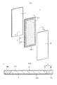
図1(a)は、本発明の第1実施形態に係る蓄熱パネル1の模式的分解斜視図であり、図1(b)は、図1(a)のA−A線矢視断面図である。
[First Embodiment]
Fig.1 (a) is a typical disassembled perspective view of the
1.蓄熱パネル1について
図1(a)および図1(b)に示すように、本実施形態に係る蓄熱パネル1は、床、天井、屋根、内壁、外壁等の建物の部分を構成する建材として単独で又は他の建材と組み合わせて使用することで、この部分に蓄熱性を付与するものである。蓄熱パネル1は、パネル状(ボード状)の形状をしており、図1(a)に示す蓄熱パネル1は、平面視において長方形状であるが、以下に示す構成を備えていれば、平面視において正方形状、円形状、楕円形状、多角形状など、その形状は、特に限定されるものではない。
1. About
図1(a)に示すように、蓄熱パネル1は、パネル材2と、パネル材2を両側から覆う一対のシート材4,4とを備えている。本実施形態では、パネル材2は、多孔質材料に潜熱蓄熱材が含浸された含浸部21と、含浸部21の周りに形成された固定部22とを有している。固定部22は、後述するように、蓄熱パネル1を柱7Aまたは間柱7B等の設置面7aに固定するための、釘、ネジなどの固定具70が貫通する部分である。本実施形態では、後述するように、1枚の板状の多孔質基材から、含浸部21と固定部22が形成されている。
As shown to Fig.1 (a), the
ここで、多孔質基材の厚さは特に限定されないが、通常は3〜30mmであり、好ましくは5〜20mmである。本実施形態では、多孔質基材の含浸部21には、潜熱蓄熱材が含浸されており、固定部22には、含浸部21の周りの多孔質基材の部分には、潜熱蓄熱材は含浸されず、熱硬化させた熱硬化性樹脂、または、潜熱蓄熱材の相変化温度よりも高い融点を有する熱可塑性樹脂が含浸されている。なお、「熱硬化させた熱硬化性樹脂が含浸されている」とは、多孔質基材の部分の空隙に、未硬化の熱硬化性樹脂を含浸させた後、これを熱硬化させた状態のことをいう。含浸部21には、多孔質基材の厚さ方向に亘って潜熱蓄熱材が全体的に含浸されていることが好ましいが、これには限定されず、多孔質基材のうち表層部分のみに潜熱蓄熱材が含浸されてもよい。
Here, although the thickness of a porous base material is not specifically limited, Usually, it is 3-30 mm, Preferably it is 5-20 mm. In this embodiment, the impregnated
多孔質基材は、潜熱蓄熱材を含浸し保持することができる微細な空隙を有する材料からなり、含浸部21の潜熱蓄熱材および固定部22の樹脂を含浸することができるのであれば、その材料は限定されるものではない。
If the porous base material is made of a material having fine voids that can be impregnated and held with the latent heat storage material, and can be impregnated with the latent heat storage material of the
多孔質基材の材料としては、たとえば、パーティクルボード(PB)、木質繊維板(MDF・インシュレーションボード・ハードボードなど)などの木質系ボードを挙げることができる。この他にも、石膏ボード、ケイ酸カルシウム板などの無機質ボード、鉱物質がボード状に成形された鉱物質ボード、グラスウール、カーボンファイバー、または金属繊維等の無機繊維を集積したボードなどを挙げることができる。 Examples of the material for the porous substrate include wood boards such as particle boards (PB) and wood fiber boards (MDF, insulation boards, hard boards, etc.). Other examples include inorganic boards such as gypsum board and calcium silicate board, mineral boards in which mineral substances are formed into a board shape, boards that accumulate inorganic fibers such as glass wool, carbon fiber, or metal fibers. Can do.
含浸部21に含浸されている潜熱蓄熱材は、例えば、室内の暖房、日光による熱等で固相から液相に相変化する潜熱蓄熱材であり、好ましくは相変化温度18℃〜30℃の範囲にある潜熱蓄熱材である。具体的には、硫酸ナトリウム水和物、塩化カルシウム水和物、パラフィン(たとえばC18H38)、ポリエチレングリコール(分子量500〜1000)硫酸ナトリウム10水和塩などを挙げることができ、この相変化温度以上において蓄熱することができるものであれば、その材料は特に限定されるものではない。
The latent heat storage material impregnated in the
また、この他にも、含浸部21に含浸されている潜熱蓄熱材は、相変化温度以上でゲル状となる潜熱蓄熱材であってもよい。相変化温度以上で固形状からゲル状となるので、相変化温度以上になったとしても潜熱蓄熱材の形状を容易に保持することができる。このような潜熱蓄熱材としてはたとえば、三菱電線工業(株)製の潜熱蓄熱材MHSRシリーズなどを挙げることができる。
In addition to this, the latent heat storage material impregnated in the
さらに、例えば、出願人が既に出願した国際公開第2015/174523号に開示されるように、潜熱蓄熱材に所定の水素添加スチレン系熱可塑性エラストマーを含んだ蓄熱材組成物が、パネル材2に含浸されていてもよい。水素添加スチレン系熱可塑性エラストマーとしては、スチレン−エチレン/ブチレン−スチレンブロック共重合体(SEBS)、スチレン−エチレン/プロピレンブロック共重合体(SEP)、スチレン−エチレン/プロピレン−スチレンブロック共重合体(SEPS)、及びスチレン−エチレン−エチレン/プロピレン−スチレンブロック共重合体(SEEPS)からなる群から選択される少なくとも1種(2種以上の混合物であってもよい)等を挙げることができる。
Further, for example, as disclosed in International Publication No. 2015/174523 filed by the applicant, a heat storage material composition containing a predetermined hydrogenated styrene-based thermoplastic elastomer in the latent heat storage material is applied to the
図1(a)および図1(b)に示すように、本実施形態では、固定部22は、パネル材2の厚さ方向に亘って、含浸部21を囲うとともに、含浸部21から固定部22に向かう潜熱蓄熱材を遮断するように構成された部材である。具体的には、本実施形態では、固定部22は、上述した如く、含浸部21を囲うように、多孔質基材の縁部に、熱硬化性樹脂が含浸された部分、または潜熱蓄熱材の相変化温度よりも高い融点を有する熱可塑性樹脂が含浸された部分である。
As shown in FIG. 1A and FIG. 1B, in this embodiment, the fixing
固定部22に含浸される樹脂としては、蓄熱パネル1の使用時に樹脂が軟化しないものであり、120℃以上で軟化しない熱可塑性樹脂または(硬化後の)熱硬化性樹脂であることが好ましい。例えば、このような熱可塑性樹脂としては、たとえば、ポリプロピレン樹脂、ポリエチレン樹脂、ポリ塩化ビニル樹脂、ポリカーボネート樹脂、ナイロン樹脂、ポリエチレンテレフタレート樹脂(PET樹脂)などを挙げることができる。熱硬化性樹脂としては、フェノール樹脂、尿素樹脂、メラミン樹脂、エポキシ樹脂、飽和ポリエステル樹脂、アクリル酸エステル樹脂などを挙げることができる。
The resin impregnated in the fixing
ここで、本明細書において「含浸部から固定部に向かう潜熱蓄熱材を遮断するように構成されている」とは、固定部22が潜熱蓄熱材を含浸できない状態、または、含浸部21と固定部22との間に含浸部21から固定部22への潜熱蓄熱材の移動を遮断部材で遮断した状態の双方を意味する。本明細書では、本実施形態、後述する第3および第4実施形態では、上述した前者に相当する一例を開示し、第2実施形態は、上述した後者に相当する一例を開示している。
Here, in the present specification, “configured to block the latent heat storage material from the impregnation portion toward the fixing portion” means that the fixing
本実施形態では、パネル材2は、1枚の多孔質基材の中央部分に潜熱蓄熱材を含浸させた含浸部21と、含浸部21の周りを囲うように、多孔質基材の縁部に上述した樹脂を含浸させた固定部22と、を有しているので、含浸部21と固定部22とは、面一である。したがって、後述するシート材4を、パネル材2の表面に簡単に接合する(貼り付ける)ことができる。
In this embodiment, the
シート材4は、パネル材2の両側から、含浸部21の表面21aと、含浸部21の表面21aに隣接した固定部22の表面22aを覆っている。シート材4の厚みは、通常は20〜400μmであり、好ましくは50〜200μmである。
The
シート材4は、含浸部の表面21aおよび固定部22の表面22aに接合されている。本実施形態では、シート材4は、含浸部21の表面21aおよび固定部22の表面22aに接合さているが、シート材4で固定部22の表面22aを接合することにより、固定部22の表面22aとシート材4の間から、含浸部21の潜熱蓄熱材が流出しなければ、シート材4は、含浸部21に接合されず、固定部22の表面22aに接合されていてもよい。
The
シート材4の材料は、潜熱蓄熱材よりも融点が高く、潜熱蓄熱材が透過しない素材であれば、特に限定されるものではない。例えば、シート材4の材料として、ポリプロピレン樹脂、ポリエチレン樹脂、ポリ塩化ビニル樹脂、ポリカーボネート樹脂、ナイロン樹脂、ポリエチレンテレフタレート樹脂(PET樹脂)などの熱可塑性樹脂を挙げることができ、これらの材料からなるシート材にアルミニウム箔などの金属製のシートまたはフィルムがさらに積層されていてもよいし、複数層のシート材の中間層として金属製のシートまたはフィルムが介在していてもよい。
The material of the
本実施形態では、シート材4は、含浸部21の表面21aおよび固定部22の表面22aに、後述する熱圧により直接的に接合されている。後述する製造方法からも明らかなように、本実施形態に係る蓄熱パネル1では、シート材4の表層の一部の熱可塑性樹脂が、パネル材2を構成する多孔質基材の空隙に含浸されている。これにより、シート材4をパネル材2により強固に接合させることができる。また、本実施形態では、シート材4と含浸部21の表面21aとが接合されているので、これらの間に隙間が形成され難い。したがって、シート材4と含浸部21との間に、溶融した潜熱蓄熱材が滞留することはほとんどない。
In the present embodiment, the
なお、本実施形態では、シート材4の材料に熱可塑性樹脂を例示したが、例えば、シート材4が、アルミニウムなどの金属製のシートまたはフィルムからなってもよい。この場合には、シート材4とパネル材2との間に、接着用の樹脂が介在される。接着用の樹脂としては、これらの接合を維持し、後述する熱圧後に固化(硬化)するのであれば、熱可塑性樹脂または熱硬化性樹脂のいずれの樹脂であってもよい。
In the present embodiment, the thermoplastic resin is exemplified as the material of the
2.蓄熱パネル1の適用およびその作用効果
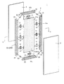
図2(a)は、図1(a)に示す蓄熱パネル1を、壁材として柱7Aと間柱7Bの間に取付ける方法を説明するための模式的斜視図であり、図2(b)は、図1(b)に示す蓄熱パネル1を柱7Aと間柱7Bの間に取付けた状態の模式的断面図である。
2. FIG. 2A is a schematic perspective view for explaining a method of attaching the
図2(a),(b)に示すように、蓄熱パネル1は、柱7Aおよび間柱7Bの設置面7aに接触させた状態で、蓄熱パネル1の長手方向に沿った周縁に、釘またはネジ等の固定具70を用いて取り付けられる。
As shown in FIGS. 2A and 2B, the
具体的には、蓄熱パネル1の表面側から、固定具70の先端部を、表面側のシート材4、パネル材2の固定部22、および裏面側のシート材4を順次貫通させて、柱7Aまたは間柱7Bに埋設させる。これにより、蓄熱パネル1は、柱7Aと間柱7Bとの間に固定される。
Specifically, from the front side of the
本実施形態によれば、蓄熱パネル1のパネル材2の含浸部21に潜熱蓄熱材が含浸されているので、蓄熱パネル1に入熱される熱を潜熱蓄熱材で蓄熱し、これを放熱することができる。
According to this embodiment, since the latent heat storage material is impregnated in the
ここで、固定部22には、熱硬化させた熱硬化性樹脂または潜熱蓄熱材よりも融点の高い熱可塑性樹脂が含浸されているので、含浸部21から固定部22に向かう潜熱蓄熱材は固定部22には含浸されない。すなわち、含浸部21から固定部22に向かう潜熱蓄熱材は固定部22により遮断される。
Here, since the fixing
したがって、蓄熱パネル1の固定部22に固定具70を貫通させて、蓄熱パネル1を設置面7aに固定したとしても、固定具70により固定部22に形成された貫通孔から含浸部21の潜熱蓄熱材が漏洩または揮発することはない。このような結果、設置面7aに固定された蓄熱パネル1の蓄熱性能の低下を防止することができる。また、固定部22には、上述した熱硬化性樹脂または熱可塑性樹脂が含浸されているので、未含浸のものに場合に比べて、その強度を高めることができる。
Therefore, even if the
3.蓄熱パネル1の製造方法について
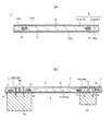
以下に、図1に示す蓄熱パネル1の製造方法を図3を参照しながら説明する。図3(a)〜(d)は、図1(a)に示す蓄熱パネル1のパネル材2を製造する工程を説明するための模式図である。
3. About the manufacturing method of the
まず、蓄熱パネル1のパネル材2の大きさに相当する1枚の多孔質基材2Aを準備する。次に、図3(a)に示すように、多孔質基材2Aの一方側の短辺縁部2a(固定部に相当する部分)を、浸漬槽8A内の未硬化の熱硬化性樹脂、または、溶融した熱可塑性樹脂からなる樹脂2Bに浸漬する。熱可塑性樹脂は、上述した潜熱蓄熱材の相変化温度よりも高い融点を有するものである。これにより、多孔質基材2Aの一方側の短辺縁部2aに樹脂2Bが含浸された、固定部22(の一部)が形成される。
First, one
次に、多孔質基材2Aを回転させて、図3(b)に示すように、多孔質基材2Aの一方側の長辺縁部2b(固定部に相当する部分)を、浸漬槽8A内の樹脂2Bに浸漬する。これにより、多孔質基材2Aの長辺縁部2bに、樹脂2Bが含浸された固定部22(の一部)が形成される。さらに、多孔質基材2Aを回転させて、他方側の短辺縁部2aおよび他方側の長辺縁部2bも同様に、浸漬槽8A内の樹脂2Bに順次、浸漬する。含浸した樹脂2Bが熱硬化性樹脂である場合には、その後加熱して、未硬化の熱硬化性樹脂を硬化させる。このようにして、多孔質基材2Aに固定部22が形成される。
Next, the
次に、図3(c)に示すように、固定部22が形成された多孔質基材2Aを、浸漬槽8B内の潜熱蓄熱材2Cに浸漬する。潜熱蓄熱材2Cは、浸漬槽8B内に溶融した状態で収容されている。これにより、図3(d)に示すように、含浸部21に相当する多孔質基材2Aの中央部分に潜熱蓄熱材2Cが含浸されたパネル材2を製造することができる。
Next, as shown in FIG.3 (c), 2 A of porous base materials in which the fixing | fixed
次に、パネル材2の両側から、含浸部21の表面21aと、含浸部21の表面21aに隣接した固定部22の表面22aと、を少なくとも覆うように、これらの両側から一対のシート材4,4を配置する(たとえば図1(a)参照)。
Next, a pair of
最後に、熱圧装置を用いて、両側のシート材4,4を、含浸部21の表面21aに隣接した固定部22の表面22aに熱圧することにより、シート材4を、パネル材2に接合する。これにより、図1(a)および図1(b)に示す蓄熱パネル1を得ることができる。本実施形態では、この熱圧により、シート材4の熱可塑性樹脂が、パネル材2に含浸される。
Finally, the
上述したように、本実施形態では、シート材4の熱可塑性樹脂をパネル材2に融着させることにより、シート材4をパネル材2に接合している。しかしながら、シート材4とパネル材2との間に、熱可塑性樹脂の接着剤、または未硬化の熱硬化性樹脂の接着剤を配置し、熱圧により、シート材4とパネル材2とを接合してもよい。
As described above, in the present embodiment, the
〔第2実施形態〕
図4は、本発明の第2実施形態に係る蓄熱パネル1の模式的分解斜視図である。図5(a)は、図4のB−B線矢視断面図であり、図5(b)は、図5(a)に示す蓄熱パネル1を柱7Aと間柱7Bの間に取付けた状態の断面図である。第2実施形態に係る蓄熱パネル1が、第1実施形態のものと相違する点は、パネル材2の構造である。その他の構成は、第1実施形態と同じであるので、同じ符号を付して詳細な説明を省略する。
[Second Embodiment]
FIG. 4 is a schematic exploded perspective view of the
図4に示すように、本実施形態では、含浸部21は、多孔質基材に潜熱蓄熱材が含浸された含浸パネル21Aであり、固定部22は、含浸部21(含浸パネル21A)を保持するように含浸部21(含浸パネル21A)の周縁を囲う枠体22Aである。図4および図5(a)に示すように、含浸部21(含浸パネル21A)と固定部22(枠体22A)との間には、含浸部21(含浸パネル21A)から固定部22(枠体22A)に向かう潜熱蓄熱材を遮断する遮断部材5が配置されている。
As shown in FIG. 4, in this embodiment, the
蓄熱パネル1の含浸部21に相当する含浸パネル21Aには、第1実施形態と同様に、潜熱蓄熱材が含浸されている。枠体22Aには、潜熱蓄熱材は含浸されておらず、枠体22Aの材料としては、例えば、広葉樹や針葉樹からなる通常の合板、パーティクルボード(PB)、木質繊維板(MDF・インシュレーションボード・ハードボードなど)、配向性ストランドボード(OSB)、LVL、集成材、クラフト紙、ボール紙、樹脂成型体、樹脂発砲体、または金属中空棒材を枠状態に組み合わせたものなどを挙げることができ、特にその材質は限定されない。
The
遮断部材5は、含浸パネル21Aの周縁を囲うように配置されており、遮断部材5が配置された含浸パネル21Aが、枠体22Aの貫通孔22bに嵌合している。遮断部材5は、溶融した潜熱蓄熱材が非透過な材料からなり、たとえば、シート材4で例示した熱可塑性樹脂製または金属製のフィルムまたはテープなどを挙げることができる。
The blocking
本実施形態に係る蓄熱パネル1によれば、図5(b)に示すように、含浸部21(含浸パネル21A)と固定部22(枠体22A)との間に配置された遮断部材5により、含浸部21から固定部22に向かう潜熱蓄熱材を遮断することができる。この結果、固定部22である枠体22Aに固定具70を貫通させて、蓄熱パネル1を設置面7aに設置しても、含浸部21の潜熱蓄熱材が外部に漏洩または揮発することがない。
According to the
〔第3実施形態〕
図6は、本発明の第3実施形態に係る蓄熱パネル1の模式的分解斜視図である。図7(a)は、図6のC−C線矢視断面図であり、図7(b)は、図7(a)に示す蓄熱パネル1を柱7Aと間柱7Bの間に取付けた状態の断面図である。第3実施形態に係る蓄熱パネル1が、第1実施形態のものと相違する点は、パネル材2の構造である。その他の構成は、第1実施形態と同じであるので、同じ符号を付して詳細な説明を省略する。
[Third Embodiment]
FIG. 6 is a schematic exploded perspective view of the
図6および図7(a)に示すように、パネル材2は、含浸部21と固定部22を有している。本実施形態では、含浸部21は、多孔質基材に潜熱蓄熱材が含浸された含浸パネル21Aであり、固定部22は、含浸部21を保持するように含浸部21の周縁を囲う無孔質の枠体22Bである。枠体22Bとしては、樹脂成型体、金属中空棒材を枠状態に組み合わせたものなどを挙げることができ、溶融した潜熱蓄熱材に対して非透であれば特にその材質は限定されない。
As shown in FIGS. 6 and 7A, the
枠体22Bは、枠体22Bの骨格となる4つの柱状の枠構成材22cを備えている。各枠構成材22cは、第1連結部材51を介して、含浸パネル21Aに連結されている。具体的には、各枠構成材22cの側面には、第1凹部26が形成されている。含浸パネル21Aには、含浸パネル21Aの周縁に枠体22Bを囲った状態で、第1凹部26に対向する位置に、第2凹部27が形成されている。第1連結部材51は、第1凹部26および第2凹部27に嵌合している。
The
さらに、枠構成材22c同士は、第2連結部材52を介して、相互に連結されている。具体的には、枠構成材22cの両端に第3凹部28が形成されており、含浸パネル21Aの周縁に枠体22Bを囲った状態で、隣接する枠構成材22c同士の第3凹部28が、1つの凹部を形成する。本実施形態では、第2連結部材52は、第3凹部28同士に嵌合している。
Further, the frame
第3実施形態では、第1連結部材51および第2連結部材52を用いて、いわゆる「雇いざねはぎ」により、パネル材2と枠構成材22cの連結、枠構成材22c同士の連結を行った。しかしながら、すり合わせはぎ(芋はぎ、平はぎ)、相欠きはぎ、本ざねはぎ、蟻ざねはぎ、相互はぎ、傾斜はぎ、だぼはぎ、木ねじはぎ、蟻くさびはぎ、または、端ばめはぎ等のきばばき(巾つぎ)で、これらの連結を行ってもよく、接着剤またはステープルなどでこれらの連結を行ってもよい。
In the third embodiment, the first connecting
本実施形態に係る蓄熱パネル1によれば、図7(b)に示すように、固定部22を無孔質の枠体22Bとすることにより、含浸部21から固定部22に向かう潜熱蓄熱材を遮断することができる。この結果、固定部22である枠体22Bに固定具70を貫通させて、蓄熱パネル1を設置面7aに設置しても、含浸部21の潜熱蓄熱材が外部に漏洩または揮発することがない。パネル材2を製造する際には、多孔質基材に潜熱蓄熱材を含浸した含浸パネル21Aを、無孔質の枠体22Bに組み付ければよいので、他の態様に比べて、蓄熱パネル1を簡単に製造することができる。
According to the
〔第4実施形態〕
図8は、本発明の第4実施形態に係る蓄熱パネル1の模式的分解斜視図である。図9(a)は、図8のD−D線矢視断面図であり、図9(b)は、図9(a)に示す蓄熱パネル1を柱7Aと間柱7Bの間に取付けた状態の断面図である。第4実施形態に係る蓄熱パネル1が、第1実施形態のものと相違する点は、シート材4の構造である。その他の構成は、第1実施形態と同じであるので、同じ符号を付して詳細な説明を省略する。
[Fourth Embodiment]
FIG. 8 is a schematic exploded perspective view of the
シート材4には、蓄熱パネル1を固定するための固定用目印が設けられている。具体的には、各シート材4には、固定用目印として、シート材4を貫通する貫通孔41が形成されている。各貫通孔41は、パネル材2の固定部22に対応した位置に形成されており、貫通孔41から固定部22が露出している。本実施形態では、図9(a)に示すように、蓄熱パネル1の厚さ方向に沿って、各シート材4に形成された貫通孔41が一致するように、貫通孔41が形成されている。
The
本実施形態に係る蓄熱パネル1によれば、図9(b)に示すように、各貫通孔41を蓄熱パネル1の固定用の目印として、パネル材2の含浸部21ではなく固定部22に、固定具70を貫通させて、柱7Aと間柱7Bの間に蓄熱パネル1を固定することができる。
According to the
固定具70が貫通する蓄熱パネル1の厚さ方向には、各シート材4の貫通孔41が形成されているので、蓄熱パネル1の裏面側のシート材4の貫通孔41に固定具70が挿通される。この結果、蓄熱パネル1を固定する際に、固定具70で裏面側(柱7Aまたは間柱7B側)のシート材4が浮き上がることがないので、裏面側のシート材4とパネル材2との接合性(密着性)を保持することができる。
Since the through
以上、本発明の実施形態について詳述したが、本発明は、前記の実施形態に限定されるものではなく、特許請求の範囲に記載された本発明の精神を逸脱しない範囲で、種々の設計変更を行うことができるものである。 Although the embodiments of the present invention have been described in detail above, the present invention is not limited to the above-described embodiments, and various designs can be made without departing from the spirit of the present invention described in the claims. It can be changed.
たとえば、本実施形態では、パネル材の表面の大きさと同じシート材を準備し、シート材を枠体に接合したが、含浸部をシート材で覆うことができれば、シート材の大きさは、実施形態のシート材の大きさよりも小さくてもよい。 For example, in the present embodiment, a sheet material having the same size as the surface of the panel material is prepared, and the sheet material is joined to the frame. However, if the impregnated portion can be covered with the sheet material, the size of the sheet material is It may be smaller than the size of the sheet material in the form.
また、第4実施形態に係るシート材の構造を、第2または第3実施形態に係るシート材に適用してもよい。 Further, the structure of the sheet material according to the fourth embodiment may be applied to the sheet material according to the second or third embodiment.
1:蓄熱パネル、2:パネル材、2A:多孔質基材、21:含浸部、21A:含浸パネル、22:固定部、22A,22B:枠体、4:シート材 1: heat storage panel, 2: panel material, 2A: porous substrate, 21: impregnation part, 21A: impregnation panel, 22: fixing part, 22A, 22B: frame, 4: sheet material
Claims (4)
多孔質基材に前記潜熱蓄熱材が含浸された含浸部と、前記含浸部の周りに形成され、前記蓄熱パネルを設置面に固定するための固定具が貫通する固定部と、を有したパネル材と、
前記パネル材の両側から、前記含浸部の表面と、前記含浸部の表面に隣接した固定部の表面と、を少なくとも覆うシート材と、を備え、
前記蓄熱パネルは、前記含浸部から前記固定部に向かう前記潜熱蓄熱材を遮断するように構成されていることを特徴とする蓄熱パネル。 A heat storage panel having a latent heat storage material,
A panel having an impregnation portion in which a porous base material is impregnated with the latent heat storage material, and a fixing portion which is formed around the impregnation portion and through which a fixture for fixing the heat storage panel to an installation surface passes. Material,
From both sides of the panel material, a sheet material that covers at least the surface of the impregnation part and the surface of the fixing part adjacent to the surface of the impregnation part,
The said thermal storage panel is comprised so that the said latent-heat thermal storage material which goes to the said fixing | fixed part from the said impregnation part may be interrupted | blocked.
Priority Applications (1)
| Application Number | Priority Date | Filing Date | Title |
|---|---|---|---|
| JP2016060030A JP6726991B2 (en) | 2016-03-24 | 2016-03-24 | Heat storage panel |
Applications Claiming Priority (1)
| Application Number | Priority Date | Filing Date | Title |
|---|---|---|---|
| JP2016060030A JP6726991B2 (en) | 2016-03-24 | 2016-03-24 | Heat storage panel |
Publications (2)
| Publication Number | Publication Date |
|---|---|
| JP2017172883A true JP2017172883A (en) | 2017-09-28 |
| JP6726991B2 JP6726991B2 (en) | 2020-07-22 |
Family
ID=59971910
Family Applications (1)
| Application Number | Title | Priority Date | Filing Date |
|---|---|---|---|
| JP2016060030A Active JP6726991B2 (en) | 2016-03-24 | 2016-03-24 | Heat storage panel |
Country Status (1)
| Country | Link |
|---|---|
| JP (1) | JP6726991B2 (en) |
Cited By (1)
| Publication number | Priority date | Publication date | Assignee | Title |
|---|---|---|---|---|
| US20170370656A1 (en) * | 2014-12-26 | 2017-12-28 | Eidai Co., Ltd. | Heat reservoir impregnated with latent heat storage material with excellent thermostability |
-
2016
- 2016-03-24 JP JP2016060030A patent/JP6726991B2/en active Active
Cited By (1)
| Publication number | Priority date | Publication date | Assignee | Title |
|---|---|---|---|---|
| US20170370656A1 (en) * | 2014-12-26 | 2017-12-28 | Eidai Co., Ltd. | Heat reservoir impregnated with latent heat storage material with excellent thermostability |
Also Published As
| Publication number | Publication date |
|---|---|
| JP6726991B2 (en) | 2020-07-22 |
Similar Documents
| Publication | Publication Date | Title |
|---|---|---|
| US8753473B2 (en) | Composite structural elements and method of making same | |
| CA2994271C (en) | Wall structure penetration attachment | |
| WO2013026172A1 (en) | Construction board with defined air permeability | |
| JP4361863B2 (en) | Matt-like inorganic fiber heat insulating material and its packaging | |
| KR101611949B1 (en) | insulation | |
| JP2017172883A (en) | Heat storage panel | |
| JP6928326B2 (en) | Double structural material | |
| ES2874497T3 (en) | Procedure for making a panel with at least two layers and a panel with at least two layers | |
| JP3834161B2 (en) | Insulated floor structure | |
| JP6639299B2 (en) | Thermal storage panel and method of manufacturing the same | |
| KR20170120384A (en) | Sandwich panel and method of producing the same | |
| CN206633142U (en) | Crosswise lamination wood plank | |
| KR101856760B1 (en) | Construction Method for Insulation and Waterproof Combined Multi-function Exterior Panel for Apartment Houses | |
| JPH11117453A (en) | Construction board | |
| JP7439233B1 (en) | Laminate and covering structure | |
| KR101537006B1 (en) | Complex Insulation Panel Comprising waterproof·moistureproof layer | |
| JP7291285B1 (en) | Underfloor material and floor structure | |
| JP6826374B2 (en) | Composite building material with heat storage body and its manufacturing method | |
| JP6711492B2 (en) | Fixture and waterproof structure | |
| JP4309899B2 (en) | Insulation for outer joints such as steel columns and heat insulation structure using the same | |
| JP6711491B2 (en) | Fixture and waterproof structure | |
| JP2022137841A (en) | Laminate and coating structure | |
| JP7423220B2 (en) | Fireproof wood components | |
| JP2022137842A (en) | Laminate and coating structure | |
| ES2385001B1 (en) | MULTI-PAPER PREFABRICATED PANEL AND PROCEDURE FOR ASSEMBLY AT WORK. |
Legal Events
| Date | Code | Title | Description |
|---|---|---|---|
| A621 | Written request for application examination |
Free format text: JAPANESE INTERMEDIATE CODE: A621 Effective date: 20181203 |
|
| A977 | Report on retrieval |
Free format text: JAPANESE INTERMEDIATE CODE: A971007 Effective date: 20191025 |
|
| A131 | Notification of reasons for refusal |
Free format text: JAPANESE INTERMEDIATE CODE: A131 Effective date: 20191203 |
|
| A521 | Written amendment |
Free format text: JAPANESE INTERMEDIATE CODE: A523 Effective date: 20200130 |
|
| TRDD | Decision of grant or rejection written | ||
| A01 | Written decision to grant a patent or to grant a registration (utility model) |
Free format text: JAPANESE INTERMEDIATE CODE: A01 Effective date: 20200616 |
|
| A61 | First payment of annual fees (during grant procedure) |
Free format text: JAPANESE INTERMEDIATE CODE: A61 Effective date: 20200630 |
|
| R150 | Certificate of patent or registration of utility model |
Ref document number: 6726991 Country of ref document: JP Free format text: JAPANESE INTERMEDIATE CODE: R150 |