JP2017172601A - Transmission structure for vehicle - Google Patents
Transmission structure for vehicle Download PDFInfo
- Publication number
- JP2017172601A JP2017172601A JP2016055938A JP2016055938A JP2017172601A JP 2017172601 A JP2017172601 A JP 2017172601A JP 2016055938 A JP2016055938 A JP 2016055938A JP 2016055938 A JP2016055938 A JP 2016055938A JP 2017172601 A JP2017172601 A JP 2017172601A
- Authority
- JP
- Japan
- Prior art keywords
- shift fork
- shaft
- transmission
- fork shaft
- shift
- Prior art date
- Legal status (The legal status is an assumption and is not a legal conclusion. Google has not performed a legal analysis and makes no representation as to the accuracy of the status listed.)
- Pending
Links
- 230000005540 biological transmission Effects 0.000 title claims abstract description 60
- 230000002093 peripheral effect Effects 0.000 claims description 10
- 230000004323 axial length Effects 0.000 claims description 6
- 230000000149 penetrating effect Effects 0.000 claims description 5
- 238000002485 combustion reaction Methods 0.000 description 4
- 238000013016 damping Methods 0.000 description 4
- 230000000694 effects Effects 0.000 description 4
- 125000002066 L-histidyl group Chemical group [H]N1C([H])=NC(C([H])([H])[C@](C(=O)[*])([H])N([H])[H])=C1[H] 0.000 description 3
- 230000006835 compression Effects 0.000 description 3
- 238000007906 compression Methods 0.000 description 3
- 239000002828 fuel tank Substances 0.000 description 2
- 230000001737 promoting effect Effects 0.000 description 2
- 230000005489 elastic deformation Effects 0.000 description 1
Images


Classifications
-
- F—MECHANICAL ENGINEERING; LIGHTING; HEATING; WEAPONS; BLASTING
- F16—ENGINEERING ELEMENTS AND UNITS; GENERAL MEASURES FOR PRODUCING AND MAINTAINING EFFECTIVE FUNCTIONING OF MACHINES OR INSTALLATIONS; THERMAL INSULATION IN GENERAL
- F16H—GEARING
- F16H57/00—General details of gearing
- F16H57/0006—Vibration-damping or noise reducing means specially adapted for gearings
-
- F—MECHANICAL ENGINEERING; LIGHTING; HEATING; WEAPONS; BLASTING
- F16—ENGINEERING ELEMENTS AND UNITS; GENERAL MEASURES FOR PRODUCING AND MAINTAINING EFFECTIVE FUNCTIONING OF MACHINES OR INSTALLATIONS; THERMAL INSULATION IN GENERAL
- F16H—GEARING
- F16H3/00—Toothed gearings for conveying rotary motion with variable gear ratio or for reversing rotary motion
- F16H3/02—Toothed gearings for conveying rotary motion with variable gear ratio or for reversing rotary motion without gears having orbital motion
- F16H3/08—Toothed gearings for conveying rotary motion with variable gear ratio or for reversing rotary motion without gears having orbital motion exclusively or essentially with continuously meshing gears, that can be disengaged from their shafts
-
- F—MECHANICAL ENGINEERING; LIGHTING; HEATING; WEAPONS; BLASTING
- F16—ENGINEERING ELEMENTS AND UNITS; GENERAL MEASURES FOR PRODUCING AND MAINTAINING EFFECTIVE FUNCTIONING OF MACHINES OR INSTALLATIONS; THERMAL INSULATION IN GENERAL
- F16H—GEARING
- F16H55/00—Elements with teeth or friction surfaces for conveying motion; Worms, pulleys or sheaves for gearing mechanisms
- F16H55/02—Toothed members; Worms
- F16H55/14—Construction providing resilience or vibration-damping
-
- B—PERFORMING OPERATIONS; TRANSPORTING
- B60—VEHICLES IN GENERAL
- B60Y—INDEXING SCHEME RELATING TO ASPECTS CROSS-CUTTING VEHICLE TECHNOLOGY
- B60Y2200/00—Type of vehicle
- B60Y2200/10—Road Vehicles
- B60Y2200/12—Motorcycles, Trikes; Quads; Scooters
-
- F—MECHANICAL ENGINEERING; LIGHTING; HEATING; WEAPONS; BLASTING
- F16—ENGINEERING ELEMENTS AND UNITS; GENERAL MEASURES FOR PRODUCING AND MAINTAINING EFFECTIVE FUNCTIONING OF MACHINES OR INSTALLATIONS; THERMAL INSULATION IN GENERAL
- F16H—GEARING
- F16H57/00—General details of gearing
- F16H57/02—Gearboxes; Mounting gearing therein
- F16H2057/02039—Gearboxes for particular applications
- F16H2057/02043—Gearboxes for particular applications for vehicle transmissions
- F16H2057/02065—Gearboxes for particular applications for vehicle transmissions for motorcycles or squads
-
- F—MECHANICAL ENGINEERING; LIGHTING; HEATING; WEAPONS; BLASTING
- F16—ENGINEERING ELEMENTS AND UNITS; GENERAL MEASURES FOR PRODUCING AND MAINTAINING EFFECTIVE FUNCTIONING OF MACHINES OR INSTALLATIONS; THERMAL INSULATION IN GENERAL
- F16H—GEARING
- F16H63/00—Control outputs from the control unit to change-speed- or reversing-gearings for conveying rotary motion or to other devices than the final output mechanism
- F16H63/02—Final output mechanisms therefor; Actuating means for the final output mechanisms
- F16H63/30—Constructional features of the final output mechanisms
- F16H2063/3079—Shift rod assembly, e.g. supporting, assembly or manufacturing of shift rails or rods; Special details thereof
-
- F—MECHANICAL ENGINEERING; LIGHTING; HEATING; WEAPONS; BLASTING
- F16—ENGINEERING ELEMENTS AND UNITS; GENERAL MEASURES FOR PRODUCING AND MAINTAINING EFFECTIVE FUNCTIONING OF MACHINES OR INSTALLATIONS; THERMAL INSULATION IN GENERAL
- F16H—GEARING
- F16H57/00—General details of gearing
Landscapes
- Engineering & Computer Science (AREA)
- General Engineering & Computer Science (AREA)
- Mechanical Engineering (AREA)
- General Details Of Gearings (AREA)
- Gear-Shifting Mechanisms (AREA)
- Vibration Dampers (AREA)
Abstract
Description
本発明は、車両用変速機構造に関する。 The present invention relates to a vehicle transmission structure.
従来、変速機の変速操作機構として、変速操作によって回動するシフトドラムと、シフトドラムの回動によりシフトフォークシャフトにスライド可能に支持されたシフトフォークとを備え、シフトフォークの移動によって変速段を切り換えるものが知られている(例えば、特許文献1参照)。
シフトフォークシャフトの両端部は、クランクケースに形成されたボス部27aで支持されている。
2. Description of the Related Art Conventionally, a shift operation mechanism of a transmission has been provided with a shift drum that is rotated by a shift operation and a shift fork that is slidably supported on a shift fork shaft by the rotation of the shift drum. What is switched is known (see, for example, Patent Document 1).
Both end portions of the shift fork shaft are supported by boss portions 27a formed on the crankcase.
上記の変速操作機構において、シフトドラムによるシフトフォークのスライド移動時に、シフトフォークとシフトフォークシャフトとの傾き状態によっては、シフトフォークが、シフトフォークシャフトを伴って一体にスライドする状態が発生する。このため、ボス部が、シフトフォークシャフトが軸方向に移動可能な深さに形成されているが、急なシフト操作が行われると、シフトフォークシャフトが勢いよくボス部内を摺動し、シフトフォークシャフトの端部がボス部の底面に向かって移動する場合がある。 In the above speed change operation mechanism, when the shift fork is slid by the shift drum, depending on the inclination state of the shift fork and the shift fork shaft, the shift fork slides integrally with the shift fork shaft. For this reason, the boss portion is formed to such a depth that the shift fork shaft can move in the axial direction. However, if a sudden shift operation is performed, the shift fork shaft slides in the boss portion vigorously, and the shift fork The end portion of the shaft may move toward the bottom surface of the boss portion.
そのため、シフトフォークシャフトの端部がボス部の底面に衝突することによる打音が発生する課題があるが、これを回避するための手段の一つとしては、上記の変速操作機構のように、一方のシフトフォークをシフトフォークシャフトに一体化することで、他方のシフトフォークの移動に引きずられることがなくなり、またこの一方のシフトフォークシャフトの移動に対しては、シフトフォークシャフトの移動範囲を一致させることで、ボス部との衝突前に移動規制することができる。
しかしながら、このようにシフトフォークとシフトフォークシャフトとを一体化した場合には、シフトフォーク自体の移動にともなう抵抗だけでなく、シフトフォークシャフトの摺動にともなう抵抗に抗ってシフト操作する必要から、スムーズなシフト操作を達成することが難しかった。
本発明の目的は、シフトフォークシャフトの両軸端とボス部の底面との衝突による打音の発生を回避するとともに変速機のスムーズなシフト操作を可能にする車両用変速機構造を提供することにある。
Therefore, there is a problem that a hitting sound is generated due to the end of the shift fork shaft colliding with the bottom surface of the boss, but as one of means for avoiding this, as in the above-described shift operation mechanism, By integrating one shift fork into the shift fork shaft, it will not be dragged by the movement of the other shift fork, and the movement range of the shift fork shaft matches the movement of this one shift fork shaft By doing so, it is possible to restrict movement before the collision with the boss portion.
However, in the case where the shift fork and the shift fork shaft are integrated in this way, it is necessary to perform a shift operation against the resistance due to the sliding of the shift fork shaft as well as the resistance due to the movement of the shift fork itself. It was difficult to achieve a smooth shift operation.
An object of the present invention is to provide a vehicle transmission structure that avoids the occurrence of hitting sound caused by a collision between both shaft ends of a shift fork shaft and the bottom surface of a boss portion and enables a smooth shift operation of the transmission. It is in.
上述した課題を解決するため、本発明は、変速機(82)の変速操作機構(170)に、変速操作に応じて回動するシフトドラム(177)と、前記変速機(82)の変速機ケース(1600)に支持されたシフトフォークシャフト(123)と、前記シフトフォークシャフト(123)に軸方向移動可能に支持されたシフトフォーク(124)とを備え、前記シフトドラム(177)の回動により軸方向に移動された前記シフトフォーク(124)と共に前記変速機(82)の変速軸(125)上に位置する変速歯車が軸方向移動して変速段が切り換えられる車両用変速機構造において、前記シフトフォークシャフト(123)の両端部は、前記変速機(82)のボス部(83e,116a)にそれぞれ移動可能に嵌合され、前記ボス部(83e,116a)の底面(83g,116c)と前記シフトフォークシャフト(123)の両端面(123c,123c)との間に隙間が設けられ、前記シフトフォークシャフト(123)の両軸端にダンパ部材(145)が設けられることを特徴とする。 In order to solve the above-described problems, the present invention provides a shift operation mechanism (170) of a transmission (82), a shift drum (177) that rotates in response to the shift operation, and a transmission of the transmission (82). A shift fork shaft (123) supported by a case (1600) and a shift fork (124) supported by the shift fork shaft (123) so as to be axially movable are provided, and the shift drum (177) rotates. In the vehicular transmission structure in which a shift gear positioned on the transmission shaft (125) of the transmission (82) is moved in the axial direction together with the shift fork (124) moved in the axial direction by an axial movement, and the gear position is switched. Both end portions of the shift fork shaft (123) are movably fitted to boss portions (83e, 116a) of the transmission (82), respectively, and the boss portion ( 3e, 116a) is provided with a gap between the bottom surface (83g, 116c) of the shift fork shaft (123) and both end surfaces (123c, 123c) of the shift fork shaft (123). (145) is provided.
上記構成において、前記ダンパ部材(145)は、弾性部材で構成され、前記ボス部(83e,116a)の底面(83g,116c)に当接する先端面(145d)に向かうにつれて先細りとなる断面台形形状に形成されても良い。
また、上記構成において、前記ダンパ部材(145)の先端面(145d)は、前記ボス部(83e,116a)の底面(83g,116c)側に開口して軸方向に延びる孔(145c)が形成されていても良い。
The said structure WHEREIN: The said damper member (145) is comprised with an elastic member, and the cross-sectional trapezoid shape which tapers toward the front end surface (145d) contact | abutted to the bottom face (83g, 116c) of the said boss | hub part (83e, 116a). May be formed.
In the above configuration, the front end surface (145d) of the damper member (145) is formed with a hole (145c) that opens to the bottom surface (83g, 116c) side of the boss portion (83e, 116a) and extends in the axial direction. May be.
また、上記構成において、前記孔は、前記ダンパ部材(145)を軸方向に貫通する貫通孔(145c)で構成されても良い。
また、上記構成において、前記ダンパ部材(145)は、前記ボス部(83e,116a)の底面(83g,116c)と当接可能な先端面(145d)とは反対側の端部が、前記シフトフォークシャフト(123)の内周面に嵌め込まれることで保持されても良い。
また、上記構成において、前記ダンパ部材(145)は、円筒形状に形成され、前記円筒形状の中心軸線(145g)に一致させて前記ダンパ部材(145)を貫通する前記孔(145c)が形成されていても良い。
Moreover, the said structure WHEREIN: The said hole may be comprised by the through-hole (145c) which penetrates the said damper member (145) to an axial direction.
In the above configuration, the end of the damper member (145) on the opposite side of the tip surface (145d) that can contact the bottom surface (83g, 116c) of the boss portion (83e, 116a) You may hold | maintain by being fitted by the internal peripheral surface of a fork shaft (123).
Further, in the above configuration, the damper member (145) is formed in a cylindrical shape, and the hole (145c) penetrating the damper member (145) is formed so as to coincide with the cylindrical central axis (145g). May be.
また、上記構成において、前記ダンパ部材(145)は、前記シフトフォークシャフト(123)の内周面に嵌り込む小径部(145a)と、前記ボス部(83e,116a)の底面(83g,116c)に面する先端面(145d)が形成された大径部(145b)とを有し、前記大径部(145b)に前記シフトフォークシャフト(123)の端面(123c)に当接して嵌め込み位置を規制する位置決め部(145f)が一体に形成されていても良い。
また、上記構成において、前記小径部(145a)の軸方向長さは、前記大径部(145b)の軸方向長さよりも長くされていても良い。
In the above configuration, the damper member (145) includes a small-diameter portion (145a) that fits into the inner peripheral surface of the shift fork shaft (123), and bottom surfaces (83g, 116c) of the boss portions (83e, 116a). And a large-diameter portion (145b) formed with a front end surface (145d) that faces the end surface (123c) of the shift fork shaft (123). The positioning part (145f) to be controlled may be formed integrally.
Moreover, the said structure WHEREIN: The axial direction length of the said small diameter part (145a) may be made longer than the axial direction length of the said large diameter part (145b).
本発明のシフトフォークシャフトの両端部は、変速機のボス部にそれぞれ移動可能に嵌合され、ボス部の底面とシフトフォークシャフトの両端面との間に隙間が設けられ、シフトフォークシャフトの両軸端にダンパ部材が設けられるので、シフトフォークシャフトの両軸端にダンパ部材を設けることで、シフトフォークシャフトの端面とボス部の底部との直接の衝突による打音の発生を防止することができる。また、シフトフォークの移動にともない、シフトフォークシャフトとは分離して移動が可能となるため、シフト操作時におけるシフトフォーク自体の抵抗は発生するものの、必ずシフトフォークシャフトとボス部との摺動抵抗が発生することがないので、変速機のスムーズなシフト操作を可能にすることができる。 Both end portions of the shift fork shaft of the present invention are movably fitted to the boss portions of the transmission, and a gap is provided between the bottom surface of the boss portion and both end surfaces of the shift fork shaft. Since the damper member is provided at the shaft end, by providing the damper member at both shaft ends of the shift fork shaft, it is possible to prevent the occurrence of hitting sound due to a direct collision between the end surface of the shift fork shaft and the bottom of the boss portion. it can. Also, as the shift fork moves, it can be moved separately from the shift fork shaft. Therefore, although resistance of the shift fork itself occurs during the shift operation, the sliding resistance between the shift fork shaft and the boss part is always required. Therefore, a smooth shift operation of the transmission can be made possible.
また、ダンパ部材は、弾性部材で構成され、ボス部の底面に当接する先端面に向かうにつれて先細りとなる断面台形形状に形成されているので、ダンパ部材がボス部の底面に当たったときにダンパ部材が弾性変形しやすくなり、ダンピング効果を高めることができる。
また、ダンパ部材の先端面は、ボス部の底面側に開口して軸方向に延びる孔が形成されているので、ダンパ部材の弾性変形を一層促すことができて、ダンピング効果を増すことができる。
Further, the damper member is made of an elastic member, and is formed in a trapezoidal cross-sectional shape that tapers toward the tip surface that contacts the bottom surface of the boss portion. Therefore, when the damper member hits the bottom surface of the boss portion, the damper member is formed. The member is easily elastically deformed, and the damping effect can be enhanced.
In addition, since the front end surface of the damper member is formed with a hole that opens to the bottom surface side of the boss portion and extends in the axial direction, it is possible to further promote elastic deformation of the damper member and increase the damping effect. .
また、孔は、前記ダンパ部材(145)を軸方向に貫通する貫通孔(145c)で構成されるので、シフトフォークの移動に伴ってシフトフォークシャフトが軸方向に移動する際に、ボス部内に滞留する空気又はオイルを孔を通じてシフトフォーク内に逃がすことができるので、シフトフォークシャフトの移動を阻害する空気又はオイルの影響を無くして、シフト操作をスムーズに行うことができる。また、シフトフォークシャフトの両軸端のダンパ部材に貫通する孔が空いていると、ボス部の底面に一端側のダンパ部材が当たったときに、他端側のダンパ部材の孔からシフトフォークシャフト内の空気又はオイルをボス部内に排出してシフトフォークシャフト内の圧力上昇を抑えることができ、このことからも、シフトフォークシャフトの軸方向移動を促してシフト操作をスムーズに行うことができる。 Further, since the hole is constituted by a through hole (145c) that penetrates the damper member (145) in the axial direction, when the shift fork shaft moves in the axial direction as the shift fork moves, Since the staying air or oil can be released into the shift fork through the hole, the shift operation can be performed smoothly without the influence of the air or oil hindering the movement of the shift fork shaft. Also, if there is a hole that penetrates the damper member at both shaft ends of the shift fork shaft, when the damper member at one end hits the bottom surface of the boss portion, the shift fork shaft from the hole of the damper member at the other end side The internal air or oil can be discharged into the boss portion to suppress an increase in pressure in the shift fork shaft. This also facilitates the shift operation by promoting the axial movement of the shift fork shaft.
また、ダンパ部材は、ボス部の底面と当接可能な先端面とは反対側の端部が、シフトフォークシャフトの内周面に嵌め込まれることで保持されているので、シフトフォークシャフトの軸端へのダンパ部材の取付けを簡素な構造で達成できる。
また、ダンパ部材は、円筒形状に形成され、円筒形状の中心軸線に一致させてダンパ部材を貫通する孔が形成されているので、シフトフォークシャフトの嵌め込み作業の際に、半径方向に均等な圧縮変形を促して嵌め込み作業が容易に行えるとともに、嵌め込み後の均等な緊迫力を発揮させて脱落を抑制することができる。
In addition, since the damper member is held by fitting the end portion on the opposite side of the tip surface that can come into contact with the bottom surface of the boss portion into the inner peripheral surface of the shift fork shaft, the shaft end of the shift fork shaft The damper member can be attached to the door with a simple structure.
Further, the damper member is formed in a cylindrical shape, and a hole penetrating the damper member is formed so as to coincide with the central axis of the cylindrical shape. Therefore, when the shift fork shaft is fitted, the damper member is uniformly compressed in the radial direction. In addition to facilitating deformation, the fitting operation can be easily performed, and the uniform tightening force after the fitting can be exerted to suppress the dropout.
また、ダンパ部材は、シフトフォークシャフトの内周面に嵌り込む小径部と、ボス部の底面に面する先端面が形成された大径部とを有し、大径部にシフトフォークシャフトの端面に当接して嵌め込み位置を規制する位置決め部が一体に形成されているので、シフトフォークシャフトの形状を変更することなく、ダンパ部材として単一構造によって位置決め部を構成でき、部品点数増加を抑制できる。
また、小径部の軸方向長さは、大径部の軸方向長さよりも長くされているので、シフトフォークシャフトの軸端への嵌めこみ長さを長くしてダンパ部材の脱落を抑制することができる。
The damper member has a small-diameter portion that fits into the inner peripheral surface of the shift fork shaft, and a large-diameter portion formed with a tip surface facing the bottom surface of the boss portion, and the end surface of the shift fork shaft at the large-diameter portion. Since the positioning part that abuts against and restricts the fitting position is integrally formed, the positioning part can be configured by a single structure as a damper member without changing the shape of the shift fork shaft, and an increase in the number of parts can be suppressed. .
Moreover, since the axial length of the small diameter portion is longer than the axial length of the large diameter portion, the fitting length of the shift fork shaft to the shaft end is lengthened to suppress the damper member from falling off. Can do.
以下、図面を参照して本発明の一実施形態について説明する。なお、説明中、前後左右および上下といった方向の記載は、特に記載がなければ車体に対する方向と同一とする。また、各図に示す符号FRは車体前方を示し、符号UPは車体上方を示し、符号LHは車体左方を示している。
図1は、本発明の車両用変速機構造を備える自動二輪車10を示す左側面図である。
自動二輪車10は、車体フレーム11、フロントフォーク12、ハンドル13、前輪14、パワーユニット16、排気装置17、リアフォーク18及び後輪21を備える車両である。
車体フレーム11は、ヘッドパイプ23、左右一対のメインフレーム24、左右一対のピボットプレート25、左右一対のシートレール26を備える。
Hereinafter, an embodiment of the present invention will be described with reference to the drawings. In the description, descriptions of directions such as front and rear, right and left and up and down are the same as directions with respect to the vehicle body unless otherwise specified. Further, in each figure, the symbol FR indicates the front of the vehicle body, the symbol UP indicates the upper side of the vehicle body, and the symbol LH indicates the left side of the vehicle body.
FIG. 1 is a left side view showing a
The
The
ヘッドパイプ23は、車体フレーム11の前端部に配置され、フロントフォーク12を操舵可能に支持している。メインフレーム24は、ヘッドパイプ23から左右の後方斜め下方に延びている。メインフレーム24の下部にはパワーユニット16が支持され、上部には燃料タンク31が支持されている。ピボットプレート25は、メインフレーム24の後部に接続されている。シートレール26は、ピボットプレート25の前部及び後部から後方斜め上方に延びている。シートレール26の前部にはシート33が支持され、後部にはグラブレール34及びトランクボックス35が支持されている。
The
フロントフォーク12の上部にはハンドル13が取付けられ、下部には車軸37を介して前輪14が支持されている。排気装置17は、パワーユニット16から延びる排気管(不図示)と、排気管の後端に取付けられたマフラ38とを備える。
リアフォーク18は、ピボットプレート25に設けられたピボット軸27に上下揺動可能に支持され、リアフォーク18の後端部に設けられた車軸39で後輪21が支持されている。リアフォーク18の後端部と車体フレーム11との間にはリアクッションユニット(不図示)が設けられている。
A
The
シート33は、燃料タンク31の後方に配置され、運転者が着座する運転者用シート31Aと、運転者用シート31Aの後方に一段高く形成されて同乗者が着座する同乗者用シート31Bと、同乗者用の背もたれ部31Cとを備えている。また、車体フレーム11のピボットプレート25には、運転者が足を載せる左右一対の運転者用ステップ42と、同乗者が足を載せる左右一対の同乗者用ステップ43とが取付けられている。また、車体フレーム11には、メインスタンド44、サイドスタンド46及び車体カバー47が取付けられている。
The
車体カバー47は、車体前方を覆うフロントカウル51と、車体側部を覆う左右一対のサイドカウル52と、車体下部を覆うアンダーカウル53と、車体後部を覆うリアカウル54とを備える。フロントカウル51には、ウインドスクリーン56を自動で上下動させる風防装置57が設けられている。リアカウル54には、左右一対のサイドバック58が一体に形成されている。また、フロントフォーク12には前輪14を上方から覆うフロントフェンダ61が取付けられ、リアカウル54には後輪21を上方から覆うリアフェンダ62が取付けられている。
The
フロントカウル51には、前面にヘッドライト65、上部にウインドスクリーン56、左右端にフロントウインカ66を内蔵する左右一対のミラー67が設けられ、フロントカウル51の内側には、メータ68が配置されている。
サイドカウル52には、車両前方からの外気をパワーユニット16の周囲に供給するための左右一対のエア開口69が設けられている。また、パワーユニット16の左右前方には、左右一対のエンジンガード71が設けられ、エンジンガード71にそれぞれフォグランプ72が取付けられている。
トランクボックス35には、背面に左右一対のテールランプユニット74、右側部にオーディオユニットがラジオ放送を受信する際に使用するロッドアンテナ75が設けられている。サイドバック58の背面には、リアウインカー76が配置されている。
The
The
The
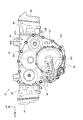
図2は、パワーユニット16を示す背面図である。図3は、パワーユニット16を示す平面図である。
図2及び図3に示すように、パワーユニット16は、上部を構成する内燃機関81と、内燃機関81の下部及び後部に一体的に設けられた変速機82とを備える。
内燃機関81は、水平対向型であり、車幅方向中央に設けられたクランクケース83と、クランクケース83の車幅方向外側に水平に延びるように取付けられた左シリンダヘッド84及び右シリンダヘッド86と、左シリンダヘッド84及び右シリンダヘッド86のそれぞれの開口を塞ぐ左ヘッドカバー87及び右ヘッドカバー88とを備える。
クランクケース83は、左右に分割された左ケース83A及び右ケース83Bからなる。左ケース83Aの左方に突出する左端部83c、左シリンダヘッド84及び左ヘッドカバー87は、左シリンダ部91を構成する。また、右ケース83Bの右方に突出する右端部83d、右シリンダヘッド86及び右ヘッドカバー88は、右シリンダ部92を構成する。
FIG. 2 is a rear view showing the
As shown in FIGS. 2 and 3, the
The
The
クランクケース83の後端面にはリヤクランクカバー94が取付けられている。また、リヤクランクカバー94の下部の中央には、車体後方側に椀状に膨出するクラッチカバー95が取付けられている。クラッチカバー95の内側にはクラッチ112(図4参照)が配置されている。なお、符号97は左ケース83A内に設けられたオイルポンプユニットである。
内燃機関81は、クランクケース83内に車両前後方向に延びるように収容されたクランク軸101を備える。また、変速機82は、クランク軸101の下方にメイン軸103、メイン軸103の右方にカウンタ軸104、カウンタ軸104の右斜め上方に出力軸106を備える。メイン軸103、カウンタ軸104及び出力軸106は、それぞれクランク軸101と平行に配置されている。
A rear crank
The
メイン軸103及びカウンタ軸104には、異なる歯車比での選択的な動力伝達が可能な複数段の歯車列が設けられている。これらの歯車列の歯車要素の噛み合いの組み合わせは、運転者によるシフト操作によって適宜行われる。出力軸106は、リヤクランクカバー94から車体後方側に突出している。出力軸106は、カウンタ軸104から動力を受けて回転し、その回転をドライブシャフト等の動力伝達部材を介して後輪21(図1参照)に伝達する。
The
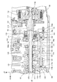
図4は、パワーユニット16の要部を示す断面図である。
変速機32は、減速機構111、クラッチ112、クラッチ軸114、メイン軸103、ミッションホルダ116、カム式ダンパー118、メイン軸歯車群121、シフトフォークシャフト123、複数のシフトフォーク124及びシフトドラム177を備える。
クラッチ112は、その入力側にクランク軸101の動力が減速機構111を介して伝達される。クラッチ軸114は、クラッチ112の出力側に一端が取付けられるとともに中間部がクランクケース83に設けられた軸受113で支持されている。メイン軸103は、一端がクラッチ軸114の他端に相対回転可能に支持されるとともに、他端が変速機ケース160に備えるミッションホルダ116に軸受117を介して支持されている。上記のクラッチ軸114及びメイン軸103は、変速軸125を構成する。
FIG. 4 is a cross-sectional view showing a main part of the
The
In the clutch 112, the power of the
カム式ダンパー118は、クラッチ軸114及びメイン軸103のそれぞれの間に設けられ、クラッチ軸114からメイン軸103へ所定のトルクを越える過大なトルクやトルク変動が入力されたときに相対回転することで、メイン軸103への過大なトルクやトルク変動の伝達を緩和する。メイン軸歯車群121は、メイン軸103上に設けられた複数の変速歯車からなる。
シフトフォークシャフト123は、変速機ケース160に形成された軸支持部83eと、ミッションホルダ116に形成された軸支持部116aとに両端部が支持された中空の軸である。シフトフォーク124は、シフトフォークシャフト123に軸方向移動可能に支持されるとともに、変速操作により、シフトドラム177の回動に伴ってメイン軸歯車群121の所定の変速歯車をメイン軸103上で軸方向移動させることで変速段を切り換えることが可能になる。
上記したシフトフォークシャフト123及びシフトフォーク124は、変速操作機構170の一部を構成し、手動変速操作による入力動作を受けて変速段ギヤを選択し、変速段を切り換える。
The
The
The
図5は、シフトフォークシャフトアッシー146を示す断面図である。
シフトフォークシャフト123は、真直な筒状の部品であり、その外周面123aにシフトフォーク124(図4参照)が移動可能に嵌合される。シフトフォークシャフト123の両端部には、ゴム製のキャップ145が嵌められている。上記のシフトフォークシャフト123及び一対のキャップ145,145は、シフトフォークシャフトアッシー146を構成する。
FIG. 5 is a sectional view showing the shift
The
キャップ145は、シフトフォークシャフト123の内周面123bに圧入される円柱状の軸部145aと、軸部145aの一端部に一体に形成された断面略台形状の頭部145bとからなる。なお、符号145gはキャップ145の軸方向に延びる中心軸線である。
軸部145a及び頭部145bには、キャップ145をシフトフォークシャフト123に嵌めた際にシフトフォークシャフト123内外を連通させるように軸方向に貫通孔145cが開けられている。貫通孔145cは、キャップ145の中心軸線145g上に一致するよう形成されている。
頭部145bは、その先端面145dに向かうにつれて次第に先細りとなるテーパ部145eと、シフトフォークシャフト123の端面123cに当てられる当接面145fとが形成されている。
The
A through
The
このように、シフトフォークシャフト123の両端部に弾性部材であるキャップ145,145を嵌めることで、図4において、シフトフォーク124の移動に伴って、シフトフォークシャフト123が、変速機ケース160の軸支持部83eに形成されたシャフト支持穴83fと、ミッションホルダ116の軸支持部116aに形成されたシャフト支持穴116bとを軸方向に移動する際に、キャップ145が、シャフト支持穴83fの底面83g又はシャフト支持穴116bの底面116cに当たったとしても、打音の発生を抑制することができる。
In this way, by fitting the
また、キャップ145がシャフト支持穴83fの底面83g(又はシャフト支持穴116bの底面116c)に当たったときに、シャフト支持穴83f(又はシャフト支持穴116b)の内部に溜まった空気又はオイルを当った側のキャップ145の貫通孔14cから、シフトフォークシャフト123内に排出することができる。あるいは、シフトフォークシャフト123内の空気又はオイルを当たった側とは反対側のキャップ145の貫通孔145cからシャフト支持穴116b(又はシャフト支持穴83f)へ排出することができる。これによって、キャップ145をスムーズに撓ませることができ、また、シフトフォークシャフト123をシフトフォーク124と共に軸方向移動しやすくして、シフト操作をスムーズに行うことができる。
When the
図4において、変速機ケース160の軸支持部83eは、軸受113を支持する軸受支持部161gに一体に接続されるとともに、カム式ダンパー118の半径方向外側に配置されている。軸支持部116aは、メイン軸103を支える部分でもあるため、この軸支持部116aに接続された軸支持部83eの剛性も高い部分となる。従って、シフト操作時にシフトフォークシャフトアッシー146がシャフト支持穴83fの底面83g側へ移動しようとした場合でも、これを阻害することなく、シフトフォークシャフト123の移動がよりスムーズに行われ、変速操作機構170のシフト操作をより一層スムーズに行うことができる。
In FIG. 4, the
上記の図4及び図6に示したように、変速機82の変速操作機構170に、変速操作に応じて回動するシフトドラム177と、変速機82の変速機ケース160に支持されたシフトフォークシャフト123と、シフトフォークシャフト123に軸方向移動可能に支持されたシフトフォーク124とを備え、シフトドラム177の回動により軸方向に移動されたシフトフォーク124と共に変速機82の変速軸125上に位置する変速歯車が軸方向移動して変速段が切り換えられる車両用変速機構造において、シフトフォークシャフト123の両端部は、変速機82のボス部としての軸支持部83e,116aにそれぞれ移動可能に嵌合され、軸支持部83e,116aの底面83g,116cとシフトフォークシャフト123の両端面123c,123cとの間に隙間が設けられ、シフトフォークシャフト123の両軸端にキャップ145が設けられる。
4 and 6, the
この構成によれば、シフトフォークシャフト123の両軸端にキャップ145を設けることで、シフトフォークシャフト123の端面123cと軸支持部83e,116aの底面83g,116cとの直接の衝突による打音の発生を防止することができる。また、シフトフォーク124の移動にともない、シフトフォークシャフト123とは分離して移動が可能となるため、シフト操作時におけるシフトフォーク124自体の抵抗は発生するものの、必ずシフトフォークシャフト123と軸支持部83e,116aとの摺動抵抗が発生することがないので、変速機82のスムーズなシフト操作を可能にすることができる。
According to this configuration, the
また、キャップ145は、弾性部材で構成され、軸支持部83e,116aの底面83g,116cに当接する先端面145dに向かうにつれて先細りとなる断面台形形状に形成されているので、キャップ145が軸支持部83e,116aの底面83g,116cに当たったときにキャップ145が弾性変形しやすくなり、ダンピング効果を高めることができる。
また、キャップ145の先端面145dは、軸支持部83e,116aの底面83g,116c側に開口して軸方向に延びる孔としての貫通孔145cが形成されているので、キャップ145の弾性変形を一層促すことができて、ダンピング効果を増すことができる。
Further, the
Further, since the
また、孔は、キャップ145を軸方向に貫通する貫通孔145cで構成されるので、シフトフォーク124の移動に伴ってシフトフォークシャフト123が軸方向に移動する際に、軸支持部83e,116a内に滞留する空気又はオイルを貫通孔145cを通じてシフトフォーク124内に逃がすことができるので、シフトフォークシャフト123の移動を阻害する空気又はオイルの影響を無くして、シフト操作をスムーズに行うことができる。また、シフトフォークシャフト123の両軸端のキャップ145に貫通する貫通孔145cが空いているので、軸支持部83e,116aの底面83g,116cの一方に一端側のキャップ145が当たったときに、他端側のキャップ145の貫通孔145cからシフトフォークシャフト123内の空気又はオイルを軸支持部83e,116aの他方に排出してシフトフォークシャフト123内の圧力上昇を抑えることができ、このことからも、シフトフォークシャフト123の軸方向移動を促してシフト操作をスムーズに行うことができる。
Further, since the hole is constituted by a through-
また、キャップ145は、軸支持部83e,116aの底面83g,116cと当接可能な先端面145dとは反対側の端部が、シフトフォークシャフト123の内周面123bに嵌め込まれることで保持されているので、シフトフォークシャフト123の軸端へのキャップ145の取付けを簡素な構造で達成することができる。
また、キャップ145は、円筒形状に形成され、円筒形状の中心軸線145gに一致させてキャップ145を貫通する貫通孔145cが形成されているので、シフトフォークシャフト123の嵌め込み作業の際に、半径方向に均等な圧縮変形を促して嵌め込み作業が容易に行えるとともに、嵌め込み後の均等な緊迫力を発揮させて脱落を抑制することができる。
The
Further, the
また、キャップ145は、シフトフォークシャフト123の内周面に嵌り込む小径部としての軸部145aと、軸支持部83e,116aの底面83g,116cに面する先端面145dが形成された大径部としての頭部145bとを有し、頭部145bにシフトフォークシャフト123の端面123cに当接して嵌め込み位置を規制する位置決め部としての当接面145fが一体に形成されているので、シフトフォークシャフト123の形状を変更することなく、キャップ145として単一構造によって当接面145fを構成でき、部品点数増加を抑制することができる。
また、軸部145aの軸方向長さは、頭部145bの軸方向長さよりも長くされているので、シフトフォークシャフト123の軸端への嵌めこみ長さを長くしてキャップ145の脱落を抑制することができる。
The
In addition, since the axial length of the
上述した実施形態は、あくまでも本発明の一態様を示すものであり、本発明の主旨を逸脱しない範囲で任意に変形及び応用が可能である。
例えば、上記実施形態において、図6に示したように、シフトフォークシャフト123の両軸端にゴム製のキャップ145を設けたが、これに限らず、シフトフォークシャフト123の端面123cと軸支持部83e,116aの底面83g,116cとの間に、弾性部材として円柱状のゴム部材又は圧縮コイルばねを設けても良い。又は、軸支持部83e,116aの底面83g,116cに、弾性部材として円柱状のゴム部材又は圧縮コイルばねを固定して、移動するシフトフォークシャフト123を受けとめるようにしても良い。何れの形態によっても、本発明はシフトフォークシャフト123と、軸支持部83e,116aとの間で移動の自由度を確保しながら、これらの衝突による打音の発生を抑制しながら、スムーズなシフト操作を可能にすることができるものである。
本発明は、自動二輪車10に適用する場合に限らず、自動二輪車10以外の車両にも適用可能である。
The above-described embodiment is merely an aspect of the present invention, and can be arbitrarily modified and applied without departing from the gist of the present invention.
For example, in the above embodiment, as shown in FIG. 6, the rubber caps 145 are provided at both shaft ends of the
The present invention is not limited to the case where the present invention is applied to the
10 自動二輪車(車両)
82 変速機
83e,116a 軸支持部(ボス部)
83g,116c 底面
123 シフトフォークシャフト
123c 端面
124 シフトフォーク
125 変速軸
145 キャップ(ダンパ部材)
145a 軸部(小径部)
145b 頭部(大径部)
145c 貫通孔(孔)
145d 先端面
145f 当接面(位置決め部)
145g 中心軸線
160 変速機ケース
170 変速操作機構
177 シフトドラム
10 Motorcycle (vehicle)
82
83g, 116c
145a Shaft part (small diameter part)
145b Head (large diameter part)
145c Through hole (hole)
Claims (8)
前記シフトフォークシャフト(123)の両端部は、前記変速機(82)のボス部(83e,116a)にそれぞれ移動可能に嵌合され、前記ボス部(83e,116a)の底面(83g,116c)と前記シフトフォークシャフト(123)の両端面(123c,123c)との間に隙間が設けられ、前記シフトフォークシャフト(123)の両軸端にダンパ部材(145)が設けられることを特徴とする車両用変速機構造。 The shift operation mechanism (170) of the transmission (82) has a shift drum (177) that rotates in response to the shift operation, and a shift fork shaft (supported by the transmission case (160) of the transmission (82)). 123) and a shift fork (124) supported on the shift fork shaft (123) so as to be axially movable, and the shift fork (124) moved in the axial direction by the rotation of the shift drum (177). ) Together with the transmission gear 82 on the transmission shaft (125) of the transmission (82) to move in the axial direction to change the gear position,
Both end portions of the shift fork shaft (123) are movably fitted to boss portions (83e, 116a) of the transmission (82), respectively, and bottom surfaces (83g, 116c) of the boss portions (83e, 116a). And a gap member is provided between both end faces (123c, 123c) of the shift fork shaft (123), and damper members (145) are provided at both shaft ends of the shift fork shaft (123). Vehicle transmission structure.
Priority Applications (3)
| Application Number | Priority Date | Filing Date | Title |
|---|---|---|---|
| JP2016055938A JP2017172601A (en) | 2016-03-18 | 2016-03-18 | Transmission structure for vehicle |
| US15/447,306 US9933065B2 (en) | 2016-03-18 | 2017-03-02 | Vehicular gear transmission structure |
| DE102017204199.4A DE102017204199A1 (en) | 2016-03-18 | 2017-03-14 | Vehicle transmission assembly |
Applications Claiming Priority (1)
| Application Number | Priority Date | Filing Date | Title |
|---|---|---|---|
| JP2016055938A JP2017172601A (en) | 2016-03-18 | 2016-03-18 | Transmission structure for vehicle |
Publications (1)
| Publication Number | Publication Date |
|---|---|
| JP2017172601A true JP2017172601A (en) | 2017-09-28 |
Family
ID=59751561
Family Applications (1)
| Application Number | Title | Priority Date | Filing Date |
|---|---|---|---|
| JP2016055938A Pending JP2017172601A (en) | 2016-03-18 | 2016-03-18 | Transmission structure for vehicle |
Country Status (3)
| Country | Link |
|---|---|
| US (1) | US9933065B2 (en) |
| JP (1) | JP2017172601A (en) |
| DE (1) | DE102017204199A1 (en) |
Cited By (2)
| Publication number | Priority date | Publication date | Assignee | Title |
|---|---|---|---|---|
| DE102019133964A1 (en) | 2018-12-21 | 2020-06-25 | Honda Motor Co., Ltd. | VEHICLE TRANSMISSION STRUCTURE |
| CN111810612A (en) * | 2020-07-02 | 2020-10-23 | 中国科学院合肥物质科学研究院 | Concentric shaft transmission mechanism for single-drive multidirectional intermittent output |
Families Citing this family (3)
| Publication number | Priority date | Publication date | Assignee | Title |
|---|---|---|---|---|
| JP2017172601A (en) * | 2016-03-18 | 2017-09-28 | 本田技研工業株式会社 | Transmission structure for vehicle |
| JP6722012B2 (en) * | 2016-03-18 | 2020-07-15 | 本田技研工業株式会社 | Vehicle transmission structure |
| CN112923049A (en) * | 2019-12-05 | 2021-06-08 | 舍弗勒技术股份两合公司 | Gear shifting device and gearbox |
Citations (4)
| Publication number | Priority date | Publication date | Assignee | Title |
|---|---|---|---|---|
| JPS55126149A (en) * | 1979-03-23 | 1980-09-29 | Yamaha Motor Co Ltd | Shifting device of speed change gear |
| JPS58187647U (en) * | 1982-06-09 | 1983-12-13 | 本田技研工業株式会社 | change equipment |
| JPS6092806U (en) * | 1983-11-30 | 1985-06-25 | 松下電工株式会社 | silence solenoid |
| JP2013194849A (en) * | 2012-03-21 | 2013-09-30 | Suzuki Motor Corp | Gear change device of transmission |
Family Cites Families (10)
| Publication number | Priority date | Publication date | Assignee | Title |
|---|---|---|---|---|
| US4448094A (en) * | 1981-07-13 | 1984-05-15 | Dana Corporation | Apparatus for switching engine governor |
| US4543846A (en) * | 1981-08-20 | 1985-10-01 | Toyota Jidosha Kabushiki Kaisha | Interlocking construction in transmission manipulation device for manual transmission |
| JP4270334B2 (en) * | 1999-01-11 | 2009-05-27 | 本田技研工業株式会社 | Always-mesh transmission for vehicle |
| JP2003148615A (en) | 2001-11-14 | 2003-05-21 | Suzuki Motor Corp | Transmission for motorcycle |
| JP2007071325A (en) * | 2005-09-08 | 2007-03-22 | Aisin Ai Co Ltd | Shift mechanism for manual transmission |
| JP5340978B2 (en) * | 2010-02-03 | 2013-11-13 | 本田技研工業株式会社 | Shift control device |
| JP5869459B2 (en) * | 2012-09-27 | 2016-02-24 | 本田技研工業株式会社 | Shift drum structure of drum transmission |
| JP5750485B2 (en) * | 2013-09-30 | 2015-07-22 | 本田技研工業株式会社 | Drum type variable speed drive |
| JP2017172601A (en) * | 2016-03-18 | 2017-09-28 | 本田技研工業株式会社 | Transmission structure for vehicle |
| JP6655440B2 (en) * | 2016-03-18 | 2020-02-26 | 本田技研工業株式会社 | Transmission structure for vehicles |
-
2016
- 2016-03-18 JP JP2016055938A patent/JP2017172601A/en active Pending
-
2017
- 2017-03-02 US US15/447,306 patent/US9933065B2/en not_active Expired - Fee Related
- 2017-03-14 DE DE102017204199.4A patent/DE102017204199A1/en not_active Withdrawn
Patent Citations (4)
| Publication number | Priority date | Publication date | Assignee | Title |
|---|---|---|---|---|
| JPS55126149A (en) * | 1979-03-23 | 1980-09-29 | Yamaha Motor Co Ltd | Shifting device of speed change gear |
| JPS58187647U (en) * | 1982-06-09 | 1983-12-13 | 本田技研工業株式会社 | change equipment |
| JPS6092806U (en) * | 1983-11-30 | 1985-06-25 | 松下電工株式会社 | silence solenoid |
| JP2013194849A (en) * | 2012-03-21 | 2013-09-30 | Suzuki Motor Corp | Gear change device of transmission |
Cited By (5)
| Publication number | Priority date | Publication date | Assignee | Title |
|---|---|---|---|---|
| DE102019133964A1 (en) | 2018-12-21 | 2020-06-25 | Honda Motor Co., Ltd. | VEHICLE TRANSMISSION STRUCTURE |
| JP2020101229A (en) * | 2018-12-21 | 2020-07-02 | 本田技研工業株式会社 | Vehicular transmission structure |
| US11168778B2 (en) | 2018-12-21 | 2021-11-09 | Honda Motor Co., Ltd. | Vehicle transmission structure |
| DE102019133964B4 (en) | 2018-12-21 | 2023-03-16 | Honda Motor Co., Ltd. | vehicle transmission assembly |
| CN111810612A (en) * | 2020-07-02 | 2020-10-23 | 中国科学院合肥物质科学研究院 | Concentric shaft transmission mechanism for single-drive multidirectional intermittent output |
Also Published As
| Publication number | Publication date |
|---|---|
| DE102017204199A1 (en) | 2017-09-21 |
| US9933065B2 (en) | 2018-04-03 |
| US20170268654A1 (en) | 2017-09-21 |
Similar Documents
| Publication | Publication Date | Title |
|---|---|---|
| JP2017172601A (en) | Transmission structure for vehicle | |
| EP2551180B1 (en) | Hybrid saddle-ridden vehicle | |
| EP2551181B1 (en) | Hybrid saddled vehicle | |
| US10794484B2 (en) | Transmission structure for vehicle | |
| JP6722012B2 (en) | Vehicle transmission structure | |
| AU2006202649B2 (en) | Rough terrain vehicle | |
| EP2927021B2 (en) | Wheel support mechanism | |
| JP4881685B2 (en) | Motorcycle | |
| US10436320B2 (en) | Transmission structure for vehicle | |
| JP2008149813A (en) | Power unit for vehicle | |
| JP6197481B2 (en) | Wind screen device | |
| JP5568351B2 (en) | Power unit for small vehicles | |
| JP2020023276A (en) | Motor cycle | |
| JP3155318U (en) | Saddle type vehicle engine and saddle type vehicle | |
| JP2019120260A (en) | Transmission of motor cycle | |
| JP2008049746A (en) | Transmission mechanism for motorcycle | |
| JP2015040025A (en) | Wind screen device | |
| JP2009281542A (en) | Front fork and motorcycle having this front fork | |
| JP2003129855A (en) | Engine structure of motorcycle | |
| JP2015040021A (en) | Wind screen device |
Legal Events
| Date | Code | Title | Description |
|---|---|---|---|
| A621 | Written request for application examination |
Free format text: JAPANESE INTERMEDIATE CODE: A621 Effective date: 20181127 |
|
| A977 | Report on retrieval |
Free format text: JAPANESE INTERMEDIATE CODE: A971007 Effective date: 20191004 |
|
| A131 | Notification of reasons for refusal |
Free format text: JAPANESE INTERMEDIATE CODE: A131 Effective date: 20191029 |
|
| A02 | Decision of refusal |
Free format text: JAPANESE INTERMEDIATE CODE: A02 Effective date: 20200428 |