JP2017172328A - Cast-in-place steel pipe concrete pile and steel pipe thereof - Google Patents
Cast-in-place steel pipe concrete pile and steel pipe thereof Download PDFInfo
- Publication number
- JP2017172328A JP2017172328A JP2017134536A JP2017134536A JP2017172328A JP 2017172328 A JP2017172328 A JP 2017172328A JP 2017134536 A JP2017134536 A JP 2017134536A JP 2017134536 A JP2017134536 A JP 2017134536A JP 2017172328 A JP2017172328 A JP 2017172328A
- Authority
- JP
- Japan
- Prior art keywords
- steel pipe
- concrete
- cast
- restraining
- place
- Prior art date
- Legal status (The legal status is an assumption and is not a legal conclusion. Google has not performed a legal analysis and makes no representation as to the accuracy of the status listed.)
- Granted
Links
Images


Abstract
Description
この発明は、場所打ち鋼管コンクリート杭及びその鋼管に関する。 The present invention relates to a cast-in-place steel pipe concrete pile and its steel pipe.
例えば、KCTB工法として知られている場所打ち鋼管コンクリート杭工法は、場所打ちコンクリート杭の頭部に、これを取り囲むように、スパイラル状の内面突起を有する鋼管を設置する工法である。 For example, the cast-in-place steel pipe concrete pile method known as the KCTB method is a method of installing a steel pipe having a spiral inner surface protrusion around the head of the cast-in-place concrete pile so as to surround it.
この工法によれば、杭頭部がスパイラル状突起によってコンクリートと一体化した鋼管で補強されるので、杭頭部の断面積を増やすことなく、大きな曲げモーメントやせん断力に対する必要な杭耐力が得られる。また、同時に高い変形性能(靱性)を得ることができ、より耐震性を向上させることができる。通常の鉄筋コンクリートだけの場所打ちコンクリート杭と比較して、杭頭部を細くすることができるため、拡底杭工法と組み合わせると、工期の短縮を図り、コンクリートや掘削残土の量を低減することができる。 According to this method, the pile head is reinforced with a steel pipe integrated with concrete by spiral protrusions, so the necessary pile strength against large bending moment and shear force can be obtained without increasing the cross-sectional area of the pile head. It is done. At the same time, high deformation performance (toughness) can be obtained, and the earthquake resistance can be further improved. Compared with cast-in-place concrete piles made of ordinary reinforced concrete, the pile head can be made thinner, so when combined with the expanded pile method, the construction period can be shortened and the amount of concrete and excavated soil can be reduced. .
しかしながら、スパイラル状の内面突起を有する鋼管は、多数の突条を有する帯状鋼板をスパイラル状に丸めることによって円筒形のものにするという製造方法によって作られるため、納期の問題やコストが高くなるという難点がある。 However, a steel pipe having a spiral inner protrusion is made by a manufacturing method in which a strip-shaped steel plate having a large number of protrusions is formed into a cylindrical shape by rounding it into a spiral shape, which leads to higher delivery problems and costs. There are difficulties.
また、場所打ちコンクリート杭工法には、鋼管内部をコンクリートのみとする場合(SCタイプ)と、鉄筋コンクリートとする場合(SRCタイプ)とがあるが、SRCタイプの場合、鉄筋籠は図12に示すようにして掘削孔に建て込まれる。すなわち、同図(a)に示すように、地盤に形成した掘削孔上部にケーシング50が建て込まれ、このケーシング50に鋼管51が預けられる。鉄筋籠52は一般には所定長さにユニット化され、この鉄筋籠ユニット52は順次接続しながら鋼管51の内部を通して掘削孔53に建て込まれる。
Moreover, in the cast-in-place concrete pile construction method, there are a case where the inside of the steel pipe is made of concrete only (SC type) and a case where the steel pipe is made of reinforced concrete (SRC type). In the case of the SRC type, the reinforcing bar is as shown in FIG. It is built in the excavation hole. That is, as shown in FIG. 2A, the
鉄筋籠ユニット52の外周には、鉄筋籠を掘削孔53の軸心に保持するための複数のスペーサ54が設けられている。しかしながら、鋼管51は上述のように内面にスパイラル状の突起55を有しているため(同図(b)参照)、鉄筋籠ユニット52が鋼管51内を通過できるようにするためには、スペーサ54の鉄筋籠ユニット52からの径方向突出寸法を小さくせざるをえない。その結果、スペーサ54は鋼管51を通過したものの、掘削孔53の孔壁から大きく離れることとなり、スペーサとしての機能を果たさなくなってしまう。
A plurality of
上記問題点に言及したものではないが、場所打ち鋼管コンクリート杭に関する先行技術文献としては例えば、以下に記すようなものを挙げることができる。 Although it does not mention the said problem, as what is described below as a prior art literature regarding a cast-in-place steel pipe concrete pile, the following can be mentioned, for example.
この発明は上記のような技術的背景に基づいてなされたものであって、次の目的を達成するものである。
この発明の目的は、コスト高となるスパイラル状突起を有する鋼管によらなくとも、鋼管とコンクリートとの一体化を図ることができ、加えて鉄筋籠が鋼管内を通過可能としつつ、スペーサの鉄筋籠からの突出寸法を掘削孔径に応じた適正なものとすることができ、それによって鉄筋籠を掘削孔軸心に保持することができる、場所打ち鋼管コンクリート杭及びその鋼管を提供することにある。
The present invention has been made based on the technical background as described above, and achieves the following object.
The object of the present invention is to integrate the steel pipe and the concrete without using a steel pipe having spiral projections, which increases the cost, and in addition, allows the reinforcing bar rod to pass through the steel pipe, while the reinforcing bar of the spacer. PROBLEM TO BE SOLVED: To provide a cast-in-place steel pipe concrete pile and its steel pipe, in which the projecting dimension from the ridge can be made appropriate according to the diameter of the digging hole, and thereby the reinforcing bar can be held in the digging hole axis. .
スペーサの鉄筋籠からの突出寸法を制限しているスパイラル状突起は、上述のように、コンクリートと鋼管との付着力を増し、硬化コンクリートの軸方向ずれを拘束するためのものである。そこで、この発明の発明者らは、鋭意検討を重ねた結果、鋼管内面に設ける突起をスパイラル状としなくとも、単にリング状のものとするだけで硬化コンクリートを十分に拘束することができることを見出した。しかし、依然として、スペーサの寸法が制限されるので、これを解決すべく次のような解決手段を見出した。 As described above, the spiral protrusions that limit the protruding dimension of the spacer from the reinforcing bar are for increasing the adhesive force between the concrete and the steel pipe and restraining the axial displacement of the hardened concrete. Thus, as a result of extensive studies, the inventors of the present invention have found that the hardened concrete can be sufficiently constrained by simply forming a ring-shaped protrusion on the inner surface of the steel pipe without using a spiral shape. It was. However, since the size of the spacer is still limited, the following solution has been found to solve this.
すなわち、この発明は、掘削孔上部に設置される鋼管と、外周に複数のスペーサを有し、前記鋼管内を通して前記掘削孔に建て込まれる鉄筋籠と、前記掘削孔に打設されるコンクリートとからなる場所打ち鋼管コンクリート杭であって、
前記鋼管の内周に該鋼管と硬化コンクリートとの間の軸方向ずれを拘束するための複数の拘束部材を周方向に間隔を置いて設け、前記鉄筋籠の建て込み時に前記スペーサが前記拘束部材間を通過可能としたことを特徴とする場所打ち鋼管コンクリート杭にある。
That is, this invention has a steel pipe installed at the upper part of the excavation hole, a plurality of spacers on the outer periphery, a reinforcing bar to be built into the excavation hole through the steel pipe, and a concrete to be cast into the excavation hole, A cast-in-place steel pipe concrete pile consisting of
A plurality of restraining members for restraining axial displacement between the steel pipe and the hardened concrete are provided at intervals in the circumferential direction on the inner periphery of the steel pipe, and the spacer is used when the reinforcing bar is installed. It is in a cast-in-place steel pipe concrete pile characterized by being able to pass between.
上記場所打ち鋼管コンクリート杭において、前記拘束部材の少なくとも直上であって前記鋼管の外周に補強部材を設けるとよい。また、前記拘束部材の下方であって前記鋼管の内周に、コンクリートのブリーディングによる分離水が前記拘束部材に向かって上昇するのを阻止するための複数のブリーディング処理部材を、前記拘束部材の間隔に対応した間隔を置いて設けるようにしてもよい。 In the cast-in-place steel pipe concrete pile, a reinforcing member may be provided at least directly above the restraining member and on the outer periphery of the steel pipe. Further, a plurality of bleeding treatment members for preventing the separated water due to the concrete bleeding from rising toward the restraining member below the restraining member and on the inner periphery of the steel pipe, It may be provided with an interval corresponding to.
また、この発明は、掘削孔上部に設置されて、その内部を通して外周に複数のスペーサを有する鉄筋籠が前記掘削孔に建て込まれる、場所打ち鋼管コンクリート杭用の鋼管であって、
内周に該鋼管と硬化コンクリートとの間の軸方向ずれを拘束するための複数の拘束部材を周方向に間隔を置いて設け、前記鉄筋籠の建て込み時に前記スペーサが前記拘束部材間を通過可能としたことを特徴とする場所打ち鋼管コンクリート杭用鋼管にある。
Further, the present invention is a steel pipe for a cast-in-place steel pipe concrete pile, which is installed in the upper part of the excavation hole, and a reinforcing bar having a plurality of spacers on the outer periphery is built in the excavation hole,
A plurality of restraining members for restraining axial displacement between the steel pipe and the hardened concrete are provided on the inner periphery at intervals in the circumferential direction, and the spacer passes between the restraining members when the reinforcing bar is installed. It is in cast-in-place steel pipe for concrete pile.
上記場所打ちコンクリート杭用鋼管において、前記拘束部材の少なくとも直上であって前記鋼管の外周に補強部材を設けるとよい。また、前記拘束部材の下方であって前記鋼管の内周に、コンクリートのブリーディングによる分離水が前記拘束部材に向かって上昇するのを阻止するための複数のブリーディング処理部材を、前記拘束部材の間隔に対応した間隔を置いて設けるようにしてもよい。 In the cast-in-place concrete pile steel pipe, a reinforcing member may be provided at least directly above the restraining member and on the outer periphery of the steel pipe. Further, a plurality of bleeding treatment members for preventing the separated water due to the concrete bleeding from rising toward the restraining member below the restraining member and on the inner periphery of the steel pipe, It may be provided with an interval corresponding to.
この発明によれば、鋼管の内周に複数の拘束部材を設けることによってコンクリートと鋼管との一体化を図るようにしたので、鋼管は通常の平鋼板を丸めたものを使用することができ、納期の短縮やコストを安価なものとすることができる。また、複数の拘束部材間には間隔が形成されているので、鉄筋籠の建て込み時にはスペーサが拘束部材間を通過することができる。これにより、スペーサの鉄筋籠からの突出寸法を、その先端が鋼管の内周にほぼ達する大きなものとすることができる。その結果、スペーサの外周端が掘削孔の孔壁近くに位置することとなり、スペーサは鉄筋籠を掘削孔の軸心に保持する本来の機能を発揮する。 According to the present invention, since the concrete and the steel pipe are integrated by providing a plurality of restraining members on the inner periphery of the steel pipe, the steel pipe can be obtained by rounding a normal flat steel sheet, The delivery time can be shortened and the cost can be reduced. In addition, since a space is formed between the plurality of restraining members, the spacer can pass between the restraining members when the reinforcing bar is installed. Thereby, the protrusion dimension from the reinforcing bar rod of a spacer can be made into the big thing which the front-end | tip almost reaches the inner periphery of a steel pipe. As a result, the outer peripheral end of the spacer is positioned near the hole wall of the excavation hole, and the spacer exhibits the original function of holding the reinforcing bar rod at the axial center of the excavation hole.
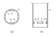
この発明の実施形態を図面を参照しながら以下に説明する。図1に示すように、鋼管1の下部内周には複数の拘束部材2が周方向に間隔dを置いて設けられている。拘束部材2は、鋼管1内に打設されて硬化したコンクリートが、鋼管1との間で軸方向にずれるのを拘束するためのものであり、所定の厚みを持った断面四角形の鋼材で作られている。拘束部材2は突起あるいは突条と言い換えることもでき、その厚みが突起あるいは突条の高さとなる。
Embodiments of the present invention will be described below with reference to the drawings. As shown in FIG. 1, a plurality of restraining
拘束部材2の個数すなわち間隔dの数は、鉄筋籠に設けられるスペーサの周方向の個数に応じた数であり、一般には杭径に応じて同一円周上に4〜8個設けられる。図示の例では拘束部材2は鋼管1の軸方向に関して一段であるが、複数段となるように配置してもよい。
The number of restraining
拘束部材2の周方向長さは、コンクリートに対する必要な拘束力の大きさに応じて増減することができる。必要な拘束力が小さくてよい場合、図2に示すように、周方向長さを短くすることができ、その結果、間隔dを大きくすることができる。
The circumferential length of the
拘束部材2は溶接により鋼管1の内周に固着されるが、ボルト止め等の他の手段によって固着してもよい。拘束部材2は図3,図4に示すように、種々の形態を採ることができる。同図(a)は、拘束部材2の両端に厚み(突起高さ)が徐々に減じるようなテーパ部3を設けた例である。このようなテーパ部3を設けることにより、間隔dは鋼管の内方側が広がることになるので、拘束部材2,2間をスペーサが通過しやすくなる。
The
同図(b)は拘束部材2の両端に溶接ビード5を盛って厚みを部分的に増加させた例である。これによって、コンクリートと鋼管1との付着力を増すことができる。同図(c)は、リング部材を溶接した後、そのリング部材を周方向に間隔を置いた複数箇所で研削して複数の拘束部材2を形成した例である。
FIG. 2B shows an example in which the
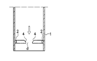
また、図4は拘束部材2の両端部に幅(鋼管の軸方向寸法)が徐々に減じるようなテーパ部4を設けた例を示している。このようなテーパ部4を設けることにより、間隔dは上方に向けて広がることになるので、図中矢印で示すスペーサの下降通過の際に、スペーサが拘束部材2,2間を通過しやすくなる。
FIG. 4 shows an example in which tapered portions 4 are provided at both ends of the restraining
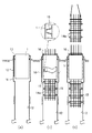
図5,図6は、上記鋼管1を使用した場所打ち鋼管コンクリート杭の概略施工手順を示している。図5(a)に示すように、アースドリル機等によりケーシング10用の孔11を先行掘削した後、さらにその下方に先行掘削孔11よりも小径の杭軸部用の孔12を掘削する。そして、先行掘削孔11にケーシング10を設置し、このケーシング10に支持具13を介して鋼管1を預ける。
5 and 6 show a schematic construction procedure of a cast-in-place steel pipe concrete pile using the
次いで、同図(b)に示すように、所定長さに製作された鉄筋籠ユニット14aを鋼管1内を通して軸部掘削孔12に建て込む。この鉄筋籠ユニット14aには周方向に間隔を置いて、また軸方向に間隔を置いて複数のスペーサ15が設けられている。スペーサ15は一般にU字形に作られ、開放側の両端部が鉛直方向上下にそれぞれ位置するように鉄筋籠ユニット14aに固着されている。
Next, as shown in FIG. 2B, the reinforcing
先行する鉄筋籠ユニット14aを建て込んだら、これを支持具16を介して鋼管1に仮受けし、同図(c)に示すように、後行する鉄筋籠ユニット14aを吊り下げて、その下端部を先行する鉄筋籠ユニット14aの上端部に接続する。
When the preceding reinforcing
以下、同様にして鉄筋籠ユニット14aを順次接続しながら軸部掘削孔12に建て込むことにより、図6(d)に示すように、所定長さの鉄筋籠14が構成される。鉄筋籠14を仮受けする支持具16は、鋼管1に固定されており、所定長さとされた鉄筋籠14は支持具16に溶接により固着される。すなわち、鉄筋籠14の上端部が支持具16を介して鋼管1の上端部に固定される。
Thereafter, similarly, the reinforcing
次に、同図(e)に示すように、鋼管1及び鉄筋籠14を、鋼管1の下端部が地盤上方の適宜高さに位置するまで一旦引き上げ、この鋼管1の下端部と鉄筋籠14とを複数の連結鉄筋17で連結し、鋼管1の下端部に鉄筋籠14を固定する。そして、同図(f)に示すように、鋼管1及び鉄筋籠14を軸部掘削孔12までに下降させ、杭天端をセットする。すなわち、ケーシング10に治具18を取付け、吊りバー19により鋼管1を所定の高さ位置に保持する。その後、図示しないが、掘削孔11,12のスライムを除去した後、掘削孔11,12にコンクリートを打設し、ケーシング10を引き抜いて施工を完了する。
Next, as shown in FIG. 4E, the
上記のような施工手順において、鉄筋籠ユニット14aを鋼管1内を通過させる際(図5(b)(c))、拘束部材2,2間には間隔dが形成されているので、スペーサ15は拘束部材2,2間を通過することができる。これにより、スペーサ15の鉄筋籠ユニット14aからの突出寸法を、その先端が鋼管1の内周にほぼ達する大きなものとすることができる。その結果、スペーサ15の外周端が軸部掘削孔12の孔壁近くに位置することとなり、スペーサ15は鉄筋籠14を軸部掘削孔12の軸心に保持する本来の機能を発揮する。
In the construction procedure as described above, when the reinforcing
ところで、上記のようにして築造されたコンクリート杭において、図7(a)に示すように、鋼管1内の硬化コンクリートCに押し抜き力Fが作用すると、拘束部材2がコンクリートCを支圧拘束し、押し抜き力に対して抵抗する。しかし、その一方、拘束部材2の直上のコンクリート部分が拘束部材2による支圧で拘束されるため、拘束による膨張作用が発生する。そして、コンクリートが支圧破壊するため、最終破壊形状としては同図(b)に示すように拘束部材2の直上が膨らんだ状態となり、その結果、鋼管1も提灯状態に膨張変形する。
By the way, in the concrete pile constructed as described above, when the punching force F acts on the hardened concrete C in the
鋼管1に作用する膨張圧と鋼管内周方向に発生する引張力との関係は、図8(a)を参照して、次のように表すことができる。
T(N) = p(N/mm) × D/2(mm) ・・・・・(1)
ただし、T:鋼管に発生する引張力
p:膨張等分布荷重
D:鋼管径
The relationship between the expansion pressure acting on the
T (N) = p (N / mm) x D / 2 (mm) (1)
T: Tensile force generated in steel pipe
p: Expansion load
D: Steel pipe diameter
ここで、鋼管厚をtとすると、鋼管円周方向応力度σsr(N/mm2) = T(N)/(t(mm)×1(mm))、また膨張圧σp(N/mm2) = p(N/mm2)/1(mm) より、(1)式は次のようになる。
σp = (2×t)・σsr/D ・・・・・(2)
Here, when the steel pipe thickness is t, the steel pipe circumferential stress σ sr (N / mm 2 ) = T (N) / (t (mm) × 1 (mm)) and the expansion pressure σ p (N / From mm 2 ) = p (N / mm 2) / 1 (mm), equation (1) is as follows.
σ p = (2 × t) · σ sr / D (2)
鋼管円周方向応力度σsrは、設計値で定められていることから、図8(b)に示すように、同一鋼管厚tでは鋼管径Dが大きくなるほど鋼管の耐えうる膨張圧いわゆる拘束圧が小さくなることになる。この拘束圧が大きいほど、コンクリートの押し抜き抵抗力が向上する。 Since the steel pipe circumferential direction stress σ sr is determined by a design value, as shown in FIG. 8 (b), the expansion pressure that the steel pipe can withstand as the steel pipe diameter D becomes larger at the same steel pipe thickness t, so-called restraint pressure. Will become smaller. The greater the restraining pressure, the more the punching resistance of concrete is improved.
そこで、この発明では拘束部材2の支圧拘束効果により拘束部材2の直上部に作用する応力に対して補強するため、図9に示すように、拘束部材2の直上部から直下部にわたって鋼管1の外周に補強部材21を設けた。拘束部材2の直上部のみならず、直下部にも補強部材21を設けたのは、押し抜き力とは逆方向のコンクリートの引抜き力によって生じる応力に対して補強するためである。
Therefore, in this invention, in order to reinforce against the stress acting on the upper part of the restraining
補強部材21は断面四角形の鋼材からなり、リング状に形成されているが、複数個を周方向に間隔を置いて部分的に設ける形態を採ってもよい。この補強部材21も拘束部材2のように溶接により鋼管1に固着されるが、ボルト止め等の他の手段を用いてもよい。このような補強部材21を設けることにより、(2)式における鋼管厚tが部分的に厚くなることから、コンクリートに対する拘束性能を向上させ、押し抜きや引抜き抵抗力を向上させることができる。なお、補強部材21は拘束部材2の直上部分から直下部分まで一体となっているが、拘束部材2の外周部分は必ずしも無くともよく、したがってこれら直上部分と直下部分は分離していてもよい。
The reinforcing
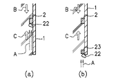
上述のように、拘束部材2はコンクリートの押し抜き力や引抜き力に抵抗する有効な手段であるが、コンクリートの打設後に発生するブリーディング現象によって拘束圧が働かないおそれがある。すなわち、図10(a)に示すように、コンクリートのブリーディングによって分離水が矢印Aのように上昇すると、拘束部材2の下部で遮られ、この部分に空洞などのコンクリートの不良部分22が発生する。
As described above, the restraining
そうすると、矢印B,Cで示す押し抜き力及び引抜き力のうち、引抜き力Cが拘束部材2に伝達せず、引抜き抵抗が不十分になってしまう。このような、ブリーディングに対処するためには、拘束部材の下方における鋼管1の内周に分離水が拘束部材2に向かって上昇するのを阻止するブリーディング処理部材23を設ければよい。これにより不良部分22はブリーディング処理部材23の下部に発生するが、拘束部材2の下部には発生せず、したがって拘束部材2は押し抜き力及び引抜き力B,Cの双方に対してコンクリートを拘束し、十分に抵抗することができる。
If it does so, drawing force C will not be transmitted to
ブリーディング処理部材23は、図11に示すように、拘束部材2と同様に断面四角形の部材であり、鋼管1の内周に間隔を置いて複数設けられている。ブリーディング処理部材23,23間の間隔は、鉄筋籠1のスペーサ15が通過できるように、拘束部材2,2間の間隔dに対応している。ブリーディング処理部材23の設置位置は、拘束部材2から離れすぎると処理効果が小さくなるので、拘束部材2の下方30cm以内とすることが望ましい。
As shown in FIG. 11, the bleeding processing
また、ブリーディング処理部材23は厚み(突起あるいは突条としての高さ)が拘束部材2の厚みと同等以上であることが望ましい。ブリーディング処理部材23は、その機能の点からは鋼材としなくともプラスチック材料等軽微な材料を用いることができるが、鋼材を使用することにより拘束部材2とともにコンクリートに対する拘束力を期待することができる。
Further, it is desirable that the thickness of the bleeding processing member 23 (height as a protrusion or a protrusion) is equal to or greater than the thickness of the restraining
1:鋼管
2:拘束部材
11,12:掘削孔
14:鉄筋籠ユニット
15:スペーサ
21:補強部材
23:ブリーディング処理部材
d:間隔
1: Steel pipe 2:
Claims (4)
A spacing corresponding to the spacing of the restraining members is provided on the inner periphery of the steel pipe below the restraining members, and a bleeding treatment member for preventing separation water due to concrete bleeding from rising toward the restraining members. The cast-in-place steel pipe for concrete according to claim 3, wherein the steel pipe is provided.
Priority Applications (1)
| Application Number | Priority Date | Filing Date | Title |
|---|---|---|---|
| JP2017134536A JP6406560B2 (en) | 2017-07-10 | 2017-07-10 | Cast-in-place steel pipe concrete pile and its steel pipe |
Applications Claiming Priority (1)
| Application Number | Priority Date | Filing Date | Title |
|---|---|---|---|
| JP2017134536A JP6406560B2 (en) | 2017-07-10 | 2017-07-10 | Cast-in-place steel pipe concrete pile and its steel pipe |
Related Parent Applications (1)
| Application Number | Title | Priority Date | Filing Date |
|---|---|---|---|
| JP2012095276A Division JP6213758B2 (en) | 2012-04-19 | 2012-04-19 | Cast-in-place steel pipe concrete pile and its construction method |
Publications (2)
| Publication Number | Publication Date |
|---|---|
| JP2017172328A true JP2017172328A (en) | 2017-09-28 |
| JP6406560B2 JP6406560B2 (en) | 2018-10-17 |
Family
ID=59970546
Family Applications (1)
| Application Number | Title | Priority Date | Filing Date |
|---|---|---|---|
| JP2017134536A Active JP6406560B2 (en) | 2017-07-10 | 2017-07-10 | Cast-in-place steel pipe concrete pile and its steel pipe |
Country Status (1)
| Country | Link |
|---|---|
| JP (1) | JP6406560B2 (en) |
Cited By (1)
| Publication number | Priority date | Publication date | Assignee | Title |
|---|---|---|---|---|
| CN112705652A (en) * | 2021-01-29 | 2021-04-27 | 天津和兴源建筑工程有限公司 | Concrete square pile reinforcement cage weaving equipment |
Citations (6)
| Publication number | Priority date | Publication date | Assignee | Title |
|---|---|---|---|---|
| JPS52107403U (en) * | 1976-02-12 | 1977-08-16 | ||
| JPS56142921A (en) * | 1980-04-03 | 1981-11-07 | Taisei Corp | Construction work of foundation of structure |
| JPS5771542U (en) * | 1980-10-14 | 1982-05-01 | ||
| JPS6332018A (en) * | 1986-07-23 | 1988-02-10 | Hasegawa Komuten Co Ltd | Formation of cast-in-place pile |
| JPH02296928A (en) * | 1989-05-09 | 1990-12-07 | Takenaka Komuten Co Ltd | H steel pile for placing soil cement |
| JP2010168734A (en) * | 2009-01-20 | 2010-08-05 | System Keisoku Kk | Steel pipe for pile and the pile |
-
2017
- 2017-07-10 JP JP2017134536A patent/JP6406560B2/en active Active
Patent Citations (6)
| Publication number | Priority date | Publication date | Assignee | Title |
|---|---|---|---|---|
| JPS52107403U (en) * | 1976-02-12 | 1977-08-16 | ||
| JPS56142921A (en) * | 1980-04-03 | 1981-11-07 | Taisei Corp | Construction work of foundation of structure |
| JPS5771542U (en) * | 1980-10-14 | 1982-05-01 | ||
| JPS6332018A (en) * | 1986-07-23 | 1988-02-10 | Hasegawa Komuten Co Ltd | Formation of cast-in-place pile |
| JPH02296928A (en) * | 1989-05-09 | 1990-12-07 | Takenaka Komuten Co Ltd | H steel pile for placing soil cement |
| JP2010168734A (en) * | 2009-01-20 | 2010-08-05 | System Keisoku Kk | Steel pipe for pile and the pile |
Cited By (2)
| Publication number | Priority date | Publication date | Assignee | Title |
|---|---|---|---|---|
| CN112705652A (en) * | 2021-01-29 | 2021-04-27 | 天津和兴源建筑工程有限公司 | Concrete square pile reinforcement cage weaving equipment |
| CN112705652B (en) * | 2021-01-29 | 2023-03-07 | 天津和兴源建筑工程有限公司 | Concrete square pile reinforcement cage weaving equipment |
Also Published As
| Publication number | Publication date |
|---|---|
| JP6406560B2 (en) | 2018-10-17 |
Similar Documents
| Publication | Publication Date | Title |
|---|---|---|
| JP6648990B2 (en) | Foundation structure | |
| JP2010001608A (en) | Pile head handling method in cast-in-place concrete pile construction method | |
| JP6213758B2 (en) | Cast-in-place steel pipe concrete pile and its construction method | |
| CN107532398B (en) | Rigid connection structure for lower end of support and concrete pile | |
| JP5978426B2 (en) | Calculation method of pulling resistance of pile | |
| JP6406560B2 (en) | Cast-in-place steel pipe concrete pile and its steel pipe | |
| JP2018003304A (en) | Anchor reinforcing structure, anchor reinforcing method and anchor reinforcing member | |
| JP2006249808A (en) | Joining structure of pile and footing | |
| JP6768477B2 (en) | How to build an underground structure | |
| JP5942342B2 (en) | Reinforcement structure of existing structures | |
| JP2016132948A (en) | Connection structure | |
| JP2016223208A (en) | Pile foundation structure | |
| JP7304248B2 (en) | Pile head connection structure and construction method of pile head connection structure | |
| JP2007170099A (en) | Method for preventing differential settlement by reducing liquefaction of existing building foundation | |
| JP6849523B2 (en) | Outer shell steel pipe concrete pile and its manufacturing method | |
| JP6522450B2 (en) | SC pile | |
| JP6233753B2 (en) | Pile head structure and construction method of pile head structure | |
| JP2008002180A (en) | Manhole | |
| JP6677564B2 (en) | Reinforced basket and connection method of reinforced basket | |
| KR100593182B1 (en) | Reinforcement structure of a pile for building | |
| KR20190122929A (en) | Pier Unification Method for Extended Rock Mass Boring | |
| JP2012136841A (en) | Method for excavating ground under spread foundation of existing building, and base-isolating method for existing building | |
| JP6419040B2 (en) | Mountain retaining structure and construction method of mountain retaining structure | |
| JP2005307512A (en) | Building and construction method of the same | |
| JP6229212B2 (en) | How to install underground pillars |
Legal Events
| Date | Code | Title | Description |
|---|---|---|---|
| A621 | Written request for application examination |
Free format text: JAPANESE INTERMEDIATE CODE: A621 Effective date: 20170710 |
|
| A521 | Request for written amendment filed |
Free format text: JAPANESE INTERMEDIATE CODE: A523 Effective date: 20170803 |
|
| A131 | Notification of reasons for refusal |
Free format text: JAPANESE INTERMEDIATE CODE: A131 Effective date: 20180709 |
|
| A521 | Request for written amendment filed |
Free format text: JAPANESE INTERMEDIATE CODE: A523 Effective date: 20180806 |
|
| TRDD | Decision of grant or rejection written | ||
| A01 | Written decision to grant a patent or to grant a registration (utility model) |
Free format text: JAPANESE INTERMEDIATE CODE: A01 Effective date: 20180823 |
|
| R150 | Certificate of patent or registration of utility model |
Ref document number: 6406560 Country of ref document: JP Free format text: JAPANESE INTERMEDIATE CODE: R150 |
|
| A61 | First payment of annual fees (during grant procedure) |
Free format text: JAPANESE INTERMEDIATE CODE: A61 Effective date: 20180905 |
|
| R250 | Receipt of annual fees |
Free format text: JAPANESE INTERMEDIATE CODE: R250 |
|
| R250 | Receipt of annual fees |
Free format text: JAPANESE INTERMEDIATE CODE: R250 |
|
| R250 | Receipt of annual fees |
Free format text: JAPANESE INTERMEDIATE CODE: R250 |