JP2017169425A - Indoor unit, air conditioner, and method of manufacturing indoor unit - Google Patents
Indoor unit, air conditioner, and method of manufacturing indoor unit Download PDFInfo
- Publication number
- JP2017169425A JP2017169425A JP2016055309A JP2016055309A JP2017169425A JP 2017169425 A JP2017169425 A JP 2017169425A JP 2016055309 A JP2016055309 A JP 2016055309A JP 2016055309 A JP2016055309 A JP 2016055309A JP 2017169425 A JP2017169425 A JP 2017169425A
- Authority
- JP
- Japan
- Prior art keywords
- shaft
- indoor unit
- fan motor
- housing
- forming member
- Prior art date
- Legal status (The legal status is an assumption and is not a legal conclusion. Google has not performed a legal analysis and makes no representation as to the accuracy of the status listed.)
- Pending
Links
Images


Classifications
-
- F—MECHANICAL ENGINEERING; LIGHTING; HEATING; WEAPONS; BLASTING
- F24—HEATING; RANGES; VENTILATING
- F24F—AIR-CONDITIONING; AIR-HUMIDIFICATION; VENTILATION; USE OF AIR CURRENTS FOR SCREENING
- F24F1/00—Room units for air-conditioning, e.g. separate or self-contained units or units receiving primary air from a central station
-
- F—MECHANICAL ENGINEERING; LIGHTING; HEATING; WEAPONS; BLASTING
- F24—HEATING; RANGES; VENTILATING
- F24F—AIR-CONDITIONING; AIR-HUMIDIFICATION; VENTILATION; USE OF AIR CURRENTS FOR SCREENING
- F24F13/00—Details common to, or for air-conditioning, air-humidification, ventilation or use of air currents for screening
- F24F13/20—Casings or covers
-
- F—MECHANICAL ENGINEERING; LIGHTING; HEATING; WEAPONS; BLASTING
- F24—HEATING; RANGES; VENTILATING
- F24F—AIR-CONDITIONING; AIR-HUMIDIFICATION; VENTILATION; USE OF AIR CURRENTS FOR SCREENING
- F24F1/00—Room units for air-conditioning, e.g. separate or self-contained units or units receiving primary air from a central station
- F24F1/0003—Room units for air-conditioning, e.g. separate or self-contained units or units receiving primary air from a central station characterised by a split arrangement, wherein parts of the air-conditioning system, e.g. evaporator and condenser, are in separately located units
-
- F—MECHANICAL ENGINEERING; LIGHTING; HEATING; WEAPONS; BLASTING
- F24—HEATING; RANGES; VENTILATING
- F24F—AIR-CONDITIONING; AIR-HUMIDIFICATION; VENTILATION; USE OF AIR CURRENTS FOR SCREENING
- F24F11/00—Control or safety arrangements
- F24F11/30—Control or safety arrangements for purposes related to the operation of the system, e.g. for safety or monitoring
-
- F—MECHANICAL ENGINEERING; LIGHTING; HEATING; WEAPONS; BLASTING
- F24—HEATING; RANGES; VENTILATING
- F24F—AIR-CONDITIONING; AIR-HUMIDIFICATION; VENTILATION; USE OF AIR CURRENTS FOR SCREENING
- F24F13/00—Details common to, or for air-conditioning, air-humidification, ventilation or use of air currents for screening
- F24F13/32—Supports for air-conditioning, air-humidification or ventilation units
-
- H—ELECTRICITY
- H02—GENERATION; CONVERSION OR DISTRIBUTION OF ELECTRIC POWER
- H02K—DYNAMO-ELECTRIC MACHINES
- H02K11/00—Structural association of dynamo-electric machines with electric components or with devices for shielding, monitoring or protection
- H02K11/40—Structural association with grounding devices
-
- H—ELECTRICITY
- H02—GENERATION; CONVERSION OR DISTRIBUTION OF ELECTRIC POWER
- H02K—DYNAMO-ELECTRIC MACHINES
- H02K5/00—Casings; Enclosures; Supports
- H02K5/04—Casings or enclosures characterised by the shape, form or construction thereof
- H02K5/16—Means for supporting bearings, e.g. insulating supports or means for fitting bearings in the bearing-shields
-
- F—MECHANICAL ENGINEERING; LIGHTING; HEATING; WEAPONS; BLASTING
- F24—HEATING; RANGES; VENTILATING
- F24F—AIR-CONDITIONING; AIR-HUMIDIFICATION; VENTILATION; USE OF AIR CURRENTS FOR SCREENING
- F24F1/00—Room units for air-conditioning, e.g. separate or self-contained units or units receiving primary air from a central station
- F24F1/06—Separate outdoor units, e.g. outdoor unit to be linked to a separate room comprising a compressor and a heat exchanger
- F24F1/20—Electric components for separate outdoor units
- F24F1/22—Arrangement or mounting thereof
Landscapes
- Engineering & Computer Science (AREA)
- Chemical & Material Sciences (AREA)
- Combustion & Propulsion (AREA)
- Mechanical Engineering (AREA)
- General Engineering & Computer Science (AREA)
- Power Engineering (AREA)
- Motor Or Generator Frames (AREA)
- Structures Of Non-Positive Displacement Pumps (AREA)
Abstract
Description
本発明は、空調機の室内機、当該室内機を備える空調機及び室内機の製造方法に関する。 The present invention relates to an indoor unit for an air conditioner, an air conditioner including the indoor unit, and a method for manufacturing the indoor unit.
近年の空気調和機用のファンモータは、一般に、インバータを用いてPWM(Pulse Width Modulation)方式で駆動させるインバータ駆動方式が用いられている。インバータ駆動方式を用いた場合、インバータのスイッチング制御に応じたコモンモードノイズがファンモータ内部を伝搬し、モータ巻線の中性点電位を変動させることが知られている。そうすると、モータ回転軸の軸受の外輪(ブラケット)と内輪(シャフト)との間に電位差(以下、「軸電圧」とも記載する。)が生じる。
軸電圧が軸受内部の油膜の絶縁破壊電圧に達すると軸受内部に微小電流が流れ、軸受内部に電食が発生する。電食が進行すると、軸受内輪、軸受外輪または軸受内輪と軸受外輪の間に設けられる軸受ボールに波状摩耗現象が発生して異常音に至ることがあり、ファンモータにおける不具合要因の1つとなっていた。
In recent years, fan motors for air conditioners generally use an inverter drive system that is driven by a PWM (Pulse Width Modulation) system using an inverter. When the inverter drive system is used, it is known that common mode noise according to inverter switching control propagates through the fan motor and fluctuates the neutral point potential of the motor winding. Then, a potential difference (hereinafter also referred to as “shaft voltage”) is generated between the outer ring (bracket) and the inner ring (shaft) of the bearing of the motor rotation shaft.
When the shaft voltage reaches the dielectric breakdown voltage of the oil film inside the bearing, a minute current flows inside the bearing, and electrolytic corrosion occurs inside the bearing. When electrolytic corrosion progresses, a wavy wear phenomenon may occur in the bearing inner ring, the bearing outer ring, or a bearing ball provided between the bearing inner ring and the bearing outer ring, resulting in abnormal noise, which is one of the causes of problems in fan motors. It was.
上述のような電食を防ぐための方法、即ち、軸電圧を低減するための方法として、種々の対策が提案されている。例えば、導電性を有するブラシ等を介して軸受内輪と軸受外輪とを接触(導通)状態にする方法が知られている。
また、軸と軸受外輪との間に別途の静電容量を付加することで軸電圧を低減する方法も開示されている(特許文献1を参照)。
この他、セラミックボール軸受を採用することにより、軸受内部油膜の絶縁破壊を防止する手法も知られている。
Various measures have been proposed as a method for preventing electrolytic corrosion as described above, that is, a method for reducing shaft voltage. For example, a method of bringing a bearing inner ring and a bearing outer ring into a contact (conduction) state via a conductive brush or the like is known.
Also disclosed is a method of reducing shaft voltage by adding a separate capacitance between the shaft and the bearing outer ring (see Patent Document 1).
In addition, a technique for preventing dielectric breakdown of the oil film inside the bearing by employing a ceramic ball bearing is also known.
しかしながら、上述のブラシを介して導通させる場合、ブラシの摩耗粉の発生及びその設置スペース、寿命等が問題となる。また、内外輪内部にセラミック製の軸受ボールを使用する場合、コストが大幅にアップするという課題がある。 However, when conducting through the above-mentioned brush, the generation of abrasion powder of the brush, its installation space, lifespan, etc. are problematic. Further, when ceramic bearing balls are used inside the inner and outer rings, there is a problem that the cost is significantly increased.
本発明は、上記課題を解決するためになされたものであって、その目的は、低コストに軸受の電食を抑制可能な室内機、空調機及び室内機の製造方法を提供することにある。 The present invention has been made to solve the above-described problems, and an object of the present invention is to provide an indoor unit, an air conditioner, and an indoor unit manufacturing method capable of suppressing electric corrosion of a bearing at low cost. .
本発明の一態様によれば、室内機は、接地された筐体と、前記筐体に取り付けられたファンモータと、導体材料で形成され、一端が前記筐体に取り付けられ、他端に前記ファンモータの本体から伸びる軸部材の表面と間隔をあけて対向する対向面を有する容量形成部材と、を備える。 According to one aspect of the present invention, the indoor unit is formed of a grounded housing, a fan motor attached to the housing, and a conductive material, one end is attached to the housing, and the other end is attached to the other end. And a capacitor forming member having a facing surface facing the surface of the shaft member extending from the main body of the fan motor with a space therebetween.
また、本発明の一態様によれば、前記容量形成部材の前記対向面は、前記筐体と前記ファンモータのブラケットとの間の静電容量と、前記筐体と前記ファンモータの軸部材との間の静電容量と、が一致するように形成されている。 Further, according to one aspect of the present invention, the facing surface of the capacity forming member includes a capacitance between the casing and the bracket of the fan motor, and a shaft member of the casing and the fan motor. And the capacitance between the two are matched.
また、本発明の一態様によれば、前記容量形成部材の前記対向面は、前記ファンモータにおける巻線中性点−ブラケット間に対するブラケット−負直流ライン間の静電容量比と、巻線中性点−軸部材間に対する軸部材−直流ライン間の静電容量比と、が一致するように、形成されている。 Further, according to one aspect of the present invention, the facing surface of the capacitance forming member includes a capacitance ratio between a bracket and a negative DC line with respect to between a winding neutral point and a bracket in the fan motor, It is formed so that the capacitance ratio between the shaft member and the DC line with respect to between the sex point and the shaft member matches.
また、本発明の一態様によれば、前記容量形成部材の前記対向面と、前記ファンモータの前記軸部材とは、回転軸線を中心とする同心円状に形成されている。 Further, according to one aspect of the present invention, the facing surface of the capacity forming member and the shaft member of the fan motor are formed concentrically around a rotation axis.
また、本発明の一態様によれば、前記容量形成部材の前記対向面と前記軸部材の表面との間に誘電体材料が配されている。 Moreover, according to one aspect of the present invention, a dielectric material is disposed between the facing surface of the capacitance forming member and the surface of the shaft member.
また、本発明の一態様によれば、前記誘電体材料は、前記軸部材を周方向に囲うように形成されている。 Moreover, according to one aspect of the present invention, the dielectric material is formed so as to surround the shaft member in the circumferential direction.
また、本発明の一態様によれば、前記軸部材は、前記ファンモータのシャフトと、当該シャフトの先端から、その延在方向に更に伸びるように配置されたシャフト延長部材と、前記シャフトと前記シャフト延長部材とを連結するシャフト連結部材と、を有する。 Further, according to an aspect of the present invention, the shaft member includes a shaft of the fan motor, a shaft extension member arranged to extend further from a tip end of the shaft in the extending direction, the shaft, and the shaft. A shaft coupling member that couples the shaft extension member.
また、本発明の一態様によれば、前記シャフトと前記シャフト延長部材とは、前記シャフト連結部材を介して容量結合されている。 According to another aspect of the invention, the shaft and the shaft extension member are capacitively coupled via the shaft coupling member.
また、本発明の一態様によれば、空調機は、上述に記載の室内機と、室外機とを備える。 According to one aspect of the present invention, an air conditioner includes the indoor unit described above and an outdoor unit.
また、本発明の一態様によれば、室内機の製造方法は、接地された室内機の筐体に、ファンモータを取り付ける工程と、導体材料で形成された容量形成部材の一端を前記筐体に取り付けて、他端に設けられた対向面を前記ファンモータの本体から伸びる軸部材の表面と間隔をあけて対向するように配置する工程と、を有する。 According to another aspect of the present invention, a method for manufacturing an indoor unit includes a step of attaching a fan motor to a casing of a grounded indoor unit, and one end of a capacity forming member formed of a conductive material. And a step of disposing a facing surface provided at the other end so as to face the surface of the shaft member extending from the main body of the fan motor with a space therebetween.
上述の室内機、空調機及び室内機の製造方法によれば、低コストに軸受の電食を抑制できる。 According to the above-described indoor unit, air conditioner, and indoor unit manufacturing method, electric corrosion of the bearing can be suppressed at a low cost.
<第1の実施形態>
以下、第1の実施形態に係る室内機について、図1〜図7を参照しながら説明する。
<First Embodiment>
Hereinafter, the indoor unit according to the first embodiment will be described with reference to FIGS.
(室内機の内部構成)
図1〜図3は、第1の実施形態に係る室内機の内部構成を示す第1の図〜第3の図である。
(Internal configuration of indoor unit)
1 to 3 are first to third diagrams showing an internal configuration of the indoor unit according to the first embodiment.
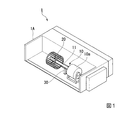
図1は、室内機1の内部における全体構成を示している。
図1に示す室内機1は、空調機(空気調和機)を構成する機材のうち室内に設置される室内機である。ここで、空調機は、室外に設置される室外機と、室内に設置される室内機1と、で構成される。図1に示すように、室内機1は、筐体1Aと、ファンモータ10と、ファン20と、容量形成部材30と、を備えている。
FIG. 1 shows an overall configuration inside the indoor unit 1.
The indoor unit 1 shown in FIG. 1 is an indoor unit installed indoors among the equipment which comprises an air conditioner (air conditioner). Here, the air conditioner includes an outdoor unit installed outside and an indoor unit 1 installed indoors. As shown in FIG. 1, the indoor unit 1 includes a housing 1 </ b> A, a
筐体1Aは、導電性を有する部材からなる室内機1の筐体である。筐体1Aは、アースに電気的に接続されており、全体が接地電位とされている。
ファンモータ10は、ファンモータ本体10aと、当該ファンモータ本体10aから伸びるシャフト11(軸部材)と、を有している。ファンモータ10は、例えば、DCブラシレスモータであって、PWM方式に基づく制御信号に応じてシャフト11を回転駆動させる。当該制御信号は、インバータ回路(図示せず)から入力される。
ファン20は、シャフト11を通じてファンモータ10に連結されることで、シャフト11の回転に伴い、回転する。ファン20が回転することで、室内機1から室内への送風がなされる。
容量形成部材30は、導体材料で形成され、一端が筐体1Aの内壁に取り付けられている。容量形成部材30は、筐体1Aと電気的に接続されることで筐体1Aと同電位(即ち、接地電位)とされる。
The
The
The
The
図2は、室内機1内部のうち、ファンモータ10、ファン20、及び、容量形成部材30の構造及び配置を示している。
図2に示すように、ファンモータ本体10aは、固定部材40a、40bにより、筐体1Aの内壁に固定設置されている。また、シャフト11は、ファンモータ本体10aから筐体1Aの内面に沿う方向に伸びており、その先端にはファン20が取り付けられている。ファンモータ本体10aに上述の制御信号が入力されることで、シャフト11及びファン20が回転軸線O回りに回転する。
また、図2に示すように、容量形成部材30は、ファンモータ本体10aとファン20との間の空間において筐体1Aに固定設置される。容量形成部材30は、基端(筐体1Aに固定されている側)からファンモータ10のシャフト11にかけて伸びるように形成された柱状部材30a、及び、柱状部材30aの先端に設けられシャフト11の側面と対向する面を有する対向部材30bと、を有してなる。
FIG. 2 shows the structure and arrangement of the
As shown in FIG. 2, the fan motor
Further, as shown in FIG. 2, the
次に、図3を参照しながら、容量形成部材30の構造、及び、シャフト11と容量形成部材30との位置関係をより詳細に説明する。
図3は、回転軸線Oに垂直な面方向における、シャフト11及び容量形成部材30の断面構造を示している。
図3に示すように、シャフト11は円柱状に形成されており、その断面は回転軸線Oを中心とする円状とされている。
また、容量形成部材30の対向部材30bは、回転軸線Oを中心とする半円状に形成され、シャフト11の円弧状の側面βと間隔をあけて対向する円弧状の対向面αを有する。
Next, the structure of the
FIG. 3 shows a cross-sectional structure of the
As shown in FIG. 3, the
Further, the facing
本実施形態において、ファンモータ本体10aとファン20との間隔(図2に示す距離d1)は、50mm程度とされる。そのため、対向部材30bの回転軸線O方向の長さ(図2に示す距離d2)は、この間隔(距離d1)に収まる程度の長さとして、例えば、30mm程度とされる。
また、図3において、シャフト11の外径r1は13mm程度とされ、対向部材30bの内径r2は15mm程度とされる。したがって、側面βと対向面αとの間隔Δd1は1mm程度とされる。
ここで、側面βと対向面αとの間は空気で満たされている。したがって、上述の構成により、シャフト11と容量形成部材30との間には、5.4pF程度の静電容量が形成される。
なお、上述の各寸法はあくまで一例であり、他の実施形態においては室内機1の内部構成等に応じて適宜変更可能である。
In the present embodiment, the distance between the fan motor
In FIG. 3, the outer diameter r1 of the
Here, the space between the side surface β and the facing surface α is filled with air. Therefore, with the above configuration, an electrostatic capacity of about 5.4 pF is formed between the
In addition, each above-mentioned dimension is an example to the last, and in other embodiment, it can change suitably according to the internal structure of the indoor unit 1, etc.
(ファンモータの内部構成)
図4は、第1の実施形態に係るファンモータの内部構成を示す図である。
図4は、ファンモータ10は、巻線Wが巻かれたステータ12と、ステータ12の内周面に沿って永久磁石Mを取付けたロータ13と、を備えている。ファンモータ10は、パワートランジスタ等のスイッチング素子のPWM制御によるスイッチング状態に応じて発生する回転磁界によってロータ13を回転させる。
(Internal configuration of fan motor)
FIG. 4 is a diagram illustrating an internal configuration of the fan motor according to the first embodiment.
4, the
また、ファンモータ10は、ファンモータ本体10aの内部におけるシャフト11延在方向奥側と手前側のそれぞれにおいて、当該シャフト11を回転可能に支持する2つの軸受14を備えている。2つの軸受14は、それぞれ、軸受内輪14aと、軸受外輪14bと、軸受ボール14cと、を有してなる。
軸受内輪14aは、シャフト11に固定され、ロータ13及びシャフト11と一体となって回転する。軸受内輪14aは、シャフト11と同電位とされる。
軸受外輪14bは、軸受内輪14aの外周に固定設置される。
軸受ボール14cは、軸受内輪14a及び軸受外輪14bの間に設けられる。
In addition, the
The bearing
The bearing
The bearing
また、ファンモータ10は、2つの軸受14をそれぞれ覆うように形成され、ファンモータ本体10aの外装をなす2つのブラケット15を備えている。2つのブラケット15は導体材料からなり、2つの軸受外輪14bの各々と接して同電位とされる。また、2つのブラケット15同士も電気的に接続されて同電位とされている。ただし、2つのブラケット15は、筐体1Aとは電気的に接続されておらず、接地されていない。
In addition, the
ファンモータ10の駆動に伴い、軸受外輪14b(ブラケット15)と、軸受内輪14a(シャフト11)との間に軸電圧Vshが生じる(図4を参照)。この軸電圧Vshが大きくなると、軸受ボール14c等に電食を生じさせ得る。
As the
(ファンモータ内部及び周辺の等価回路)
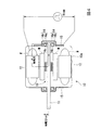
図5は、第1の実施形態に係るファンモータ内部及び周辺の、インバータのスイッチング制御に応じたコモンモードノイズに対する等価回路を示す図である。
また、図6は、第1の実施形態に係るファンモータの内部に生じる浮遊静電容量を示す図である。
また、図7は、第1の実施形態に係るファンモータと室内機筐体との間に生じる浮遊静電容量を示す図である。
図5に示す回路は、ファンモータ10を室内機1の筐体1Aに固定して組み込んだ場合におけるファンモータ10内部及び周辺についての等価回路である。また、図6に示すように、ファンモータ本体10aは、内部に、インバータ回路が実装された基板60を備えている。
以下、図5〜図7を参照しながら、本実施形態のファンモータ10に生じる軸電圧Vshについて説明する。
(Equivalent circuit inside and around the fan motor)
FIG. 5 is a diagram showing an equivalent circuit for common mode noise according to switching control of the inverter inside and around the fan motor according to the first embodiment.
FIG. 6 is a diagram illustrating stray capacitance generated inside the fan motor according to the first embodiment.
FIG. 7 is a diagram illustrating stray capacitance generated between the fan motor and the indoor unit housing according to the first embodiment.
The circuit shown in FIG. 5 is an equivalent circuit for the inside and the periphery of the
Hereinafter, the shaft voltage Vsh generated in the
図5において、“Vcom”は、コモンモードノイズの発生源を示している。また、“P”は、基板60に実装されたインバータ回路の正直流ラインを示し、“N”は、基板60に実装されたインバータ回路の負直流ラインを示している。ファンモータ10は、正直流ラインPと負直流ラインNとの間に生じる直流電圧を制御信号に基づいて交流に変換してシャフト11及びファン20を回転駆動させる。図5に示す“Vcom”によれば、コモンモードノイズは、ファンモータ10にとっての基準電位(負直流ラインN)と巻線中性点Yとの間に発生する。
In FIG. 5, “Vcom” indicates a source of common mode noise. “P” indicates a positive DC line of the inverter circuit mounted on the
図5において、“Cne”は、負直流ラインNと筐体1A(アース)との間に設けられた静電容量(Yコンデンサ)を示しており、“Cpe”は、正直流ラインPと筐体1A(アース)間との間に設けられた静電容量(Yコンデンサ)を示している。そして、“Cpn”は、正直流ラインPと負直流ラインNとの間に設けられた静電容量(平滑コンデンサ)を示している。
In FIG. 5, “Cne” indicates a capacitance (Y capacitor) provided between the negative DC line N and the
図5及び図6において、“Cs”は、巻線Wとステータ12との間に生じる浮遊静電容量を示し、“Cm”は、巻線Wと永久磁石Mとの間に生じる浮遊静電容量を示している。また、“Cg”は、ステータ12とロータ13との間に生じる浮遊静電容量を示し、“Cmg”は、永久磁石Mに生じる浮遊静電容量を示している。更に、“Cd”は、ロータ13に生じる浮遊静電容量を示している。浮遊静電容量Cs、Cm、Cg、Cd、Cmgを通じ、巻線中性点Yとシャフト11との間に生じている正味の浮遊静電容量を“Css”と表記する。
また、“Csn”は、シャフト11と負直流ラインNとの間に生じる浮遊静電容量を示している。更に、“Cb1”、“Cb2”は、2つのベアリング浮遊静電容量(軸受14における軸受内輪14aと軸受外輪14bとの間に生じる浮遊静電容量)を示しており、“Csb”は、巻線Wとブラケット15との間に生じる浮遊静電容量を示している。そして、“Cn”は、ブラケット15と負直流ラインNとの間に生じる浮遊静電容量を示している。
5 and 6, “Cs” indicates a stray electrostatic capacity generated between the winding W and the
“Csn” indicates a floating electrostatic capacitance generated between the
図5及び図7において、“Cbe”は、ブラケット15と筐体1A(アース)との間に生じる静電容量を示しており、“Cse”は、シャフト11と筐体1A(アース)との間に生じる静電容量を示している。
5 and 7, “Cbe” indicates a capacitance generated between the
(作用、効果)
以下、第1の実施形態に係る室内機1が有する作用及び効果について説明する。
(Function, effect)
Hereinafter, functions and effects of the indoor unit 1 according to the first embodiment will be described.
図5において、ノイズ発生源Vcomから所定のノイズ電圧が印加された際に、負直流ラインNとブラケット15との間に生じる電位差を“Vbn”、ブラケット15と巻線中性点Yとの間に生じる電位差を“Vbw”とする。また、ノイズ発生源Vcomから所定のノイズ電圧が印加された際に、負直流ラインNとシャフト11との間に生じる電位差を“Vsn”、シャフト11と巻線中性点Yとの間に生じる電位差を“Vsw”とする(図5参照)。
図5に示す等価回路のうちファンモータ10に対応する部分のみに着目すると、電位差Vbnに対する電位差Vbwの比と、電位差Vsnに対する電位差Vswの比と、が一致する場合には軸電圧Vshがゼロとなることが読み取れる。したがって、ファンモータ10は、このような等価回路を考慮し、電位差Vbnに対する電位差Vbwの比と、電位差Vsnに対する電位差Vswの比と、が概ね一致するように構成されている。換言すると、ファンモータ本体10aの内部構造においては、ブラケット−負直流ライン間に対する巻線中性点−ブラケット間の静電容量比(Csb/Cn)と、シャフト−直流ライン間に対する巻線中性点−シャフト間の静電容量比(Css/Csn)と、が概ね一致するように構成されている。
In FIG. 5, when a predetermined noise voltage is applied from the noise generation source Vcom, the potential difference generated between the negative DC line N and the
Focusing only on the portion corresponding to the
しかしながら、ファンモータ10が筐体1Aに取り付けられると、更に、ブラケット15と筐体1Aとの間、及び、シャフト11と筐体1Aとの間に、それぞれ、浮遊静電容量Cbe、Cseが生じる。
ここで、図7に示すように、ブラケット15と筐体1Aとの間は、導体材料からなる固定部材40a、40bをもって締結される。そうすると、ブラケット15と、筐体1Aと同電位の固定部材40a、40bとの距離が近接するため、浮遊静電容量Cbeが比較的大きくなる。他方、シャフト11と筐体1Aとは比較的間隔が大きいため、浮遊静電容量Cseは、浮遊静電容量Cbeと比較して小さくなる。そのため、ファンモータ10を筐体1Aに組み入れることで生じる浮遊静電容量Cseと、浮遊静電容量Cbeとの差異に起因して軸電圧Vshが生じ得る。
However, when the
Here, as shown in FIG. 7, the
そこで、第1の実施形態に係る室内機1は、導体材料で形成され、一端が室内機1の筐体1Aに取り付けられ、他端にファンモータ本体10aから伸びるシャフト11の表面(側面β)と間隔をあけて対向する対向面αを有する容量形成部材30を備える態様としている(図1〜図3参照)。
このようにすることで、シャフト11と筐体1Aとの間の浮遊静電容量Cseが大きくなるので、浮遊静電容量Cbeとバランスを取ることができ、結果として、軸電圧Vshを低減することができる。
即ち、第1の実施形態に係る室内機1によれば、導電性ブラシ、セラミックボール等を用いることなく、導体材料からなる容量形成部材30を取り付けるのみで軸電圧Vshを低減することができる。したがって、低コストに軸受の電食を抑制することができる。
Therefore, the indoor unit 1 according to the first embodiment is formed of a conductive material, one end is attached to the
By doing in this way, since the floating electrostatic capacitance Cse between the
That is, according to the indoor unit 1 according to the first embodiment, the axial voltage Vsh can be reduced only by attaching the
また、第1の実施形態に係る室内機1によれば、容量形成部材30の対向面αは、室内機1の筐体1Aとファンモータ10のブラケット15との間の浮遊静電容量Cbeと、筐体1Aとファンモータ10のシャフト11との間の浮遊静電容量Cseと、が一致するように形成されている。
このようにすることで、ファンモータ10単体では軸電圧Vshの発生が抑制されている場合において、当該ファンモータ10を筐体1Aに取り付けた後であっても、軸電圧Vshの発生を抑制することができる。
Further, according to the indoor unit 1 according to the first embodiment, the facing surface α of the
By doing so, in the case where the generation of the axial voltage Vsh is suppressed in the
なお、他の実施形態においては、浮遊静電容量Cbeと浮遊静電容量Cseとが必ずしも一致している必要はない。容量形成部材30を設けることで、少なくとも浮遊静電容量Cbeと浮遊静電容量Cseとの差異が低減さえしていれば、軸電圧Vshを低減させる効果を奏することができる。
In other embodiments, the floating capacitance Cbe and the floating capacitance Cse do not necessarily match. By providing the
また、他の実施形態においては、ファンモータ10は、単体で軸電圧Vshの発生が抑制されていないファンモータであってもよい。即ち、ファンモータ本体10aの内部構造において、電位差Vbn(図5)に対する電位差Vbw(図5)の比と、電位差Vsn(図5)に対する電位差Vsw(図5)の比と、が一致していないファンモータを用いてもよい。
この場合、容量形成部材30の対向面αは、ファンモータ10における巻線中性点−ブラケット間に対するブラケット−負直流ライン間の静電容量比(Csb/Cn)と、巻線中性点−シャフト間に対するシャフト−直流ライン間の静電容量比(Css/Csn)と、が一致するように形成され得る。
In another embodiment, the
In this case, the facing surface α of the
また、第1の実施形態に係る対向部材30b(容量形成部材30)の対向面αと、円柱状のシャフト11とは、回転軸線Oを中心とする同心円状に形成されている(図3参照)。
このようにすることで、シャフト11の側面βと対向面αとの間隔Δd1(図3)を一定とすることができ、シャフト11と筐体1Aとの間の浮遊静電容量を効率的に増加させることができる。
Further, the facing surface α of the facing
By doing in this way, the space | interval (DELTA) d1 (FIG. 3) of the side surface (beta) of the
また、第1の実施形態に係る対向部材30bの対向面αは、半円状に形成されている(図3参照)。
このようにすることで、ファンモータ10の取り付け作業を行う際に、シャフト11と容量形成部材30とが干渉しないため、取り付け作業の負担を軽減することができる。
Further, the facing surface α of the facing
In this way, when the
なお、他の実施形態においては、対向面αは半円状でなくともよい。例えば、対向面αは、シャフト11の側面βの周方向全体を囲むような円状に形成されていてもよい。
このようにすることで、シャフト11と筐体1Aとの間の浮遊静電容量を一層増加させることができる。
In other embodiments, the opposing surface α may not be semicircular. For example, the facing surface α may be formed in a circular shape so as to surround the entire circumferential direction of the side surface β of the
By doing in this way, the floating electrostatic capacitance between the
また、本実施形態において、シャフト11の側面βと対向面αとの間隔Δd1は、例えば、1mm程度とされているが、当該間隔Δd1は、シャフト11の回転駆動時における揺れの度合いを考慮して決定されるのが好ましい。即ち、シャフト11の回転駆動に伴う揺れの度合いによっては、シャフト11と容量形成部材30とが接触することが考えられる。したがって、間隔Δd1は、回転駆動時にシャフト11が容量形成部材30と接触しない距離を限度として可能な限り小さくするのが好ましい。
In the present embodiment, the interval Δd1 between the side surface β of the
<第2の実施形態>
次に、第2の実施形態に係る室内機について、図8〜図10を参照しながら説明する。
<Second Embodiment>
Next, an indoor unit according to the second embodiment will be described with reference to FIGS.
(室内機の内部構成)
図8〜図10は、第2の実施形態に係る室内機の内部構成を示す第1の図〜第3の図である。
(Internal configuration of indoor unit)
8 to 10 are first to third diagrams showing an internal configuration of the indoor unit according to the second embodiment.
図8は、室内機1内部のうち、ファンモータ10、ファン20、及び、容量形成部材30の構造及び配置を示している。
FIG. 8 shows the structure and arrangement of the
図8に示すように、第2の実施形態に係る室内機1は、第1の実施形態に係る室内機1と比較して大容量(大型)のものとされ、複数(3つ)のファン20を備えている。第2の実施形態に係るファンモータ10は、シャフト11を回転駆動させることで、全てのファン20を同一の回転軸線O回りに回転させる。
As shown in FIG. 8, the indoor unit 1 according to the second embodiment has a larger capacity (larger size) than the indoor unit 1 according to the first embodiment, and a plurality (three) of fans. 20 is provided. The
第2の実施形態に係る室内機1は、第1の実施形態の構成に加え、更に、シャフト連結部材71と、シャフト延長部材72(軸部材)と、を備えている。
シャフト連結部材71は、シャフト11の先端とシャフト延長部材72とを連結する部材である。本実施形態において、シャフト連結部材71は誘電体材料で形成される。
シャフト延長部材72は、シャフト連結部材71を介してシャフト11の延在方向に伸びて配される部材であって、複数のファン20を支持する。また、シャフト延長部材72は、シャフト11と一体となって回転することで、複数のファン20を同一の回転軸線O回りに回転させる。シャフト延長部材72は、導体材料からなる。
In addition to the configuration of the first embodiment, the indoor unit 1 according to the second embodiment further includes a
The
The
また、図8に示すように、第2の実施形態に係る容量形成部材30は、シャフト延長部材72が複数のファン20を支持しながら伸びた先端において筐体1Aに固定設置される。容量形成部材30は、基端(筐体1Aに固定されている側)からシャフト延長部材72にかけて伸びるように形成された柱状部材30a、及び、柱状部材30aの先端に設けられシャフト延長部材72の側面と対向する面を有する対向部材30bと、を有してなる。また、容量形成部材30は、シャフト延長部材72の軸受となる軸受部材31を有している。容量形成部材30のうち柱状部材30a及び対向部材30bは導体材料からなり、軸受部材31は誘電体材料からなる。
Further, as shown in FIG. 8, the
図9は、シャフト11、シャフト連結部材71及びシャフト延長部材72の断面構造を示している。
図9に示すように、シャフト連結部材71は、2つのはめ込み口71a、71bを有するように形成されている。一方のはめ込み口71aにはシャフト11の先端がはめ込まれる。また、他方のはめ込み口71bには、シャフト11の先端と対向する方向からシャフト延長部材72の先端がはめ込まれて固定される。そうすると、シャフト延長部材72は、シャフト11の先端とシャフト延長部材72との先端とが、ギャップgの間隔で対向する状態で固定される。これにより、シャフト11とシャフト延長部材72とは、容量Ceを介して電気的に結合(カップリング)される。
ここで、シャフト連結部材71は、誘電率が高い誘電体材料によって形成され、また、ギャップgは、比較的薄く形成される。このようにすることで、容量Ceが増加し、シャフト11とシャフト延長部材72との間のインピーダンスが低下する。そうすると、所定の周波数成分を有するコモンモードノイズに関しては、シャフト延長部材72とシャフト11とは、ほぼ同電位となり得る。したがって、シャフト延長部材72は、電気的にはシャフト11と同一と見なすことができる。
FIG. 9 shows a cross-sectional structure of the
As shown in FIG. 9, the
Here, the
次に、図10を参照しながら、容量形成部材30の構造、及び、シャフト延長部材72と容量形成部材30との位置関係をより詳細に説明する。
図10は、回転軸線Oに垂直な面方向における、シャフト延長部材72及び容量形成部材30の断面構造を示している。
図10に示すように、シャフト延長部材72は円柱状に形成されており、その断面は回転軸線Oを中心とする円状とされている。
また、容量形成部材30の対向部材30bは、回転軸線Oを中心とする半円状に形成され、シャフト11の円弧状の側面βと間隔をあけて対向する円弧状の対向面αを有する。
更に、軸受部材31は、シャフト延長部材72の先端付近においてその外側に、回転軸線Oを中心とする円状に形成される。軸受部材31は、柱状部材30aを通じて固定設置されることで、シャフト延長部材72の軸受として機能する。シャフト延長部材72の側面β’と対向部材30bの対向面αとは、軸受部材31を介して対向する。
Next, the structure of the
FIG. 10 shows a cross-sectional structure of the
As shown in FIG. 10, the
Further, the facing
Further, the bearing
本実施形態において、対向部材30bの回転軸線O方向の長さ(図8に示す距離d3)は、例えば、20mm程度とされる。
また、図10において、シャフト延長部材72の外径r3は7mm程度とされ、また、対向部材30bの内径r4は、11mm程度とされる。したがって、側面β’と対向面αとの間隔Δd2は2mm程度とされる。
ここで、側面β’と対向面αとの間は誘電体材料からなる軸受部材31が存在する。軸受部材31の比誘電率εが4とすると、上述の構成により、シャフト延長部材72と容量形成部材30との間には、3.89pF程度の静電容量が形成される。
なお、上述の各寸法はあくまで一例であり、他の実施形態においては室内機1の内部構成等に応じて適宜変更可能である。
In the present embodiment, the length of the opposing
In FIG. 10, the outer diameter r3 of the
Here, a bearing
In addition, each above-mentioned dimension is an example to the last, and in other embodiment, it can change suitably according to the internal structure of the indoor unit 1, etc.
(作用、効果)
以上のとおり、第2の実施形態に係る室内機1によれば、容量形成部材30の対向面αとシャフト延長部材72の側面β’との間に誘電体材料(軸受部材31)が配されている。
このようにすることで、シャフト延長部材72と筐体1Aとの間の浮遊静電容量を効率的に増加させることができる。
(Function, effect)
As described above, according to the indoor unit 1 according to the second embodiment, the dielectric material (bearing member 31) is disposed between the facing surface α of the
By doing in this way, the floating electrostatic capacitance between the
また、第2の実施形態に係る室内機1によれば、誘電体材料(軸受部材31)は、シャフト延長部材72の外側に、回転軸線Oを中心とする円状に形成され、当該シャフト延長部材72を周方向に囲うように形成されている。
このようにすることで、容量形成部材30は、シャフト延長部材72と筐体1Aとの間の浮遊静電容量を増加させるだけでなく、シャフト延長部材72の軸受として機能する。これにより、シャフト延長部材72の回転軸の揺れを抑制することができる。
Further, according to the indoor unit 1 according to the second embodiment, the dielectric material (bearing member 31) is formed outside the
Thus, the
また、第2の実施形態に係る室内機1に係る軸部材は、ファンモータ10のシャフト11と、当該シャフト11の先端から、その延在方向に更に伸びるように配置されたシャフト延長部材72と、シャフト11とシャフト延長部材72とを連結するシャフト連結部材71と、を有してなる。
このようにすることで、シャフト延長部材72によりシャフト11を延長して複数のファン20を一度に回転させることができる。
Further, the shaft member according to the indoor unit 1 according to the second embodiment includes a
By doing in this way, the
また、第2の実施形態に係る室内機1によれば、シャフト連結部材71は誘電体材料からなり、シャフト11の先端とシャフト延長部材72の先端との間にギャップgが設けられている(図9参照)。即ち、上述のシャフト11とシャフト延長部材72とは、シャフト連結部材71を介して容量結合(カップリング)されている。
このようにすることで、シャフト11とシャフト延長部材72との間に生じる容量Ceが増加する。そうすると、シャフト延長部材72とシャフト11とは、ほぼ同電位となるため、シャフト延長部材72と筐体1Aとの間に容量を形成することによっても、軸電圧Vshを低減することができる。
Further, according to the indoor unit 1 according to the second embodiment, the
By doing in this way, the capacity | capacitance Ce produced between the
以上、第1、第2の実施形態に係る室内機1について詳細に説明したが、室内機1の具体的な態様は、上述のものに限定されることはなく、要旨を逸脱しない範囲内において種々の設計変更等を加えることは可能である。 As mentioned above, although the indoor unit 1 which concerns on 1st, 2nd embodiment was demonstrated in detail, the specific aspect of the indoor unit 1 is not limited to the above-mentioned thing, In the range which does not deviate from a summary. Various design changes and the like can be added.
第2の実施形態において、シャフト連結部材71は、誘電体材料からなるものとして説明したが、他の実施形態においてはこの態様に限定されず、例えば、シャフト連結部材71は、導体材料からなるものであってもよい。このようにしても、シャフト延長部材72とシャフト11とを同電位とすることは可能である。
In the second embodiment, the
また、第1、第2の実施形態において、ファンモータ10は、ファンモータ本体10aから一方にのみ伸びる単一のシャフト11を有する態様として説明したが、他の実施形態においてはこの態様に限定されない。
例えば、ファンモータ10は、ファンモータ本体10aを貫くように両方向に伸びる両軸のファンモータであってもよい。
In the first and second embodiments, the
For example, the
以上、本発明のいくつかの実施形態を説明したが、上述の各実施形態は、例として提示したものであり、発明の範囲を限定することは意図していない。上述の各実施形態は、その他の様々な形態で実施されることが可能であり、発明の要旨を逸脱しない範囲で種々の省略、置き換え、変更を行うことができる。上述の各実施形態及びその変形は、発明の範囲や要旨に含まれると同様に、特許請求の範囲に記載された発明とその均等の範囲に含まれるものとする。 As mentioned above, although several embodiment of this invention was described, each above-mentioned embodiment was shown as an example and is not intending limiting the range of invention. Each of the above-described embodiments can be implemented in various other forms, and various omissions, replacements, and changes can be made without departing from the scope of the invention. Each of the above-described embodiments and modifications thereof are included in the invention described in the claims and equivalents thereof, as long as they are included in the scope and gist of the invention.
1 室内機
1A 筐体
10 ファンモータ
10a ファンモータ本体
11 シャフト(軸部材)
12 ステータ
13 ロータ
14 軸受
14a 軸受内輪
14b 軸受外輪
14c 軸受ボール
15 ブラケット
20 ファン
30 容量形成部材
30a 柱状部材
30b 対向部材
31 軸受部材
40a、40b 固定部材
60 基板
71 シャフト連結部材
72 シャフト延長部材(軸部材)
M 永久磁石
W 巻線
DESCRIPTION OF SYMBOLS 1
12
M Permanent magnet W Winding
Claims (10)
前記筐体に取り付けられたファンモータと、
導体材料で形成され、一端が前記筐体に取り付けられ、他端に前記ファンモータの本体から伸びる軸部材の表面と間隔をあけて対向する対向面を有する容量形成部材と、
を備える室内機。 A grounded housing;
A fan motor attached to the housing;
A capacitor forming member formed of a conductive material, having one end attached to the housing and the other end facing the surface of the shaft member extending from the fan motor main body at an interval,
An indoor unit equipped with.
請求項1に記載の室内機。 In the facing surface of the capacity forming member, an electrostatic capacity between the housing and the bracket of the fan motor matches an electrostatic capacity between the housing and the shaft member of the fan motor. The indoor unit according to claim 1, wherein the indoor unit is formed as follows.
請求項1又は請求項2に記載の室内機。 The facing surface of the capacity forming member is formed by the electrostatic capacity ratio between the bracket and the negative DC line with respect to between the winding neutral point and the bracket in the fan motor, and the shaft member and direct current between the winding neutral point and the shaft member. The indoor unit according to claim 1, wherein the indoor unit is formed so that a capacitance ratio between the lines matches.
請求項1から請求項3の何れか一項に記載の室内機。 The indoor unit according to any one of claims 1 to 3, wherein the facing surface of the capacity forming member and the shaft member of the fan motor are formed concentrically around a rotation axis. .
請求項1から請求項4の何れか一項に記載の室内機。 The indoor unit according to any one of claims 1 to 4, wherein a dielectric material is disposed between the facing surface of the capacity forming member and a surface of the shaft member.
請求項5に記載の室内機。 The indoor unit according to claim 5, wherein the dielectric material is formed so as to surround the shaft member in a circumferential direction.
前記ファンモータのシャフトと、
当該シャフトの先端から、その延在方向に更に伸びるように配置されたシャフト延長部材と、
前記シャフトと前記シャフト延長部材とを連結するシャフト連結部材と、
を有する
請求項1から請求項6の何れか一項に記載の室内機。 The shaft member is
A shaft of the fan motor;
A shaft extension member arranged to extend further in the extending direction from the tip of the shaft;
A shaft connecting member that connects the shaft and the shaft extension member;
The indoor unit according to any one of claims 1 to 6.
請求項7に記載の室内機。 The indoor unit according to claim 7, wherein the shaft and the shaft extension member are capacitively coupled via the shaft connecting member.
室外機と、
を備える空調機。 The indoor unit according to any one of claims 1 to 8,
Outdoor unit,
Air conditioner equipped with.
導体材料で形成された容量形成部材の一端を前記筐体に取り付けて、他端に設けられた対向面を前記ファンモータの本体から伸びる軸部材の表面と間隔をあけて対向するように配置する工程と、
を有する室内機の製造方法。 Attaching a fan motor to the grounded indoor unit housing;
One end of a capacity forming member made of a conductive material is attached to the housing, and the opposing surface provided at the other end is arranged to face the surface of the shaft member extending from the main body of the fan motor with a gap. Process,
A method for manufacturing an indoor unit.
Priority Applications (5)
| Application Number | Priority Date | Filing Date | Title |
|---|---|---|---|
| JP2016055309A JP2017169425A (en) | 2016-03-18 | 2016-03-18 | Indoor unit, air conditioner, and method of manufacturing indoor unit |
| AU2017233348A AU2017233348A1 (en) | 2016-03-18 | 2017-02-03 | Indoor unit, air conditioner, and method for manufacturing indoor unit |
| EP17766112.1A EP3386078A4 (en) | 2016-03-18 | 2017-02-03 | Indoor unit, air conditioner, and method for manufacturing indoor unit |
| PCT/JP2017/003970 WO2017159104A1 (en) | 2016-03-18 | 2017-02-03 | Indoor unit, air conditioner, and method for manufacturing indoor unit |
| CN201780005376.3A CN108521842A (en) | 2016-03-18 | 2017-02-03 | The manufacturing method of indoor unit, air conditioner and indoor unit |
Applications Claiming Priority (1)
| Application Number | Priority Date | Filing Date | Title |
|---|---|---|---|
| JP2016055309A JP2017169425A (en) | 2016-03-18 | 2016-03-18 | Indoor unit, air conditioner, and method of manufacturing indoor unit |
Publications (2)
| Publication Number | Publication Date |
|---|---|
| JP2017169425A true JP2017169425A (en) | 2017-09-21 |
| JP2017169425A5 JP2017169425A5 (en) | 2019-02-21 |
Family
ID=59852212
Family Applications (1)
| Application Number | Title | Priority Date | Filing Date |
|---|---|---|---|
| JP2016055309A Pending JP2017169425A (en) | 2016-03-18 | 2016-03-18 | Indoor unit, air conditioner, and method of manufacturing indoor unit |
Country Status (5)
| Country | Link |
|---|---|
| EP (1) | EP3386078A4 (en) |
| JP (1) | JP2017169425A (en) |
| CN (1) | CN108521842A (en) |
| AU (1) | AU2017233348A1 (en) |
| WO (1) | WO2017159104A1 (en) |
Cited By (1)
| Publication number | Priority date | Publication date | Assignee | Title |
|---|---|---|---|---|
| JP2022534391A (en) * | 2019-07-26 | 2022-07-29 | グアンドン ウェリング モーター マニュファクチュアリング カンパニー リミテッド | Motors and electrical equipment having such motors |
Citations (9)
| Publication number | Priority date | Publication date | Assignee | Title |
|---|---|---|---|---|
| JPS58183070U (en) * | 1982-05-28 | 1983-12-06 | 芝浦メカトロニクス株式会社 | Axial current prevention device |
| JP3068821B1 (en) * | 1999-03-19 | 2000-07-24 | 松下精工株式会社 | Bearing current reduction device for rotating machine |
| JP2003032944A (en) * | 2001-07-11 | 2003-01-31 | Murata Mach Ltd | Electric motor and driven device there with |
| JP2003199285A (en) * | 2001-12-26 | 2003-07-11 | Meidensha Corp | Inverter driving induction motor |
| WO2009001546A1 (en) * | 2007-06-25 | 2008-12-31 | Panasonic Corporation | Electric motor, and electric device having the motor |
| JP2012191734A (en) * | 2011-03-10 | 2012-10-04 | Daikin Ind Ltd | Motor |
| WO2012147244A1 (en) * | 2011-04-27 | 2012-11-01 | パナソニック株式会社 | Electric motor and electric device provided with same |
| JP2012228137A (en) * | 2011-04-22 | 2012-11-15 | Daikin Ind Ltd | Bearing discharge prevention mechanism and motor unit |
| JP2014176111A (en) * | 2013-03-06 | 2014-09-22 | Daikin Ind Ltd | Motor |
Family Cites Families (2)
| Publication number | Priority date | Publication date | Assignee | Title |
|---|---|---|---|---|
| CN102474152A (en) * | 2009-10-09 | 2012-05-23 | 松下电器产业株式会社 | Air conditioner |
| JP5656795B2 (en) * | 2011-10-14 | 2015-01-21 | 三菱電機株式会社 | Air conditioner |
-
2016
- 2016-03-18 JP JP2016055309A patent/JP2017169425A/en active Pending
-
2017
- 2017-02-03 CN CN201780005376.3A patent/CN108521842A/en active Pending
- 2017-02-03 WO PCT/JP2017/003970 patent/WO2017159104A1/en active Application Filing
- 2017-02-03 EP EP17766112.1A patent/EP3386078A4/en not_active Withdrawn
- 2017-02-03 AU AU2017233348A patent/AU2017233348A1/en not_active Abandoned
Patent Citations (9)
| Publication number | Priority date | Publication date | Assignee | Title |
|---|---|---|---|---|
| JPS58183070U (en) * | 1982-05-28 | 1983-12-06 | 芝浦メカトロニクス株式会社 | Axial current prevention device |
| JP3068821B1 (en) * | 1999-03-19 | 2000-07-24 | 松下精工株式会社 | Bearing current reduction device for rotating machine |
| JP2003032944A (en) * | 2001-07-11 | 2003-01-31 | Murata Mach Ltd | Electric motor and driven device there with |
| JP2003199285A (en) * | 2001-12-26 | 2003-07-11 | Meidensha Corp | Inverter driving induction motor |
| WO2009001546A1 (en) * | 2007-06-25 | 2008-12-31 | Panasonic Corporation | Electric motor, and electric device having the motor |
| JP2012191734A (en) * | 2011-03-10 | 2012-10-04 | Daikin Ind Ltd | Motor |
| JP2012228137A (en) * | 2011-04-22 | 2012-11-15 | Daikin Ind Ltd | Bearing discharge prevention mechanism and motor unit |
| WO2012147244A1 (en) * | 2011-04-27 | 2012-11-01 | パナソニック株式会社 | Electric motor and electric device provided with same |
| JP2014176111A (en) * | 2013-03-06 | 2014-09-22 | Daikin Ind Ltd | Motor |
Cited By (2)
| Publication number | Priority date | Publication date | Assignee | Title |
|---|---|---|---|---|
| JP2022534391A (en) * | 2019-07-26 | 2022-07-29 | グアンドン ウェリング モーター マニュファクチュアリング カンパニー リミテッド | Motors and electrical equipment having such motors |
| JP7288983B2 (en) | 2019-07-26 | 2023-06-08 | グアンドン ウェリング モーター マニュファクチュアリング カンパニー リミテッド | Motors and electrical equipment having such motors |
Also Published As
| Publication number | Publication date |
|---|---|
| EP3386078A4 (en) | 2019-01-02 |
| CN108521842A (en) | 2018-09-11 |
| AU2017233348A1 (en) | 2018-07-19 |
| WO2017159104A1 (en) | 2017-09-21 |
| EP3386078A1 (en) | 2018-10-10 |
Similar Documents
| Publication | Publication Date | Title |
|---|---|---|
| JP5338641B2 (en) | Electric motor and electric device including the same | |
| JP4957874B2 (en) | Electric motor and electric device including the same | |
| JP4935934B2 (en) | Electric motor and electric device including the same | |
| JP5112574B2 (en) | Electric motor and electric device including the same | |
| EP2728720A2 (en) | DC brushless motor with external rotor | |
| WO2011141957A1 (en) | Electric motor and electric device including the same | |
| WO2014174826A1 (en) | Electric motor and electric apparatus equipped with electric motor | |
| JP2013066253A (en) | Motor and electrical apparatus provided with the same | |
| JP5370431B2 (en) | Electric motor and electric device including the same | |
| JP5397466B2 (en) | Electric motor and electric device including the same | |
| WO2011043075A1 (en) | Air conditioner | |
| CN103339837A (en) | Molded motor | |
| JP2014107998A (en) | Motor | |
| JP2017169425A (en) | Indoor unit, air conditioner, and method of manufacturing indoor unit | |
| WO2017068861A1 (en) | Indoor unit, air conditioner provided with indoor unit, and method for assembling indoor unit | |
| JP5656795B2 (en) | Air conditioner | |
| JP2011205724A (en) | Air conditioner | |
| JP2012239368A (en) | Motor and electric apparatus using the same | |
| US11777362B2 (en) | Motor and electric apparatus including the same | |
| JP6383949B2 (en) | Electric motor and electric device including the same | |
| JP2013066252A (en) | Motor and electrical apparatus provided with the same | |
| JP2014147241A (en) | Motor and electric apparatus including the same | |
| JP5493931B2 (en) | Air conditioner | |
| JP2015056970A (en) | Electric apparatus | |
| CN115694035A (en) | Motor and electric device provided with same |
Legal Events
| Date | Code | Title | Description |
|---|---|---|---|
| A521 | Request for written amendment filed |
Free format text: JAPANESE INTERMEDIATE CODE: A821 Effective date: 20160322 |
|
| A711 | Notification of change in applicant |
Free format text: JAPANESE INTERMEDIATE CODE: A712 Effective date: 20170615 |
|
| A521 | Request for written amendment filed |
Free format text: JAPANESE INTERMEDIATE CODE: A821 Effective date: 20170616 |
|
| RD03 | Notification of appointment of power of attorney |
Free format text: JAPANESE INTERMEDIATE CODE: A7423 Effective date: 20181109 |
|
| A521 | Request for written amendment filed |
Free format text: JAPANESE INTERMEDIATE CODE: A523 Effective date: 20190108 |
|
| A621 | Written request for application examination |
Free format text: JAPANESE INTERMEDIATE CODE: A621 Effective date: 20190108 |
|
| A131 | Notification of reasons for refusal |
Free format text: JAPANESE INTERMEDIATE CODE: A131 Effective date: 20200114 |
|
| A02 | Decision of refusal |
Free format text: JAPANESE INTERMEDIATE CODE: A02 Effective date: 20200811 |