JP2017168423A - Plug unit and receptacle unit - Google Patents
Plug unit and receptacle unit Download PDFInfo
- Publication number
- JP2017168423A JP2017168423A JP2016198738A JP2016198738A JP2017168423A JP 2017168423 A JP2017168423 A JP 2017168423A JP 2016198738 A JP2016198738 A JP 2016198738A JP 2016198738 A JP2016198738 A JP 2016198738A JP 2017168423 A JP2017168423 A JP 2017168423A
- Authority
- JP
- Japan
- Prior art keywords
- connector
- plug
- receptacle
- predetermined standard
- connectors
- Prior art date
- Legal status (The legal status is an assumption and is not a legal conclusion. Google has not performed a legal analysis and makes no representation as to the accuracy of the status listed.)
- Granted
Links
- 239000012212 insulator Substances 0.000 claims abstract description 11
- 238000003032 molecular docking Methods 0.000 claims description 165
- 239000000758 substrate Substances 0.000 claims description 44
- 238000003780 insertion Methods 0.000 claims description 37
- 230000037431 insertion Effects 0.000 claims description 37
- 239000002184 metal Substances 0.000 claims description 14
- 229910052751 metal Inorganic materials 0.000 claims description 14
- 230000002093 peripheral effect Effects 0.000 claims description 11
- 230000002441 reversible effect Effects 0.000 claims description 5
- 239000011347 resin Substances 0.000 claims description 3
- 229920005989 resin Polymers 0.000 claims description 3
- 238000005549 size reduction Methods 0.000 abstract 1
- 238000005476 soldering Methods 0.000 description 8
- 230000013011 mating Effects 0.000 description 5
- 239000000853 adhesive Substances 0.000 description 2
- 230000001070 adhesive effect Effects 0.000 description 2
- 230000005540 biological transmission Effects 0.000 description 2
- 238000010586 diagram Methods 0.000 description 2
- 239000000463 material Substances 0.000 description 2
- 238000006073 displacement reaction Methods 0.000 description 1
- 150000002739 metals Chemical class 0.000 description 1
- 238000000034 method Methods 0.000 description 1
Images


Abstract
Description
本発明は、複数の所定規格プラグコネクタを備えたプラグユニット及び複数の所定規格レセプタクルコネクタを備えたレセプタクルユニットに関するものである。 The present invention relates to a plug unit including a plurality of predetermined standard plug connectors and a receptacle unit including a plurality of predetermined standard receptacle connectors.
タブレット型PC等の携帯端末装置においては、キーボードやマウス等の周辺機器をドッキングさせて使用するケースが増えている。このような場合においては、高速伝送を実現させるべく、より多くのコンタクトを備えたドッキングコネクタを携帯端末装置及び周辺機器に搭載することが求められている。例えば特許文献1には、多数のコンタクトが配列されている一対のコネクタを有し、一方のコネクタを他方のコネクタにドッキングさせるドッキングコネクタについて記載されている。 In portable terminal devices such as tablet PCs, there are an increasing number of cases where peripheral devices such as a keyboard and a mouse are docked. In such a case, in order to realize high-speed transmission, it is required to mount a docking connector having more contacts on the mobile terminal device and peripheral devices. For example, Patent Document 1 describes a docking connector that has a pair of connectors in which a large number of contacts are arranged, and docks one connector to the other connector.
ところで、特許文献1記載のドッキングコネクタにおいて、一方のコネクタは、他方のコネクタとのみドッキング可能である。即ち、一方のコネクタを搭載した周辺機器を、他方のコネクタを搭載した携帯端末装置にドッキングさせることは可能であるが、他方のコネクタ以外のコネクタを搭載した周辺機器をドッキングさせることはできない。 By the way, in the docking connector of patent document 1, one connector can be docked only with the other connector. That is, a peripheral device equipped with one connector can be docked to a portable terminal device equipped with the other connector, but a peripheral device equipped with a connector other than the other connector cannot be docked.
そこで、USB Type C等の標準規格準拠のコネクタ(以下、所定規格コネクタという。)を2つ以上備えたドッキングコネクタを使用することが検討されている。例えば携帯端末装置に2つの所定規格レセプタクルコネクタを備えたレセプタクルユニットとしてのレセプタクル側ドッキングコネクタを搭載した場合、2つの所定規格プラグコネクタを備えたプラグユニットとしてのプラグ側ドッキングコネクタを搭載した周辺機器とドッキング可能なだけでなく、1つの所定規格プラグコネクタを搭載した周辺機器とドッキングさせることもできる。即ち、携帯端末装置側のレセプタクル側ドッキングコネクタが備える2つの所定規格レセプタクルコネクタのうちの一方を1つの所定規格プラグコネクタを搭載した周辺機器にドッキングさせることができる。更には、上記レセプタクル側ドッキングコネクタが備える2つの所定規格レセプタクルコネクタのうちの他方を、1つの所定規格プラグコネクタを搭載した他の周辺機器に接続させることも可能となる。 Therefore, it is considered to use a docking connector provided with two or more connectors conforming to a standard such as USB Type C (hereinafter referred to as a predetermined standard connector). For example, in the case where a receptacle-side docking connector as a receptacle unit having two predetermined standard receptacle connectors is mounted on a portable terminal device, a peripheral device having a plug-side docking connector as a plug unit having two predetermined standard plug connectors; Not only can it be docked, it can also be docked with a peripheral device equipped with one predetermined standard plug connector. In other words, one of the two predetermined standard receptacle connectors provided in the receptacle-side docking connector on the mobile terminal device side can be docked with a peripheral device equipped with one predetermined standard plug connector. Furthermore, the other of the two predetermined standard receptacle connectors provided in the receptacle-side docking connector can be connected to another peripheral device equipped with one predetermined standard plug connector.
しかしながら、上述のようなドッキングコネクタを組み立てる工程において、2つの所定規格コネクタを正確な位置に且つ正確な姿勢で実装するのは困難であった。実装時における2つの所定規格コネクタの位置及び姿勢にずれが生じると、所定規格コネクタが相手コネクタと接続する際に接続不良を生じるおそれや、所定規格コネクタが相手コネクタと嵌合する際に破損するおそれがあった。 However, in the process of assembling the docking connector as described above, it has been difficult to mount the two predetermined standard connectors at an accurate position and in an accurate posture. If the position and posture of the two predetermined standard connectors at the time of mounting are shifted, the predetermined standard connector may cause a connection failure when connecting to the mating connector, or the predetermined standard connector may be damaged when mated with the mating connector. There was a fear.
また、コンタクトを増やすことにより更なる高速伝送を実現させるために、上述のような2つ以上の所定規格コネクタを備えたドッキングコネクタに、追加のコネクタを搭載することが求められている。しかしながら、追加のコネクタを搭載した場合、ドッキングコネクタのサイズが大型化するという問題があった。 Further, in order to realize further high-speed transmission by increasing the number of contacts, it is required to mount an additional connector on the docking connector having two or more predetermined standard connectors as described above. However, when an additional connector is mounted, there is a problem that the size of the docking connector increases.
本発明の目的は、公差を最小限に抑えることができ、小型化を図ることができるプラグユニット及びレセプタクルユニットを提供することである。 An object of the present invention is to provide a plug unit and a receptacle unit that can minimize tolerances and can be miniaturized.
本発明のプラグユニットは、複数の所定規格プラグコネクタを備えたプラグユニットであって、前記所定規格プラグコネクタは、所定規格レセプタクルコネクタの接続端子と接続するコンタクトを備え、前記複数の所定規格プラグコネクタそれぞれが有する前記コンタクトを保持すると共に、前記複数の所定規格プラグコネクタそれぞれの間隔及び前記所定規格プラグコネクタの姿勢を規定する1つの絶縁体を備えることを特徴とする。 The plug unit of the present invention is a plug unit including a plurality of predetermined standard plug connectors, wherein the predetermined standard plug connector includes a contact connected to a connection terminal of a predetermined standard receptacle connector, and the plurality of predetermined standard plug connectors. Each of the plurality of predetermined standard plug connectors includes a single insulator that holds the contacts and defines the interval between the predetermined standard plug connectors and the attitude of the predetermined standard plug connector.
また、本発明のプラグユニットは、複数の前記所定規格レセプタクルコネクタを備えたレセプタクルユニットとドッキングする際、前記所定規格プラグコネクタが前記所定規格レセプタクルコネクタと嵌合する前に、前記レセプタクルユニットのガイド挿入部に挿入されるガイド部を備えることを特徴とする。 In addition, when the plug unit of the present invention is docked with a receptacle unit including a plurality of the predetermined standard receptacle connectors, the guide unit of the receptacle unit is inserted before the predetermined standard plug connector is fitted to the predetermined standard receptacle connector. It is characterized by comprising a guide part inserted into the part.
また、本発明のプラグユニットは、前記ガイド部が第1追加コネクタを備えることを特徴とする。 The plug unit of the present invention is characterized in that the guide portion includes a first additional connector.
また、本発明のプラグユニットは、複数の所定規格プラグコネクタと、前記複数の所定規格プラグコネクタを覆うカバーとを備えたプラグユニットであって、複数の所定規格レセプタクルコネクタを備えたレセプタクルユニットとドッキングする際、前記所定規格プラグコネクタが前記プラグユニットと嵌合する前に、前記レセプタクルユニットのガイド挿入部に挿入されるガイド部を備え、前記ガイド部は、前記カバーと一体に形成されていることを特徴とする。 The plug unit of the present invention is a plug unit including a plurality of predetermined standard plug connectors and a cover covering the plurality of predetermined standard plug connectors, and the receptacle unit including the plurality of predetermined standard receptacle connectors and the docking unit. When the predetermined standard plug connector is fitted with the plug unit, the guide unit is provided with a guide portion that is inserted into the guide insertion portion of the receptacle unit, and the guide portion is formed integrally with the cover. It is characterized by.
また、本発明のプラグユニットは、前記カバーが前記所定規格プラグコネクタの前記所定規格レセプタクルコネクタと嵌合する嵌合部を露出させるための開口部を有しており、前記所定規格プラグコネクタの外壁部と前記開口部を形成する壁部との間には、前記所定規格レセプタクルコネクタと嵌合する嵌合方向と交差する交差平面において前記所定規格プラグコネクタが移動できるように、所定のスペースが形成されており、前記開口部に対する少なくとも1つの前記所定規格プラグコネクタの位置及び姿勢の少なくとも一方を制御する制御部を備えることを特徴とする。 Further, the plug unit of the present invention has an opening for exposing a fitting portion for fitting the cover to the predetermined standard receptacle connector of the predetermined standard plug connector, and an outer wall of the predetermined standard plug connector. A predetermined space is formed between the wall portion and the wall portion forming the opening so that the predetermined standard plug connector can move in an intersecting plane intersecting a fitting direction in which the predetermined standard receptacle connector is fitted. And a control unit that controls at least one of a position and a posture of at least one predetermined standard plug connector with respect to the opening.
また、本発明のプラグユニットは、前記ガイド部及び前記カバーが樹脂により形成されており、前記ガイド部には、金属が組み込まれていることを特徴とする。 In the plug unit of the present invention, the guide part and the cover are made of resin, and metal is incorporated in the guide part.
また、本発明のプラグユニットは、前記ガイド部に配置される第1追加コネクタを備えることを特徴とする。 In addition, the plug unit of the present invention includes a first additional connector disposed in the guide portion.
また、本発明のプラグユニットは、複数の所定規格プラグコネクタを備えたプラグユニットであって、複数の所定規格レセプタクルコネクタを備えたレセプタクルユニットとドッキングする際、前記所定規格プラグコネクタが前記所定規格レセプタクルコネクタと嵌合する前に、前記レセプタクルユニットのガイド挿入部に挿入されるガイド部と、前記ガイド部に配置される第1追加コネクタとを備えることを特徴とする。 The plug unit of the present invention is a plug unit having a plurality of predetermined standard plug connectors, and when the docking unit is docked with a receptacle unit having a plurality of predetermined standard receptacle connectors, the predetermined standard plug connector is the predetermined standard receptacle. Prior to mating with a connector, the receptacle unit includes a guide portion that is inserted into a guide insertion portion of the receptacle unit, and a first additional connector that is disposed in the guide portion.
また、本発明のプラグユニットは、前記所定規格プラグコネクタが前記所定規格レセプタクルコネクタの接続端子と接続するコンタクトを備え、複数の前記所定規格プラグコネクタのそれぞれが有する前記コンタクトを保持すると共に、複数の前記所定規格プラグコネクタそれぞれの間隔及び前記所定規格プラグコネクタの姿勢を規定する1つの絶縁体を備えることを特徴とする。 Further, the plug unit of the present invention includes a contact for connecting the predetermined standard plug connector to a connection terminal of the predetermined standard receptacle connector, holds the contact of each of the plurality of predetermined standard plug connectors, and a plurality of One insulator is provided that defines the interval between the predetermined standard plug connectors and the posture of the predetermined standard plug connector.
また、本発明のプラグユニットは、前記ガイド部が前記所定規格プラグコネクタの周辺部に形成されることを特徴とする。 Further, the plug unit of the present invention is characterized in that the guide portion is formed in a peripheral portion of the predetermined standard plug connector.
また、本発明のプラグユニットは、前記ガイド部が前記複数の所定規格プラグコネクタの間に形成されることを特徴とする。 The plug unit of the present invention is characterized in that the guide portion is formed between the plurality of predetermined standard plug connectors.
また、本発明のプラグユニットは、前記ガイド部が金属により形成されることを特徴とする。 Further, the plug unit of the present invention is characterized in that the guide portion is made of metal.
また、本発明のプラグユニットは、前記複数の所定規格プラグコネクタそれぞれを配列する配列方向に直交する方向の前記ガイド部の幅が前記配列方向に直交する方向の前記所定規格レセプタクルコネクタの内径の内径幅以上であることを特徴とする。 In the plug unit of the present invention, the inner diameter of the inner diameter of the predetermined standard receptacle connector in a direction in which the width of the guide portion in the direction orthogonal to the arrangement direction in which each of the plurality of predetermined standard plug connectors is arranged is orthogonal to the arrangement direction It is more than width.
また、本発明のプラグユニットは、前記ガイド部が前記第1追加コネクタを配置する配置部を有することを特徴とする。 The plug unit of the present invention is characterized in that the guide portion has an arrangement portion for arranging the first additional connector.
また、本発明のプラグユニットは、前記第1追加コネクタが第2追加コネクタの接続端子と接続する接続面を有する第1コンタクトを備え、前記第1コンタクトの前記接続面は、前記ガイド部の表面に配置されることを特徴とする。 The plug unit of the present invention further includes a first contact having a connection surface for connecting the first additional connector to a connection terminal of the second additional connector, and the connection surface of the first contact is a surface of the guide portion. It is characterized by being arranged in.
また、本発明のプラグユニットは、複数の前記所定規格プラグコネクタがリバーシブルコネクタであることを特徴とする。 In the plug unit of the present invention, the plurality of predetermined standard plug connectors are reversible connectors.
また、本発明のプラグユニットは、少なくとも2つの前記第1追加コネクタを備え、前記レセプタクルユニットは、一方の前記第1追加コネクタ及び他方の前記第1追加コネクタと接続可能な少なくとも1つの前記第2追加コネクタを備えることを特徴とする。 The plug unit of the present invention includes at least two first additional connectors, and the receptacle unit can be connected to one of the first additional connectors and the other first additional connector. An additional connector is provided.
また、本発明のプラグユニットは、前記所定規格プラグコネクタがUSB Type Cであることを特徴とする。 The plug unit of the present invention is characterized in that the predetermined standard plug connector is USB Type C.
また、本発明のレセプタクルユニットは、複数の所定規格レセプタクルコネクタを備え、電子機器に搭載されるレセプタクルユニットコネクタであって、複数の所定規格プラグコネクタを備えたプラグユニットとドッキングする際、前記所定規格レセプタクルコネクタが前記所定規格プラグコネクタと嵌合する前に、前記プラグユニットのガイド部を受け入れる少なくとも1つのガイド受入部を備え、前記複数の所定規格レセプタクルコネクタのうちの少なくとも1つの前記所定規格レセプタクルコネクタは、他の少なくとも1つの前記所定規格レセプタクルコネクタとは別に基板に実装されており、少なくとも2つの前記ガイド受入部を備える場合、前記少なくとも2つの前記ガイド受入部は、一体に形成されており、前記ガイド受入部は、前記所定規格レセプタクルコネクタが前記基板に実装された後、前記基板に固定されることを特徴とする。 The receptacle unit according to the present invention includes a plurality of predetermined standard receptacle connectors, and is a receptacle unit connector mounted on an electronic device. When docked with a plug unit having a plurality of predetermined standard plug connectors, the predetermined standard is used. At least one guide receiving portion for receiving a guide portion of the plug unit before the receptacle connector is fitted to the predetermined standard plug connector, and at least one of the predetermined standard receptacle connectors is the predetermined standard receptacle connector Is mounted on a substrate separately from at least one other predetermined standard receptacle connector, and when provided with at least two guide receiving portions, the at least two guide receiving portions are integrally formed, The guide receiving part is After the predetermined standard receptacle connector is mounted on the substrate, characterized in that it is fixed to the substrate.
また、本発明のレセプタクルユニットは、前記ガイド受入部が第2追加コネクタを備えることを特徴とする。 In the receptacle unit of the present invention, the guide receiving portion includes a second additional connector.
また、本発明のレセプタクルユニットは、前記第2追加コネクタは、第2コンタクトを備え、前記第2コンタクトの一端部は、第1追加コネクタの第1コンタクトと電気的に接続され、前記第2コンタクトの他端部は、電線と電気的に接続されることを特徴とする。 In the receptacle unit of the present invention, the second additional connector includes a second contact, and one end of the second contact is electrically connected to the first contact of the first additional connector, and the second contact The other end of is electrically connected to the electric wire.
また、本発明のレセプタクルユニットは、前記第2追加コネクタが前記第1追加コネクタと嵌合する第1嵌合部と、前記基板に実装されているコネクタと嵌合する第2嵌合部とを備えることを特徴とする。 Further, the receptacle unit of the present invention includes a first fitting portion where the second additional connector is fitted to the first additional connector, and a second fitting portion which is fitted to the connector mounted on the board. It is characterized by providing.
また、本発明のレセプタクルユニットは、前記ガイド受入部が前記所定規格レセプタクルコネクタを覆っており、前記ガイド受入部と前記所定規格レセプタクルコネクタのシェルとは、導通していることを特徴とする。 In the receptacle unit of the present invention, the guide receiving portion covers the predetermined standard receptacle connector, and the guide receiving portion and the shell of the predetermined standard receptacle connector are electrically connected.
また、本発明のレセプタクルユニットは、前記ガイド受入部が前記基板に固定される固定部を備え、前記固定部は、前記第2追加コネクタの近傍及び前記複数の所定規格レセプタクルコネクタ間に配置されることを特徴とする。 Further, the receptacle unit of the present invention includes a fixing portion in which the guide receiving portion is fixed to the substrate, and the fixing portion is disposed in the vicinity of the second additional connector and between the plurality of predetermined standard receptacle connectors. It is characterized by that.
また、本発明のレセプタクルユニットは、前記ガイド受入部が前記基板と共に前記電子機器の筐体に固定されることを特徴とする。 The receptacle unit of the present invention is characterized in that the guide receiving portion is fixed to a housing of the electronic device together with the substrate.
また、本発明のレセプタクルユニットは、前記所定規格レセプタクルコネクタが前記所定規格プラグコネクタと嵌合する嵌合方向と前記基板の実装面とが平行となるように前記実装面に実装されており、前記ガイド受入部は、前記実装面に対向する位置から前記基板に固定されることを特徴とする。 Further, the receptacle unit of the present invention is mounted on the mounting surface so that the fitting direction in which the predetermined standard receptacle connector is fitted to the predetermined standard plug connector and the mounting surface of the substrate are parallel to each other. The guide receiving portion is fixed to the substrate from a position facing the mounting surface.
また、本発明のレセプタクルユニットは、前記ガイド受入部が前記プラグユニットの前記ガイド部を前記ガイド受入部に挿入する挿入方向に対して、前記所定規格レセプタクルコネクタを支持することを特徴とする。 The receptacle unit of the present invention is characterized in that the guide receiving portion supports the predetermined standard receptacle connector in an insertion direction in which the guide portion of the plug unit is inserted into the guide receiving portion.
また、本発明のレセプタクルユニットは、前記電子機器が携帯型端末装置であることを特徴とする。 In the receptacle unit of the present invention, the electronic device is a portable terminal device.
また、本発明のレセプタクルユニットは、前記所定規格レセプタクルコネクタがUSB Type Cであることを特徴とする。 The receptacle unit of the present invention is characterized in that the predetermined standard receptacle connector is USB Type C.
本発明によれば、公差を最小限に抑えることができ、小型化を図ることができるプラグユニット及びレセプタクルユニットを提供することができる。 According to the present invention, it is possible to provide a plug unit and a receptacle unit that can minimize tolerance and can be miniaturized.
以下、図面を参照して本発明の第1の実施の形態に係るドッキングコネクタについて説明する。図1は、この第1の実施の形態に係るプラグユニットとしてのプラグ側のドッキングコネクタ(以下、プラグドッキングコネクタという。)の外観を示す斜視図である。図1に示すように、プラグドッキングコネクタ2は、2つのUSB Type C規格準拠プラグコネクタ(以下、単にプラグコネクタという。)4a,4b、4つの追加プラグコネクタ6a〜6d(6c,6dについては図3参照)、及び4つのガイド8a〜8dを有するガイドハウジング10を備えている。なお、ドッキングコネクタは、携帯型端末装置を外部機器に接続するために用いられるコネクタのことであり、機器本体に組み込まれるもの、ハウジング等により収容されケーブル等により機器と接続されているもの等、広義のドッキングコネクタのことを指す。
Hereinafter, a docking connector according to a first embodiment of the present invention will be described with reference to the drawings. FIG. 1 is a perspective view showing an appearance of a plug-side docking connector (hereinafter referred to as a plug docking connector) as a plug unit according to the first embodiment. As shown in FIG. 1, the plug docking connector 2 includes two USB Type C standard-compliant plug connectors (hereinafter simply referred to as plug connectors) 4a and 4b, and four additional plug connectors 6a to 6d (6c and 6d are shown in FIG. 1). 3), and a
また、以下の説明においては、図1に示すXYZ直交座標系を設定し、この直交座標系を参照しつつ各部材の位置関係等について説明する。Y軸は、2つのプラグコネクタ4a,4bを配置する方向に平行となるように設定されている。Z軸は、プラグドッキングコネクタ2をレセプタクルドッキングコネクタ42(図4参照)にドッキングさせる方向に平行となるように設定されている。X軸は、YZ平面に直交する方向に設定されている。また、ガイド8a,8b側が+X方向及びガイド8c,8d側が−X方向となるように、プラグコネクタ4b側が+Y方向及びプラグコネクタ4a側が−Y方向となるように、レセプタクルドッキングコネクタ42にプラグドッキングコネクタ2をドッキングさせる方向が+Z方向及びレセプタクルドッキングコネクタ42からプラグドッキングコネクタ2を抜去させる方向が−Z方向となるように設定されている。
In the following description, the XYZ orthogonal coordinate system shown in FIG. 1 is set, and the positional relationship of each member will be described with reference to this orthogonal coordinate system. The Y axis is set to be parallel to the direction in which the two
図2は、2つのプラグコネクタ4a,4bの構成を示す分解図である。図2に示すように、プラグコネクタ4aは、後述するUSB Type C規格準拠レセプタクルコネクタ(以下、単にレセプタクルコネクタという。)44aの図示しないコンタクト及びコンタクト49a(図5参照)と接続する複数のコンタクト12a,14aを備えている。複数のコンタクト12aはプラグコネクタ4aの+X方向側に配置され、複数のコンタクト14aはプラグコネクタ4aの−X方向側に配置される。同様に、プラグコネクタ4bは、後述するレセプタクルコネクタ44bの図示しないコンタクト及びコンタクト49b(図5参照)と接続する複数のコンタクト12b,14bを備えている。複数のコンタクト12bはプラグコネクタ4bの+X方向側に配置され、複数のコンタクト14bはプラグコネクタ4bの−X方向側に配置される。
FIG. 2 is an exploded view showing the configuration of the two
複数のコンタクト12a,12bは、1つの絶縁体から成るインサートハウジング16により保持されている。同様に、複数のコンタクト14a,14bは、1つの絶縁体から成るインサートハウジング18により保持されている。インサートハウジング16,18は、プラグコネクタ4aと4bとの間隔、及びプラグコネクタ4a,4bの姿勢を規定する。プラグコネクタ4aと4bとの間隔、ひいてはコンタクト12aと12bとの間隔及びコンタクト14aと14bとの間隔が規定されることにより、コンタクト12a,12bをレセプタクルコネクタ44a,44bの図示しないコンタクトに、及びコンタクト14a,14bをコンタクト49a,49b(図5参照)に確実に接続させることができる。また、プラグコネクタ4a,4bの姿勢、即ちXY平面における傾きやZ軸方向における位置及び傾きが規定されることにより、プラグコネクタ4a,4bをレセプタクルコネクタ44a,44bに損傷なく確実に嵌合させることができる。
The plurality of
また、プラグコネクタ4aはコンタクト12aと14aとの間にグランドプレート20a、プラグコネクタ4bはコンタクト12bと14bとの間にグランドプレート20bを備えており、グランドプレート20a,20bは、連結部22により連結されている。また、プラグコネクタ4aは2つのグランドコンタクト24a,26a、プラグコネクタ4bは2つのグランドコンタクト24b,26bを備えている。グランドコンタクト24aはプラグコネクタ4aの−Y方向側に、グランドコンタクト26aはプラグコネクタ4aの+Y方向側に配置されており、グランドコンタクト24a,26aはグランドプレート20aに接続されている。グランドコンタクト24bはプラグコネクタ4bの−Y方向側に、グランドコンタクト26bはプラグコネクタ4bの+Y方向側に配置されており、グランドコンタクト24b,26bはグランドプレート20bに接続されている。
The plug connector 4a includes a
また、プラグコネクタ4aはハウジング28aを有しており、ハウジング28a内には、インサートハウジング16に保持されている複数のコンタクト12a、インサートハウジング18に保持されている複数のコンタクト14a、グランドプレート20a、及び2つのグランドコンタクト24a,26aが配置される。また、ハウジング28aは、グランドプレートコンタクト30a,31aを保持している。
The plug connector 4a has a
グランドプレートコンタクト30aは、ハウジング28aの+X方向側に配置されている。グランドプレートコンタクト30aは、プラグコネクタ4aがレセプタクルコネクタ44a(図4参照)と嵌合した際、レセプタクルコネクタ44aの図示しないレセプタクルグランドシェルと接続する。グランドプレートコンタクト31aは、ハウジング28aの−X方向側に配置されている。グランドプレートコンタクト31aは、プラグコネクタ4aがレセプタクルコネクタ44aと嵌合した際、レセプタクルグランドシェル52a(図5参照)と接続する。
The
同様に、プラグコネクタ4bはハウジング28bを有しており、ハウジング28b内には、インサートハウジング16に保持されている複数のコンタクト12b、インサートハウジング18に保持されている複数のコンタクト14b、グランドプレート20b、及び2つのグランドコンタクト24b,26bが配置される。また、ハウジング28bはグランドプレートコンタクト30b、31bを保持している。
Similarly, the
グランドプレートコンタクト30bは、ハウジング28bの+X方向側に配置されている。グランドプレートコンタクト30bは、プラグコネクタ4bがレセプタクルコネクタ44b(図4参照)と嵌合した際、レセプタクルコネクタ44bの図示しないレセプタクルグランドシェルと接続する。グランドプレートコンタクト31bは、ハウジング28bの−X方向側に配置されている。グランドプレートコンタクト31bは、プラグコネクタ4bがレセプタクルコネクタ44bと嵌合した際、レセプタクルグランドシェル52b(図5参照)と接続する。
The
また、プラグコネクタ4aはシェル32aを有しており、シェル32aは、ハウジング28aの外周、インサートハウジング16の複数のコンタクト12aを保持する側(−Y方向側)、及びインサートハウジング18の複数のコンタクト14aを保持する側(−Y方向側)を覆っている。同様に、プラグコネクタ4bはシェル32bを有しており、シェル32bは、ハウジング28bの外周、インサートハウジング16の複数のコンタクト12bを保持する側(+Y方向側)、及びインサートハウジング18の複数のコンタクト14bを保持する側(+Y方向側を覆っている。
The plug connector 4a has a
図3は、ガイドハウジング10及び追加プラグコネクタ6a〜6dの構成を示す図である。ガイドハウジング10は、図3に示すように、4つのガイド8a〜8dを備えており、2つのプラグコネクタ4a,4bを保持する。4つのガイド8a〜8dは、高強度を有する材料、例えば金属により形成されており、2つのプラグコネクタ4a,4bの周辺部に形成されている。即ち、ガイド8aはプラグコネクタ4aの+X方向側であって−Y方向側に、ガイド8bはプラグコネクタ4bの+X方向側であって+Y方向側に、ガイド8cはプラグコネクタ4aの−X方向側であって−Y方向側に、ガイド8dはプラグコネクタ4bの−X方向側であって+Y方向側に形成されている。
FIG. 3 is a diagram illustrating the configuration of the
ガイド8aには、追加コネクタ6aを配置する配置部として、追加コネクタ6aを嵌め込むための開口33aが形成されている。同様に、ガイド8b〜8dには、追加コネクタ6b〜6dを配置する配置部として、追加コネクタ6b〜6dを嵌め込むための開口33b〜33dが形成されている。なお、配置部は、開口以外の例えば追加コネクタ6a〜6dを嵌め込むための凹みを設ける構成であってもよい。
In the
また、ガイド8a〜8dの+Z方向側の先端部は、プラグコネクタ4a,4bの+Z方向側の先端部より+Z方向に突出している。即ち、ガイド8a〜8dは、プラグコネクタ4a,4bよりガイド8a〜8dがガイド挿入部48a〜48d(図4参照)に挿入される挿入方向(+Z方向)側に突出している。したがって、ガイド8a〜8dは、プラグドッキングコネクタ2がレセプタクルドッキングコネクタ42とドッキングする際、プラグコネクタ4a,4bがレセプタクルコネクタ44a,44bと嵌合を開始する前に、レセプタクルドッキングコネクタ42のガイド挿入部48a〜48dに挿入される。
Further, the + Z direction end portions of the
追加プラグコネクタ6aは、図1に示すように、ガイド8aの開口33aに配置されている。追加プラグコネクタ6aは、図3に示すように、複数(この第1の実施の形態では5個)のコンタクト34a及び複数のコンタクト34aを保持するハウジング36aを備えている。コンタクト34aは、図3に示すように、追加レセプタクルコネクタ46a(図4参照)のコンタクト56aの接続端子58a(図5参照)と接続する接続面35aを有している。接続面35aは、図1に示すように、ガイド8aの表面であるガイド面9aと略同一面上に配置される。
As shown in FIG. 1, the additional plug connector 6a is disposed in the opening 33a of the
追加プラグコネクタ6bは、ガイド8bの開口33bに配置されており、複数(この第1の実施の形態では5個)のコンタクト34b及び複数のコンタクト34bを保持するハウジング36bを備えている。コンタクト34bは、追加レセプタクルコネクタ46b(図4参照)のコンタクト56bの接続端子58b(図5参照)と接続する接続面35bを有している。接続面35bは、図1に示すように、ガイド8bの表面であるガイド面9bと略同一面上に配置される。
The
追加プラグコネクタ6cは、ガイド8cの開口33cに配置されており、複数のコンタクト(図示せず)及び複数のコンタクトを保持するハウジング36cを備えている。追加プラグコネクタ6dは、ガイド8dの開口33dに配置されており、複数のコンタクト(図示せず)及び複数のコンタクトを保持するハウジング36dを備えている。
The additional plug connector 6c is disposed in the
次に、図面を参照して本発明の第1の実施の形態に係るレセプタクルユニットとしてのレセプタクル側のドッキングコネクタ(以下、レセプタクルドッキングコネクタという。)について説明する。図4は、第1の実施の形態に係るレセプタクルドッキングコネクタの外観を示す斜視図である。レセプタクルドッキングコネクタ42は、タブレット型PC等の携帯型端末装置に搭載されており、図4に示すように、2つのレセプタクルコネクタ44a,44b、2つの追加レセプタクルコネクタ46a,46b及び4つのガイド挿入部48a〜48dを有するガイドシェル50を備えている。
Next, a receptacle-side docking connector (hereinafter referred to as “receptacle docking connector”) as a receptacle unit according to the first embodiment of the present invention will be described with reference to the drawings. FIG. 4 is a perspective view showing an appearance of the receptor clock docking connector according to the first embodiment. The
図5は、レセプタクルドッキングコネクタ42の構成について説明するための分解図である。図5に示すように、レセプタクルコネクタ44aは、プラグコネクタ4aのコンタクト12aと接続する複数のコンタクト(図示せず)、及びコンタクト14aと接続する複数のコンタクト49aを備えている。図示しない複数のコンタクトはレセプタクルコネクタ44aの+X方向側に配置され、複数のコンタクト49aはレセプタクルコネクタ44aの−X方向側に配置されている。同様に、レセプタクルコネクタ44bは、プラグコネクタ4bのコンタクト12bと接続する複数のコンタクト(図示せず)、及びコンタクト14bと接続する複数のコンタクト49bを備えている。図示しない複数のコンタクトはレセプタクルコネクタ44bの+X方向側に配置され、複数のコンタクト49bはレセプタクルコネクタ44bの−X方向側に配置される。
FIG. 5 is an exploded view for explaining the configuration of the receptor
また、レセプタクルコネクタ44aは、レセプタクルグランドシェル52a、及び図示しないレセプタクルグランドシェルを備えている。レセプタクルグランドシェル52aは、レセプタクルコネクタ44aの−X方向側に配置され、図示しないレセプタクルグランドシェルは、レセプタクルコネクタ44aの+X方向側に配置されている。レセプタクルグランドシェル52aは、レセプタクルコネクタ44aがプラグコネクタ4aと嵌合した際、グランドプレートコンタクト31aと接続する。図示しないレセプタクルグランドシェルは、レセプタクルコネクタ44aがプラグコネクタ4aと嵌合した際、グランドプレートコンタクト30aと接続する。
The receptacle connector 44a includes a
レセプタクルコネクタ44bは、レセプタクルグランドシェル52b及び図示しないレセプタクルグランドシェルを備えている。レセプタクルグランドシェル52bは、レセプタクルコネクタ44bの−X方向側に配置され、図示しないレセプタクルグランドシェルは、レセプタクルコネクタ44aの+X方向側に配置されている。レセプタクルグランドシェル52bは、レセプタクルコネクタ44bがプラグコネクタ4bと嵌合した際、グランドプレートコンタクト31bと接続する。図示しないレセプタクルグランドシェルは、レセプタクルコネクタ44bがプラグコネクタ4bと嵌合した際、グランドプレートコンタクト30bと接続する。
The
また、複数のコンタクト49a,49b、レセプタクルコネクタ44a,44bの図示しない複数のコンタクト、レセプタクルグランドシェル52a,52b、及びレセプタクルコネクタ44a,44bの図示しないレセプタクルグランドシェルは、1つの絶縁体から成るレセプタクルハウジング54に保持されている。レセプタクルハウジング54は、レセプタクルコネクタ44aと44bとの間隔、及びレセプタクルコネクタ44a,44bの姿勢を規定する。レセプタクルコネクタ44aと44bとの間隔、ひいてはコンタクト49aと49bとの間隔が規定されることにより、コンタクト49a,49bをプラグコネクタ4a,4bのコンタクト14a,14bに確実に接続させることができる。同様に、レセプタクルコネクタ44aの図示しないコンタクトとレセプタクルコネクタ44bの図示しないコンタクトとの間隔が規定されることにより、レセプタクルコネクタ44aの図示しないコンタクト及びレセプタクルコネクタ44bの図示しないコンタクトをプラグコネクタ4a,4bのコンタクト12a,12bに確実に接続させることができる。また、レセプタクルコネクタ44a,44bの姿勢、即ちXY平面における傾きやZ軸方向における位置及び傾きが規定されることにより、レセプタクルコネクタ44a,44bをプラグコネクタ4a,4bに損傷なく確実に嵌合させることができる。
The plurality of contacts 49a, 49b, the plurality of contacts (not shown) of the
ガイドシェル50は、レセプタクルハウジング54(レセプタクルコネクタ44a,44b)の外周を覆っており、レセプタクルハウジング54を保持することにより2つのレセプタクルコネクタ44a,44bを保持している。ガイドシェル50は、4つのガイド挿入部48a〜48dを備えており、4つのガイド挿入部48a〜48dは、レセプタクルコネクタ44a,44bの周辺部に形成されている。即ち、ガイド挿入部48aはレセプタクルコネクタ44aの+X方向側であって−Y方向側に、ガイド挿入部48bはレセプタクルコネクタ44bの+X方向側であって+Y方向側に、ガイド挿入部48cはレセプタクルコネクタ44aの−X方向側であって−Y方向側に、ガイド挿入部48dはレセプタクルコネクタ44bの−X方向側であって+Y方向側に形成されている。
The
また、ガイド挿入部48a〜48dの挿入口は、レセプタクルコネクタ44a,44bの−Z方向側の先端部より−Z方向側に突出している。したがって、ガイド挿入部48a〜48dは、レセプタクルドッキングコネクタ42がプラグドッキングコネクタ2とドッキングする際、レセプタクルコネクタ44a,44bがプラグコネクタ4a,4bと嵌合を開始する前に、プラグドッキングコネクタ2のガイド8a〜8dを受け入れる。
Further, the insertion openings of the guide insertion portions 48a to 48d protrude in the −Z direction side from the −Z direction end portions of the
追加レセプタクルコネクタ46aは、図4に示すように、ガイド挿入部48aの+X方向側に配置されている。追加レセプタクルコネクタ46aは、図5に示すように、複数(この第1の実施の形態では5個)のコンタクト56aを備えている。コンタクト56aは、追加プラグコネクタ6aのコンタクト34aと接続する接続端子58aを有しており、接続端子58aは、弾性体により形成されている。また、追加レセプタクルコネクタ46aは、複数のコンタクト56aを保持する追加レセプタクルハウジング60a、及び追加レセプタクルハウジング60aを保持するレセプタクルガイドハウジング62aを備えている。
As shown in FIG. 4, the additional receptacle connector 46a is disposed on the + X direction side of the guide insertion portion 48a. As shown in FIG. 5, the additional receptacle connector 46a includes a plurality of contacts (5 in this first embodiment) 56a. The
追加レセプタクルコネクタ46bは、図4に示すように、ガイド挿入部48bの+X方向側に配置されている。追加レセプタクルコネクタ46bは、図5に示すように、複数(この第1の実施の形態では5個)のコンタクト56bを備えている。コンタクト56bは、追加プラグコネクタ6bのコンタクト34bと接続する接続端子58bを有しており、接続端子58bは、弾性体により形成されている。また、追加レセプタクルコネクタ46bは、複数のコンタクト56bを保持する追加レセプタクルハウジング60b、及び追加レセプタクルハウジング60bを保持するレセプタクルガイドハウジング62bを備えている。
As shown in FIG. 4, the
なお、上述の第1の実施の形態においては、図6に示すように、レセプタクルコネクタ44aをプラグコネクタ4aに、レセプタクルコネクタ44bをプラグコネクタ4bに嵌合させる場合を例に挙げて説明した。この場合においては、追加レセプタクルコネクタ46aは追加プラグコネクタ6aに、追加レセプタクルコネクタ46bは追加プラグコネクタ6bに接続する。しかしながら、この第1の実施の形態に係るプラグドッキングコネクタ2及びレセプタクルドッキングコネクタ42は、リバーシブルコネクタであり、レセプタクルコネクタ44aをプラグコネクタ4bに、レセプタクルコネクタ44bをプラグコネクタ4aに嵌合させることも可能である。この場合においては、追加レセプタクルコネクタ46aは追加プラグコネクタ6dに、追加レセプタクルコネクタ46bは追加プラグコネクタ6cに接続する。
In the above-described first embodiment, as shown in FIG. 6, the case where the receptacle connector 44a is fitted to the plug connector 4a and the
追加プラグコネクタ6cの図示しない複数のコンタクトは、追加レセプタクルコネクタ46bのコンタクト56bの接続端子58bと接続する接続面を有している。この接続面は、ガイド8cの表面であるガイド面(図示せず)と略同一面上に配置される。同様に、追加プラグコネクタ6dの図示しない複数のコンタクトは、追加レセプタクルコネクタ46aのコンタクト56aの接続端子58aと接続する接続面を有している。この接続面は、ガイド8dの表面であるガイド面(図示せず)と略同一面上に配置される。
A plurality of contacts (not shown) of the additional plug connector 6c have connection surfaces that connect to the
この第1の実施の形態に係るプラグドッキングコネクタ2によれば、複数のコンタクト12a,12bが1つの絶縁体から成るインサートハウジング16により保持され、且つ複数のコンタクト14a,14bが1つの絶縁体から成るインサートハウジング18により保持されているため、プラグコネクタ4aと4bとの間隔、及びプラグコネクタ4a,4bの姿勢が規定されている。したがって、公差を最小限に抑えることができ、コンタクト12a,12bをレセプタクルコネクタ44a,44bの図示しないコンタクトに、コンタクト14a,14bをコンタクト49a,49bに確実に接続させることができる。また、プラグコネクタ4a,4bをレセプタクルコネクタ44a,44bに損傷なく確実に嵌合させることができる。
According to the plug docking connector 2 according to the first embodiment, the plurality of
また、この第1の実施の形態に係るレセプタクルドッキングコネクタ42によれば、コンタクト49a,49b等が1つの絶縁体から成るレセプタクルハウジング54に保持されているため、レセプタクルコネクタ44aと44bとの間隔、及びレセプタクルコネクタ44a,44bの姿勢が規定されている。したがって、公差を最小限に抑えることができ、レセプタクルコネクタ44a,44bの図示しないコンタクトをコンタクト12a,12bに、コンタクト49a,49bをコンタクト14a,14bに確実に接続させることができる。また、レセプタクルコネクタ44a,44bをプラグコネクタ4a,4bに損傷なく確実に嵌合させることができる。
In addition, according to the
また、複数の標準規格準拠のコネクタ等の所定規格コネクタを有するドッキングコネクタに更にコネクタを追加した場合、ドッキングコネクタのサイズが大きくなるという問題があったが、この第1の実施の形態に係るプラグドッキングコネクタ2によれば、ガイド8a〜8dに追加プラグコネクタ6a〜6dを配置するため、プラグドッキングコネクタ2を小型化することができる。同様に、この第1の実施の形態に係るレセプタクルドッキングコネクタ42によれば、ガイド挿入部48a,48bに追加レセプタクルコネクタ46a,46bを配置するため、レセプタクルドッキングコネクタ42を小型化することができる。
Further, when a connector is further added to a docking connector having a predetermined standard connector such as a plurality of standard compliant connectors, there is a problem that the size of the docking connector is increased. The plug according to the first embodiment According to the docking connector 2, since the additional plug connectors 6a to 6d are arranged in the
なお、上述の第1の実施の形態に係るプラグドッキングコネクタ2においては、ガイド8a,8bのガイド面9a,9bが平面である場合を例に挙げて説明したが、ガイド面が曲面の場合であっても本発明を適用することができる。ガイド面が曲面であっても、接続面35a,35bは、ガイド面と略同一面上に配置可能である。同様に、ガイド8c,8dの図示しないガイド面も平面または曲面であり、追加コネクタ6c,6dの図示しない接続面は、ガイド8c,8dの図示しないガイド面と略同一面上に配置される。
In the plug docking connector 2 according to the first embodiment described above, the case where the guide surfaces 9a and 9b of the
また、上述の第1の実施の形態に係るプラグドッキングコネクタ2においては、4つの追加プラグコネクタ6a〜6dを備えているが、少なくとも2つの追加プラグコネクタを備えていればよい。また、上述の実施の形態に係るレセプタクルドッキングコネクタ42においては、2つの追加レセプタクルコネクタ46a,46bを備えているが、少なくとも1つの追加レセプタクルコネクタを備えていればよい。
Further, the plug docking connector 2 according to the first embodiment described above includes the four additional plug connectors 6a to 6d, but it is sufficient that at least two additional plug connectors are included. Moreover, although the
また、上述の第1の実施の形態に係るプラグドッキングコネクタ2においては、ガイド8a〜8dの+Z方向における先端部がプラグコネクタ4a、4bの先端部より突出しており、レセプタクルドッキングコネクタ42のガイド挿入部48a〜48dの挿入口がレセプタクルコネクタ44a,44bの先端部より突出している。しかしながら、ガイド8a〜8dの先端部及びガイド挿入部48a〜48dの挿入口の少なくとも一方が突出していればよい。即ち、プラグコネクタ4a,4bがレセプタクルコネクタ44a,44bと嵌合を開始する前に、ガイド8a〜8dがガイド挿入部48a〜48dに挿入される構成であればよい。
In the plug docking connector 2 according to the first embodiment described above, the distal ends of the
また、上述の第1の実施の形態に係るプラグドッキングコネクタ2においては、プラグコネクタ4a,4bの周囲にガイド8a〜8dが形成されているが、例えば図7に示すプラグドッキングコネクタ64のようにプラグコネクタ4a,4bの間にガイド66が形成されていてもよい。この場合には、図7に示すように、ガイド66に少なくとも1つの追加プラグコネクタ68が配置される。図8は、図7に示すプラグドッキングコネクタ64とドッキングするレセプタクルドッキングコネクタ70の外観を示す図である。上述の実施の形態に係るレセプタクルドッキングコネクタ42においては、レセプタクルコネクタ44a,44bの周囲のガイド挿入部48a〜48dが形成されているが、レセプタクルドッキングコネクタ70においては、図8に示すように、レセプタクルコネクタ44a,44b(図4参照)を収容する収容部74a,74bの間にガイド挿入部72が形成されている。この場合には、プラグコネクタ68と接続する少なくとも1つの追加レセプタクルコネクタ(図示せず)がガイド挿入部72に配置される。
In the plug docking connector 2 according to the first embodiment described above, the
図7に示すガイド66は、高強度を有する材料、例えば金属により形成されており、ガイド66の先端部は、プラグコネクタ4a,4bの先端部より+Z方向に突出している。したがって、ガイド66は、プラグドッキングコネクタ64がレセプタクルドッキングコネクタ70とドッキングする際、プラグコネクタ4a,4bがレセプタクルコネクタ44a,44bと嵌合を開始する前に、レセプタクルドッキングコネクタ70のガイド挿入部72に挿入される。このプラグドッキングコネクタ64及びレセプタクルドッキングコネクタ70によれば、一つのガイド66及びガイド挿入部72を備え、ガイド66に追加プラグコネクタ68が、ガイド挿入部72に追加レセプタクルコネクタが配置されるため、プラグドッキングコネクタ64及びレセプタクルドッキングコネクタ70を小型化することができる。
The
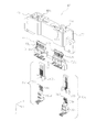
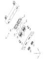
次に、図面を参照して本発明の第2の実施の形態に係るドッキングコネクタについて説明する。図9は、第2の実施の形態に係るプラグユニットとしてのプラグドッキングコネクタの外観を示す斜視図、図10は、第2の実施の形態に係るプラグドッキングコネクタの外観を示す底面図である。図9及び図10に示すように、プラグドッキングコネクタ75は、2つのUSB Type C規格準拠プラグコネクタ(以下、単にプラグコネクタという。)76a,76b、2つの追加プラグコネクタ77a,77b、2つのガイド部78a,78bを有する前カバー79、及び後ろカバー81を備えている。なお、ドッキングコネクタは、携帯型端末装置を外部機器に接続するために用いられるコネクタのことであり、機器本体に組み込まれるもの、ハウジング等により収容されケーブル等により機器と接続されているもの等、広義のドッキングコネクタのことを指す。
Next, a docking connector according to a second embodiment of the present invention will be described with reference to the drawings. FIG. 9 is a perspective view showing the external appearance of a plug docking connector as a plug unit according to the second embodiment, and FIG. 10 is a bottom view showing the external appearance of the plug docking connector according to the second embodiment. As shown in FIGS. 9 and 10, the
また、以下の説明においては、図9に示すXYZ直交座標系を設定し、この直交座標系を参照しつつ各部材の位置関係等について説明する。X軸は、2つのプラグコネクタ76a,76bを配置する方向に平行となるように設定されている。Y軸は、プラグドッキングコネクタ75をレセプタクルドッキングコネクタ73(図15参照)にドッキングさせる方向に平行となるように設定されている。Z軸は、YZ平面に直交する方向に設定されている。また、プラグコネクタ76b側が+X方向及びプラグコネクタ76a側が−X方向となるように、レセプタクルドッキングコネクタにプラグドッキングコネクタ75をドッキングさせる方向が+Y方向及びレセプタクルドッキングコネクタからプラグドッキングコネクタ75を抜去させる方向が−Y方向となるように設定されている。
In the following description, the XYZ orthogonal coordinate system shown in FIG. 9 is set, and the positional relationship of each member will be described with reference to this orthogonal coordinate system. The X axis is set to be parallel to the direction in which the two
図11は、プラグドッキングコネクタ75の構成を示す分解図、図12は、前カバー79を−Y方向から見た外観斜視図である。図9〜図12に示すように、前カバー79は、プラグコネクタ76a,76bを覆うカバーとして機能する。
11 is an exploded view showing the configuration of the
前カバー79は、2つのUSB Type C規格準拠レセプタクルコネクタ(以下、単にレセプタクルコネクタという。)113a,113bを備えたレセプタクルドッキングコネクタ73(図15参照)とドッキングする際、プラグコネクタ76a,76bが2つのレセプタクルコネクタ113a,113b(図15参照)と嵌合する前に、レセプタクルドッキングコネクタ73のガイド受入部102a,102b(図15参照)に挿入される2つのガイド部78a,78bを備えている。2つのガイド部78a,78bは、前カバー79と一体に形成されており、前カバー79及び2つのガイド部78a,78bは、樹脂により形成されている。ガイド部78aはプラグコネクタ76aの−X方向側に、ガイド部78bはプラグコネクタ76bの+X方向側に形成されている。
When the
ガイド部78aには、高強度を有する部材(この実施の形態では金属)95aがインサート成形されている。同様に、ガイド部78bには、高強度を有する部材(この実施の形態では金属)95bがインサート成形されている。金属95a,95bがガイド部78a,78bにインサート成形されることにより、ガイド部78a,78bの強度を増大させることができ、ガイド部78a,78bがレセプタクルドッキングコネクタ73のガイド受入部102a,102bに挿入される際、ガイド部78a,78bが破損するのを防止することができる。なお、金属95a,95bは、ガイド部78a,78bにインサート成形される以外に、嵌め込み、埋め込み等により組み込まれていてもよい。
A member (a metal in this embodiment) 95a having high strength is insert-molded in the
また、ガイド部78a,78bの+Y方向側の先端部は、プラグコネクタ76a,76bの+Y方向側の先端部より+Y方向に突出している。即ち、ガイド部78a,78bは、プラグコネクタ76a,76bより、ガイド部78a,78bがレセプタクルドッキングコネクタ73のガイド受入部102a,102bに挿入される挿入方向(+Y方向)側に突出している。したがって、ガイド部78a,78bは、プラグドッキングコネクタ75がレセプタクルドッキングコネクタ73とドッキングする際、プラグコネクタ76a,76bがレセプタクルコネクタ113a,113bと嵌合する前に、レセプタクルドッキングコネクタ73のガイド受入部102a,102bに挿入される。
Further, the + Y direction end portions of the
また、プラグコネクタ76a,76bを配列する配列方向に直交する方向(Z方向)におけるガイド部78a,78bの幅W(mm)は、レセプタクルコネクタ113a,113bの内径のZ方向における内径幅D(mm)以上である。なお、ガイド部78a,78bの幅W(mm)は、D≦W≦(D+0.6)であることが好ましく、D≦W≦(D+1)であることが更に好ましい。したがって、プラグドッキングコネクタ75がレセプタクルドッキングコネクタ73とドッキングする際、ガイド部78a,78bがレセプタクルコネクタ113a,113bに誤挿入されるのを防止することができる。
Further, the width W (mm) of the
また、ガイド部78aには、追加プラグコネクタ77aが配置、即ち組み込まれており、追加プラグコネクタ77aは、図10に示すように、複数のコンタクト116aを備えている。コンタクト116aは、追加レセプタクルコネクタ103aのコンタクト107aの接続端子108a(図21参照)と接続する接続面を有している。接続面は、ガイド部78aの+Z側の面と略同一面上に配置される。また、追加プラグコネクタ77aは、ガイド部78aの−Z側の面にも複数のコンタクト(図示せず)を備えている。図示しないコンタクトは、追加レセプタクルコネクタ103aのコンタクト107aの接続端子108a(図21参照)と接続する接続面を有している。接続面は、ガイド部78aの−Z側の面と略同一面上に配置される。追加プラグコネクタ77aのコンタクト116a及び図示しないコンタクトは、図11に示すケーブル96aに電気的に接続されている。
Further, an
また、ガイド部78bには、追加プラグコネクタ77bが配置、即ち組み込まれており、追加プラグコネクタ77bは、図10に示すように、複数のコンタクト116bを備えている。コンタクト116bは、追加レセプタクルコネクタ103b(図15参照)のコンタクトの接続端子(図示せず)と接続する接続面を有している。接続面は、ガイド部78bの+Z側の面と略同一面上に配置される。また、追加プラグコネクタ77bは、ガイド部78bの−Z側の面にも複数のコンタクト(図示せず)を備えている。図示しないコンタクトは、追加レセプタクルコネクタ103bのコンタクト107bの接続端子(図示せず)と接続する接続面を有している。接続面は、ガイド部78bの−Z側の面と略同一面上に配置される。追加プラグコネクタ77bのコンタクト116b及び図示しないコンタクトは、図11に示すケーブル96bに電気的に接続されている。
Further, an
また、前カバー79のガイド部78aとガイド部78bとの間の−X方向側には、プラグコネクタ76aを覆い、プラグコネクタ76aがレセプタクルコネクタ113a(図15参照)と嵌合する嵌合部80aを露出させるための開口部86aが形成されている。また、前カバー79のガイド部78aとガイド部78bとの間の+X方向側には、プラグコネクタ76bを覆い、プラグコネクタ76bがレセプタクルコネクタ113b(図15参照)と嵌合する嵌合部80bを露出させるための開口部86bが形成されている。
Further, the −X direction side between the
また、前カバー79(ガイド部78a,78bが形成されている面の裏面)には、図12に示すように、−X方向側にケーブル収容部97a,98a、+X方向側にケーブル収容部97b,98bが形成されている。ケーブル収容部97aは、+Z方向側に位置しており、ケーブル83a(図14参照)を収容する。ケーブル収容部98aは、−Z方向側に位置しており、ケーブル84a(図14参照)を収容する。ケーブル収容部97bは、+Z方向側に位置しており、ケーブル83b(図11参照)を収容する。ケーブル収容部98bは、−Z方向側に位置しており、ケーブル84b(図11参照)を収容する。
Further, as shown in FIG. 12, the front cover 79 (the back surface of the surface on which the
更に、前カバー79(ガイド部78a,78bが形成されている面の裏面)には、図12に示すように、−X方向側にケーブル保持部99a,100a、+X方向側にケーブル保持部99b,100bが形成されている。ケーブル保持部99aは、+Z方向側に位置しており、後ろカバー81のケーブル保持部69a(図11参照)と共に、ケーブル83a(図11参照)を保持する。ケーブル保持部100aは、−Z方向側に位置しており、後ろカバー81のケーブル保持部71a(図11参照)と共に、ケーブル84a(図11参照)を保持する。ケーブル保持部99bは、+Z方向側に位置しており、後ろカバー81のケーブル保持部69b(図11参照)と共に、ケーブル83b(図11参照)を保持する。ケーブル保持部100bは、−Z方向側に位置しており、後ろカバー81のケーブル保持部71b(図11参照)と共に、ケーブル84b(図11参照)を保持する。ケーブル保持部99a,99b,100a,100bのそれぞれは、後述する後ろカバー81のケーブル保持部69a,69b,71a,71bのそれぞれと共にケーブル83a,83b,84a,84bのそれぞれを保持する第2保持部として機能する。第2保持部の詳細については後述する。
Further, as shown in FIG. 12, the front cover 79 (the back surface of the surface on which the
また、プラグコネクタ76aの外壁部、即ち後述するプラグシェル65aと、開口部86aの+Y方向側に形成される壁部87aとの間には、図9に示すように、開口部86aが形成される面(ZX平面)において前カバー79(前カバー79に固定される後ろカバー81)に対してプラグコネクタ76aが移動できるように、所定のスペースが形成されている。同様に、プラグコネクタ76bの外壁部、即ち後述するプラグシェル65bと、開口部86bの+Y方向側に形成される壁部87bとの間には、開口部86bが形成される面(ZX平面)において前カバー79(前カバー79に固定される後ろカバー81)に対してプラグコネクタ76bが移動できるように、所定のスペースが形成されている。
Further, as shown in FIG. 9, an opening 86a is formed between an outer wall of the plug connector 76a, that is, a
プラグコネクタ76aの外壁部と前カバー79(開口部86aの−Y方向側に形成される壁部88a)との間には、制御部89aが設けられている。図13は、制御部89aの構成を示す図である。制御部89aは、導電性を有する部材、例えば金属からなり、制御部89aの+Z方向側には、図13に示すように、4つのZ側弾性部90aが形成されている。また、制御部89aの−Z方向側には、4つのZ側弾性部91aが形成されている。制御部89aは、開口部86aに組み込まれており、Z側弾性部90aは、プラグコネクタ76aの+Z方向側の外壁部を弾性力により−Z方向に押している。プラグコネクタ76aの+Z方向側の外壁部は、Z側弾性部90aの弾性力を受けている。Z側弾性部91aは、プラグコネクタ76aの−Z方向側の外壁部を弾性力により+Z方向に押している。プラグコネクタ76aの−Z方向側の外壁部は、Z側弾性部91aの弾性力を受けている。
A
制御部89aは、Z側弾性部90a,91aの弾性力を用いて、開口部86aに対するプラグコネクタ76aのZ方向における位置を制御する。例えば、プラグコネクタ76aに−Z方向の力を加えると、Z側弾性部90aは−Z方向に伸び、Z側弾性部91aは−Z方向に縮む。したがって、プラグコネクタ76aは、プラグコネクタ76aの外壁部と壁部88aとの間に形成されている所定のスペース内を−Z方向に移動する。プラグコネクタ76aに+Z方向の力を加えると、Z側弾性部90aは+Z方向に縮み、Z側弾性部91aは+Z方向に伸びる。したがって、プラグコネクタ76aは、プラグコネクタ76aの外壁部と壁部88aとの間に形成されている所定のスペース内を+Z方向に移動する。
The
また、制御部89aの+X方向側には、図13に示すように、2つのX側弾性部92aが形成されている。また、制御部89aの−X方向側には、2つのX側弾性部93aが形成されている。X側弾性部92aは、プラグコネクタ76aの+X方向側の外壁部を弾性力により−X方向に押している。プラグコネクタ76aの+X方向側の外壁部は、X側弾性部92aの弾性力を受けている。X側弾性部93aは、プラグコネクタ76aの−X方向側の外壁部を弾性力により+X方向に押している。プラグコネクタ76aの−X方向側の外壁部は、X側弾性部93aの弾性力を受けている。
Further, as shown in FIG. 13, two X-side
制御部89aは、X側弾性部92a,93aの弾性力を用いて、開口部86aに対するプラグコネクタ76aのX方向における位置を制御する。例えば、プラグコネクタ76aに−X方向の力を加えると、X側弾性部92aは−X方向に伸び、X側弾性部93aは−X方向に縮む。したがって、プラグコネクタ76aは、プラグコネクタ76aの外壁部と壁部88aとの間に形成されている所定のスペース内を−X方向に移動する。プラグコネクタ76aに+X方向の力を加えると、X側弾性部92aは+X方向に縮み、X側弾性部93aは+X方向に伸びる。したがって、プラグコネクタ76aは、プラグコネクタ76aの外壁部と壁部88aとの間に形成されている所定のスペース内を+X方向に移動する。
The
また、制御部89aの+Y方向側には、図13に示すように、4つのY側弾性部94aが形成されている。制御部89aは、Y側弾性部94a及び後ろカバー81に形成されている凸部67a(図11参照)を用いて、開口部86aに対するプラグコネクタ76aの姿勢を制御する。制御部89aの姿勢制御の詳細については、後述する。
Further, as shown in FIG. 13, four Y-side elastic portions 94a are formed on the + Y direction side of the
また、プラグコネクタ76bの外壁部と前カバー79(開口部86bの−Y方向側に形成される壁部88b)との間には、制御部89bが設けられている。制御部89bは、導電性を有する部材、例えば金属からなり、開口部86bに組み込まれている。制御部89bの+Z方向側には、制御部89aのZ側弾性部90aと同一の機能及び作用を有する4つのZ側弾性部が形成されている。また、制御部89bの−Z方向側には、制御部89aのZ側弾性部91aと同一の機能及び作用を有する4つのZ側弾性部が形成されている。
A
また、制御部89bの+X方向側には、制御部89aのX側弾性部92aと同一の機能及び作用を有する2つのX側弾性部が形成されている。また、制御部89bの−X方向側には、制御部89aのX側弾性部93aと同一の機能及び作用を有する2つのX側弾性部が形成されている。また、制御部89bの+Y方向側には、制御部89aのY側弾性部94aと同一の機能及び作用を有する4つのY側弾性部が形成されている。なお、制御部89bにおけるプラグコネクタ76bの位置制御及び姿勢制御は、制御部89aにおけるプラグコネクタ76aの位置制御及び姿勢制御と同一であるため、説明を省略する。
Further, two X-side elastic portions having the same function and action as the X-side
次に、プラグコネクタ76aの構成について説明する。図14は、図10のA−A断面図である。プラグコネクタ76aは、図11及び図14に示すように、回路基板82aに実装されている。プラグコネクタ76aは、図14に示すように、レセプタクルコネクタ113a,113b(図15参照)の複数のコンタクト(図示せず)と接続する複数のコンタクト85a及び複数のコンタクト59a、並びに複数のコンタクト85a,59aを覆うプラグシェル65aを備えている。複数のコンタクト85aそれぞれは、プラグコネクタ76aの+Z方向側に配置されており、コンタクト85aの−Y方向側の端部は、回路基板82aに半田付け等により固定されている。また、複数のコンタクト85aそれぞれは、+Y方向側の端部にレセプタクルコネクタ113a,113b(図15参照)のコンタクト(図示せず)と接触するための接点部61aを備えている。複数のコンタクト59aのそれぞれは、プラグコネクタ76aの−Z方向側に配置されており、コンタクト59aの−Y方向側の端部は、回路基板82aに半田付け等により固定されている。また、複数のコンタクト59aそれぞれは、+Y方向側の端部にレセプタクルコネクタ113a,113bのコンタクト(図示せず)と接触するための接点部63aを備えている。
Next, the configuration of the plug connector 76a will be described. 14 is a cross-sectional view taken along the line AA in FIG. The plug connector 76a is mounted on the
また、回路基板82aの+Z方向側には、複数のケーブル83aの一端が半田付け等により固定されている。複数のケーブル83aのそれぞれは、回路基板82aを介して、プラグコネクタ76aの+Z方向側に配置される複数のコンタクト85aのそれぞれに電気的に接続されている。また、回路基板82aの−Z方向側には、複数のケーブル84aの一端が半田付け等により固定されている。複数のケーブル84aのそれぞれは、回路基板82aを介して、プラグコネクタ76aの−Z方向側に配置される複数のコンタクト59aのそれぞれに電気的に接続されている。
Further, one end of a plurality of
次に、プラグコネクタ76bの構成について説明する。プラグコネクタ76bは、図11に示すように、回路基板82bに実装されている。また、プラグコネクタ76bは、図示しない複数のコンタクト及びプラグシェル65b(図9参照)を備えている。これらの構成は、プラグドッキングコネクタ75のY軸方向の中心線を線対称として、複数のコンタクト85a,59a及びプラグシェル65aの構成とそれぞれ同一である。また、回路基板82bの+Z方向側には、複数のケーブル83bの一端が半田付け等により固定されている。複数のケーブル83bのそれぞれは、プラグコネクタ76bの+Z方向側に配置される複数のコンタクト85bのそれぞれに電気的に接続されている。また、回路基板82bの−Z方向側には、複数のケーブル84bの一端が半田付け等により固定されている。複数のケーブル84bのそれぞれは、プラグコネクタ76bの−Z方向側に配置される複数のコンタクト(図示せず)のそれぞれに電気的に接続されている。
Next, the configuration of the
ここで、プラグコネクタ76a,76bを実装する回路基板82a,82bは、回路基板82a,82bに複数のケーブル83a,83bの一端が固定されていることから、複数のケーブル83a,83bの一端を保持する第1保持部として機能する。第1保持部の詳細については後述する。
Here, the
次に、後ろカバー81の構成について説明する。後ろカバー81は、図9に示すように、前カバー79に取り付けられ固定されており、プラグコネクタ76a,76bを−Y方向側から支持している。後ろカバー81の−X方向側には、図11に示すように、前カバー79と後ろカバー81との間に形成される空間から外部へ、ケーブル96aを導出するための開口部101aが形成されている。ケーブル96aは、開口部101a内において図示しない接着剤等により固定されている。また、後ろカバー81の+X方向側には、前カバー79と後ろカバー81との間に形成される空間から外部へ、ケーブル96bを導出するための開口部101bが形成されている。ケーブル96bは、開口部101b内において図示しない接着剤等により固定されている。
Next, the configuration of the
また、後ろカバー81の+Y方向側の面には、制御部89aの構成の一部である凸部67a、及び制御部89bの構成の一部である凸部67bが形成されている。2つの凸部67a,67bは、+Y方向側に凸面を有しており、凸部67aは、後ろカバー81の+X方向側に配置されており、+Y方向にプラグコネクタ76aを支持する。凸部67bは、後ろカバー81の−X方向側に配置されており、+Y方向にプラグコネクタ76bを支持する。
Further, on the surface on the + Y direction side of the
制御部89aは、Y側弾性部94a(図13参照)及び凸部67a(図11参照)を用いて、開口部86aに対するプラグコネクタ76aの姿勢、即ちY軸方向に対する傾きを制御する。例えば、Y軸方向に対して傾いた方向の力をプラグコネクタ76aに加えると、凸部67aがプラグコネクタ76aを支持する方向及びY側弾性部94aの弾性力が変化する。そして、プラグコネクタ76aの姿勢は、プラグシェル65aと壁部87aとの間に形成されている所定のスペース内において力を加えた方向に変化する。即ち、プラグコネクタ76aは、開口部86aが形成されている面に対して傾く。プラグコネクタ76aが傾いた側に配置されるY側弾性部94aは、その弾性力を用いてプラグコネクタ76aを押すことにより、プラグコネクタ76aの傾きを補正する補正部として機能する。プラグコネクタ76aに加えられた力が解除されると、プラグコネクタ76aは、Y側弾性部94aの弾性力により、プラグコネクタ76aに力が加えられる前の姿勢に戻る。
The
また、後ろカバー81には、図11に示すように、+Z方向側の側部にケーブル保持部69a,69b、−Z方向側の側部にケーブル保持部71a,71bが形成されている。ケーブル保持部69aは、−X方向側に位置しており、前カバー79のケーブル保持部99a(図12参照)と共に、ケーブル83aを保持する。ケーブル保持部69bは、+X方向側に位置しており、前カバー79のケーブル保持部99b(図12参照)と共に、ケーブル83bを保持する。ケーブル保持部71aは、−X方向側に位置しており、前カバー79のケーブル保持部100a(図12参照)と共に、ケーブル84aを保持する。ケーブル保持部71bは、+X方向側に位置しており、ケーブル保持部100b(図12参照)と共に、ケーブル84bを保持する。ケーブル保持部69a,69b,71a,71bのそれぞれは、前カバー79のケーブル保持部99a,99b,100a,100bのそれぞれと共にケーブル83a,83b,84a,84bのそれぞれを保持する第2保持部として機能する。
Further, as shown in FIG. 11, the
この第2の実施の形態において、ケーブル83a(図11参照)は、プラグコネクタ76aの移動に伴い追従するフレキシブル部を有し、フレキシブル部は、第1保持部としての回路基板82a(図11参照)と第2保持部としてのケーブル保持部99a(図12参照)及びケーブル保持部69a(図11参照)との間にあるケーブル収容部97a(図12参照)に収容されている。回路基板82aは、プラグコネクタ76aに対して固定されており、フレキシブル部であるケーブル83aの一端を保持する第1保持部として機能する。前カバー79のケーブル保持部99a及び後ろカバー81のケーブル保持部69aは、カバーである前カバー79及び後ろカバー81に設けられており、フレキシブル部であるケーブル83aの他端を保持する第2保持部として機能する。
In the second embodiment, the
このフレキシブル部、第1保持部及び第2保持部を備えることにより、プラグコネクタ76aは、前カバー79及び後ろカバー81に対して他の部材による制限を受けることなく移動することができる。なお、フレキシブル部は、ケーブル83aである必要はなく、例えばプラグコネクタ76aのコンタクト85aであってもよい。また、第1保持部は、回路基板82aである必要はなく、例えばプラグコネクタ76aであってもよい。
By providing the flexible portion, the first holding portion, and the second holding portion, the plug connector 76a can move without being restricted by other members with respect to the
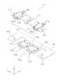
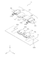
次に、図面を参照して本発明の第2の実施の形態に係るレセプタクルユニットとしてのレセプタクル側のドッキングコネクタ(以下、レセプタクルドッキングコネクタという。)について説明する。図15は、第2の実施の形態に係るレセプタクルドッキングコネクタの外観を示す斜視図、図16は、第2の実施の形態に係るレセプタクルドッキングコネクタの外観を示す正面図、図17は、第2の実施の形態に係るレセプタクルドッキングコネクタの外観を示す平面図、図18は、第2の実施の形態に係るレセプタクルドッキングコネクタの外観を示す底面図である。レセプタクルドッキングコネクタ73は、タブレット型PC等の携帯型端末装置(電子機器)に搭載されており、図15に示すように、2つのレセプタクルコネクタ113a,113b、2つの追加レセプタクルコネクタ103a,103b及び2つのガイド受入部102a,102bを有するガイドシェル104を備えている。
Next, a receptacle-side docking connector (hereinafter referred to as “receptacle docking connector”) as a receptacle unit according to a second embodiment of the present invention will be described with reference to the drawings. FIG. 15 is a perspective view showing the appearance of the receptor clock docking connector according to the second embodiment, FIG. 16 is a front view showing the appearance of the receptor clock docking connector according to the second embodiment, and FIG. The top view which shows the external appearance of the receptor clock docking connector which concerns on this Embodiment, FIG. 18: is a bottom view which shows the external appearance of the receptor clock docking connector which concerns on 2nd Embodiment. The
図19及び図20はレセプタクルドッキングコネクタ73の構成について説明するための分解図であり、図19は正面側から見た斜視図、図20は背面側から見た斜視図である。レセプタクルコネクタ113aは、プラグコネクタ76a(図9参照)と嵌合し、図16に示すように、レセプタクルコネクタ113aが備えるコンタクト等(図示せず)を覆うレセプタクルシェル105aを備えている。レセプタクルコネクタ113bは、プラグコネクタ76b(図9参照)と嵌合し、図16に示すように、レセプタクルコネクタ113bが備えるコンタクト等(図示せず)を覆うレセプタクルシェル105bを備えている。
19 and 20 are exploded views for explaining the configuration of the receptor
レセプタクルコネクタ113a,113bは、プラグコネクタ76a,76bと嵌合する嵌合方向(Y方向)と基板106の実装面(+Z方向側の面)とが平行となるように実装面に実装されている。また、レセプタクルコネクタ113a,113bは、それぞれ個別に基板106に実装されている。即ち、レセプタクルコネクタ113aは、レセプタクルコネクタ113bとは別に基板106に実装されている。なお、この第2の実施の形態では、2つのレセプタクルコネクタ113a,113bを備えているが、3つ以上のレセプタクルコネクタを備えるようにしてもよい。また、3つ以上のレセプタクルコネクタを備える場合には、3つ以上のレセプタクルコネクタのうちの少なくとも1つのレセプタクルコネクタは、他の少なくとも1つのレセプタクルコネクタとは別に基板106に実装される。例えば、3つのレセプタクルコネクタを備える場合には、各レセプタクルコネクタが個別に基板106に実装、または2つのレセプタクルコネクタが一体に基板106に実装され1つのレセプタクルコネクタが他の2つのレセプタクルコネクタとは別に基板106に実装される。
追加レセプタクルコネクタ103aは、図15に示すように、レセプタクルドッキングコネクタ73の−X方向側に位置しており、ガイド受入部102a内に配置されている。図21は、図16のB−B断面図である。追加レセプタクルコネクタ103aは、図16及び図21に示すように、複数(この第2の実施の形態では12個)のコンタクト107aを備えている。コンタクト107aの一端部には、図21に示すように、追加プラグコネクタ77aのコンタクト116a及び図示しないコンタクトと接続する弾性体の接続端子108aが形成されている。コンタクト107aの他端部は、図21に示すように、電線109aと電気的に接続されている。
As shown in FIG. 15, the
追加レセプタクルコネクタ103bは、図15に示すように、レセプタクルドッキングコネクタ73の+X方向側に位置しており、ガイド受入部102b内に配置されている。追加レセプタクルコネクタ103bは、複数(この第2の実施の形態では12個)のコンタクト107bを備えている。コンタクト107bの一端部には、追加レセプタクルコネクタ103aのコンタクト107aと同様に、追加プラグコネクタ77bのコンタクト116b及び図示しないコンタクトと接続する弾性体の接続端子(図示せず)が形成されている。コンタクト107bの他端部は、電線109bと電気的に接続されている。
As shown in FIG. 15, the
なお、上述の第2の実施の形態においては、プラグコネクタ76aをレセプタクルコネクタ113aに、プラグコネクタ76bをレセプタクルコネクタ113bに嵌合させる場合を例に挙げて説明した。この場合においては、追加レセプタクルコネクタ103aと追加プラグコネクタ77aとが嵌合し、追加レセプタクルコネクタ103bと追加プラグコネクタ77bとが嵌合する。しかしながら、この第2の実施の形態に係るプラグドッキングコネクタ75及びレセプタクルドッキングコネクタ73は、リバーシブルコネクタであり、レセプタクルコネクタ113aとプラグコネクタ76bとを、レセプタクルコネクタ113bとプラグコネクタ76aとを嵌合させることも可能である。この場合においては、追加レセプタクルコネクタ103aと追加プラグコネクタ77bとが嵌合し、追加レセプタクルコネクタ103bは追加プラグコネクタ77aとが嵌合する。
In the above-described second embodiment, the case where the plug connector 76a is fitted to the
次に、ガイドシェル104の構成について説明する。ガイドシェル104は、金属等により形成されており、−X方向側に配置されるガイド受入部102a及び追加レセプタクルコネクタ103a、並びに+X方向側に配置されるガイド受入部102b及び追加レセプタクルコネクタ103bを備えている。即ち、ガイド受入部102a,102bは、一体に形成されている。ガイドシェル104は、図15に示すように、レセプタクルコネクタ113a,113bの+Z方向側の外周を覆っている。
Next, the configuration of the
また、ガイドシェル104は、図20に示すように、ガイド部78a,78b(図9参照)をガイド受入部102a,102bに挿入する挿入方向(+Y方向)に対して、レセプタクルコネクタ113a,113bを支持する支持部110a,110bを備えている。ガイドシェル104(支持部110a,110b)は、図20に示すように、レセプタクルコネクタ113a,113bの+Y方向側の外周を覆っている。支持部110a,110bは、ガイド部78a,78bをガイド受入部102a,102bに挿入する際に生じる+Y方向にかかる力を受ける。また、支持部110a,110bは、レセプタクルコネクタ113a,113bの基板106への取り付け強度を上げる。
As shown in FIG. 20, the
また、ガイドシェル104には、追加レセプタクルコネクタ103aの近傍の−X方向側にネジを通すための孔111a、追加レセプタクルコネクタ103bの近傍の+X方向側にネジを通すための孔111bが設けられている。また、ガイドシェル104には、追加レセプタクルコネクタ103aとレセプタクルコネクタ113aとの間にネジを通すための孔114a、レセプタクルコネクタ113aとレセプタクルコネクタ113bとの間にネジを通すための孔114b、レセプタクルコネクタ113bと追加レセプタクルコネクタ103bとの間にネジを通すための孔114cが設けられている。孔111a,111b,114a〜114cは、携帯型端末装置の筐体にガイドシェル104を固定するための固定部として機能する。孔111aと基板106に形成されているネジを通すための孔112aとにネジを通し、孔111bと基板106に形成されているネジを通すための孔112bとにネジを通し、孔114aと基板106に形成されているネジを通すための孔115aとにネジを通し、孔114bと基板106に形成されているネジを通すための孔115bとにネジを通し、孔114cと基板106に形成されているネジを通すための孔115cとにネジを通し、ガイドシェル104及び基板106は、携帯型端末装置の筐体(図示せず)にネジ止めされる。即ち、ガイドシェル104は、レセプタクルコネクタ113a,113bが基板106に実装された後、基板106と共に該筐体に固定される。このとき、ガイドシェル104は、基板106の実装面(+Z方向側の面)に対向する位置(+Z方向側)から携帯型端末装置の筐体に取り付けられる。
Further, the
図22は、図17のC−C断面図である。ガイドシェル104とレセプタクルコネクタ113aのレセプタクルシェル105aとは、図22に示すように、導通している。同様に、ガイドシェル104とレセプタクルコネクタ113bのレセプタクルシェル105bとは、導通している。
22 is a cross-sectional view taken along the line CC of FIG. The
この第2の実施の形態に係るプラグドッキングコネクタ75によれば、ガイド部78a,78bを備えているため、プラグコネクタ76a,76bがレセプタクルコネクタ113a,113bと嵌合する前に、ガイド部78a,78bがレセプタクルドッキングコネクタ73のガイド受入部102a,102bに挿入される。したがって、プラグコネクタ76a,76bをレセプタクルコネクタ113a,113bに損傷なく確実に嵌合させることができる。
According to the
また、この第2の実施の形態に係るプラグドッキングコネクタ75によれば、制御部89a,89bを備え、プラグコネクタ76a,76bが回路基板82a,82bを介してケーブル83a,83b,84a,84b(フレキシブル部)に接続されており、フレキシブル部は第1保持部及び第2保持部に保持されている。したがって、プラグコネクタ76a,76bの位置制御及び姿勢制御を行うことができる。即ち、プラグコネクタ76a,76bが所定のスペース内において移動可能に構成されているため、公差を最小限に抑えることができ、プラグコネクタ76a,76bをレセプタクルコネクタ113a,113bに損傷なく確実に嵌合させることができる。また、レセプタクルコネクタ113a,113bと嵌合していない場合においては、制御部89a,89bによる位置制御及び姿勢制御により、プラグコネクタ76a,76bを所定の位置及び所定の姿勢に維持することができる。即ち、プラグコネクタ76a,76bの実装時における位置及び姿勢のずれを確実に吸収することができる。
Further, according to the
また、この第2の実施の形態に係るレセプタクルドッキングコネクタ73によれば、ガイド受入部102a,102bを備えているため、プラグコネクタ76a,76bがレセプタクルコネクタ113a,113bと嵌合する前に、ガイド部78a,78bがガイド受入部102a,102bに挿入される。したがって、プラグコネクタ76a,76bをレセプタクルコネクタ113a,113bに損傷なく確実に嵌合させることができる。
Further, according to the
また、この第2の実施の形態に係るレセプタクルドッキングコネクタ73によれば、レセプタクルコネクタ113a,113bをそれぞれ個別に基板106に実装し、その後基板106を携帯型端末装置の筐体に取り付ける際に基板106と共にガイドシェル104を取り付ける。したがって、基板106の実装面に対するレセプタクルドッキングコネクタ73の平坦度(コプラナリティ)を良好に維持することができ、平坦度が劣ることによる半田付け不良を防止することができる。
In addition, according to the
また、この第2の実施の形態に係るレセプタクルドッキングコネクタ73によれば、ガイドシェル104によりレセプタクルコネクタ113a,113bを覆い、ガイドシェル104とレセプタクルシェル105a,105bとが導通している。したがって、レセプタクルシェル105a,105bがレセプタクルコネクタ113a,113bのインナーシェルとして機能しているのに対し、ガイドシェル104をレセプタクルコネクタ113a,113bのアウターシェルとして機能させることができる。また、ガイドシェル104がレセプタクルコネクタ113a,113bを覆い、基板106に固定されているため、レセプタクルコネクタ113a,113bの基板106への取り付け強度を向上させることができる。
Further, according to the
また、複数の標準規格準拠のコネクタ等の所定規格コネクタを有するドッキングコネクタに更にコネクタを追加した場合、ドッキングコネクタのサイズが大きくなるという問題があったが、この第2の実施の形態に係るプラグドッキングコネクタ75によれば、ガイド部78a,78bに追加プラグコネクタ77a,77bを配置するため、プラグドッキングコネクタ75を小型化することができる。同様に、この第2の実施の形態に係るレセプタクルドッキングコネクタ73によれば、ガイド受入部102a,102bに追加レセプタクルコネクタ103a,103bを配置するため、レセプタクルドッキングコネクタ73を小型化することができる。
Further, when a connector is further added to a docking connector having a predetermined standard connector such as a plurality of standards-compliant connectors, there is a problem that the size of the docking connector is increased. The plug according to the second embodiment According to the
なお、上述の第2の実施の形態に係るプラグドッキングコネクタ75においては、プラグコネクタ76a,76bが回路基板82a,82bに実装されており、プラグコネクタ76a,76bのコンタクト85a,59a,85bとケーブル83a,83b,84a,84bとが回路基板82a,82bを介して電気的に接続されている。しかしながら、これに代えて、例えば図23に示すようなプラグドッキングコネクタ117を用いてもよい。図23はプラグドッキングコネクタ117の外観を示す斜視図、図24はプラグドッキングコネクタ117の外観を示す底面図、図25はプラグドッキングコネクタ117の構成を示す分解図、図26は図24のE−E断面図である。
In the
図25及び図26に示すように、プラグドッキングコネクタ117を構成するプラグコネクタ118a,118bは回路基板に実装されておらず、プラグコネクタ118a,118bの複数のコンタクト119a,119bとケーブル120a,120bとが半田付け等により直接接続されている。プラグドッキングコネクタ117が電子機器等に搭載される場合であって、電子機器に搭載されるプリント基板との相対位置が異なる場合であっても、プラグコネクタ118a,118bの複数のコンタクト119a,119bの形状や長さを変更することなく、プリント基板に容易に接続することができる。即ち、コンタクト119a,119bがケーブル120a,120bに接続されているため、ケーブル120a,120bを電子機器のプリント基板に接続することにより、プラグコネクタ118a,118bとプリント基板とをケーブル120a,120bを介して電気的に接続することができる。
As shown in FIGS. 25 and 26, the
また、上述の第2の実施の形態に係るプラグドッキングコネクタ75においては、制御部89aがプラグコネクタ76aの位置及び姿勢を制御し、且つ制御部89bがプラグコネクタ76bの位置及び姿勢を制御しているが、制御部89aのみを備える構成、または制御部89bのみを備える構成にしてもよい。制御部89a(または89b)のみを備える場合には、予めプラグコネクタ76b(または76a)の位置及び姿勢を規定し、プラグコネクタ76a(または76b)のみの位置及び姿勢を制御する。
In the
また、上述の第2の実施の形態に係るプラグドッキングコネクタ75においては、制御部89a,89bがY側弾性部94a及び後ろカバー81の凸部67a,67bを用いてプラグコネクタ76a,76bの姿勢を制御しているが、回路基板82a,82bと後ろカバー81との間に弾性部と凸部を有する姿勢制御部を備え、この姿勢制御部によりプラグコネクタ76a,76bの姿勢を制御してもよい。
Further, in the
また、上述の第2の実施の形態に係るレセプタクルドッキングコネクタ73においては、図21に示すように、コンタクト107a,107bの他端部が電線109a,109bと電気的に接続されているが、これに代えて、追加レセプタクルコネクタ103,103bが追加プラグコネクタ77a,77bと嵌合する第1嵌合部とは別に基板106に予め実装されているコネクタと嵌合する第2嵌合部を備えるようにしてもよい。この場合には、コンタクト107a,107bの一端部は追加プラグコネクタ77a,77bのコンタクト116a,116b及び図示しないコンタクトと電気的に接続し、コンタクト107a,107bの他端部は基板106に予め実装されているコネクタのコンタクトと電気的に接続する。
In the receptor
また、上述の第2の実施の形態に係るレセプタクルドッキングコネクタ73においては、図21に示すように、コンタクト107a,107bの他端部が電線109a,109bと電気的に接続されているが、これに代えて、例えば図27に示すようなレセプタクルドッキングコネクタ121を用いてもよい。図27はレセプタクルドッキングコネクタ121の外観を示す斜視図、図28はレセプタクルドッキングコネクタ121の外観を示す正面図、図29はレセプタクルドッキングコネクタ121の構成を示す分解図、図30は図28のF−F断面図である。図27〜図30に示すように、レセプタクルドッキングコネクタ121を構成する追加レセプタクルコネクタ122a,122bのコンタクト123a,123bには、電線が接続されていない。また、レセプタクルドッキングコネクタ121を構成するガイドシェル124は、プラグドッキングコネクタのガイド部をガイド受入部125a,125bに挿入する挿入方向(+Y方向)に対して、追加レセプタクルコネクタ122a,122bを支持している。
In the receptor
また、上述の第2の実施の形態に係るレセプタクルドッキングコネクタ73においては、2つのガイド受入部102a,102bを備えているが、1つのガイド受入部または3つ以上のガイド受入部を備えるようにしてもよい。3つ以上のガイド受入部を備える場合であっても、ガイド受入部は一体に形成される。
Further, in the
また、この第2の実施の形態に係るレセプタクルドッキングコネクタ73によれば、リバーシブルコネクタであり、2つの追加レセプタクルコネクタ103a,103bを備えているが、1つの追加レセプタクルコネクタを備えるようにしてもよい。この場合においては、プラグコネクタ76aがレセプタクルコネクタ113aと嵌合する際、追加プラグコネクタ77aが追加レセプタクルコネクタと嵌合し、プラグコネクタ76bがレセプタクルコネクタ113bと嵌合する際、追加プラグコネクタ77bが追加レセプタクルコネクタと嵌合する。
In addition, according to the
また、上述の第2の実施の形態においては、ガイド部78a,78bの先端部のみがプラグコネクタ76a,76bの先端部より突出しているが、ガイド受入部102a,102bの先端部のみがレセプタクルコネクタ113a,113bの先端部より突出していてもよい。また、ガイド部78a,78bの先端部がプラグコネクタ76a,76bの先端部より突出し、且つガイド受入部102a,102bの先端部がレセプタクルコネクタ113a,113bの先端部より突出していてもよい。
In the second embodiment described above, only the distal ends of the
なお、上述の各実施の形態に係るプラグドッキングコネクタにおいては、2つのUSB Type C規格準拠プラグコネクタを備えているが、3つ以上のUSB Type C規格準拠プラグコネクタを備えてもよい。また、USB Type C規格準拠プラグコネクタに代えて、USB Type C規格準拠プラグコネクタ以外の複数の標準規格準拠のプラグコネクタを備えてもよい。また、標準規格準拠のプラグコネクタ以外の所定の規格を有する複数の所定規格プラグコネクタを備えてもよい。 Note that the plug docking connector according to each of the above embodiments includes two USB Type C standard compliant plug connectors, but may include three or more USB Type C standard compliant plug connectors. Further, instead of the USB Type C standard compliant plug connector, a plurality of standard standard compliant plug connectors other than the USB Type C standard compliant plug connector may be provided. Also, a plurality of predetermined standard plug connectors having a predetermined standard other than the standard-compliant plug connector may be provided.
同様に、上述の各実施の形態に係るレセプタクルドッキングコネクタにおいては、2つのUSB Type C規格準拠レセプタクルコネクタを備えているが、3つ以上のUSB Type C規格準拠レセプタクルコネクタを備えてもよい。また、USB Type C規格準拠レセプタクルコネクタに代えて、USB Type C規格準拠レセプタクルコネクタ以外の複数の標準規格準拠のレセプタクルコネクタを備えてもよい。また、標準規格準拠のレセプタクルコネクタ以外の所定の規格を有する複数の所定規格レセプタクルコネクタを備えてもよい。 Similarly, the receptacle clocking connector according to each of the above embodiments includes two USB Type C standard compliant receptacle connectors, but may include three or more USB Type C standard compliant receptacle connectors. In place of the USB Type C standard compliant receptacle connector, a plurality of standard standard compliant receptacle connectors other than the USB Type C standard compliant receptacle connector may be provided. In addition, a plurality of predetermined standard receptacle connectors having a predetermined standard other than the standard-compliant receptacle connector may be provided.
また、上述の各実施の形態においては、プラグコネクタの位置及び姿勢を制御しているが、プラグコネクタの位置のみを制御する構成にしてもよく、またはプラグコネクタの姿勢のみを制御する構成にしてもよい。 Further, in each of the above-described embodiments, the position and orientation of the plug connector are controlled. However, only the position of the plug connector may be controlled, or only the orientation of the plug connector may be controlled. Also good.
また、上述の各実施の形態に係るプラグドッキングコネクタにおいては、2つまたは4つの追加プラグコネクタを備えているが、1つ、3つまたは5つ以上の追加プラグコネクタを備えてもよい。同様に、上述の各実施の形態に係るレセプタクルドッキングコネクタにおいては、2つまたは4つの追加レセプタクルコネクタを備えているが、1つ、3つまたは5つ以上の追加レセプタクルコネクタを備えてもよい。 Further, the plug docking connector according to each of the above-described embodiments includes two or four additional plug connectors, but may include one, three, five, or more additional plug connectors. Similarly, the receptacle docking connector according to each of the above-described embodiments includes two or four additional receptacle connectors, but may include one, three, or five or more additional receptacle connectors.
2,64…プラグドッキングコネクタ、4a,4b…プラグコネクタ、6a〜6d…追加プラグコネクタ、8a〜8d…ガイド、10…ガイドハウジング、12a,12b,14a,14b…コンタクト、16,18…インサートハウジング、20a,20b…グランドプレート、22…連結部、24a,24b,26a,26b…グランドコンタクト、28a,28b…ハウジング、30a,30b,31a,31b…グランドプレートコンタクト、32a,32b…シェル、34a,34b…コンタクト、42,70…レセプタクルドッキングコネクタ、44a〜44d…レセプタクルコネクタ、46a,46b…追加レセプタクルコネクタ、48a〜48d…ガイド挿入部、49a,49b…コンタクト、50…ガイドシェル、52a,52b…レセプタクルグランドシェル、54…レセプタクルハウジング、56a,56b…コンタクト,58a,58b…接続端子、60a,60b…追加レセプタクルハウジング、61a,63a…接点部、62a,62b…レセプタクルガイドハウジング、65a,65b…プラグシェル,67a,67b…凸部、69a,69b,71a,71b,99a,99b,100a,100b…ケーブル保持部、73,121…レセプタクルドッキングコネクタ、75,117…プラグドッキングコネクタ、76a,76b,118a,118b…プラグコネクタ、77a,77b…追加プラグコネクタ、78a,78b…ガイド部、79…前カバー、80a,80b…嵌合部、81…後ろカバー、82a,82b…回路基板、83a,83b,84a,84b,96a,96b,120a,120b…ケーブル、85a,85b,59a,107a,107b,116a,116b,119a,119b,123a,123b…コンタクト、86a,86b,101a,101b…開口部、87a,87b,88a,88b…壁部、89a,89b…制御部、90a,91a…Z側弾性部、92a,93a…X側弾性部、94a…Y側弾性部、95a,95b…金属、97a,97b,98a,98b…ケーブル収容部、102a,102b,125a,125b…ガイド受入部、103a,103b,122a,122b…追加レセプタクルコネクタ、104,124…ガイドシェル、105a,105b…レセプタクルシェル、106…基板、108a…接続端子、109a,109b…電線、110a,110b…支持部、111a,111b,112a,112b,114a〜114c,115a〜115c…孔、113a,113b…レセプタクルコネクタ。
2, 64 ... plug docking connector, 4a, 4b ... plug connector, 6a-6d ... additional plug connector, 8a-8d ... guide, 10 ... guide housing, 12a, 12b, 14a, 14b ... contact, 16, 18 ... insert
また、本発明のプラグユニットは、複数の所定規格プラグコネクタと、前記複数の所定規格プラグコネクタを覆うカバーとを備えたプラグユニットであって、複数の所定規格レセプタクルコネクタを備えたレセプタクルユニットとドッキングする際、前記所定規格プラグコネクタが前記所定規格レセプタクルコネクタと嵌合する前に、前記レセプタクルユニットのガイド挿入部に挿入されるガイド部を備え、前記ガイド部は、前記カバーと一体に形成されていることを特徴とする。 The plug unit of the present invention is a plug unit including a plurality of predetermined standard plug connectors and a cover covering the plurality of predetermined standard plug connectors, and the receptacle unit including the plurality of predetermined standard receptacle connectors and the docking unit. When the predetermined standard plug connector is fitted with the predetermined standard receptacle connector , the guide unit is inserted into a guide insertion part of the receptacle unit, and the guide part is formed integrally with the cover. It is characterized by being.
また、本発明のレセプタクルユニットは、複数の所定規格レセプタクルコネクタを備え、電子機器に搭載されるレセプタクルユニットであって、複数の所定規格プラグコネクタを備えたプラグユニットとドッキングする際、前記所定規格レセプタクルコネクタが前記所定規格プラグコネクタと嵌合する前に、前記プラグユニットのガイド部を受け入れる少なくとも1つのガイド受入部を備え、前記複数の所定規格レセプタクルコネクタのうちの少なくとも1つの前記所定規格レセプタクルコネクタは、他の少なくとも1つの前記所定規格レセプタクルコネクタとは別に基板に実装されており、少なくとも2つの前記ガイド受入部を備える場合、前記少なくとも2つの前記ガイド受入部は、一体に形成されており、前記ガイド受入部は、前記所定規格レセプタクルコネクタが前記基板に実装された後、前記基板に固定されることを特徴とする。 The receptacle unit of the present invention includes a plurality of predetermined standard receptacle connectors, and is a receptacle unit that is mounted on an electronic device. When docked with a plug unit having a plurality of predetermined standard plug connectors, the predetermined standard receptacle The connector includes at least one guide receiving portion that receives a guide portion of the plug unit before the connector is fitted to the predetermined standard plug connector, and at least one predetermined standard receptacle connector of the plurality of predetermined standard receptacle connectors includes: The at least two guide receiving portions are integrally formed when mounted on a substrate separately from at least one other predetermined standard receptacle connector and provided with at least two guide receiving portions, The guide receiving part After standard receptacle connector is mounted on the substrate, characterized in that it is fixed to the substrate.
また、本発明のレセプタクルユニットは、前記第2追加コネクタが第1追加コネクタと嵌合する第1嵌合部と、前記基板に実装されているコネクタと嵌合する第2嵌合部とを備えることを特徴とする。 In addition, the receptacle unit of the present invention includes a first fitting portion where the second additional connector is fitted to the first additional connector, and a second fitting portion which is fitted to the connector mounted on the board. It is characterized by that.
また、プラグコネクタ4aはシェル32aを有しており、シェル32aは、ハウジング28aの外周、インサートハウジング16の複数のコンタクト12aを保持する側(−Y方向側)、及びインサートハウジング18の複数のコンタクト14aを保持する側(−Y方向側)を覆っている。同様に、プラグコネクタ4bはシェル32bを有しており、シェル32bは、ハウジング28bの外周、インサートハウジング16の複数のコンタクト12bを保持する側(+Y方向側)、及びインサートハウジング18の複数のコンタクト14bを保持する側(+Y方向側)を覆っている。
The plug connector 4a has a
また、上述の第2の実施の形態に係るレセプタクルドッキングコネクタ73においては、図21に示すように、コンタクト107a,107bの他端部が電線109a,109bと電気的に接続されているが、これに代えて、追加レセプタクルコネクタ103a,103bが追加プラグコネクタ77a,77bと嵌合する第1嵌合部とは別に基板106に予め実装されているコネクタと嵌合する第2嵌合部を備えるようにしてもよい。この場合には、コンタクト107a,107bの一端部は追加プラグコネクタ77a,77bのコンタクト116a,116b及び図示しないコンタクトと電気的に接続し、コンタクト107a,107bの他端部は基板106に予め実装されているコネクタのコンタクトと電気的に接続する。
In the receptor
Claims (29)
前記所定規格プラグコネクタは、所定規格レセプタクルコネクタの接続端子と接続するコンタクトを備え、
前記複数の所定規格プラグコネクタそれぞれが有する前記コンタクトを保持すると共に、前記複数の所定規格プラグコネクタそれぞれの間隔及び前記所定規格プラグコネクタの姿勢を規定する1つの絶縁体を備えることを特徴とするプラグユニット。 A plug unit having a plurality of predetermined standard plug connectors,
The predetermined standard plug connector includes a contact connected to a connection terminal of the predetermined standard receptacle connector,
A plug comprising: one insulator that holds the contacts of each of the plurality of predetermined standard plug connectors and defines the interval between the plurality of predetermined standard plug connectors and the attitude of the predetermined standard plug connector. unit.
複数の所定規格レセプタクルコネクタを備えたレセプタクルユニットとドッキングする際、前記所定規格プラグコネクタが前記プラグユニットと嵌合する前に、前記レセプタクルユニットのガイド挿入部に挿入されるガイド部を備え、
前記ガイド部は、前記カバーと一体に形成されていることを特徴とするプラグユニット。 A plug unit comprising a plurality of predetermined standard plug connectors and a cover covering the plurality of predetermined standard plug connectors,
When docking with a receptacle unit having a plurality of predetermined standard receptacle connectors, the guide unit is inserted into a guide insertion portion of the receptacle unit before the predetermined standard plug connector is fitted to the plug unit,
The plug unit, wherein the guide portion is formed integrally with the cover.
前記所定規格プラグコネクタの外壁部と前記開口部を形成する壁部との間には、前記所定規格レセプタクルコネクタと嵌合する嵌合方向と交差する交差平面において前記所定規格プラグコネクタが移動できるように、所定のスペースが形成されており、
前記開口部に対する少なくとも1つの前記所定規格プラグコネクタの位置及び姿勢の少なくとも一方を制御する制御部を備えることを特徴とする請求項4記載のプラグユニット。 The cover has an opening for exposing a fitting portion to be fitted to the predetermined standard receptacle connector of the predetermined standard plug connector;
The predetermined standard plug connector can move between an outer wall portion of the predetermined standard plug connector and a wall portion forming the opening in an intersecting plane intersecting a fitting direction in which the predetermined standard receptacle connector is fitted. And a predetermined space is formed,
The plug unit according to claim 4, further comprising a control unit that controls at least one of a position and a posture of at least one predetermined standard plug connector with respect to the opening.
前記ガイド部には、金属が組み込まれていることを特徴とする請求項4または請求項5記載のプラグユニット。 The guide part and the cover are made of resin,
The plug unit according to claim 4 or 5, wherein a metal is incorporated in the guide portion.
複数の所定規格レセプタクルコネクタを備えたレセプタクルユニットとドッキングする際、前記所定規格プラグコネクタが前記所定規格レセプタクルコネクタと嵌合する前に、前記レセプタクルユニットのガイド挿入部に挿入されるガイド部と、
前記ガイド部に配置される第1追加コネクタと、
を備えることを特徴とするプラグユニット。 A plug unit having a plurality of predetermined standard plug connectors,
A guide portion inserted into a guide insertion portion of the receptacle unit before the predetermined standard plug connector is fitted to the predetermined standard receptacle connector when docked with a receptacle unit including a plurality of predetermined standard receptacle connectors;
A first additional connector disposed in the guide portion;
A plug unit comprising:
複数の前記所定規格プラグコネクタのそれぞれが有する前記コンタクトを保持すると共に、複数の前記所定規格プラグコネクタそれぞれの間隔及び前記所定規格プラグコネクタの姿勢を規定する1つの絶縁体を備えることを特徴とする請求項4または請求項8記載のプラグユニット。 The predetermined standard plug connector includes a contact connected to a connection terminal of the predetermined standard receptacle connector,
A plurality of the predetermined standard plug connectors are held by the contacts, and each of the predetermined standard plug connectors is provided with a single insulator that defines an interval between the predetermined standard plug connectors and an attitude of the predetermined standard plug connector. The plug unit according to claim 4 or 8.
前記第1コンタクトの前記接続面は、前記ガイド部の表面に配置されることを特徴とする請求項7〜請求項14の何れか一項に記載のプラグユニット。 The first additional connector includes a first contact having a connection surface connected to a connection terminal of the second additional connector,
The plug unit according to any one of claims 7 to 14, wherein the connection surface of the first contact is disposed on a surface of the guide portion.
前記レセプタクルユニットは、一方の前記第1追加コネクタ及び他方の前記第1追加コネクタと接続可能な少なくとも1つの前記第2追加コネクタを備えることを特徴とする請求項16記載のプラグユニット。 Comprising at least two said first additional connectors;
The plug unit according to claim 16, wherein the receptacle unit includes at least one second additional connector connectable to one of the first additional connector and the other first additional connector.
複数の所定規格プラグコネクタを備えたプラグユニットとドッキングする際、前記所定規格レセプタクルコネクタが前記所定規格プラグコネクタと嵌合する前に、前記プラグユニットのガイド部を受け入れる少なくとも1つのガイド受入部を備え、
前記複数の所定規格レセプタクルコネクタのうちの少なくとも1つの前記所定規格レセプタクルコネクタは、他の少なくとも1つの前記所定規格レセプタクルコネクタとは別に基板に実装されており、
少なくとも2つの前記ガイド受入部を備える場合、前記少なくとも2つの前記ガイド受入部は、一体に形成されており、
前記ガイド受入部は、前記所定規格レセプタクルコネクタが前記基板に実装された後、前記基板に固定されることを特徴とするレセプタクルユニット。 A receptacle unit connector comprising a plurality of predetermined standard receptacle connectors and mounted on an electronic device,
When docking with a plug unit having a plurality of predetermined standard plug connectors, the plug unit includes at least one guide receiving portion that receives a guide portion of the plug unit before the predetermined standard receptacle connector is fitted to the predetermined standard plug connector. ,
The at least one predetermined standard receptacle connector of the plurality of predetermined standard receptacle connectors is mounted on a substrate separately from at least one other predetermined standard receptacle connector,
When including at least two of the guide receiving portions, the at least two of the guide receiving portions are integrally formed,
The receptacle unit is characterized in that the guide receiving portion is fixed to the substrate after the predetermined standard receptacle connector is mounted on the substrate.
前記第2コンタクトの一端部は、第1追加コネクタの第1コンタクトと電気的に接続され、
前記第2コンタクトの他端部は、電線と電気的に接続されることを特徴とする請求項20記載のレセプタクルユニット。 The second additional connector includes a second contact;
One end of the second contact is electrically connected to the first contact of the first additional connector;
The receptacle unit according to claim 20, wherein the other end of the second contact is electrically connected to an electric wire.
前記第1追加コネクタと嵌合する第1嵌合部と、
前記基板に実装されているコネクタと嵌合する第2嵌合部と、
を備えることを特徴とする請求項20記載のレセプタクルユニット。 The second additional connector is
A first fitting portion for fitting with the first additional connector;
A second fitting portion for fitting with a connector mounted on the substrate;
The receptacle unit according to claim 20, further comprising:
前記ガイド受入部と前記所定規格レセプタクルコネクタのシェルとは、導通していることを特徴とする請求項19〜請求項22の何れか一項に記載のレセプタクルユニット。 The guide receiving portion covers the predetermined standard receptacle connector,
The receptacle unit according to any one of claims 19 to 22, wherein the guide receiving portion and the shell of the predetermined standard receptacle connector are electrically connected.
前記固定部は、前記第2追加コネクタの近傍及び前記複数の所定規格レセプタクルコネクタ間に配置されることを特徴とする請求項20〜請求項23の何れか一項に記載のレセプタクルユニット。 The guide receiving part includes a fixing part fixed to the substrate,
The receptacle unit according to any one of claims 20 to 23, wherein the fixing portion is disposed in the vicinity of the second additional connector and between the plurality of predetermined standard receptacle connectors.
前記ガイド受入部は、前記実装面に対向する位置から前記基板に固定されることを特徴とする請求項19〜請求項25の何れか一項に記載のレセプタクルユニット。 The predetermined standard receptacle connector is mounted on the mounting surface such that a fitting direction for fitting with the predetermined standard plug connector is parallel to a mounting surface of the substrate.
The receptacle unit according to any one of claims 19 to 25, wherein the guide receiving portion is fixed to the substrate from a position facing the mounting surface.
Priority Applications (3)
| Application Number | Priority Date | Filing Date | Title |
|---|---|---|---|
| TW106107496A TWI714730B (en) | 2016-03-15 | 2017-03-08 | Plug unit and socket unit |
| US15/455,733 US10263365B2 (en) | 2016-03-15 | 2017-03-10 | Plug unit and receptacle unit |
| US16/287,278 US10348035B1 (en) | 2016-03-15 | 2019-02-27 | Receptacle unit |
Applications Claiming Priority (2)
| Application Number | Priority Date | Filing Date | Title |
|---|---|---|---|
| JP2016050451 | 2016-03-15 | ||
| JP2016050451 | 2016-03-15 |
Related Child Applications (1)
| Application Number | Title | Priority Date | Filing Date |
|---|---|---|---|
| JP2017218759A Division JP6438556B2 (en) | 2016-03-15 | 2017-11-14 | Plug unit and receptacle unit |
Publications (2)
| Publication Number | Publication Date |
|---|---|
| JP2017168423A true JP2017168423A (en) | 2017-09-21 |
| JP6507135B2 JP6507135B2 (en) | 2019-04-24 |
Family
ID=59909178
Family Applications (2)
| Application Number | Title | Priority Date | Filing Date |
|---|---|---|---|
| JP2016198738A Active JP6507135B2 (en) | 2016-03-15 | 2016-10-07 | Plug unit and receptacle unit |
| JP2017218759A Active JP6438556B2 (en) | 2016-03-15 | 2017-11-14 | Plug unit and receptacle unit |
Family Applications After (1)
| Application Number | Title | Priority Date | Filing Date |
|---|---|---|---|
| JP2017218759A Active JP6438556B2 (en) | 2016-03-15 | 2017-11-14 | Plug unit and receptacle unit |
Country Status (2)
| Country | Link |
|---|---|
| JP (2) | JP6507135B2 (en) |
| TW (1) | TWI714730B (en) |
Cited By (3)
| Publication number | Priority date | Publication date | Assignee | Title |
|---|---|---|---|---|
| JP2018081873A (en) * | 2016-11-18 | 2018-05-24 | 日本航空電子工業株式会社 | Connector and composite connector |
| US10236619B1 (en) | 2017-11-28 | 2019-03-19 | Japan Aviation Electronics Industry, Limited | Connector assembly |
| JP2021028917A (en) * | 2019-12-02 | 2021-02-25 | ドングアン リーダー プレシジョン インダストリー カンパニー リミテッドDongguan Leader Precision Industry Co., Ltd | connector |
Families Citing this family (1)
| Publication number | Priority date | Publication date | Assignee | Title |
|---|---|---|---|---|
| JP7067265B2 (en) * | 2018-05-22 | 2022-05-16 | オムロン株式会社 | connector |
Citations (10)
| Publication number | Priority date | Publication date | Assignee | Title |
|---|---|---|---|---|
| JPS6378468A (en) * | 1986-09-15 | 1988-04-08 | アンプ インコーポレーテッド | Connector structure |
| JPH0472575U (en) * | 1990-11-02 | 1992-06-25 | ||
| JPH0794241A (en) * | 1993-09-16 | 1995-04-07 | Whitaker Corp:The | Electric connector assembly and electric connector used therefor |
| JP2005268806A (en) * | 2004-03-20 | 2005-09-29 | Zi Imaging Ltd | Apparatus for forming electromagnetically shielded connection |
| JP2007174585A (en) * | 2005-12-26 | 2007-07-05 | Sony Corp | Cradle device |
| JP2010225488A (en) * | 2009-03-25 | 2010-10-07 | Yazaki Corp | Connector |
| US20100311268A1 (en) * | 2009-06-05 | 2010-12-09 | Tyco Electronics Corporation | Alignment assembly for electrical connectors |
| JP2012018768A (en) * | 2010-07-06 | 2012-01-26 | Hosiden Corp | Surface mounting multi-connector and electronic apparatus |
| JP2013048073A (en) * | 2011-08-29 | 2013-03-07 | Yazaki Corp | Connection unit with a plurality of plugs |
| US20160104987A1 (en) * | 2014-10-14 | 2016-04-14 | Hong Fu Jin Precision Industry (Wuhan) Co., Ltd. | Electronic system and coupling device |
Family Cites Families (6)
| Publication number | Priority date | Publication date | Assignee | Title |
|---|---|---|---|---|
| US4915641A (en) * | 1988-08-31 | 1990-04-10 | Molex Incorporated | Modular drawer connector |
| US5641308A (en) * | 1995-04-28 | 1997-06-24 | Molex Incorporated | Electrical connector |
| US5993263A (en) * | 1997-08-15 | 1999-11-30 | Molex Incorporated | Reduced mating force electrical connector |
| US7160141B2 (en) * | 2004-10-26 | 2007-01-09 | Fci Americas Technology, Inc. | Low-profile, high speed, board-to-board connector system |
| US7083477B1 (en) * | 2005-07-29 | 2006-08-01 | International Business Machines Corporation | Providing mechanical support for modular interconnect systems |
| TWI469451B (en) * | 2012-08-22 | 2015-01-11 | Sheng Hsin Liao | Retractable usb connecting device and retractable connecting device |
-
2016
- 2016-10-07 JP JP2016198738A patent/JP6507135B2/en active Active
-
2017
- 2017-03-08 TW TW106107496A patent/TWI714730B/en active
- 2017-11-14 JP JP2017218759A patent/JP6438556B2/en active Active
Patent Citations (10)
| Publication number | Priority date | Publication date | Assignee | Title |
|---|---|---|---|---|
| JPS6378468A (en) * | 1986-09-15 | 1988-04-08 | アンプ インコーポレーテッド | Connector structure |
| JPH0472575U (en) * | 1990-11-02 | 1992-06-25 | ||
| JPH0794241A (en) * | 1993-09-16 | 1995-04-07 | Whitaker Corp:The | Electric connector assembly and electric connector used therefor |
| JP2005268806A (en) * | 2004-03-20 | 2005-09-29 | Zi Imaging Ltd | Apparatus for forming electromagnetically shielded connection |
| JP2007174585A (en) * | 2005-12-26 | 2007-07-05 | Sony Corp | Cradle device |
| JP2010225488A (en) * | 2009-03-25 | 2010-10-07 | Yazaki Corp | Connector |
| US20100311268A1 (en) * | 2009-06-05 | 2010-12-09 | Tyco Electronics Corporation | Alignment assembly for electrical connectors |
| JP2012018768A (en) * | 2010-07-06 | 2012-01-26 | Hosiden Corp | Surface mounting multi-connector and electronic apparatus |
| JP2013048073A (en) * | 2011-08-29 | 2013-03-07 | Yazaki Corp | Connection unit with a plurality of plugs |
| US20160104987A1 (en) * | 2014-10-14 | 2016-04-14 | Hong Fu Jin Precision Industry (Wuhan) Co., Ltd. | Electronic system and coupling device |
Cited By (4)
| Publication number | Priority date | Publication date | Assignee | Title |
|---|---|---|---|---|
| JP2018081873A (en) * | 2016-11-18 | 2018-05-24 | 日本航空電子工業株式会社 | Connector and composite connector |
| US10236619B1 (en) | 2017-11-28 | 2019-03-19 | Japan Aviation Electronics Industry, Limited | Connector assembly |
| JP2021028917A (en) * | 2019-12-02 | 2021-02-25 | ドングアン リーダー プレシジョン インダストリー カンパニー リミテッドDongguan Leader Precision Industry Co., Ltd | connector |
| US11322896B2 (en) | 2019-12-02 | 2022-05-03 | Dongguan Leader Precision Industry Co., Ltd | Electrical connector |
Also Published As
| Publication number | Publication date |
|---|---|
| TW201735467A (en) | 2017-10-01 |
| TWI714730B (en) | 2021-01-01 |
| JP2018026364A (en) | 2018-02-15 |
| JP6507135B2 (en) | 2019-04-24 |
| JP6438556B2 (en) | 2018-12-12 |
Similar Documents
| Publication | Publication Date | Title |
|---|---|---|
| JP6438556B2 (en) | Plug unit and receptacle unit | |
| US10348035B1 (en) | Receptacle unit | |
| US10074935B2 (en) | Floating connector | |
| US9261919B2 (en) | Dock with compliant connector mount | |
| JP6325505B2 (en) | connector | |
| JP6689235B2 (en) | connector | |
| JP2002511976A (en) | Shielded cable connector | |
| US7766696B2 (en) | Coaxial cable connector assembly | |
| JP6346985B2 (en) | connector | |
| JP2021168234A (en) | connector | |
| JP6763340B2 (en) | connector | |
| CN110582898B (en) | Connector with a locking member | |
| US7961459B2 (en) | Electronic device | |
| JP2020080273A (en) | connector | |
| JP2019133824A (en) | Connector and connector assembly | |
| JP4382066B2 (en) | Connector device | |
| TW202121771A (en) | Connector assembly | |
| JP2013030452A (en) | Usb connector | |
| CN114122756B (en) | Positioner, connector and wire harness | |
| WO2016031122A1 (en) | Connector and portable device | |
| JP2019067779A (en) | connector | |
| JP7453865B2 (en) | connector assembly | |
| KR20190088642A (en) | Connector and electronic device inlcuding the same | |
| US11431140B2 (en) | Composite connector | |
| JP2018045967A (en) | connector |
Legal Events
| Date | Code | Title | Description |
|---|---|---|---|
| A521 | Request for written amendment filed |
Free format text: JAPANESE INTERMEDIATE CODE: A523 Effective date: 20170622 |
|
| A621 | Written request for application examination |
Free format text: JAPANESE INTERMEDIATE CODE: A621 Effective date: 20170622 |
|
| A871 | Explanation of circumstances concerning accelerated examination |
Free format text: JAPANESE INTERMEDIATE CODE: A871 Effective date: 20170622 |
|
| A975 | Report on accelerated examination |
Free format text: JAPANESE INTERMEDIATE CODE: A971005 Effective date: 20170712 |
|
| A131 | Notification of reasons for refusal |
Free format text: JAPANESE INTERMEDIATE CODE: A131 Effective date: 20170725 |
|
| A521 | Request for written amendment filed |
Free format text: JAPANESE INTERMEDIATE CODE: A523 Effective date: 20170830 |
|
| A02 | Decision of refusal |
Free format text: JAPANESE INTERMEDIATE CODE: A02 Effective date: 20170919 |
|
| A521 | Request for written amendment filed |
Free format text: JAPANESE INTERMEDIATE CODE: A523 Effective date: 20171114 |
|
| A911 | Transfer to examiner for re-examination before appeal (zenchi) |
Free format text: JAPANESE INTERMEDIATE CODE: A911 Effective date: 20171121 |
|
| A912 | Re-examination (zenchi) completed and case transferred to appeal board |
Free format text: JAPANESE INTERMEDIATE CODE: A912 Effective date: 20180119 |
|
| A521 | Request for written amendment filed |
Free format text: JAPANESE INTERMEDIATE CODE: A523 Effective date: 20181220 |
|
| A61 | First payment of annual fees (during grant procedure) |
Free format text: JAPANESE INTERMEDIATE CODE: A61 Effective date: 20190401 |
|
| R150 | Certificate of patent or registration of utility model |
Ref document number: 6507135 Country of ref document: JP Free format text: JAPANESE INTERMEDIATE CODE: R150 |
|
| R250 | Receipt of annual fees |
Free format text: JAPANESE INTERMEDIATE CODE: R250 |
|
| R250 | Receipt of annual fees |
Free format text: JAPANESE INTERMEDIATE CODE: R250 |
|
| R250 | Receipt of annual fees |
Free format text: JAPANESE INTERMEDIATE CODE: R250 |