JP2017167213A - Blade driving device - Google Patents
Blade driving device Download PDFInfo
- Publication number
- JP2017167213A JP2017167213A JP2016049948A JP2016049948A JP2017167213A JP 2017167213 A JP2017167213 A JP 2017167213A JP 2016049948 A JP2016049948 A JP 2016049948A JP 2016049948 A JP2016049948 A JP 2016049948A JP 2017167213 A JP2017167213 A JP 2017167213A
- Authority
- JP
- Japan
- Prior art keywords
- blade
- magnet
- opening
- driving device
- coil
- Prior art date
- Legal status (The legal status is an assumption and is not a legal conclusion. Google has not performed a legal analysis and makes no representation as to the accuracy of the status listed.)
- Pending
Links
Images


Abstract
Description
本発明は、開口を遮蔽する羽根部材を駆動する羽根駆動装置に関するものである。 The present invention relates to a blade driving device that drives a blade member that shields an opening.
羽根駆動装置は、地板の開口を遮蔽する単数又は複数の羽根部材を駆動して、開口面積を全開から全閉まで変化させるものであり、絞り、シャッター、絞り兼用シャッター、フィルタなどとして、カメラユニットなどの各種電子機器に採用されている。羽根駆動装置の駆動源には、電磁アクチュエータが用いられている。電磁アクチュエータは、N極とS極に着磁されたマグネットを備えるロータの回転で、羽根部材を駆動する駆動ピンを所定の角度範囲揺動させるものであり、ロータは、近傍に設けられる磁性部材への磁気吸引で無通電時には片側(例えば、全閉側)に吸引付勢されており、励磁用コイルへの通電によって生じる電磁気力と磁性部材との磁気吸引力とのバランスを制御することで、ロータを回転駆動している。 The blade drive device drives one or more blade members that shield the opening of the base plate, and changes the opening area from fully open to fully closed. As a diaphragm, a shutter, a combined shutter, a filter, etc., a camera unit It is used in various electronic devices. An electromagnetic actuator is used as a driving source of the blade driving device. The electromagnetic actuator is configured to swing a drive pin that drives a blade member within a predetermined angle range by rotation of a rotor including magnets magnetized to N and S poles. The rotor is a magnetic member provided in the vicinity. When no current is applied due to magnetic attraction to the magnet, the magnet is attracted to one side (for example, the fully closed side), and the balance between the electromagnetic force generated by energizing the exciting coil and the magnetic attraction force of the magnetic member is controlled. The rotor is driven to rotate.
前述した従来技術によると、励磁用コイルへの通電電流と駆動力との関係にヒステリシスがあり、また、磁性部材とロータとの磁気吸引力は、ロータの回転に対してリニアには変化しないので、羽根部材を微細に開閉動作させる際の制御が煩雑になり、高精度の微細調整が困難になる問題があった。また、磁性部材とロータとの磁気吸引が高い全閉状態で、この磁気吸引力に反発する駆動力を得ようとすると、全閉状態からの初動で励磁用コイルへの通電流電が大きくならざるを得ず、駆動時の消費電力が大きくなる問題があった。 According to the above-described prior art, there is hysteresis in the relationship between the energization current to the exciting coil and the driving force, and the magnetic attraction force between the magnetic member and the rotor does not change linearly with the rotation of the rotor. There is a problem that the control when the blade member is finely opened and closed becomes complicated, and it is difficult to perform fine adjustment with high accuracy. In addition, in a fully closed state in which the magnetic attraction between the magnetic member and the rotor is high, if an attempt is made to obtain a driving force that repels this magnetic attraction force, the energization current to the excitation coil will increase in the initial movement from the fully closed state. Inevitably, there is a problem that power consumption during driving increases.
本発明は、このような問題を解決することを課題とするものであり、羽根部材の開閉を高精度で微細調整することができ、省電力駆動が可能な羽根駆動装置を提供することを課題とする。 An object of the present invention is to provide a blade driving device capable of finely adjusting the opening and closing of the blade member with high accuracy and capable of power-saving driving. And
このような課題を解決するために、本発明による羽根駆動装置は、以下の構成を具備するものである。
開口を有するベース部材と、前記ベース部材に沿って摺動して前記開口を遮蔽する単数又は複数の羽根部材と、前記羽根部材を摺動させる駆動部とを備え、前記駆動部は、マグネットを備えて、前記ベース部材に沿って、前記羽根部材の全開又は全閉の一方に対応する第1位置から前記羽根部材の全開又は全閉の他方に対応する第2位置まで摺動する動作部材と、前記動作部材を弾性力により前記第1位置に向けて付勢する弾性部材と、前記マグネットに作用する電磁力により前記動作部材を前記第2位置に向けて付勢する電磁石とを備えることを特徴とする羽根駆動装置。
In order to solve such a problem, a blade driving device according to the present invention has the following configuration.
A base member having an opening; one or a plurality of blade members that slide along the base member to shield the opening; and a drive unit that slides the blade member, the drive unit including a magnet An operating member that slides along the base member from a first position corresponding to one of the fully open or fully closed blade members to a second position corresponding to the other of the fully open or fully closed blade members; An elastic member that urges the operating member toward the first position by an elastic force, and an electromagnet that urges the operating member toward the second position by an electromagnetic force acting on the magnet. Feather drive device characterized.
以下、図面を参照して本発明の実施形態を説明する。以下の説明で、異なる図面における同一符号は同一部位を指しており、重複説明を適宜省略する。 Hereinafter, embodiments of the present invention will be described with reference to the drawings. In the following description, the same reference numerals in different drawings refer to the same parts, and redundant description will be omitted as appropriate.
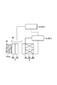
図1及び図2に示すように、羽根駆動装置1は、開口2Aを有するベース部材2と、開口2Aを遮蔽する羽根部材3,4と、駆動部5とを備えている。図示の例では、2枚の羽根部材3,4を用いて開口2Aを遮蔽する例を示しているが、1枚(単数)或いは3枚以上の複数の羽根部材によって開口2Aを遮蔽するものであってもよい。
As shown in FIGS. 1 and 2, the blade driving device 1 includes a
羽根部材3,4は、開口2Aとの重なり度合いに応じて開口2Aを遮蔽して、開口2Aの開口面積を可変にするものであり、ベース部材2に沿って摺動自在に支持されている。図示の例では、羽根部材3は、長孔3A,3B,3Cを備えており、これらにベース部材2に設けた突起部2B,2C,2Dがそれぞれ係合している。羽根部材4は、長孔4A,4B,4Cを備えており、これらにベース部材2に設けた突起部2D,2E,2Cがそれぞれ係合している。長孔3A〜4Cは全て同方向に延設されており、その方向が羽根部材3,4の摺動方向になっている。
The blade members 3 and 4 shield the
羽根部材3,4を摺動させる駆動部5は、動作部材6、弾性部材7、電磁石8、動作機構10を備えている。動作部材6は、マグネット6Aとマグネット支持部材6Bを備えており、ベース部材2上に摺動自在に支持されている。動作部材6は、ベース部材2に沿って、羽根部材3,4の全開又は全閉の一方に対応する第1位置から羽根部材3,4の全開又は全閉の他方に対応する第2位置まで摺動する。
The
弾性部材7は、図1及び図2に示した例ではコイルバネ7Aであり、一端側がベース部材2の支持枠2Fに固定され、他端側がマグネット支持部材6Bに固定されており、動作部材6を弾性力によって第1位置(図示の例では、羽根部材3,4の全閉に対応する位置)に向けて付勢する。
In the example shown in FIGS. 1 and 2, the
電磁石8は、コイル8Aと、コイル8Aが巻かれたコイルボビン8Bと、磁性体部材のヨーク8Cを備え、マグネット6Aに作用する電磁力により動作部材6を第2位置(図示の例では、羽根部材3,4の全開に対応する位置)に向けて付勢する。
The
動作機構10は、動作部材6の摺動を増幅して羽根部材3,4に伝えるものであり、連結レバー11と作動レバー12を備えている。連結レバー11は、一端側の連結部11Aが羽根部材3の端部に設けられた連結孔(長孔)3Dに連結しており、他端側の連結部11Bが羽根部材4の端部に設けられた連結孔(長孔)4Dに連結している。連結レバー11は、略中央に軸支部11Cを備えており、軸支部11Cがベース部材2の軸部2Gに軸支されている。
The
作動レバー12は、一端側の端部に設けられる連結部12Aが連結レバー11の連結孔(長孔)11Dに連結しており、他端側の端部に設けられる連結孔12Bが動作部材6の連結部6Cに連結されている。作動レバー12は、中央より連結孔12B側に軸支部12Cが設けられており、この軸支部12Cがベース部材2の軸部2Hに軸支されている。
The actuating
ベース部材2にはガイド部材13が設けられている。ガイド部材13は、作動レバー12における連結部12Aの揺動をガイドするガイド孔13Aと、動作部材6における連結部6Cの摺動をガイドするガイド孔13Bが設けられている。動作部材6が摺動して、連結部6Cがガイド孔13B内を摺動すると、それに応じて連結孔12Bにて連結部6Cに連結されている作動レバー12の一端側が回転し、その回転が増幅されて作動レバー12の他端側の連結部12Aがガイド孔13A内を摺動する。そして、増幅されて摺動する連結部12Aに連結孔11Dにて連結する連結レバー11が回転する。
The
図1は、羽根部材3,4によって開口2Aが全閉された状態を示している。図2は、羽根部材3,4が摺動して、開口2Aが全開された状態を示している。図1における動作部材6の状態を図3(a)に示している。この状態では、動作部材6は電磁石8側の第1位置に保持されている。図2における動作部材6の状態を図3(b)に示している。この状態では、動作部材6は弾性部材7側の第2位置に保持されている。
FIG. 1 shows a state in which the
ここで、第1位置は、電磁石8の無通電時における動作部材6の位置であり、コイルバネ(圧縮コイルバネ)7Aである弾性部材7の弾性力と、マグネット6Aとヨーク8Cとの磁気吸引力とによって、動作部材6は、電磁石8側に付勢されて、ストッパとなる枠体9の当接面9Aに当接保持されている。第2位置では、電磁石8のコイル8Aへの通電によって、マグネット6Aに電磁気反発力を作用させ、コイルバネ(圧縮コイルバネ)7Aである弾性部材7が最も圧縮された状態になるまで、動作部材6を電磁石8側とは逆側に摺動させている。
Here, the first position is the position of the
動作部材6は、電磁石8のコイル8Aへの通電電流を調整することで、図3(a)に示した第1位置と図3(b)に示した第2位置との間で摺動する。第1位置に向けて動作部材6が摺動すると、動作部材6の連結部6Cに連結孔12Bが連結している作動レバー12が軸部2Hの周りに回転して、連結部12Aが揺動し、連結部12Aに連結孔11Dにて連結している連結レバー11が軸部2G周りに回転して、連結レバー11の連結部11A,11Bに連結孔3D,4Dにて連結している羽根部材3,4を開口2Aが全閉になるように摺動させる。逆に、第2位置に向けて動作部材6が摺動すると、作動レバー12とそれに連結されている連結レバー11が前述と逆向きに回転して、羽根部材3,4を開口2Aが全開になるように摺動させる。そして、動作部材6の位置を第1位置と第2位置との間で調整することで、開口2Aの開口面積を適宜調整することができる。
The
図4に示した制御部を採用することで、動作部材6の位置を微細に調整して開口2Aの開口面積を制御することができる。図示の例では、動作部材6におけるマグネット6Aの位置を検出するホール素子などからなる検出部20と、検出部20の検出値に応じて電磁石8のコイル8Aへの通電電流の制御する制御部21を備えている。制御部21は、コイル8Aへの通電電流を可変にする駆動回路21Aと、駆動回路21Aを制御するCPU21Bなどによって構成することができる。CPU21Bは、フィードバックされる検出部20の検出値と入力される測光信号や画像信号によって駆動回路21Aを制御して、コイル8Aの通電電流を制御し、動作部材6の位置を所望の位置に調整する。
By adopting the control unit shown in FIG. 4, the position of the
ここで、コイル8Aが無通電の場合には、任意の位置にある動作部材6は、弾性部材7(コイルバネ7A)の弾性力によって第1位置に付勢され、第1位置に近づくとマグネット6Aとヨーク8Cとの磁気吸引力で第1位置に保持される。そして、コイル8Aへの通電は、マグネット6Aとヨーク8Cとの間の磁気吸引力を消失して逆に電磁気反発力が作用するように、電流の向き(コイルの巻方向)が設定されている。この電磁気反発力によって、通電電流を大きくすると、徐々に動作部材6は、第1位置から第2位置に向けて移動し、通電による電磁気反発力と動作部材6の第2位置に向けた変位で徐々に大きくなる弾性力とが釣り合ったところで、動作部材6は停止する。
Here, when the
これによると、動作部材6の移動変位に対してリニアに変化する弾性力と電磁気反発力が釣り合うように通電電流を制御するので、微細な動作部材6の変位に対して電流の変化レンジを広げて対応させることができ、高い解像度で制御することが可能になる。また、通電電流の上昇・降下に対して駆動力にヒステリシスが生じ難くなるので、これによっても動作部材6を高い解像度で制御することが可能になる。
According to this, since the energization current is controlled so that the elastic force and the electromagnetic repulsive force that linearly change with respect to the movement displacement of the
また、無通電時から通電初期の駆動力は、通電によってマグネット6Aとヨーク8Cとの磁気吸引力を消失させて電磁気反発力に変えるので、大きな通電電流を要すること無く、無通電状態で第1位置に保持されている動作部材6の移動を開始させることができる。これによって、従来技術と比較して、省電力での羽根駆動が可能になる。
Further, the driving force from the time of no energization to the initial energization is changed to an electromagnetic repulsive force by eliminating the magnetic attractive force between the
図5は駆動部の他の構成例を示している。この例では、弾性部材7として、巻きバネ7Bを用いるが、他の構成は前述した例と同様である。巻きバネ7Bは、連結レバー11の軸支部11Cに設けられ、連結レバー11の回転を図示左周りに付勢している。これによって、動作レバー12を介して連結される動作部材6が電磁石8側に付勢され、無通電時の羽根部材3,4の状態を全閉状態に保持している。
FIG. 5 shows another configuration example of the drive unit. In this example, the winding
この例においても、無通電時に当接面9Aに当接している動作部材6に対して、電磁石8のコイル8Aへの通電により、マグネット6Aに電磁気反発力を作用し、動作部材6を、図5(a)に示した第1位置から図5(b)に示した第2位置まで移動させる。このような巻きバネ7Bを用いることで、コイルバネ7Aの配置に要する動作部材6の摺動方向に沿ったスペースを削減することができ、装置の小型化が可能になる。
Also in this example, an electromagnetic repulsive force is applied to the
以上説明したように、本発明の実施形態に係る羽根駆動装置1は、省電力駆動で、開口2Aの開口面積の調整を高精度で微調整することができる。これによって、カメラユニットの絞り調整などに用いることで、高品質の画像を得ることが可能になる。また、各種の電子機器に用いることで、高精度の光量調整を低消費電力で行うことができる。
As described above, the blade driving device 1 according to the embodiment of the present invention can finely adjust the opening area of the
また、従来の電磁アクチュエータを用いる場合と比べて、動作部材6の高さを低くすることができるため、羽根駆動装置1全体を厚みを薄くすることができる。これにより、本発明の実施形態に係る羽根駆動装置1は薄型化が可能になり、この羽根駆動装置1を内部に搭載する電子機器は、羽根駆動装置1の設置占有スペースの省スペース化が可能になる。これにより、本発明の実施形態に係る羽根駆動装置1を備える電子機器は、電子機器自体の薄型化・小型化を実現することができると共に、高精度の光量調整を低消費電力で行うことができる。
Moreover, since the height of the
また、前述した実施形態では、動作部材6を第1位置に保持した状態で開口2Aが全閉となり、動作部材6を第2位置に保持した状態で開口2Aが全開になる例を示して説明したが、他の実施形態としては、動作部材6が第1位置で開口2Aが全開となり、動作部材6が第2位置で開口2Aが全閉となるようにしてもよい。
In the above-described embodiment, the
以上、本発明の実施の形態について図面を参照して詳述してきたが、具体的な構成はこれらの実施の形態に限られるものではなく、本発明の要旨を逸脱しない範囲の設計の変更等があっても本発明に含まれる。また、上述の各実施の形態は、その目的及び構成等に特に矛盾や問題がない限り、互いの技術を流用して組み合わせることが可能である。 As described above, the embodiments of the present invention have been described in detail with reference to the drawings. However, the specific configuration is not limited to these embodiments, and the design can be changed without departing from the scope of the present invention. Is included in the present invention. In addition, the above-described embodiments can be combined by utilizing each other's technology as long as there is no particular contradiction or problem in the purpose and configuration.
1:羽根駆動装置,
2:ベース部材,2A:開口,
2B,2C,2D,2E:突起部,2F:支持壁,2G,2H:軸部,
3,4:羽根部材,
3A,3B,3C,4A,4B,4C:長孔,3D,4D:連結孔,
5:駆動部,
6:動作部材,6A:マグネット,6B:マグネット支持部材,6C:連結部,
7:弾性部材,7A:コイルバネ,7B:巻きバネ,
8:電磁石,8A:コイル,8B:コイルボビン,8C:ヨーク,
9:枠体,9A:当接面,
10:動作機構,
11:連結レバー,11A,11B:連結部,
11C:軸支部,11D:連結孔,
12:作動レバー,12A:連結部,12B:連結孔,12C:軸支部,
13:ガイド部材,13A,13B:ガイド孔,
20:検出部(ホール素子),
21:制御部,21A:駆動回路,21B:CPU
1: blade drive device,
2: Base member, 2A: Opening,
2B, 2C, 2D, 2E: protrusion, 2F: support wall, 2G, 2H: shaft,
3,4: blade member,
3A, 3B, 3C, 4A, 4B, 4C: long hole, 3D, 4D: connecting hole,
5: Drive unit,
6: operation member, 6A: magnet, 6B: magnet support member, 6C: connecting portion,
7: elastic member, 7A: coil spring, 7B: winding spring,
8: electromagnet, 8A: coil, 8B: coil bobbin, 8C: yoke,
9: frame, 9A: contact surface,
10: operating mechanism,
11: connecting lever, 11A, 11B: connecting part,
11C: shaft support, 11D: connecting hole,
12: Actuating lever, 12A: Connecting part, 12B: Connecting hole, 12C: Shaft support part,
13: Guide member, 13A, 13B: Guide hole,
20: detection part (Hall element),
21: Control unit, 21A: Drive circuit, 21B: CPU
Claims (7)
前記駆動部は、
マグネットを備えて、前記ベース部材に沿って、前記羽根部材の全開又は全閉の一方に対応する第1位置から前記羽根部材の全開又は全閉の他方に対応する第2位置まで摺動する動作部材と、
前記動作部材を弾性力により前記第1位置に向けて付勢する弾性部材と、
前記マグネットに作用する電磁力により前記動作部材を前記第2位置に向けて付勢する電磁石とを備えることを特徴とする羽根駆動装置。 A base member having an opening; one or more blade members that slide along the base member to shield the opening; and a drive unit that slides the blade member,
The drive unit is
An operation including a magnet and sliding along the base member from a first position corresponding to one of the fully opened or fully closed blade members to a second position corresponding to the other of the fully opened or fully closed blade members. Members,
An elastic member that urges the operating member toward the first position by an elastic force;
A blade driving device comprising: an electromagnet that biases the operating member toward the second position by electromagnetic force acting on the magnet.
前記コイルへの無通電時には、前記マグネットと前記ヨークとの磁気吸引力により、前記動作部材は前記第1位置に保持され、
前記コイルへの通電時には、前記マグネットに作用する電磁気反発力により、前記動作部材を前記第1位置から第2位置に向けて摺動させることを特徴とする請求項1又は2記載の羽根駆動装置。 The electromagnet includes a coil and a yoke,
When no power is supplied to the coil, the operating member is held in the first position by the magnetic attractive force of the magnet and the yoke,
3. The blade driving device according to claim 1, wherein when the coil is energized, the operating member is slid from the first position toward the second position by an electromagnetic repulsive force acting on the magnet. .
前記検出部の検出値に応じて前記電磁石への通電電流を制御する制御部とを備えることを特徴とする請求項1〜4のいずれか1項に記載の羽根駆動装置。 A detection unit for detecting the position of the magnet;
The blade drive device according to any one of claims 1 to 4, further comprising a control unit that controls an energization current to the electromagnet according to a detection value of the detection unit.
Priority Applications (1)
| Application Number | Priority Date | Filing Date | Title |
|---|---|---|---|
| JP2016049948A JP2017167213A (en) | 2016-03-14 | 2016-03-14 | Blade driving device |
Applications Claiming Priority (1)
| Application Number | Priority Date | Filing Date | Title |
|---|---|---|---|
| JP2016049948A JP2017167213A (en) | 2016-03-14 | 2016-03-14 | Blade driving device |
Publications (1)
| Publication Number | Publication Date |
|---|---|
| JP2017167213A true JP2017167213A (en) | 2017-09-21 |
Family
ID=59908912
Family Applications (1)
| Application Number | Title | Priority Date | Filing Date |
|---|---|---|---|
| JP2016049948A Pending JP2017167213A (en) | 2016-03-14 | 2016-03-14 | Blade driving device |
Country Status (1)
| Country | Link |
|---|---|
| JP (1) | JP2017167213A (en) |
-
2016
- 2016-03-14 JP JP2016049948A patent/JP2017167213A/en active Pending
Similar Documents
| Publication | Publication Date | Title |
|---|---|---|
| JP6661599B2 (en) | Blade drive | |
| WO2016136931A1 (en) | Blade driving device | |
| JP5932295B2 (en) | LENS DRIVE UNIT, LENS DEVICE HAVING THE SAME, AND IMAGING DEVICE | |
| WO2018110247A1 (en) | Blade driving device | |
| JP2006333606A (en) | Electromagnetic drive device and light quantity adjusting device therewith | |
| US20100272429A1 (en) | Aperture-ring-and-shutter device | |
| JP5064809B2 (en) | Light control device | |
| KR101190390B1 (en) | Shutter device including return portion | |
| KR20110096391A (en) | Camera shutter device | |
| JP3122024U (en) | Swing type electromagnetic actuator and exposure condition switching device for camera | |
| JP2017167213A (en) | Blade driving device | |
| US8132973B2 (en) | Camera shutter | |
| KR20060095623A (en) | Shutter apparatus for camera | |
| US8491206B2 (en) | Light amount adjustment device capable of adjusting amount of light at high speed and with accuracy | |
| JP2002258348A (en) | Light quantity controller and electromagnetic driving device | |
| JP2004258062A (en) | Shutter driving device used also as diaphragm | |
| JP4901551B2 (en) | Blade driving device and imaging device | |
| JP2002341399A (en) | Light quantity controller | |
| JP3990779B2 (en) | Camera shutter | |
| JP5342179B2 (en) | Electromagnetic actuator and camera blade drive device | |
| JP5001060B2 (en) | Electromagnetic actuator and camera blade drive device | |
| JP2005080493A (en) | Drive unit, light quantity adjusting apparatus and photographic apparatus | |
| JP2007151354A (en) | Electromagnetic actuator and camera blade driving unit | |
| JP2017026835A (en) | Blade drive device and optical instrument having blade drive device provided | |
| JP2017116895A (en) | Focal plane shutter and imaging apparatus |
Legal Events
| Date | Code | Title | Description |
|---|---|---|---|
| A621 | Written request for application examination |
Free format text: JAPANESE INTERMEDIATE CODE: A621 Effective date: 20190125 |
|
| A977 | Report on retrieval |
Free format text: JAPANESE INTERMEDIATE CODE: A971007 Effective date: 20191125 |
|
| A131 | Notification of reasons for refusal |
Free format text: JAPANESE INTERMEDIATE CODE: A131 Effective date: 20191203 |
|
| A02 | Decision of refusal |
Free format text: JAPANESE INTERMEDIATE CODE: A02 Effective date: 20200602 |