JP2017166693A - Control system for hydrogen fuel replenishment station - Google Patents
Control system for hydrogen fuel replenishment station Download PDFInfo
- Publication number
- JP2017166693A JP2017166693A JP2017034806A JP2017034806A JP2017166693A JP 2017166693 A JP2017166693 A JP 2017166693A JP 2017034806 A JP2017034806 A JP 2017034806A JP 2017034806 A JP2017034806 A JP 2017034806A JP 2017166693 A JP2017166693 A JP 2017166693A
- Authority
- JP
- Japan
- Prior art keywords
- safety
- hydrogen
- controller
- refueling station
- hydrogen refueling
- Prior art date
- Legal status (The legal status is an assumption and is not a legal conclusion. Google has not performed a legal analysis and makes no representation as to the accuracy of the status listed.)
- Granted
Links
- 229910052739 hydrogen Inorganic materials 0.000 title claims abstract description 191
- 239000001257 hydrogen Substances 0.000 title claims abstract description 191
- UFHFLCQGNIYNRP-UHFFFAOYSA-N Hydrogen Chemical compound [H][H] UFHFLCQGNIYNRP-UHFFFAOYSA-N 0.000 title claims abstract description 183
- 239000000446 fuel Substances 0.000 title claims description 11
- 238000000034 method Methods 0.000 claims abstract description 188
- 230000008569 process Effects 0.000 claims abstract description 179
- 230000006870 function Effects 0.000 claims abstract description 71
- 238000012544 monitoring process Methods 0.000 claims abstract description 52
- 238000004886 process control Methods 0.000 claims abstract description 23
- 238000005259 measurement Methods 0.000 claims description 44
- 238000004891 communication Methods 0.000 claims description 30
- 230000008859 change Effects 0.000 claims description 24
- 238000001816 cooling Methods 0.000 claims description 18
- 238000011156 evaluation Methods 0.000 claims description 15
- 150000002431 hydrogen Chemical class 0.000 claims description 8
- 101100205030 Caenorhabditis elegans hars-1 gene Proteins 0.000 abstract description 39
- 230000007547 defect Effects 0.000 abstract description 4
- 238000011217 control strategy Methods 0.000 abstract description 2
- 101100339677 Arabidopsis thaliana HRS1 gene Proteins 0.000 description 17
- 101100129874 Saccharomyces cerevisiae (strain ATCC 204508 / S288c) PGD1 gene Proteins 0.000 description 17
- 101100129591 Schizosaccharomyces pombe (strain 972 / ATCC 24843) mcp6 gene Proteins 0.000 description 17
- 230000009471 action Effects 0.000 description 7
- 230000008901 benefit Effects 0.000 description 6
- 238000013461 design Methods 0.000 description 5
- 238000010586 diagram Methods 0.000 description 5
- 230000007257 malfunction Effects 0.000 description 5
- 238000009530 blood pressure measurement Methods 0.000 description 4
- 238000009529 body temperature measurement Methods 0.000 description 3
- 230000036541 health Effects 0.000 description 3
- 230000003993 interaction Effects 0.000 description 2
- 238000012423 maintenance Methods 0.000 description 2
- 230000002829 reductive effect Effects 0.000 description 2
- 238000012502 risk assessment Methods 0.000 description 2
- 208000032368 Device malfunction Diseases 0.000 description 1
- 230000004913 activation Effects 0.000 description 1
- 239000003570 air Substances 0.000 description 1
- 230000002950 deficient Effects 0.000 description 1
- 238000011161 development Methods 0.000 description 1
- 230000007613 environmental effect Effects 0.000 description 1
- 231100001261 hazardous Toxicity 0.000 description 1
- 238000001491 hyper Rayleigh scattering spectroscopy Methods 0.000 description 1
- 230000010354 integration Effects 0.000 description 1
- 230000002452 interceptive effect Effects 0.000 description 1
- 230000000670 limiting effect Effects 0.000 description 1
- 239000000463 material Substances 0.000 description 1
- 238000010606 normalization Methods 0.000 description 1
- 238000002360 preparation method Methods 0.000 description 1
- 238000012545 processing Methods 0.000 description 1
- 230000009467 reduction Effects 0.000 description 1
- 230000002441 reversible effect Effects 0.000 description 1
- 239000007858 starting material Substances 0.000 description 1
- 239000000725 suspension Substances 0.000 description 1
- 230000008685 targeting Effects 0.000 description 1
- 230000036962 time dependent Effects 0.000 description 1
- XLYOFNOQVPJJNP-UHFFFAOYSA-N water Substances O XLYOFNOQVPJJNP-UHFFFAOYSA-N 0.000 description 1
Images


Classifications
-
- G—PHYSICS
- G05—CONTROLLING; REGULATING
- G05D—SYSTEMS FOR CONTROLLING OR REGULATING NON-ELECTRIC VARIABLES
- G05D7/00—Control of flow
- G05D7/06—Control of flow characterised by the use of electric means
- G05D7/0617—Control of flow characterised by the use of electric means specially adapted for fluid materials
- G05D7/0629—Control of flow characterised by the use of electric means specially adapted for fluid materials characterised by the type of regulator means
- G05D7/0635—Control of flow characterised by the use of electric means specially adapted for fluid materials characterised by the type of regulator means by action on throttling means
-
- F—MECHANICAL ENGINEERING; LIGHTING; HEATING; WEAPONS; BLASTING
- F17—STORING OR DISTRIBUTING GASES OR LIQUIDS
- F17C—VESSELS FOR CONTAINING OR STORING COMPRESSED, LIQUEFIED OR SOLIDIFIED GASES; FIXED-CAPACITY GAS-HOLDERS; FILLING VESSELS WITH, OR DISCHARGING FROM VESSELS, COMPRESSED, LIQUEFIED, OR SOLIDIFIED GASES
- F17C7/00—Methods or apparatus for discharging liquefied, solidified, or compressed gases from pressure vessels, not covered by another subclass
-
- F—MECHANICAL ENGINEERING; LIGHTING; HEATING; WEAPONS; BLASTING
- F17—STORING OR DISTRIBUTING GASES OR LIQUIDS
- F17C—VESSELS FOR CONTAINING OR STORING COMPRESSED, LIQUEFIED OR SOLIDIFIED GASES; FIXED-CAPACITY GAS-HOLDERS; FILLING VESSELS WITH, OR DISCHARGING FROM VESSELS, COMPRESSED, LIQUEFIED, OR SOLIDIFIED GASES
- F17C5/00—Methods or apparatus for filling containers with liquefied, solidified, or compressed gases under pressures
- F17C5/002—Automated filling apparatus
- F17C5/007—Automated filling apparatus for individual gas tanks or containers, e.g. in vehicles
-
- F—MECHANICAL ENGINEERING; LIGHTING; HEATING; WEAPONS; BLASTING
- F17—STORING OR DISTRIBUTING GASES OR LIQUIDS
- F17C—VESSELS FOR CONTAINING OR STORING COMPRESSED, LIQUEFIED OR SOLIDIFIED GASES; FIXED-CAPACITY GAS-HOLDERS; FILLING VESSELS WITH, OR DISCHARGING FROM VESSELS, COMPRESSED, LIQUEFIED, OR SOLIDIFIED GASES
- F17C13/00—Details of vessels or of the filling or discharging of vessels
- F17C13/02—Special adaptations of indicating, measuring, or monitoring equipment
- F17C13/025—Special adaptations of indicating, measuring, or monitoring equipment having the pressure as the parameter
-
- F—MECHANICAL ENGINEERING; LIGHTING; HEATING; WEAPONS; BLASTING
- F17—STORING OR DISTRIBUTING GASES OR LIQUIDS
- F17C—VESSELS FOR CONTAINING OR STORING COMPRESSED, LIQUEFIED OR SOLIDIFIED GASES; FIXED-CAPACITY GAS-HOLDERS; FILLING VESSELS WITH, OR DISCHARGING FROM VESSELS, COMPRESSED, LIQUEFIED, OR SOLIDIFIED GASES
- F17C13/00—Details of vessels or of the filling or discharging of vessels
- F17C13/02—Special adaptations of indicating, measuring, or monitoring equipment
- F17C13/026—Special adaptations of indicating, measuring, or monitoring equipment having the temperature as the parameter
-
- F—MECHANICAL ENGINEERING; LIGHTING; HEATING; WEAPONS; BLASTING
- F17—STORING OR DISTRIBUTING GASES OR LIQUIDS
- F17C—VESSELS FOR CONTAINING OR STORING COMPRESSED, LIQUEFIED OR SOLIDIFIED GASES; FIXED-CAPACITY GAS-HOLDERS; FILLING VESSELS WITH, OR DISCHARGING FROM VESSELS, COMPRESSED, LIQUEFIED, OR SOLIDIFIED GASES
- F17C13/00—Details of vessels or of the filling or discharging of vessels
- F17C13/04—Arrangement or mounting of valves
-
- F—MECHANICAL ENGINEERING; LIGHTING; HEATING; WEAPONS; BLASTING
- F17—STORING OR DISTRIBUTING GASES OR LIQUIDS
- F17C—VESSELS FOR CONTAINING OR STORING COMPRESSED, LIQUEFIED OR SOLIDIFIED GASES; FIXED-CAPACITY GAS-HOLDERS; FILLING VESSELS WITH, OR DISCHARGING FROM VESSELS, COMPRESSED, LIQUEFIED, OR SOLIDIFIED GASES
- F17C5/00—Methods or apparatus for filling containers with liquefied, solidified, or compressed gases under pressures
- F17C5/06—Methods or apparatus for filling containers with liquefied, solidified, or compressed gases under pressures for filling with compressed gases
-
- G—PHYSICS
- G05—CONTROLLING; REGULATING
- G05B—CONTROL OR REGULATING SYSTEMS IN GENERAL; FUNCTIONAL ELEMENTS OF SUCH SYSTEMS; MONITORING OR TESTING ARRANGEMENTS FOR SUCH SYSTEMS OR ELEMENTS
- G05B9/00—Safety arrangements
- G05B9/02—Safety arrangements electric
-
- B—PERFORMING OPERATIONS; TRANSPORTING
- B60—VEHICLES IN GENERAL
- B60K—ARRANGEMENT OR MOUNTING OF PROPULSION UNITS OR OF TRANSMISSIONS IN VEHICLES; ARRANGEMENT OR MOUNTING OF PLURAL DIVERSE PRIME-MOVERS IN VEHICLES; AUXILIARY DRIVES FOR VEHICLES; INSTRUMENTATION OR DASHBOARDS FOR VEHICLES; ARRANGEMENTS IN CONNECTION WITH COOLING, AIR INTAKE, GAS EXHAUST OR FUEL SUPPLY OF PROPULSION UNITS IN VEHICLES
- B60K15/00—Arrangement in connection with fuel supply of combustion engines or other fuel consuming energy converters, e.g. fuel cells; Mounting or construction of fuel tanks
- B60K15/03—Fuel tanks
- B60K2015/03309—Tanks specially adapted for particular fuels
- B60K2015/03315—Tanks specially adapted for particular fuels for hydrogen
-
- F—MECHANICAL ENGINEERING; LIGHTING; HEATING; WEAPONS; BLASTING
- F17—STORING OR DISTRIBUTING GASES OR LIQUIDS
- F17C—VESSELS FOR CONTAINING OR STORING COMPRESSED, LIQUEFIED OR SOLIDIFIED GASES; FIXED-CAPACITY GAS-HOLDERS; FILLING VESSELS WITH, OR DISCHARGING FROM VESSELS, COMPRESSED, LIQUEFIED, OR SOLIDIFIED GASES
- F17C2221/00—Handled fluid, in particular type of fluid
- F17C2221/01—Pure fluids
- F17C2221/012—Hydrogen
-
- F—MECHANICAL ENGINEERING; LIGHTING; HEATING; WEAPONS; BLASTING
- F17—STORING OR DISTRIBUTING GASES OR LIQUIDS
- F17C—VESSELS FOR CONTAINING OR STORING COMPRESSED, LIQUEFIED OR SOLIDIFIED GASES; FIXED-CAPACITY GAS-HOLDERS; FILLING VESSELS WITH, OR DISCHARGING FROM VESSELS, COMPRESSED, LIQUEFIED, OR SOLIDIFIED GASES
- F17C2223/00—Handled fluid before transfer, i.e. state of fluid when stored in the vessel or before transfer from the vessel
- F17C2223/03—Handled fluid before transfer, i.e. state of fluid when stored in the vessel or before transfer from the vessel characterised by the pressure level
- F17C2223/036—Very high pressure (>80 bar)
-
- F—MECHANICAL ENGINEERING; LIGHTING; HEATING; WEAPONS; BLASTING
- F17—STORING OR DISTRIBUTING GASES OR LIQUIDS
- F17C—VESSELS FOR CONTAINING OR STORING COMPRESSED, LIQUEFIED OR SOLIDIFIED GASES; FIXED-CAPACITY GAS-HOLDERS; FILLING VESSELS WITH, OR DISCHARGING FROM VESSELS, COMPRESSED, LIQUEFIED, OR SOLIDIFIED GASES
- F17C2227/00—Transfer of fluids, i.e. method or means for transferring the fluid; Heat exchange with the fluid
- F17C2227/01—Propulsion of the fluid
- F17C2227/0128—Propulsion of the fluid with pumps or compressors
- F17C2227/0157—Compressors
-
- F—MECHANICAL ENGINEERING; LIGHTING; HEATING; WEAPONS; BLASTING
- F17—STORING OR DISTRIBUTING GASES OR LIQUIDS
- F17C—VESSELS FOR CONTAINING OR STORING COMPRESSED, LIQUEFIED OR SOLIDIFIED GASES; FIXED-CAPACITY GAS-HOLDERS; FILLING VESSELS WITH, OR DISCHARGING FROM VESSELS, COMPRESSED, LIQUEFIED, OR SOLIDIFIED GASES
- F17C2227/00—Transfer of fluids, i.e. method or means for transferring the fluid; Heat exchange with the fluid
- F17C2227/03—Heat exchange with the fluid
- F17C2227/0337—Heat exchange with the fluid by cooling
-
- F—MECHANICAL ENGINEERING; LIGHTING; HEATING; WEAPONS; BLASTING
- F17—STORING OR DISTRIBUTING GASES OR LIQUIDS
- F17C—VESSELS FOR CONTAINING OR STORING COMPRESSED, LIQUEFIED OR SOLIDIFIED GASES; FIXED-CAPACITY GAS-HOLDERS; FILLING VESSELS WITH, OR DISCHARGING FROM VESSELS, COMPRESSED, LIQUEFIED, OR SOLIDIFIED GASES
- F17C2250/00—Accessories; Control means; Indicating, measuring or monitoring of parameters
- F17C2250/03—Control means
- F17C2250/032—Control means using computers
-
- F—MECHANICAL ENGINEERING; LIGHTING; HEATING; WEAPONS; BLASTING
- F17—STORING OR DISTRIBUTING GASES OR LIQUIDS
- F17C—VESSELS FOR CONTAINING OR STORING COMPRESSED, LIQUEFIED OR SOLIDIFIED GASES; FIXED-CAPACITY GAS-HOLDERS; FILLING VESSELS WITH, OR DISCHARGING FROM VESSELS, COMPRESSED, LIQUEFIED, OR SOLIDIFIED GASES
- F17C2250/00—Accessories; Control means; Indicating, measuring or monitoring of parameters
- F17C2250/04—Indicating or measuring of parameters as input values
- F17C2250/0404—Parameters indicated or measured
- F17C2250/043—Pressure
-
- F—MECHANICAL ENGINEERING; LIGHTING; HEATING; WEAPONS; BLASTING
- F17—STORING OR DISTRIBUTING GASES OR LIQUIDS
- F17C—VESSELS FOR CONTAINING OR STORING COMPRESSED, LIQUEFIED OR SOLIDIFIED GASES; FIXED-CAPACITY GAS-HOLDERS; FILLING VESSELS WITH, OR DISCHARGING FROM VESSELS, COMPRESSED, LIQUEFIED, OR SOLIDIFIED GASES
- F17C2250/00—Accessories; Control means; Indicating, measuring or monitoring of parameters
- F17C2250/04—Indicating or measuring of parameters as input values
- F17C2250/0404—Parameters indicated or measured
- F17C2250/0439—Temperature
-
- F—MECHANICAL ENGINEERING; LIGHTING; HEATING; WEAPONS; BLASTING
- F17—STORING OR DISTRIBUTING GASES OR LIQUIDS
- F17C—VESSELS FOR CONTAINING OR STORING COMPRESSED, LIQUEFIED OR SOLIDIFIED GASES; FIXED-CAPACITY GAS-HOLDERS; FILLING VESSELS WITH, OR DISCHARGING FROM VESSELS, COMPRESSED, LIQUEFIED, OR SOLIDIFIED GASES
- F17C2250/00—Accessories; Control means; Indicating, measuring or monitoring of parameters
- F17C2250/04—Indicating or measuring of parameters as input values
- F17C2250/0404—Parameters indicated or measured
- F17C2250/0443—Flow or movement of content
-
- F—MECHANICAL ENGINEERING; LIGHTING; HEATING; WEAPONS; BLASTING
- F17—STORING OR DISTRIBUTING GASES OR LIQUIDS
- F17C—VESSELS FOR CONTAINING OR STORING COMPRESSED, LIQUEFIED OR SOLIDIFIED GASES; FIXED-CAPACITY GAS-HOLDERS; FILLING VESSELS WITH, OR DISCHARGING FROM VESSELS, COMPRESSED, LIQUEFIED, OR SOLIDIFIED GASES
- F17C2250/00—Accessories; Control means; Indicating, measuring or monitoring of parameters
- F17C2250/04—Indicating or measuring of parameters as input values
- F17C2250/0404—Parameters indicated or measured
- F17C2250/0478—Position or presence
-
- F—MECHANICAL ENGINEERING; LIGHTING; HEATING; WEAPONS; BLASTING
- F17—STORING OR DISTRIBUTING GASES OR LIQUIDS
- F17C—VESSELS FOR CONTAINING OR STORING COMPRESSED, LIQUEFIED OR SOLIDIFIED GASES; FIXED-CAPACITY GAS-HOLDERS; FILLING VESSELS WITH, OR DISCHARGING FROM VESSELS, COMPRESSED, LIQUEFIED, OR SOLIDIFIED GASES
- F17C2250/00—Accessories; Control means; Indicating, measuring or monitoring of parameters
- F17C2250/06—Controlling or regulating of parameters as output values
- F17C2250/0605—Parameters
- F17C2250/0626—Pressure
-
- F—MECHANICAL ENGINEERING; LIGHTING; HEATING; WEAPONS; BLASTING
- F17—STORING OR DISTRIBUTING GASES OR LIQUIDS
- F17C—VESSELS FOR CONTAINING OR STORING COMPRESSED, LIQUEFIED OR SOLIDIFIED GASES; FIXED-CAPACITY GAS-HOLDERS; FILLING VESSELS WITH, OR DISCHARGING FROM VESSELS, COMPRESSED, LIQUEFIED, OR SOLIDIFIED GASES
- F17C2250/00—Accessories; Control means; Indicating, measuring or monitoring of parameters
- F17C2250/06—Controlling or regulating of parameters as output values
- F17C2250/0605—Parameters
- F17C2250/0631—Temperature
-
- F—MECHANICAL ENGINEERING; LIGHTING; HEATING; WEAPONS; BLASTING
- F17—STORING OR DISTRIBUTING GASES OR LIQUIDS
- F17C—VESSELS FOR CONTAINING OR STORING COMPRESSED, LIQUEFIED OR SOLIDIFIED GASES; FIXED-CAPACITY GAS-HOLDERS; FILLING VESSELS WITH, OR DISCHARGING FROM VESSELS, COMPRESSED, LIQUEFIED, OR SOLIDIFIED GASES
- F17C2250/00—Accessories; Control means; Indicating, measuring or monitoring of parameters
- F17C2250/06—Controlling or regulating of parameters as output values
- F17C2250/0605—Parameters
- F17C2250/0636—Flow or movement of content
-
- F—MECHANICAL ENGINEERING; LIGHTING; HEATING; WEAPONS; BLASTING
- F17—STORING OR DISTRIBUTING GASES OR LIQUIDS
- F17C—VESSELS FOR CONTAINING OR STORING COMPRESSED, LIQUEFIED OR SOLIDIFIED GASES; FIXED-CAPACITY GAS-HOLDERS; FILLING VESSELS WITH, OR DISCHARGING FROM VESSELS, COMPRESSED, LIQUEFIED, OR SOLIDIFIED GASES
- F17C2250/00—Accessories; Control means; Indicating, measuring or monitoring of parameters
- F17C2250/06—Controlling or regulating of parameters as output values
- F17C2250/0689—Methods for controlling or regulating
- F17C2250/0694—Methods for controlling or regulating with calculations
-
- F—MECHANICAL ENGINEERING; LIGHTING; HEATING; WEAPONS; BLASTING
- F17—STORING OR DISTRIBUTING GASES OR LIQUIDS
- F17C—VESSELS FOR CONTAINING OR STORING COMPRESSED, LIQUEFIED OR SOLIDIFIED GASES; FIXED-CAPACITY GAS-HOLDERS; FILLING VESSELS WITH, OR DISCHARGING FROM VESSELS, COMPRESSED, LIQUEFIED, OR SOLIDIFIED GASES
- F17C2260/00—Purposes of gas storage and gas handling
- F17C2260/02—Improving properties related to fluid or fluid transfer
-
- F—MECHANICAL ENGINEERING; LIGHTING; HEATING; WEAPONS; BLASTING
- F17—STORING OR DISTRIBUTING GASES OR LIQUIDS
- F17C—VESSELS FOR CONTAINING OR STORING COMPRESSED, LIQUEFIED OR SOLIDIFIED GASES; FIXED-CAPACITY GAS-HOLDERS; FILLING VESSELS WITH, OR DISCHARGING FROM VESSELS, COMPRESSED, LIQUEFIED, OR SOLIDIFIED GASES
- F17C2260/00—Purposes of gas storage and gas handling
- F17C2260/04—Reducing risks and environmental impact
- F17C2260/042—Reducing risk of explosion
-
- F—MECHANICAL ENGINEERING; LIGHTING; HEATING; WEAPONS; BLASTING
- F17—STORING OR DISTRIBUTING GASES OR LIQUIDS
- F17C—VESSELS FOR CONTAINING OR STORING COMPRESSED, LIQUEFIED OR SOLIDIFIED GASES; FIXED-CAPACITY GAS-HOLDERS; FILLING VESSELS WITH, OR DISCHARGING FROM VESSELS, COMPRESSED, LIQUEFIED, OR SOLIDIFIED GASES
- F17C2265/00—Effects achieved by gas storage or gas handling
- F17C2265/06—Fluid distribution
- F17C2265/061—Fluid distribution for supply of supplying vehicles
-
- F—MECHANICAL ENGINEERING; LIGHTING; HEATING; WEAPONS; BLASTING
- F17—STORING OR DISTRIBUTING GASES OR LIQUIDS
- F17C—VESSELS FOR CONTAINING OR STORING COMPRESSED, LIQUEFIED OR SOLIDIFIED GASES; FIXED-CAPACITY GAS-HOLDERS; FILLING VESSELS WITH, OR DISCHARGING FROM VESSELS, COMPRESSED, LIQUEFIED, OR SOLIDIFIED GASES
- F17C2265/00—Effects achieved by gas storage or gas handling
- F17C2265/06—Fluid distribution
- F17C2265/065—Fluid distribution for refueling vehicle fuel tanks
-
- F—MECHANICAL ENGINEERING; LIGHTING; HEATING; WEAPONS; BLASTING
- F17—STORING OR DISTRIBUTING GASES OR LIQUIDS
- F17C—VESSELS FOR CONTAINING OR STORING COMPRESSED, LIQUEFIED OR SOLIDIFIED GASES; FIXED-CAPACITY GAS-HOLDERS; FILLING VESSELS WITH, OR DISCHARGING FROM VESSELS, COMPRESSED, LIQUEFIED, OR SOLIDIFIED GASES
- F17C2270/00—Applications
- F17C2270/01—Applications for fluid transport or storage
- F17C2270/0134—Applications for fluid transport or storage placed above the ground
- F17C2270/0139—Fuel stations
-
- F—MECHANICAL ENGINEERING; LIGHTING; HEATING; WEAPONS; BLASTING
- F17—STORING OR DISTRIBUTING GASES OR LIQUIDS
- F17C—VESSELS FOR CONTAINING OR STORING COMPRESSED, LIQUEFIED OR SOLIDIFIED GASES; FIXED-CAPACITY GAS-HOLDERS; FILLING VESSELS WITH, OR DISCHARGING FROM VESSELS, COMPRESSED, LIQUEFIED, OR SOLIDIFIED GASES
- F17C2270/00—Applications
- F17C2270/01—Applications for fluid transport or storage
- F17C2270/0165—Applications for fluid transport or storage on the road
- F17C2270/0168—Applications for fluid transport or storage on the road by vehicles
-
- Y—GENERAL TAGGING OF NEW TECHNOLOGICAL DEVELOPMENTS; GENERAL TAGGING OF CROSS-SECTIONAL TECHNOLOGIES SPANNING OVER SEVERAL SECTIONS OF THE IPC; TECHNICAL SUBJECTS COVERED BY FORMER USPC CROSS-REFERENCE ART COLLECTIONS [XRACs] AND DIGESTS
- Y02—TECHNOLOGIES OR APPLICATIONS FOR MITIGATION OR ADAPTATION AGAINST CLIMATE CHANGE
- Y02E—REDUCTION OF GREENHOUSE GAS [GHG] EMISSIONS, RELATED TO ENERGY GENERATION, TRANSMISSION OR DISTRIBUTION
- Y02E60/00—Enabling technologies; Technologies with a potential or indirect contribution to GHG emissions mitigation
- Y02E60/30—Hydrogen technology
- Y02E60/32—Hydrogen storage
Abstract
Description
本発明は、水素燃料補給ステーション用制御システムと、そのような制御システムを有する水素燃料補給ステーションの制御方法に関する。 The present invention relates to a control system for a hydrogen refueling station and a method for controlling a hydrogen refueling station having such a control system.
水素燃料補給ステーション(Hydrogen Refuelling Station(HRS))の数が増加し始めており、HRS製造会社の関心は、安全性を損なうことなく、個々のHRSの価格を切り下げることにある。 As the number of Hydrogen Refueling Stations (HRS) has begun to increase, HRS manufacturers are interested in cutting down the price of individual HRSs without compromising safety.
HRS用制御システムは特許文献1に記載されている。この制御システムのアーキテクチャは、制御マネージャと、複数のサブシステムマネージャに依存している。マスタ制御マネージャは、複数の専用サブシステムマネージャを介して浄化水素生成器の制御を管理する。従って、燃料、水、空気などを制御するサブシステムは、マスタ制御マネージャに通信可能に取り付けられているサブシステムコントローラにより、分散的な方法で制御される。
A control system for HRS is described in
特許文献1は、HRSの制御に関連してなされた安全性を考慮した例である。しかし、これらの考慮は、システムレベルでなされており、従って、実現、システムレベルで起こる欠陥、欠陥状況における制御戦略などのような広い範囲の問題を解決しない。
本発明の目的は、これらの問題を克服することである。従って、本発明は、車両の容器に水素を充填するためのHRSに関し、HRSは、水素供給源と、車両の容器に接続可能な水素取出し口と、プロセスコントローラ、複数のプロセス測定装置、最終プロセス要素、及びHRSの作動の監視と制御を容易にする、関連する複数の基本プロセス制御機能を備える基本プロセス制御システムと、を備え、HRSは更に、安全コントローラと、複数の安全測定装置と、複数の最終安全要素と、関連する複数の安全計装機能と、を備える安全計装システムを備え、最終プロセス要素と最終安全要素の少なくとも1つは、関連するプロセスコントローラ、又は、関連する安全コントローラそれぞれの制御のもとで、HRSの作動のトリップを容易にすることを特徴とする。 The object of the present invention is to overcome these problems. Accordingly, the present invention relates to an HRS for filling a vehicle container with hydrogen, the HRS comprising a hydrogen supply source, a hydrogen outlet connectable to the vehicle container, a process controller, a plurality of process measurement devices, and a final process. And a basic process control system with a plurality of related basic process control functions that facilitate monitoring and control of HRS operation, the HRS further comprising a safety controller, a plurality of safety measuring devices, a plurality of A final safety element and a plurality of related safety instrumentation functions, wherein at least one of the final process element and the final safety element is an associated process controller or an associated safety controller, respectively. This makes it easy to trip the operation of the HRS under the control of the above.
HRSの作動のトリップは、プロセスコントローラによるプロセス制御機能の実行により行われるのが好適であり、もし、何らかの理由でトリップが起こらない場合は、HRSの作動は、安全コントローラによる安全計装機能の実行によりトリップされると有利である。 The trip of operation of the HRS is preferably performed by execution of the process control function by the process controller, and if for some reason the trip does not occur, the operation of the HRS is performed by the safety controller. It is advantageous to be tripped by.
基本プロセス制御機能と安全計装機能は、好ましくは、安全コントローラのマイクロプロセッサにより実行されるプログラムコードであり、プロセス制御機能は、好ましくは、プロセスコントローラにより実行されるプログラムコードである。 The basic process control function and the safety instrumentation function are preferably program code executed by the microprocessor of the safety controller, and the process control function is preferably program code executed by the process controller.
HRSのトリップ作動は、好ましくは、HRSの作動の即時停止という結果になり、例えば、危険な状況が検出された場合は、燃料補給プロセスは即時停止され、冷却システム、コンプレッサなどを停止する。危険な状況は、例えば、高すぎる圧力又は温度、低すぎる圧力又は温度、漏洩、火気などである。 The HRS trip operation preferably results in an immediate stop of the HRS operation, for example, if a dangerous situation is detected, the refueling process is immediately stopped and the cooling system, compressor, etc. are stopped. Hazardous situations are, for example, pressures or temperatures that are too high, pressures or temperatures that are too low, leaks, fire, etc.
HRSの作動を停止できる最終要素は、好ましくは、ノズルへの水素流路における水素の流量を停止する弁、又は、煙突を介して、水素放出を容易にする弁である。最終要素は、制御信号に反応することにより画定され、最終要素の制御の結果の例としては、水素流量を停止し、水素を煙突から外に安全に誘導すること、コンプレッサをトリップすることなどを挙げることができる。 The final element that can stop the operation of the HRS is preferably a valve that stops the flow of hydrogen in the hydrogen flow path to the nozzle, or a valve that facilitates hydrogen release via a chimney. The final element is defined by reacting to the control signal, and examples of final element control results include stopping the hydrogen flow rate, safely guiding hydrogen out of the chimney, tripping the compressor, etc. Can be mentioned.
本発明の実施の形態によれば、基本プロセス制御機能の数は、安全計装機能の数よりも多い。安全に関連する、すなわち、危険な状況に繋がる可能性のある基本プロセス制御機能のみが、安全計装システムにより監視されると好適である。そのため、基本プロセス制御機能と同じ数の安全計装機能は必要でない。 According to an embodiment of the present invention, the number of basic process control functions is greater than the number of safety instrumented functions. Only basic process control functions that are relevant to safety, i.e. that can lead to dangerous situations, are preferably monitored by the safety instrumented system. Therefore, the same number of safety instrumented functions as basic process control functions are not necessary.
本発明の実施の形態によれば、安全計装機能は、基本プロセス制御機能へ入力を提供する。 According to an embodiment of the invention, the safety instrumentation function provides input to the basic process control function.
本発明の実施の形態によれば、入力は、HRSの作動のモードを変更、好ましくは、HRSの作動を停止するために使用される。これは、安全計装機能がその入力(の安全性)を評価し、その結果が、危険な状況が起きている、又は、起こりそうであるという状況においては利点である。そのため、安全計装機能は、プロセスコントローラに、HRSの作動を停止するように依頼することができ、及び/又は、その最終安全要素により、HRSの作動の停止を開始することができる。 According to an embodiment of the invention, the input is used to change the mode of operation of the HRS, preferably to stop the operation of the HRS. This is an advantage in situations where the safety instrumented function evaluates its input and the result is or is likely to be a dangerous situation. As such, the safety instrumentation function can ask the process controller to stop the operation of the HRS and / or its final safety element can initiate the stop of the operation of the HRS.
作動のモードの停止又は変更は、好ましくは、危険な状況がエスカレートすることを防止するために、可能な限り速く行われる。 Stopping or changing the mode of operation is preferably done as fast as possible to prevent dangerous situations from escalating.
本発明の実施の形態によれば、安全コントローラ及びプロセスコントローラは、独立したマイクロプロセッサを備える。コントローラが完全に独立しているという点において利点がある。 According to an embodiment of the invention, the safety controller and the process controller comprise independent microprocessors. There is an advantage in that the controller is completely independent.
本発明の実施の形態によれば、車両の容器に水素を充填するときの水素の温度は、マイナス20℃より低く、好ましくは、マイナス30℃より低く、最も好ましくは、マイナス33℃とマイナス40℃との間である。 According to an embodiment of the present invention, the temperature of hydrogen when filling a vehicle container with hydrogen is less than minus 20 ° C, preferably less than minus 30 ° C, and most preferably minus 33 ° C and minus 40 ° C. Between ℃.
本発明の実施の形態によれば、車両の容器へ燃料補給する端部側での水素の圧力は、500バール以上であり、好ましくは、750バール以上であり、最も好ましくは、875バール以下である。燃料補給の開始圧力は、好ましくは、HRSディスペンサモジュールに接続するときの容器における圧力に依存して、1から700バールである。好ましくは、燃料補給の端部側における圧力は、ホース及びノズルを含むHRS構成要素が、HRSディスペンサを車両に接続する圧力に制限されるべきである。可能な限り多くの水素を車両容器に燃料補給するためには、端部側の圧力は、好ましくは、800と875バールの間である。 According to an embodiment of the present invention, the hydrogen pressure on the end side for refueling the container of the vehicle is 500 bar or more, preferably 750 bar or more, most preferably 875 bar or less. is there. The refueling starting pressure is preferably between 1 and 700 bar, depending on the pressure in the container when connected to the HRS dispenser module. Preferably, the pressure on the refueling end side should be limited to the pressure at which the HRS components including the hose and nozzle connect the HRS dispenser to the vehicle. In order to refuel the vehicle container with as much hydrogen as possible, the pressure on the end side is preferably between 800 and 875 bar.
本発明の実施の形態によれば、HRSは、車両の容器に水素を充填することを容易にし、HRSは、水素供給源と、車両の容器に接続可能な水素取出し口と、HRSの作動の監視と制御をするプロセスコントローラと、を備え、第1のパラメータの値は、プロセス測定装置により測定され、HRSを制御するプロセスコントローラへの入力として使用され、プロセスコントローラによるHRSの制御は、第1のパラメータのプロセス評価に基づいてHRSの作動を停止することを含み、HRSは、HRSの複数のパラメータを監視し、少なくとも部分的には、HRSを制御するように構成されている安全コントローラを更に備え、第1のパラメータの値はまた、安全測定装置によっても測定され、安全コントローラへの入力として使用され、安全コントローラは、第1のパラメータの安全評価を行い、安全コントローラの制御は、HRSの作動の通常モードから、作動の非通常モードへの変更を、第1のパラメータの値の安全評価に基づいて、最終安全要素の状態を変更することにより容易にする。 According to an embodiment of the present invention, the HRS facilitates filling a vehicle container with hydrogen, the HRS includes a hydrogen supply source, a hydrogen outlet that can be connected to the vehicle container, and the operation of the HRS. A process controller that monitors and controls, wherein the value of the first parameter is measured by the process measurement device and used as an input to the process controller that controls the HRS. Deactivating the HRS based on a process assessment of the parameters of the HRS, wherein the HRS further monitors a plurality of parameters of the HRS and further includes a safety controller configured to control the HRS at least in part. The value of the first parameter is also measured by the safety measuring device and used as an input to the safety controller, All controllers perform a safety evaluation of the first parameter, and the control of the safety controller changes the normal mode of operation of the HRS from the non-normal mode of operation based on the safety evaluation of the value of the first parameter. Facilitate by changing the state of the final safety element.
本発明のHRSは、例えば、ソフトウェアによる構成要素における故障の結果としてのHRSにおける深刻な事故のリスクを削減するという点において利点がある。これは、安全コントローラにより提供される上位の監視、又は、プロセスコントローラにより行われる制御及びプロセスコントローラを支配して作動のモードを変更する安全コントローラの権利によるためである。従って、HRSの制御は、プロセスコントローラにより行われ、作動パラメータの値が限界を外れ、プロセスコントローラが行動を取らない場合のみ、安全コントローラは、HRSの制御を受け継ぎ、安全モードにする(HRSのトリップ)ことを確実にする。すなわち、通常作動の間、安全コントローラは、HRSの制御に干渉せずに、HRSの作動を監視するのみである。 The HRS of the present invention is advantageous in that it reduces the risk of serious accidents in HRS as a result of, for example, software component failure. This is due to the superior monitoring provided by the safety controller, or the control performed by the process controller and the right of the safety controller to control the process controller and change the mode of operation. Therefore, the control of the HRS is performed by the process controller, and only when the value of the operating parameter is out of the limit and the process controller takes no action, the safety controller takes over the control of the HRS and enters the safety mode (HRS trip). ) Make sure. That is, during normal operation, the safety controller only monitors the operation of the HRS without interfering with the control of the HRS.
水素供給源は、好ましくは、弁を介して、HRSへの水素の流量を可能にする水素ストレージである。水素ストレージは、HRSの一部(内部ストレージ)又は、HRSの外部に位置するストレージである。或いは、水素取入れ口は、水素供給ネットワークなどに接続できる。 The hydrogen source is preferably hydrogen storage that allows the flow of hydrogen to the HRS via a valve. Hydrogen storage is a part of the HRS (internal storage) or storage located outside the HRS. Alternatively, the hydrogen inlet can be connected to a hydrogen supply network or the like.
監視はまた、制御システムのコントローラ、特には、安全コントローラにおいて行われる計算も含むことができる。従って、内部比較、集積、及び任意の種類の計算もまたパラメータの値という結果になり、このパラメータの値は、プロセス又は安全コントローラの何れかによるHRSの制御に使用できる。監視が単に計算の場合は、第1の及び第2の測定装置は、コントローラのデータプロセッサであることがよくある。好ましくは、ここで言及されるコントローラは、安全コントローラ及びプロセスコントローラであるが、しかし、必要であれば、追加コントローラを、プロセス及び安全コントローラがそれぞれの機能を行うことをサポートすることにおける異なる目的で使用できる。 Monitoring can also include calculations performed at the controller of the control system, in particular the safety controller. Thus, internal comparison, integration, and any type of calculation also result in a parameter value that can be used to control the HRS by either the process or the safety controller. If the monitoring is simply a calculation, the first and second measuring devices are often controller data processors. Preferably, the controllers mentioned here are safety controllers and process controllers, but if necessary, additional controllers may be used for different purposes in supporting the process and safety controllers to perform their respective functions. Can be used.
第1の及び第2の測定装置は、HRSの略同じ位置において同じパラメータを測定する同一の装置であってよい。測定装置の例としては(計算のための上記のプロセッサの他に)、圧力、温度、流量、時間、弁の位置(例えば、開/閉)などを監視するためのトランスデューサを挙げることができる。 The first and second measurement devices may be the same device that measures the same parameter at substantially the same location of the HRS. Examples of measuring devices (in addition to the processor described above for calculation) can include transducers for monitoring pressure, temperature, flow rate, time, valve position (eg, open / closed), and the like.
測定装置により測定されるパラメータ(第1の、第2の、・・・第Nパラメータ)の値は、直接、又は間接的に、流量、圧力、温度、水素濃度などを表わす、例えば、「1」又は「0」(例えば、値は「オン」又は「オフ」)、離散値、又は連続値であってよい。 The value of the parameter (first, second,... Nth parameter) measured by the measuring device directly or indirectly represents the flow rate, pressure, temperature, hydrogen concentration, etc., for example, “1 "Or" 0 "(eg, the value is" on "or" off "), a discrete value, or a continuous value.
パラメータの値の評価は、例えば、その値を、そのパラメータに対する最小又は最大許容可能値であることがよくある閾値と比較することであってよい。評価はまた、互いに距離をおいて位置している圧力の2つの測定値の比較であってよく、この測定値は、水素の流量を表すことができる測定値、すなわち、間接的測定値であってよい。安全コントローラにより行われる評価は、安全評価と称されることがあり、プロセスコントローラにより行われる評価は、プロセス評価と称されることがある。 Evaluation of the value of a parameter may be, for example, comparing that value to a threshold that is often the minimum or maximum allowable value for that parameter. The assessment may also be a comparison of two measurements of pressure located at a distance from each other, which is a measurement that can represent the hydrogen flow rate, ie an indirect measurement. It's okay. The evaluation performed by the safety controller may be referred to as safety evaluation, and the evaluation performed by the process controller may be referred to as process evaluation.
安全コントローラとプロセスコントローラは、上記第1のパラメータのようなパラメータを、複数の異なるプロセス及び安全測定装置から受信できるということは言及されるべきである。 It should be mentioned that the safety controller and the process controller can receive parameters such as the first parameter from a plurality of different process and safety measuring devices.
安全コントローラとプロセスコントローラは、同じ筐体(enclosure)において実現することができるが、依然として、安全コントローラとプロセスコントローラは、好ましくは、個々のマイクロプロセッサを有しており、更に、故障問題の1つを削減又は削除するために、完全に独立して作動することが要求される。 Although the safety controller and the process controller can be implemented in the same enclosure, the safety controller and the process controller preferably still have individual microprocessors, and one of the failure problems. In order to reduce or eliminate, it is required to operate completely independently.
安全コントローラにより行われる制御は、最終安全要素と称されるアクチュエータにより行われる。安全コントローラは、例えば、燃料補給プロセスを制御するようには設計されておらず、HRSを、非安全作動モードから安全作動モードにするように設計されている。プロセスコントローラにより行われる制御は、最終プロセス要素と称されるアクチュエータにより行われる。安全コントローラとは反対に、プロセスコントローラは、HRSの完全な制御を容易にする。最終要素は弁であることが多い。 The control performed by the safety controller is performed by an actuator called a final safety element. The safety controller, for example, is not designed to control the refueling process, but is designed to bring the HRS from a non-safe operating mode to a safe operating mode. Control performed by the process controller is performed by an actuator called a final process element. Contrary to the safety controller, the process controller facilitates full control of the HRS. Often the final element is a valve.
好ましくは、安全コントローラは、同時に、複数の異なるパラメータを監視している。 Preferably, the safety controller is simultaneously monitoring a plurality of different parameters.
好ましくは、安全コントローラは、HRSの作動のモードを監視及び変更するのみである。これは、1つコントローラのみがHRSを制御しているが、2つのコントローラが、HRSを監視し、その両者が、より安全な状況を得るために、作動のモードを変更する権限を有しているという点において利点がある。これは、HRSの作動を停止することを含む、HRSの作動を制限することを意味することがよくある。 Preferably, the safety controller only monitors and changes the mode of operation of the HRS. This is because only one controller controls the HRS, but the two controllers monitor the HRS and both have the authority to change the mode of operation to get a safer situation. There is an advantage in that This often means limiting the operation of the HRS, including stopping the operation of the HRS.
本発明の実施の形態によれば、プロセス及び安全測定装置により測定される第1のパラメータは、水素供給源と水素出力口との間の水素流路において測定され、第1のパラメータは、圧力、水素の流量、弁の位置、温度、及び時間を含むリストから選択される。好ましくは、パラメータはディスペンサにおいて測定され、又は、少なくとも、車両に最も近い、すなわち、ノズルの形状の水素出力口に最も近い適切な測定装置により測定される。水素流路は、水素ライン、弁、及び他の構成要素により画定され、この水素流路を通って、車両に燃料補給するときに水素が流れ、水素流量において行われる測定は、好ましくは、これらの構成要素により、又はこれらの構成要素において行われる。 According to an embodiment of the present invention, the first parameter measured by the process and safety measurement device is measured in the hydrogen flow path between the hydrogen source and the hydrogen output, and the first parameter is the pressure , Hydrogen flow rate, valve position, temperature, and time. Preferably, the parameter is measured at the dispenser or at least by a suitable measuring device closest to the vehicle, ie closest to the nozzle-shaped hydrogen output. The hydrogen flow path is defined by hydrogen lines, valves, and other components through which hydrogen flows as the vehicle is refueled and measurements made at the hydrogen flow rate are preferably Or by these components.
これらのパラメータはすべて、上記のような第1のパラメータと称される。これらのパラメータは、好ましくは、水素取出し口に可能な限り近いディスペンサにおいて測定される。これらのパラメータは、その値がその限界を超えると、危険な状況を示すので、重要パラメータと区分される。従って、これらのパラメータを監視して、定義された限界内に保ち、それにより、車両の容器の安全な充填を確実にすることは好適である。そのような限界は、HRSの設計が基づいている設計パラメータにより定義できる。 These parameters are all referred to as the first parameter as described above. These parameters are preferably measured in a dispenser as close as possible to the hydrogen outlet. These parameters are distinguished from important parameters because their values indicate dangerous situations when they exceed their limits. It is therefore preferred to monitor these parameters and keep them within defined limits, thereby ensuring a safe filling of the vehicle container. Such limits can be defined by design parameters on which the HRS design is based.
上述したように、第1のパラメータの値は、他の測定値に基づいて、間接的に決定できる。例としては、水素の濃度が必要なときに、2つの圧力測定値と温度測定値から導出できる水素の流量を挙げることができる。 As described above, the value of the first parameter can be indirectly determined based on other measured values. An example is the flow rate of hydrogen that can be derived from two pressure measurements and a temperature measurement when hydrogen concentration is required.
本発明の実施の形態によれば、プロセスコントローラと安全コントローラとの間の通信は、安全コントローラからプロセスコントローラへの一方向である。これは、プロセスコントローラが、安全コントローラにより行われる支配的制御行動を通知され、従って、プロセスコントローラにより可能とされるべきであるという点において利点がある。従って、安全コントローラは、プロセスコントローラよりも高い制御レベルを有し、それにより、安全コントローラがプロセスコントローラの制御を支配することを可能にする。 According to an embodiment of the present invention, communication between the process controller and the safety controller is one-way from the safety controller to the process controller. This is advantageous in that the process controller is informed of the dominant control action performed by the safety controller and should therefore be enabled by the process controller. Thus, the safety controller has a higher control level than the process controller, thereby allowing the safety controller to dominate the control of the process controller.
好ましくは、安全状態信号のみが安全コントローラからプロセスコントローラに通信される。安全状態信号は、例えば、HRSの作動をトリップするような、安全コントローラにより行われる制御、安全コントローラの状態などに関する情報を備えることができる。 Preferably, only safety state signals are communicated from the safety controller to the process controller. The safety state signal may comprise information regarding the control performed by the safety controller, such as tripping the operation of the HRS, the state of the safety controller, etc., for example.
安全コントローラの状態は、HRSの(作動の)健全性を示すので、2つの安全状態のみ、すなわち、通常作動状態と、アラーム作動状態が必要である。 Since the state of the safety controller is indicative of the health of the HRS, only two safety states are required, a normal operating state and an alarm operating state.
プロセスコントローラが、安全コントローラと通信するためのアクセスを制限されることは、安全コントローラが、安全制御において、プロセスコントローラからの入力を使用するリスクがないという点において、更に利点がある。従って、幾つかの実施の形態においては、プロセスコントローラが安全コントローラと通信できず、他の実施の形態においては、そのような通信が安全なとき、又は、例えば、安全と判定されるときのみ、すなわち、安全コントローラにおける通信レシーバが、所定の安全計装機能であるとき、又は、安全計装機能に影響を与えない、又は安全計装機能に対する制御された影響を確実にするときのみ通信が可能である。それにより、HRSの作動の向上された安全性に対して、2つの完全に分離した監視及び制御システムが得られる。 Restricting access for the process controller to communicate with the safety controller is further advantageous in that the safety controller is not at risk of using input from the process controller in safety control. Thus, in some embodiments, the process controller cannot communicate with the safety controller, and in other embodiments, only when such communication is safe or, for example, determined to be safe. That is, communication is possible only when the communication receiver in the safety controller is a predetermined safety instrumented function, or does not affect the safety instrumented function or ensures a controlled impact on the safety instrumented function It is. Thereby, two completely separate monitoring and control systems are obtained for improved safety of operation of the HRS.
本発明の実施の形態によれば、HRSが通常作動モードで作動しているが、同時に、第1の作動パラメータの値の安全評価がその限界を超えていると判定された場合は、安全コントローラは、停止信号をプロセスコントローラに通信する。 According to an embodiment of the present invention, if the HRS is operating in the normal operating mode, but at the same time it is determined that the safety evaluation of the value of the first operating parameter exceeds its limit, the safety controller Communicates a stop signal to the process controller.
本発明の実施の形態によれば、プロセスコントローラと安全コントローラは、同じ最終要素を制御している。これは、アクチュエータ(最終要素)が正しく制御されない場合でも、アクチュエータが危険な状況という結果になり得ない場所に位置して、その場所で、例えば、水素流量を制御している場合に利点である。 According to an embodiment of the present invention, the process controller and the safety controller control the same final element. This is an advantage if the actuator (final element) is not properly controlled and is located in a location where the actuator can not result in a dangerous situation, eg where the hydrogen flow rate is controlled .
2つの個々の内部アクチュエータを有しているさらなるアクチュエータを使用することができ、これらは、安全コントローラ及びプロセスコントローラにより制御できる。 Additional actuators having two individual internal actuators can be used and can be controlled by a safety controller and a process controller.
本発明の実施の形態によれば、プロセス測定装置及び安全測定装置は、略同じ位置において第1のパラメータを監視している。これは、温度又は圧力センサのような1つのトランスデューサの誤作動が、それ自体、このパラメータが監視されないということを引き起こさないという点において利点がある。従って、プロセス測定装置及び安全測定装置の1つが誤作動していても、他の装置がパラメータを測定し、HRSの制御に使用できる。 According to the embodiment of the present invention, the process measurement device and the safety measurement device monitor the first parameter at substantially the same position. This is advantageous in that a malfunction of one transducer, such as a temperature or pressure sensor, does not itself cause this parameter to be unmonitored. Therefore, even if one of the process measurement device and the safety measurement device malfunctions, the other device can measure the parameter and use it to control the HRS.
本発明の実施の形態によれば、プロセス測定装置及び安全測定装置は、同じ筐体内に位置している。プロセス測定装置及び安全測定装置は、同じ筐体において実現でき、又は、2つの出力を有する1つの測定装置として実現できる。後者の場合、2つの出力は、異なる安全条件に準拠することができる。 According to the embodiment of the present invention, the process measurement device and the safety measurement device are located in the same casing. The process measurement device and the safety measurement device can be realized in the same housing, or can be realized as one measurement device with two outputs. In the latter case, the two outputs can comply with different safety conditions.
本発明の実施の形態によれば、安全コントローラは、HRSの通常作動の間は、常にアクティブである。これは、プロセスコントローラと安全コントローラの組み合わせにより提供される安全レベルが、常に維持されるという点において利点がある。 According to an embodiment of the invention, the safety controller is always active during normal operation of the HRS. This is advantageous in that the safety level provided by the combination of process controller and safety controller is always maintained.
通常作動は、HRSが車両に燃料補給する準備ができている、又は車両に燃料補給しているときとして理解されるべきである。作動の他のモードとしては、HRSのメンテナンスが行われるサービスモードがある。 Normal operation should be understood as when the HRS is ready to refuel or refuel the vehicle. As another mode of operation, there is a service mode in which maintenance of the HRS is performed.
本発明の実施の形態によれば、安全コントローラを作動不可にすることができる。これは、安全計装システム、すなわち、安全コントローラ自身、又は接続された測定装置又は最終要素の整備部分に関して関連がある。 According to the embodiment of the present invention, the safety controller can be disabled. This is relevant with regard to the safety instrumented system, ie the safety controller itself, or the maintenance part of the connected measuring device or final element.
本発明の実施の形態によれば、安全コントローラは、プロセスコントローラの安全レベルと等しい、又はそれより高い安全レベルである。 According to an embodiment of the invention, the safety controller is at a safety level equal to or higher than the safety level of the process controller.
本発明の実施の形態によれば、安全測定装置は、プロセス測定装置の安全レベルと等しい、又はそれより高い安全レベルである。これは、理論的には、プロセスコントローラとプロセス測定装置と比較して、安全コントローラと安全測定装置の、より高い信頼性を保証するという点において利点がある。コントローラ及び測定装置のような構成要素の安全レベルを定義する1つの方法は、機能安全IEC61508規格又は安全度水準(SIL評価)の必要条件に従うこと、及びそれに準拠することである。 According to an embodiment of the invention, the safety measurement device is at a safety level equal to or higher than the safety level of the process measurement device. This is theoretically advantageous in that it ensures a higher reliability of the safety controller and the safety measuring device compared to the process controller and the process measuring device. One way to define the safety level of components such as controllers and measuring devices is to comply with and comply with the requirements of the functional safety IEC 61508 standard or safety integrity level (SIL assessment).
本発明の実施の形態によれば、プロセス測定装置及び安全測定装置は、異なる製品である。これは、プロセス測定装置及び安全測定装置の両者における誤作動のリスクを、例えば、同じ設計エラーが、両者の測定装置に影響を与えることがないので、削減されるという点において利点がある。従って、高温、又は所与の作動時間量は、両者の測定装置が同時に故障するこということを引き起こさない。 According to an embodiment of the present invention, the process measurement device and the safety measurement device are different products. This has the advantage that the risk of malfunction in both the process measuring device and the safety measuring device is reduced, for example because the same design error does not affect both measuring devices. Thus, high temperatures or a given amount of operating time do not cause both measuring devices to fail simultaneously.
本発明の実施の形態によれば、作動の通常モードから、非通常モードへの変更は、少なくとも1つの最終安全要素によりHRSの作動をトリップすることにより容易にされる。トリップとは、HRSの通常作動を停止するということとして理解されるべきである。好ましくは、トリップは、エラーが位置していると推定される場所に、水素ストレージに対して(向けて)下流に位置している弁の位置を変更することにより容易にされる。この代替として、又は、これに追加して、ノズルの近くに位置している弁もまた、自動車及びHRSのユーザを保護するために閉じられる。 According to an embodiment of the invention, the change from the normal mode of operation to the non-normal mode is facilitated by tripping the operation of the HRS with at least one final safety factor. A trip should be understood as stopping normal operation of the HRS. Preferably, the trip is facilitated by changing the position of the valve located downstream (toward) the hydrogen storage to where the error is presumed to be located. As an alternative or in addition to this, a valve located near the nozzle is also closed to protect automobile and HRS users.
トリップすることの代替として、又はそれに追加して、安全コントローラはまた、水素の放出を容易にでき、ストレージ又は、水素ラインの部分における水素を隔離でき、サービス要員、消防団、医療関係者などとコンタクトを取ることができる。故障状況に関連して行われるリスクアセスメントに準拠することはすべて、エラー/故障により引き起こされた安全でない状況から離れて、少なくとも、水素の流量の停止を含む、安全な状況になることを記述している。 As an alternative to or in addition to tripping, the safety controller can also facilitate the release of hydrogen, can isolate hydrogen in storage or parts of the hydrogen line, and with service personnel, fire brigades, medical personnel, etc. You can get in touch. Describe that complying with a risk assessment performed in connection with a failure situation all leaves an unsafe situation caused by an error / failure and at least a safe situation, including a hydrogen flow outage. ing.
プロセスコントローラもまた、トリップを容易にでき、及びこの代替として、特に、安全コントローラが変更を容易にする前に、プロセスコントローラが、作動の通常モードから通常モードへの変更を容易にする状況において、トリップを容易にできるということは言及されるべきである。 The process controller can also facilitate tripping and, as an alternative, especially in situations where the process controller facilitates a change from normal mode of operation to normal mode before the safety controller facilitates the change. It should be mentioned that trips can be facilitated.
本発明の実施の形態によれば、HRSのトリップは、安全コントローラ単独で作動される最終安全要素により容易にされる。これは、危険な状況を引き起こす可能性のあるトリップイベントにおけるそのようなアクチュエータの誤作動のリスクを削減するという点において利点がある。 According to an embodiment of the present invention, the HRS trip is facilitated by a final safety element that is activated by the safety controller alone. This is advantageous in that it reduces the risk of such actuator malfunctions in trip events that can cause dangerous situations.
本発明の実施の形態によれば、安全コントローラにより行われる第1のパラメータの値の評価は、値が定義された閾値を超えるか、又は下回るかどうかを監視することを含む。通常作動の間は、第1のパラメータの値が2つの閾値に挟まれる細い区間内にあるべきである2つの閾値を定義することができるということは言及されるべきである。 According to an embodiment of the present invention, the evaluation of the value of the first parameter performed by the safety controller includes monitoring whether the value exceeds or falls below a defined threshold. It should be mentioned that during normal operation it is possible to define two threshold values that should be within a narrow interval where the value of the first parameter is sandwiched between the two threshold values.
本発明の実施の形態によれば、閾値は、HRSの作動中に動的に決定される。これは、パラメータの監視が動的に行われ、それにより、周囲の条件(温度、圧力、湿度など)、燃料補給される車両、ストレージ、作動のモード、HRSの他の構成要素からの情報のような所与の状況に適合されるという点において利点がある。 According to an embodiment of the invention, the threshold is determined dynamically during operation of the HRS. This is because the parameters are monitored dynamically, so that the ambient conditions (temperature, pressure, humidity, etc.), the vehicle being refueled, the storage, the mode of operation, the information from other components of the HRS There is an advantage in that it is adapted to such a given situation.
本発明の実施の形態によれば、安全コントローラは、HRSの作動をトリップするために使用される最終プロセス要素の制御を容易にする。 According to an embodiment of the present invention, the safety controller facilitates control of the final process element used to trip the operation of the HRS.
本発明の実施の形態によれば、安全コントローラ上のソフトウェアプログラムは、プロセスコントローラ上のソフトウェアプログラムとは異なる。これは、2つのソフトウェアプログラムが同じではなく、好ましくは、同じプログラマにより作成されていないので、両者のコントローラにおいて同じエラーが起こるリスクが相当に削減されるという点において利点がある。 According to an embodiment of the present invention, the software program on the safety controller is different from the software program on the process controller. This is advantageous in that the risk of the same error occurring in both controllers is significantly reduced since the two software programs are not the same and are preferably not created by the same programmer.
本発明の実施の形態によれば、安全コントローラのソフトウェアプログラムは、複数の安全計装機能を実現する。安全計装機能とは、HRSの作動の安全に重要な、多数の輪郭を明確にされた制御機能として理解されるべきである。従って、HRSに関して安全性を高めるためには、これらの安全計装機能に関連する監視及び制御を高めることが有利である。安全計装機能は、漏洩、車両容器圧、冷却システム、車両に提供される水素の圧力などを監視(そして、必要であれば、例えばトリップなどの制御)ができる。 According to the embodiment of the present invention, the safety controller software program realizes a plurality of safety instrumented functions. A safety instrumented function should be understood as a number of well-defined control functions that are important for the safety of the operation of the HRS. Therefore, to increase safety with respect to HRS, it is advantageous to increase the monitoring and control associated with these safety instrumented functions. The safety instrumentation function can monitor leaks, vehicle vessel pressure, cooling system, hydrogen pressure provided to the vehicle, etc. (and control for example trips if necessary).
本発明の実施の形態によれば、複数の安全計装機能は、作動のための個々のウィンドウを有している。これは、燃料補給プロセスに対する必要条件が、第1の燃料補給から次の燃料補給にかけて変化(周囲の条件、異なる開始圧力を有する異なる車両など)する可能性があるという点において利点がある。従って、作動の個々の安全計装機能ウィンドウは、開始及び停止し、すなわち、その監視は、いわゆる安全コントローラが、測定された弁の位置の変化、圧力又は温度の変化、検出された流量などのような、1つ又は一連のイベントを観測したときに、開始又は停止する。これは、例えば、燃料補給プロセスのような所与の状態として安全コントローラにより解釈され、安全コントローラは、作動の異なる状態における作動条件を知っているので、HRSの作動が安全かどうかを判定できる。 According to an embodiment of the present invention, the plurality of safety instrumented functions have individual windows for actuation. This is advantageous in that the requirements for the refueling process may change (ambient conditions, different vehicles with different starting pressures, etc.) from the first refueling to the next refueling. Thus, the individual safety instrumented function windows of operation are started and stopped, i.e. the monitoring of the so-called safety controller, such as changes in measured valve position, changes in pressure or temperature, detected flow rate, etc. When one or a series of such events is observed, it starts or stops. This is interpreted by the safety controller as a given state, for example, a refueling process, and the safety controller knows the operating conditions in different states of operation so that it can determine whether the operation of the HRS is safe.
本発明の実施の形態によれば、安全計装機能は、過剰水素流量監視(Excess Hydrogen Flow Monitoring)、スタートアップ燃料補給漏洩チェック(Start Up Refueling Leak Check)、水素提供圧力監視(Hydrogen Delivery Pressure Monitoring)、冷却区分モニタ(Cooling Catergory Monitor)、水素中間圧力監視(Hydrogen Middle Pressure Monitoring)、目標圧力監視(Target Pressure Monitoring)、及び車両開始圧力監視(Vehicle Start Pressure Monitoring)を含むリストから選択される。 According to an embodiment of the present invention, the safety instrumentation functions include an excess hydrogen flow monitoring, a start up refueling leak check, a hydrogen delivery pressure monitoring (Hydrogen Delivery Pressure monitoring). , A cooling category monitor, a hydrogen middle pressure monitoring, a target pressure monitoring, and a vehicle start pressure monitoring including a vehicle start pressure selection.
更に、本発明は、車両の容器に燃料補給するための先行する請求項のいずれか1項に記載のHRSの使用に関する。 Furthermore, the invention relates to the use of an HRS according to any one of the preceding claims for refueling a vehicle container.
更に、本発明は、HRSの安全コントローラにおける実現のための安全計装機能を判定する方法に関し、方法は、HRSを制御するために必要な制御機能を、安全計装機能と、非安全計装機能に分割するステップと、安全コントローラが安全計装機能を監視するために必要な入力を判定するステップと、安全コントローラが、安全計装機能を制御可能となるために、安全コントローラから要求される出力を判定するステップを備える。 Furthermore, the present invention relates to a method for determining a safety instrumented function for implementation in a safety controller of an HRS, the method comprising a control instrument necessary for controlling an HRS, a safety instrumented function and a non-safety instrumented function. Dividing into functions, determining the input required for the safety controller to monitor the safety instrumentation function, and the safety controller being required by the safety controller to be able to control the safety instrumentation function Determining an output.
更に、本発明は、請求項1〜28のいずれか1項に記載のHRSに関し、少なくとも部分的には、安全コントローラにより制御され、安全コントローラにより行われる制御は、少なくとも1つの安全計装機能に基づく。好ましくは、安全コントローラにより提供される制御は、HRSの作動のトリップである。
Furthermore, the invention relates to an HRS according to any one of
以下において、本発明の幾つかの例としての実施の形態を、図面を参照して記述する。 In the following, some exemplary embodiments of the invention will be described with reference to the drawings.
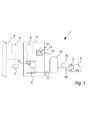
図1は、本発明の実施の形態に係るHRS1の模式図を例示している。HRS1は、供給ネットワーク4、外部水素ストレージ5、内部水素ストレージ6、又は一時的水素ストレージ7の形状の水素供給源から、車両3の受取り容器2へ水素を供給する。
FIG. 1 illustrates a schematic diagram of an
水素の圧力、温度、流量、時間などを、車両3に水素を燃料補給するための、例えば、SAE J2601規格のような現在の規格に準拠するように調整するために、HRS1は、コンプレッサ8と、冷却システム9と、制御及び監視システム10を備え、これらはすべて、好ましくは、HRS1の筐体11内に位置している。
In order to adjust the pressure, temperature, flow rate, time, etc. of the hydrogen so as to comply with current standards such as the SAE J2601 standard for refueling the vehicle 3 with hydrogen, the HRS 1
燃料補給プロセスは、幾つかの状態を含み、ユーザから燃料補給を要求されたときに「準備完了状態」から「燃料補給前状態」に移行することを含む。ユーザがノズルを持ち上げ、ノズルを車両に取り付けると、ユーザは、「燃料補給スタートアップ状態(Refueling Start Up State)」を開始でき、車両の容器の開始圧力が決定される。開始圧力が決定されると、他の初期パラメータ「主要燃料補給状態(Main Refueling State)」が行われ、水素が、車両の容器を充填する目的で車両の容器に提供される。燃料補給が完了すると、「燃料補給停止状態(Refueling Stop State)」になり、準備完了状態に戻るための、ホース及びノズル内の水素を空にするような準備が行われる。 The refueling process includes several states and includes transitioning from a “ready state” to a “pre-refueling state” when a user requests refueling. When the user lifts the nozzle and attaches the nozzle to the vehicle, the user can start a “Refueling Start Up State” and the starting pressure of the vehicle's container is determined. Once the starting pressure is determined, another initial parameter “Main Refueling State” is performed and hydrogen is provided to the vehicle container for the purpose of filling the vehicle container. When the refueling is completed, a “fuel replenishment stop state (Refueling Stop State)” is entered, and preparation for emptying the hydrogen in the hose and nozzle is performed to return to the ready state.
制御及び監視システム10は、下記により詳細に記述される、安全コントローラ12とプロセスコントローラ13を含む。
The control and
HRS1のほとんどの位置において、HRS筐体11を、ホース15とノズル16(水素取出し口)により車両3に接続可能なディスペンサ14から物理的に分離することは好適である。HRS筐体11とディスペンサ14は、水素を、HRS1から、ディスペンサ14を介して、車両3の受取り容器2に供給するための1つ以上の供給ライン17により接続される。
In most positions of the
図1に例示されているHRS1は、分離されて、供給ライン17で接続されている筐体11とディスペンサ14を備えているように例示されているが、水素供給源4、5、6、7から、ノズル16として図1に例示されている水素取出し口までのHRS1の構成要素、及び、その間の水素流路におけるすべて(弁、トランスデューサ、アクチュエータなど、すなわち、水素流量を制御するために使用されるすべての構成要素)は、完全に1つの筐体に統合でき、又は図1に例示されているように、1つ以上の個々の構成要素とすることができるということは言及されるべきである。
The
図2は、本発明の実施の形態に係るHRS1の制御及び監視システム10の模式図を例示している。
FIG. 2 illustrates a schematic diagram of the control and
制御及び監視システム10の主な目的は、HRS1が、安全性及び燃料補給の両者に関して、すべての関連規格に準拠することを確実にすることである。従って、制御及び監視システム10は、図2においては、水素ライン19(ラインは、水素の流量を容易にするパイプのことである)における圧力Pを測定している複数のトランスデューサ18a、18b(全体として18と称される)からの入力を受信している。しかし、トランスデューサ18は、水素供給源4、5、6、7から、ノズル16における水素取出し口までのHRS1におけるいずれの場所にも位置できる。更に、トランスデューサ18はまた、HRS筐体11の内部及び外部の温度などのような外部値に関する入力も提供できる。トランスデューサ18は、流量、圧力、温度、弁の位置などに関する入力を提供している。
The main purpose of the control and
トランスデューサ18aは、プロセス測定装置の例であり、トランスデューサ18bは、安全測定装置の例であるということは言及されるべきである。
It should be mentioned that
入力は、制御及び監視システム10により、圧力、温度、流量などを調整するために使用される。図2においては、この制御は、例示されている弁20a、20b(全体として20と称される)により容易にされ、弁20は、水素ライン21における流量を制御し、それにより、ディスペンサ14への供給ライン17とディスペンサ14における流量を制御する。制御及び監視システム10により行われる制御は、好ましくは、コンプレッサ8、冷却システム9、弁20などを制御することにより行われる。
The inputs are used by the control and
弁20aは、最終プロセス要素の例であり、弁20bは、最終安全要素の例であるということは言及されるべきである。
It should be mentioned that
安全コントローラ12とプロセスコントローラ13は通信できるが、下記に記述するように、安全に対する理由から、安全コントローラ12のみがプロセスコントローラ13に情報を提供することが好適である。このため、本発明の実施の形態においては、制限された情報を、プロセスコントローラ13から安全コントローラ12に送ることができ、この例としては、プロセスコントローラ13が活動中/オンラインであることを示すウォッチドッグ信号がある。安全コントローラ12の監視及び制御(すなわち、好ましくは、HRS1の作動のトリップ)で使用されるデータは、プロセスコントローラ13から提供されない。
Although the
トリップは、HRSの作動を、いずれかの通常プロセス状態から、安全状態にすることと理解されるべきで、それは、ほとんどの場合、例えば、水素流量を制御する弁を開閉することによりHRSの作動を停止又は閉鎖することを意味する。これは、HRSが作動する温度及び圧力の両者の制御が困難であり、適切に制御されない場合、人に対して危険であり得るという点において利点がある。 A trip should be understood as bringing the operation of the HRS from any normal process state to a safe state, which in most cases, for example, by opening and closing a valve that controls the hydrogen flow rate. Is stopped or closed. This is advantageous in that it is difficult to control both the temperature and pressure at which the HRS operates and can be dangerous to humans if not properly controlled.
コントローラ12と13との間(好ましくは、安全コントローラ12からプロセスコントローラ13へのみ)で交換された情報は、安全コントローラ12により扱われるすべてのデータを含むことができる。従って、HRS1の作動の状態又はモード、閾値、測定されたパラメータ/値などに関するデータは、プロセスコントローラ13により記録できる。そのようなデータがプロセスコントローラ13に提供された場合は、そのデータは、HRS1の制御において使用されないということは言及されるべきである。従って、そのようなデータは、プロセスコントローラ13により得られる測定値の検証に使用できる。
The information exchanged between the
しかし、安全コントローラは、基本プロセス制御機能の実行における、例えば、最後の漏洩チェックから所与の時間が経過した状況において、割り込みを容易にできる。典型的には、安全コントローラ12がHRSの作動をトリップした場合、これは、プロセスコントローラにより、その測定装置を介して観測され、続いて、プロセスコントローラもまた作動の安全モードに変化する。作動の通常モードはスタンバイ及び燃料補給モードを含み、作動の非通常モードは、作動の安全及び緊急モードを含むことができる。従って、燃料補給モードのようなHRSの作動の通常モードは、構成要素の故障がなく、制御ソフトウェアのエラーが起きず、すべてのパラメータがその閾値内に保たれているときに起こる。作動の安全モード又は緊急モードのような、HRS1の作動の非通常モードは、構成要素が故障し、制御ソフトウェアが故障し、パラメータがその閾値を超え、燃料補給に対する現在の規格に準拠しなくなり、又は、HRS1の近くの人間に対する危険などという結果になるときに起こる。
However, the safety controller can facilitate interrupts in the execution of basic process control functions, eg, in situations where a given time has elapsed since the last leak check. Typically, if the
図2においては、制御及び監視システム10の安全コントローラ12とプロセスコントローラ13と、トランスデューサ18と、及び最終要素20は、通信ライン22a、22b、22cを介して通信しているように例示されている。しかし、安全コントローラ12と、その安全測定装置18b及び最終安全要素20b、すなわち、まとめて安全計装システム又は、略してSISと称されるものとの間の分離した通信のような代替通信構成も好適である。安全計装システムの通信に加えて、又はそれと平行して、プロセスコントローラ13とそのプロセス測定装置18a及び最終プロセス要素20a(まとめて、基本プロセス制御システム、略してBPCSと称される)との間の分離した通信は好ましくは容易にされる。通信経路22a、22b、22cは、1つ以上の通信システムにおいて、有線である必要はないということは言及されるべきである。通信は、少なくとも部分的には、任意の種類の無線通信、及び可能であれば、任意の種類の通信バスなどとして実現できる。
In FIG. 2,
従って、制御及び監視システム10は、プロセスコントローラ13によりHRS1の制御を容易にし、この制御の監視を安全コントローラ12により容易にする。
Therefore, the control and
本発明の実施の形態によれば、安全コントローラ12によるHRS1の監視は、好ましくは、動的閾値に基づく。これは、測定されるパラメータの値が、HRS1の作動のモードによっては異なる限界を有することを可能にする。従って、スタンバイモードにおいては、ディスペンサ14における水素の圧力及び温度は、圧力及び温度の値が現在の規格に準拠すべき燃料補給モードにおける値よりも小さいことが可能とされる。
According to an embodiment of the invention, the monitoring of
従って、安全コントローラ12は、パラメータに対する1つ以上の閾値をリアルタイムで決定して、これらの決定された閾値の安全性を、安全測定装置18bにより測定されるパラメータにより評価する。閾値は、テーブルルックアップから決定されてよく、所与の状況/モードに対して予め決定されてよく、値は、例えば、作動のモードに基づいて決定される。すなわち、閾値は、スタンバイモードにおいては第1の値を、燃料補給モードにおいては第2の値を有することを可能とされ、第1の及び第2の値の両者は、テーブルから見出すことができる。
Accordingly, the
測定されたパラメータと決定された閾値の評価(安全又はプロセス評価)は、測定されたパラメータの規格化、複数の測定されたパラメータの比較、計算などの数学的操作を含むことができる。この例としては、流量計算が、2つの圧力測定値及び温度測定値に基づいて行われることが挙げられる。圧力は、圧力降下を提供する構成要素の両側において測定される。水素の温度を知ることで、水素の密度を計算でき、水素の流量を決定するときに使用される。例えば、作動モードの変更を示すために使用される測定値を測定する測定装置18bからの入力を安全コントローラ12が得るという点において、評価が可能とされ、動的とされる。そのため、例えば、ディスペンサ14に位置している弁の1つを監視している弁ポジショナから受信したパラメータが、弁状態「閉(CLOSE)」を示すパラメータから「開(OPEN)」を示すパラメータに変化したときに、安全コントローラ12は、この入力を使用して、現在作動モードは、例えば、スタンバイから燃料補給モードに変化したと判定する。
Evaluation of measured parameters and determined thresholds (safety or process evaluation) can include mathematical operations such as normalization of measured parameters, comparison of multiple measured parameters, calculations, and the like. An example of this is that the flow calculation is based on two pressure measurements and a temperature measurement. The pressure is measured on both sides of the component that provides the pressure drop. Knowing the temperature of hydrogen, the density of hydrogen can be calculated and used when determining the flow rate of hydrogen. For example, the evaluation is possible and dynamic in that the
本発明の実施の形態によれば、ユーザは、燃料補給を、ユーザインタフェースUIを介して、例えば、安全コントローラ12とプロセスコントローラ13の両者により記録される支払により燃料補給を開始する。そして、安全コントローラ12は、例えば、弁ポジショナ18bからの情報を使用して、スタータ圧力をいつ得るかを決定する。同じように、弁ポジショナと圧力センサ18bからの情報は、水素ストレージにおけるシフト(燃料補給に使用される)がいつか、及びいつ燃料補給が終わるかを決定するために使用できる。
According to an embodiment of the present invention, a user initiates refueling via a user interface UI, for example, with payment recorded by both the
安全コントローラ12が監視するとき、及び少なくともHRS1を部分的に制御するときに基づく閾値はまた「固定」であってよく、例えば、圧力及び温度のような入力値に基づいてルックアップテーブルから見出すことができるということに留意すべきである。閾値が「固定」又は動的かは、続く燃料補給プロトコルにより決定できる。好適な燃料補給プロトコルは、SAE J2601規格において見出される。固定閾値の例としては、規格又はノズルの定格圧力のいずれかにより決定される、ノズルにおける圧力を挙げることができる。最大可能ノズル圧力に対する閾値は、例えば、830バールである。
The threshold based on when the
或いは、安全コントローラ12及び関連する安全計装機能により、作動のウィンドウ(Window of Operation)内で監視される作動パラメータに対する限界又は閾値は、動的であってよい。これは、燃料補給の第1の部の間は、例えば可能な温度に対する閾値は、燃料補給の第2の部の間の温度とは異なっているからである。従って、個々の安全計装機能がこれを考慮し、その入力を現在の閾値に対して評価すると、有利である。従って、1つの温度は、HRSの作動の制御(好ましくは、トリップのみ)において、燃料補給プロセスの1つの部分において安全コントローラからの相互作用を開始し、別の部分では開始しない。
Alternatively, the limits or thresholds for operating parameters that are monitored within the window of operation by the
プロセスコントローラ13は、スタンバイモードは燃料補給モードに変化すべきであるという入力を、その測定装置18aから、例えば、ユーザがノズルをディスペンサ14から取り外した、ディスペンサ14におけるユーザインタフェースUIが起動された、支払が受諾されたなどが登録されたときに受信する。上記のように、安全コントローラ12は好ましくは、同じ入力をそれ自身の安全測定装置18bから受信する。
The
そして、安全コントローラ12は、その制御ソフトウェアに基づいて、閾値を決定できる。パラメータによっては、閾値は、パラメータに対する上方値と下方値の両者を含むこと、すなわち、パラメータ値がその内部でなければならない細い区間を含むことができる。トランスデューサ18による測定されるパラメータ値は、典型的には、圧力、温度、流量などを直接又は間接的に表す。
And the
測定されたパラメータが、パラメータが細い区間から外れようとしている、又は外れた、又は閾値を越えたことを示す場合は、安全コントローラ12は、作動のモードを、通常から非通常の作動のモードに変更できる。安全コントローラ12は、作動のモードを、弁のような、その最終要素20bの1つを制御して、例えば、車両3への水素の流量を停止することにより変更できる。これは、好ましくは、車両3の燃料補給を制御するプロセスコントローラ13との相互作用及び情報の交換がまったくなく行われる。
If the measured parameter indicates that the parameter is about to fall out of a narrow section, or has gone out of threshold or exceeded a threshold, the
そのような状況において、安全コントローラ12は、好ましくは、プロセスコントローラ13に作動モードの変更を通知する。これは、プロセスコントローラ13もまた、新しい作動モードに従って制御でき、例えば、その制御可能最終要素20aの1つを閉じることができるという点において利点がある。
In such a situation, the
図3を参照して、上記の例を記述する。プロセスコントローラ13は、ユーザが車両3の燃料補給を開始しているという入力を、ユーザインタフェースUIから受信する。そして、プロセスコントローラ13は、作動のモードをスタンバイモードから、ディスペンサ14から車両3への水素の流量を容易にする弁V1を開くことを含む、作動の燃料補給モードに変更する。燃料補給の間、水素ライン21の領域Aにおける圧力P1は、プロセスコントローラ13により、圧力トランスデューサP1pで測定される。ユーザインタフェースUIと圧力トランスデューサP1pは両者とも、プロセス測定装置18aの例であり、弁V1は、最終プロセス要素20aの例であるということは言及されるべきである。
The above example will be described with reference to FIG. The
安全コントローラ12は、弁V1が開けられたという入力を、弁ポジショナVP1から受信し、この情報を使用して、例えば、領域Aでの水素ライン21における水素の許容圧力P1に対する閾値を決定することを開始する。弁ポジショナVP1と圧力トランスデューサP1は、安全測定装置18bの例であるということに留意すべきである。
The
作動の燃料補給モードは、現在の燃料補給規格に準拠するために、プロセスコントローラ13により制御及び監視される。燃料補給の間、水素ライン21の領域Aにおける圧力は、安全コントローラ12による圧力トランスデューサP1sと、プロセスコントローラ13による圧力トランスデューサP1pの両者により測定される。
The refueling mode of operation is controlled and monitored by the
好ましくは、圧力を測定するトランスデューサP1sとP1pとの間の距離は0から2メートルの間であり、好ましくは、1メートル未満である。図3において、トランスデューサP1pとP1sは直列に例示されているが、並列に位置させることもできる。 Preferably, the distance between transducers P1s and P1p for measuring pressure is between 0 and 2 meters, preferably less than 1 meter. In FIG. 3, the transducers P1p and P1s are illustrated in series, but may be positioned in parallel.
通常は、例えば、領域Aにおける圧力がその閾値を超えた場合は、プロセスコントローラ13は、例えば、水素の流量を停止する1つ以上の最終プロセス要素を閉じることにより、燃料補給モードを確実に中断させる。しかし、1つ以上のプロセス測定装置18aからの入力がなかったり、又はその入力が誤った判断を示したり、制御ソフトウェアがクラッシュしたり、1つ以上の最終プロセス要素20aが誤作動したときは、水素の流量をタイムリーに停止させることはできない。
Typically, for example, if the pressure in region A exceeds its threshold, the
そのような状況においては、安全コントローラ12は、作動の通常モードから、非通常モードへの変化を確実にする。これは、好ましくは、安全制御ソフトウェアである制御ソフトウェアを含む安全コントローラ12と、測定装置18bと、最終安全要素20bを備える安全計装システムにより可能であり、好ましくは、これらはすべて、プロセスコントローラ13と、その制御ソフトウェアと、測定装置18aと、最終プロセス要素20aとは完全に独立している。
In such a situation, the
手短に述べれば、プロセスコントローラ13は、現在の規格の従ってHRS1を制御するということができるが、一方、安全コントローラ12は、HRS1の作動を監視し、現在の規格が遵守されない場合に行動を起こすだけである。追加的に、当然好ましいことであるが、安全コントローラ12はまた、例えば、水素ストレージ、パイプなどの設計限界を超えているかも監視する。そのような監視は、圧力、温度などと関連することができる。
In short, the
従って、領域Aにおいて測定された圧力のような第1のパラメータがその閾値(すなわち、許容値/制限値、好ましくは現在の規格により定義される)を超えた場合、安全コントローラ12は、なぜこれが起きているかを知ることはできず、また、なぜプロセスコントローラ13が行動を起こさないかを知ることはできないが、安全コントローラ12は、例えば、水素の流量を確実に停止し、それにより、プロセスコントローラ13の制御を支配する。
Thus, if the first parameter, such as the pressure measured in region A, exceeds its threshold (ie, the tolerance / limit value, preferably defined by the current standard), the
プロセスコントローラ13により使用される閾値は、典型的には、安全コントローラ12における閾値よりも控えめである。これは、例えば、必要なときにHRS1を閉鎖するのはプロセスコントローラであることが好適であるからである。このため、2つのコントローラ12、13において同じ閾値により作動することにより、最大の安全を維持しながら、より大きな作動ウィンドウが得られる。
The threshold used by
図3を参照すると、これは、トランスデューサP1s、18bにより例示されており、これらが、決定された閾値を超える圧力を測定したときは、この情報は、安全コントローラ12により使用されて、弁V2を閉じ、通信経路22aを介して、その制御行動又は作動モードの変更がプロセスコントローラ13に通信される。弁V2は、最終安全要素20bの例であるということは言及されるべきである。
Referring to FIG. 3, this is illustrated by transducers P1s, 18b, and when they measure a pressure that exceeds a determined threshold, this information is used by the
例えば、欠陥のあるプロセス測定装置及びデータプロセッサ、ソフトウェアエラーなどの場合、プロセスコントローラ13は、閾値を超えたことを観測できす、V1を閉じることを開始しないため、緊急状況のリスクが起こる。そのような状況を防止するため、本発明は、並列安全計装システムを使用する。従って、安全コントローラ12からの通信に基づいて、プロセスコントローラ13は、好ましくは、弁V1を閉じ、それにより、燃料補給プロセスは、好ましくは、安全コントローラ12が弁V2を閉じ、プロセスコントローラ13が弁V1を閉じるという両方のことにより中断される。
For example, in the case of a defective process measurement device and data processor, software error, etc., the
安全コントローラ12が、HRS1の作動を中断すると、これは、典型的には、基本プロセス制御システムにおけるある種の誤作動を示す。従って、この事象の根本原因を調べることがしばしば必要となる。そのような調査は、コントローラ12、13からのデータを解析すること、及びエラーの手動又は自動リセットの前の、測定装置18と最終要素20の手動による調査を含むことができる。
When the
典型的には、いわゆるハード閾値を超えると、安全コントローラにより行われたトリップは、手動によるリセットを必要とする。これは、そのようなエラーはあってはならないことであるべきであるが、それが起こったので、サービス要員は、そのようなエラーの原因を調べなければならない。ハード閾値の例としては、例えば、830バールのノズルの最大圧力を挙げることができる。 Typically, above the so-called hard threshold, trips made by the safety controller require a manual reset. This should be such an error should not be, but as it has occurred, service personnel should investigate the cause of such an error. As an example of a hard threshold value, for example, the maximum pressure of a nozzle of 830 bar can be mentioned.
例えば、水素温度が少し高過ぎるというような、燃料補給に関連するエラーは、プロセスコントローラ13により補正されるべきである。しかし、何らかの理由で、温度を下げられないときは、安全コントローラは、燃料補給プロセスをトリップ又は中止できる。しかし、そのようなエラーは、後続する燃料補給プロセスを妨げるべき種類のものではないので、自動的にリセットできる。
For example, errors related to refueling, such as the hydrogen temperature being a little too high, should be corrected by the
測定装置/トランスデューサは、好ましくは、ディスペンサ14における質量流量、ディスペンサ14からの水素流量を制御する弁の位置、ノズルに可能な限り近い位置での圧力、ディスペンサ14からの水素流量の温度などを測定する。更に、車両からの、例えば、赤外線通信チャネルを介しての情報は、安全コントローラ12へのデータと、プロセスコントローラ13へデータに分割でき、又は、例えば、安全コントローラ12を介してプロセスコントローラ13へのようにして、両者のコントローラ12、13へのデータに分割できるということは言及されるべきである。
The measuring device / transducer preferably measures the mass flow rate at the
上記の記述から、本発明の制御システム10は、HRS1の作動を制御するプロセスコントローラ13を容易にし、すなわち、制御ソフトウェアにおけるいずれのステップが次に行われるべきか、ということについて容易にするということが今では明白である。これは、HRS1の監視事象に基づいて、例えば、プロセスコントローラ13が、HRS1の制御の次のステップに移行するかどうかを評価する安全コントローラ12とは反対である。
From the above description, the
明白なことであるが、安全コントローラ12に対する要請は、プロセスコントローラ13に対する要請とはまったく異なる。例として、安全コントローラ12は、HRSの監視に基づいて、例えば、燃料補給プロセスを停止するか又は一時中断するかの差を推定しなければならない。この例としては、安全コントローラは、いわゆるバンクシフトによる弁の閉鎖と、燃料補給の終了(すなわち、燃料補給のプロセスにおける一時中断であり、停止ではない)とを区別できる能力を有するべきであるということが挙げられる。
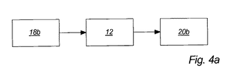
図4aは、安全計装システム、すなわち、最終安全要素20bを制御する安全コントローラ12に入力を提供する安全測定装置18bの模式図である。従って、図4aは、安全コントローラ12により制御される安全計装システムに関連するのみであるが、プロセスコントローラ13により制御される基本プロセス制御システムの類似の模式図も存在する。測定装置18bと最終要素20bが好ましくは接続されるI/Oモジュールは例示されていない。これらのI/Oモジュールは、好ましくは、ケーブルを介して、安全コントローラ12のI/Oモジュールに接続される。
Obviously, the request for the
FIG. 4a is a schematic diagram of a safety instrumented system, i.e., a
安全計装システム(Safety Instrumented System(SIS))に言及するときは、重要プロセスシステムにおいて特に使用される、ハードウェア及びソフトウェア制御の設計されたセットを備えるシステムに言及しているということは、言及されるべきである。重要プロセスシステムは、いったん稼働し、作動上の問題が起こると、逆の「安全、健全、及び環境(Safety、Health and Environment」という結果を回避するために、「安全状態(Safety State)」にすることが必要なシステム、すなわち、危険状況における、又は危険状況を回避するためにHRS1の作動をトリップすることが必要となるようなシステムとして識別できる。
When referring to a Safety Instrumented System (SIS), it is mentioned that it refers to a system with a designed set of hardware and software controls used specifically in critical process systems. It should be. Once the critical process system is running and operational problems occur, the “safety state” is entered to avoid the opposite “safety, health and environment” results. It can be identified as a system that needs to be done, i.e. a system that needs to trip the operation of the
SISにより行われる特定制御機能は、安全計装機能(Safety Instrumented Function(SIF))と称される。SIFは、些細な機器の損傷から、エネルギー及び/又は物質の、制御不能な破局的放出を含む事象にわたる、以前に識別された安全、健全、及び環境事象の可能性を削除するために意図されている、総合リスク削減対策の一部として実現される。 The specific control function performed by the SIS is referred to as a safety instrumented function (SIF). SIF is intended to eliminate the possibility of previously identified safety, health and environmental events ranging from minor equipment damage to events involving uncontrolled catastrophic releases of energy and / or materials. It is realized as part of comprehensive risk reduction measures.
安全コントローラは、信号処理及び、固有SIFにより識別される別個の機能を実行するためのロジックを含む。従って、SIFは、測定装置18bから入力を受信し、最終要素20bを制御する安全コントローラの一部として実現される。
そのため、安全計装システム(SIS)は、容認できないプロセス条件が検出されたときに、プロセスの安全状態を維持するように設計されている。SISに関連する計装機器(Instrumentation)及び制御機器は、基本プロセス制御システムとは独立して作動する。
The safety controller includes signal processing and logic for performing separate functions identified by the unique SIF. Thus, the SIF is implemented as part of a safety controller that receives input from the measuring
As such, safety instrumented systems (SIS) are designed to maintain a safe state of the process when unacceptable process conditions are detected. Instrumentation and control equipment related to the SIS operates independently of the basic process control system.
基本プロセス制御は、例えば、範囲外である圧力又は温度を、再び範囲内にするための制御行動を適切に行う保護の第1のレイヤを提供する。安全コントローラのSIFは、保護の第2のレイヤであり、基本制御が、例えば、温度又は圧力を範囲内に戻せないときに使用され、従って、SIFは、危険な状況を防止する。SIFを必要とする構成要素又は制御機能は、リスク解析により決定される。最終的に、安全コントローラが、何らかの理由で、危険な状況を、例えば、作動をトリップすることにより停止しない場合は、第3のレベル、すなわち、機械的圧力制御弁を起動できる。 Basic process control, for example, provides a first layer of protection that properly takes control action to bring a pressure or temperature that is out of range back into range. The safety controller's SIF is the second layer of protection, and basic control is used, for example, when the temperature or pressure cannot be brought back into range, and therefore the SIF prevents dangerous situations. The components or control functions that require SIF are determined by risk analysis. Finally, if for some reason the safety controller does not stop a dangerous situation, for example, by tripping operation, a third level, i.e. a mechanical pressure control valve, can be activated.
SISはまた、燃料補給プロセスのどこに、であるか、すなわち、プロセスコントローラの何れの状態であるかを、弁の位置、圧力、質量流量などにおける変化のパターンを観測することにより識別できる。プロセスコントローラが、燃料補給プロセスのどこであるかを知ることにより、SIS、従ってSIFは、作動のそれぞれのウィンドウがいつ開閉するかを知る。例としては、燃料補給に対する圧力傾斜を監視することを挙げることができ、そのウィンドウは、車両の開始圧力が測定されたときに開き、例えば、放出弁が開いたときに閉じることができる。 The SIS can also identify where in the refueling process, ie, what state of the process controller, by observing a pattern of changes in valve position, pressure, mass flow, etc. By knowing where the process controller is in the refueling process, the SIS, and thus the SIF, knows when each window of operation opens and closes. An example may be monitoring the pressure ramp for refueling, the window opening when the vehicle starting pressure is measured, for example closing when the discharge valve is opened.
図4bは、HRS筐体11、及び図4aに例示されている安全計装システムの構成要素のHRS1のディスペンサ14における位置を例示している。安全計装機能(SIF)の幾つかの例を、ここで図4bを参照して記述する。
FIG. 4b illustrates the position of the
上述したように、安全計装システムは、1つ以上の安全計装機能を備え、それぞれの安全計装機能は、HRS1の1つ以上の安全関連故障モードを監視する。更に、安全計装機能は、安全計装システムの最終要素が、安全計装機能により検出された危険要素が進展することを停止、又はその危険要素を削除するために起動されることを確実にする。 As described above, the safety instrumented system comprises one or more safety instrumented functions, each safety instrumented function monitoring one or more safety-related failure modes of HRS1. In addition, the safety instrumented function ensures that the final element of the safety instrumented system is activated to stop or delete the risk factor detected by the safety instrumented function. To do.
SIF(安全計装機能)の第1の例は、車両開始圧力監視に関する。
このSIFは、燃料補給の特別なフェイズ、すなわち、受取り容器2の圧力と、ディスペンサ14、例えば、水素ライン21における水素の圧力と、の間の圧力均等化ステップの間の安全として意図されている。
このSIFは、ユーザが燃料補給を開始した後10秒開く作動のウィンドウにおいて、HRSの作動をトリップできるのみであるべきである。これは、弁ポジショナで、安全コントローラ12により検出できる。従って、圧力均等化の作動のウィンドウは、例えば、質量流量が検出され、基準が満たされたときに開始でき、安全コントローラ12が、ディスペンサノード弁(Dispenser Node Valve)及びディスペンサノズル弁(Dispenser Nozzle Valve)が共に閉じた位置であることを検出したときに終了される。
A first example of SIF (safety instrumentation function) relates to vehicle start pressure monitoring.
This SIF is intended as a safety during a special phase of refueling, ie the pressure equalization step between the pressure of the receiving vessel 2 and the pressure of hydrogen in the
This SIF should only be able to trip the operation of the HRS in a window of operation that opens 10 seconds after the user starts refueling. This can be detected by the
このSIFは、圧力トランスデューサP2(安全測定装置18b)からの入力を必要とし、この入力に基づいて、安全コントローラ12は弁V3(最終安全要素20b)を制御する。
そのような制御は、例えば、60秒以内に圧力が均等化されない場合に、水素の流量を停止することを含むことができる。
This SIF requires an input from the pressure transducer P2 (
Such control can include, for example, stopping the hydrogen flow if pressure is not equalized within 60 seconds.
SIFの第2の例は、燃料補給スタートアップの際の漏洩チェックに関する。ディスペンサ14のホース15は、HRS1と車両3との間の直接インタフェースである。安全且つ信頼性のある燃料補給を確実にするために、ホース15は、燃料補給スタートアップシーケンスにおいてチェックされ、所与の時間枠の間に、有意の圧力を失ってはならない。
このSIFは、燃料補給の特別なフェイズ、すなわち、ホース燃料補給漏洩チェックの間の安全として意図されている。
このSIFは、プロセスコントローラ13と安全コントローラ12が、水素ライン21における流量を検出したときに開く作動のウィンドウにおいて、HRS1の作動をトリップできるのみであるべきである。ウィンドウは、漏洩チェックが完了したときに閉じる。
このSIFのロジックは、弁V4の位置を監視する弁ポジショナV4posと、圧力トランスデューサP2と、温度トランスデューサT1を含む安全測定装置18bからの入力を必要とする。これらの入力に基づいて、安全コントローラ12は、弁V3を含む最終安全要素20bを制御する。
そのような制御は、例えば、1バール及び50℃の違いが第1の圧力/温度チェックと、例えば2秒の時間間隔をおいた、第2の圧力/温度チェックとの間にあるときに、弁V3を閉じることを含むことができる。
A second example of SIF relates to leak checking during refueling startups. The
This SIF is intended as a safety during a special phase of refueling, ie hose refueling leak check.
This SIF should only be able to trip the operation of the
This SIF logic requires input from a
Such control is, for example, when the difference between 1 bar and 50 ° C. is between a first pressure / temperature check and a second pressure / temperature check with a time interval of eg 2 seconds, Closing valve V3 may be included.
SIFの第3の例は、ディスペンサにおける、過剰水素流量監視に関する。ディスペンサ14における水素流量は、既知の流量規制全体にわたる圧力差に基づいて計算される。質量流量は、2つの圧力トランスミッタを含み、中間制御弁が閉じられた場合は、水素の流量を不可とし、誤った流量計算という結果になる。これを回避するために、上記の制御弁の状態が、弁ポジショナ(Valve Positioner)により、安全コントローラ12に供給される。測定された(計算された)質量流量が、容認可能な限界を、弁が開いている間に、例えば、2秒より長く超える場合は、燃料補給は、弁のような最終安全要素20bを閉じることによる停止される。この安全統合システムに対する作動のウィンドウは、HRS1の通常作動の間は、常に開いている。
A third example of SIF relates to excess hydrogen flow monitoring in a dispenser. The hydrogen flow rate in the
このSIFのロジックは、ディスペンサ14における水素の質量流量の入力と、ノズル弁の状態を監視する弁ポジショナからの信号を必要とする。従って、ディスペンサ14における計算された質量流量が、例えば、0.060kg/秒の限界を、制御弁ポジショナがノズル弁は開いていることを示している間に、2秒より長く超えた場合は、コンプレッサの作動はトリップし、最終安全要素20bは閉じ、HRS1における異なる位置での水素流量を停止する。更に、プロセスコントローラ13は通知される。このSIFからのトリップは、手動によるリセットを必要とする。
This SIF logic requires the input of a hydrogen mass flow rate in the
SIFの第4の例は、水素供給圧力監視である。主要燃料補給期間の間、HRSは、燃料補給ルックアップテーブルに基づいて、平均圧力傾斜率(Average Pressure Ramp Rate)値を目標に圧力を加える。加えられる圧力は、主要燃料補給期間経過時間に基づく、上方及び下方許容誤差内であるべきである。主要燃料補給期間の最初の5秒間を除いて、圧力傾斜を、上方及び下方許容誤差内に維持することができない場合は、HRSは、5秒以内に燃料補給を停止すべきである。
このSIFは、燃料補給の特別なフェイズ(主要燃料補給状態)の間の安全として意図され、安全コントローラ12が必要な燃料補給パラメータを判定したときに開き、燃料補給完了状態になったとき、すなわち、弁ポジショナが、ホース及びノズルの水素の放出を容易にする放出弁が開いていると測定したときに閉じる作動のウィンドウにおいて、トリップができるのみであるべきである。
このSIFのロジックは、ノズル圧力トランスミッタからの入力を必要とし、この圧力が上方及び下方閾値の間であることを監視する。上方閾値を超えると、安全コントローラは、HRS1の作動をトリップする。圧力が、下方閾値を下回ると、ポーズタイマーが作動していない限り、HRS1の作動はトリップされる。主要燃料補給状態の最初の5秒間を除いて、ノズル圧力が1/2×平均圧力傾斜率より小さい圧力増加を体験すると、ポーズタイマーが指定され、すなわち、ノズル圧力の測定及び格納が一時中断される。ポーズタイマーがオンの間、上方及び下方圧力許容誤差(Upper and Lower Pressure Tolerance)は一定に保たれ、圧力は、HRS1の作動のトリップを容易にすることなく、閾値以下に低下できる。
ポーズタイマーは、ディスペンサ供給圧力トランスミッタが、1/2×平均圧力傾斜率を超える圧力増加を体験すると停止され、上方及び下方圧力許容誤差の展開がここで再開される。例えば、20から35秒後に、ポーズタイマーがタイムアウトとなる場合、HRS1の作動がトリップされると好適である。更に、ノズル圧力から、一時中断中(例えば、水素供給の変更を容易にするための間)の間に測定された圧力を差し引いた圧力の絶対値が、100バールよりも小さく、ノズル圧力が、下方閾値未満である場合で、ポーズタイマーが停止されてから、例えば、最大10秒が経過するときも、HRS1の作動はトリップされる。これにより、例えば、バンクシフトの間に最初に気付かれる、燃料補給中の漏洩の徴候が得られる。
A fourth example of SIF is hydrogen supply pressure monitoring. During the main refueling period, the HRS applies pressure to the average pressure ramp rate value based on the refueling lookup table. The applied pressure should be within upper and lower tolerances based on the elapsed time of the main refueling period. If the pressure ramp cannot be maintained within the upper and lower tolerances except for the first 5 seconds of the main refueling period, the HRS should stop refueling within 5 seconds.
This SIF is intended as safety during a special phase of refueling (primary refueling state) and opens when the
The SIF logic requires input from the nozzle pressure transmitter and monitors that this pressure is between the upper and lower thresholds. If the upper threshold is exceeded, the safety controller trips the operation of HRS1. When the pressure falls below the lower threshold, the activation of HRS1 is tripped unless the pause timer is activated. Except for the first 5 seconds of the main refueling condition, when the nozzle pressure experiences a pressure increase that is less than 1/2 x the average pressure ramp rate, a pause timer is specified, i.e. the measurement and storage of the nozzle pressure is suspended. The While the pause timer is on, the upper and lower pressure tolerances are kept constant, and the pressure can drop below the threshold without facilitating tripping of HRS1 operation.
The pause timer is stopped when the dispenser supply pressure transmitter experiences a pressure increase that exceeds the ½ × average pressure ramp rate, and the development of the upper and lower pressure tolerances is now resumed. For example, if the pause timer times out after 20 to 35 seconds, it is preferable that the operation of the
SIFの第5の例は、ディスペンサ14における冷却区分の監視に関する。いずれの冷却区分、すなわち、30秒のスタートアップ期間の後、及び、意図的非燃料補給時間(Intended Non−Fueling Time)(例えば、バンクシフト(水素源の変更)、中間漏洩チェックなどにおいて起こる)後10秒後の、燃料補給の速度に対して決定する水素の温度間隔に対して、冷却区分は、その対応する温度範囲を維持すべきである。そのような温度範囲の例としては、マイナス33℃からマイナス40℃のT40冷却区分に対する温度範囲を挙げることができ、ここにおいて、水素温度が20秒以内に範囲に戻る場合は、マイナス30℃の水素温度も容認される。HRS1が燃料供給温度を、これらの冷却区分温度範囲に保持できない場合は、HRSの性能を削減する後退手順に従うか、可能な限り迅速に、しかし5秒以内に燃料供給を停止すべきである。上記の温度範囲は冷却区分(Cooling Catergory)として定義され、この安全計装機能が、アクティブに水素温度を監視する30秒前に決定される。従って、この安全計装機能の意図は、冷却区分の変化を倍にする、分配された水素の温度の変化は、シャットダウンという結果としなくてはならないということである。
この安全計装機能は、燃料補給の特別なフェイズ(主要燃料補給状態)の間の安全として意図され、作動のウィンドウにおいてトリップができるのみであるべきであり、作動のウィンドウは、燃料補給パラメータの状態(Refueling Parameter State)(平均圧力傾斜率と目標圧力のような燃料補給を開始するために必要なパラメータが判定される状態)の後、30秒開き、燃料補給完了又は停止状態(Complete or stop Refueling State)(燃料補給が終了した状態)に入ると、閉じる。
この安全計装機能は、ノズル温度測定装置から入力を得るので、ノズル温度が、現在の冷却区分に対する上限を超えた場合、「より熱い」冷却区分への変更が開始され、この変更について信号がプロセスコントローラ13に提供される。ノズル温度が、上限を2回超えると、安全コントローラ12がHRS1の作動をトリップすることが行われ、プロセスコントローラ13は通知される。
A fifth example of SIF relates to monitoring of the cooling section in the
This safety instrumented function is intended as a safety during a special phase of refueling (primary refueling condition) and should only be able to trip in the window of operation, After a state (Refering Parameter State) (a state in which parameters necessary to start refueling such as an average pressure gradient and a target pressure are determined), it opens for 30 seconds, and a refueling completion or stop state (Complete or stop) When entering (Refering State) (the state in which refueling is completed), it is closed.
This safety instrumentation function takes input from the nozzle temperature measurement device, so if the nozzle temperature exceeds the upper limit for the current cooling category, a change to the “hotter” cooling category is initiated and a signal is sent for this change. Provided to the
SIFの第6の例は、ディスペンサ14における、水素中間圧力監視に関する。主要燃料補給期間の間、HRS1は、燃料補給ルックアップテーブルに基づく、平均圧力傾斜率値を目標として圧力を加える。加えられる圧力は、主要燃料補給期間経過時間に基づく、上方及び下方閾値(平均圧力傾斜率の上方及び下方限界を定義する)内になるべきである。主要燃料補給期間の最初の5秒を除いて、HRS1は、圧力傾斜を上方及び下方閾値内に維持できない場合は、5秒以内に燃料供給を停止すべきである。
このSIFは、平均圧力傾斜率の閾値に関連する圧力を監視し、一時中断及び冷却区分の変更、及びバンクスイッチは、閾値の通常の時間依存展開を変更する可能性があるので、SIFは、平均圧力傾斜率の閾値を継続的に更新しなければならない。
このSIFの意図は、車両の燃料補給の間の圧力が、平均圧力傾斜率を定義する指定閾値を外れた場合は、これは、HRSの作動のトリップ、又は、ある期間の後に自動的にリセットされる燃料補給プロセスの少なくとも停止という結果にしなければならないということである。
このSIFは、燃料補給の特別なフェイズ(主要燃料補給状態)の間の安全として意図され、安全コントローラ12が、平均圧力傾斜率又は目標圧力のような必要な燃料補給パラメータを判定したときに開き、燃料補給完了状態(Complete Refueling State)になったとき、すなわち、例えば、ホース及びノズルから水素を放出する放出弁がプロセスコントローラ13により開けられたときに閉じる作動のウィンドウにおいてトリップができるのみであるべきである。
このSIFのロジックは、好ましくは、SIFの第4の例において上述したノズル圧力センサとは異なるノズル圧力センサからの入力を必要とする。このSIFのロジックは、同じ出力を有する、上述した第4の例のロジックのロジックとして作動する。
The sixth example of SIF relates to hydrogen intermediate pressure monitoring at the
This SIF monitors the pressure associated with the threshold of the average pressure ramp rate, and the SIF can change the normal time-dependent evolution of the threshold, as suspensions and cooling section changes, and bank switches can change the threshold. The average pressure ramp rate threshold must be continuously updated.
The intent of this SIF is that if the pressure during refueling of the vehicle deviates from a specified threshold that defines the average pressure ramp rate, this will automatically reset after an HRS trip or after a period of time. This should result in at least an outage of the refueling process being performed.
This SIF is intended as safety during a special phase of refueling (primary refueling condition) and opens when the
This SIF logic preferably requires input from a nozzle pressure sensor that is different from the nozzle pressure sensor described above in the fourth example of the SIF. This SIF logic operates as the logic of the fourth example logic described above having the same output.
SIFの第7の例は、目標圧力監視に関する。目標圧力は、安全燃料補給に対する上限を定義する。プロセスコントローラ13は、目標圧力(Target Pressure)から許容誤差を差し引いた圧力を、首尾よく終了する燃料補給を認識するために使用し、一方、安全コントローラ12は、このSIFを通してシャットダウンを行わなければならない。目標圧力は、燃料補給パラメータの状態において決定されるが、通信が途絶えた場合は、変更できる。通信の途絶えに対処するために、ステーションは、目標圧力を、通信あり燃料補給(refueling with Communication)から、通信なし目標圧力(Target Pressure without Communication)に変更できる。通信が途絶えたときに、ノズル圧力が非通信目標圧力(Non−communication Target pressure)を超えた場合は、燃料補給は停止される。
このSIFの意図は、プロセスコントローラ13が燃料補給の目標圧力から許容誤差を差し引いた圧力への到達に対する行動に失敗した場合に、HRS1の作動のトリップを強制するということである。目標圧力から許容誤差を差し引いたものは、燃料補給の成功する終了を決定する1つの手段である。
A seventh example of SIF relates to target pressure monitoring. The target pressure defines an upper limit for safe refueling. The
The intent of this SIF is to force a trip of operation of the
このSIFは、燃料補給の特別なフェイズ(圧力均等化状態(Pressure Equalization State))の間における安全として意図され、パラメータが開始されたときに開き、燃料補給完了状態が達成されたときに閉じる作動ウィンドウにおいて、トリップができるのみであるべきである。
このSIFのロジックは圧力トランスミッタ(例えば、ディスペンサ圧力供給トランスミッタと目標圧力)である。安全コントローラ12は、目標圧力のルックアップテーブル値を読まなければならず、安全コントローラは、目標圧力のルックアップテーブル値を、例えば、事前冷却温度区分の変更により、燃料補給充填シーケンスの間に変更できるということを知っていなければならない。従って、SIFは、ルックアップテーブル値をその作動のウィンドウ内で実行し、従って、SIFは、ルックアップ値を、圧力測定値と比較するだけである。
ディスペンサ圧力供給トランスミッタが目標圧力を超えた場合は、HRS1の作動はトリップされる。しかし、安全コントローラ12が、通信が途絶え、ディスペンサ圧力供給トランスミッタが、通信が途絶えたときの、車両との通信なしの燃料補給において容認される目標圧力よりも高いことを記録すると、10秒間待つ。この10秒の間に、圧力が50バールを超えて降下した場合は、プロセスコントローラ13は、燃料補給完了状態に入ったと仮定され、このSIFはもはやアクティブではなくなる。
このSIFによるHRS1のトリップは、コンプレッサの作動をトリップすることを含み、幾つかの安全最終要素20bは、閉じられて、HRS1における異なる位置での水素流量を停止する。更に、プロセスコントローラ13は通知される。このSIFからのトリップは、手動によるリセットが必要である。
This SIF is intended as a safety during a special phase of refueling (Pressure Equalization State) and opens when the parameters are started and closes when the refueling completion state is achieved You should only be able to trip in the window.
The logic of this SIF is a pressure transmitter (eg, dispenser pressure supply transmitter and target pressure). The
If the dispenser pressure supply transmitter exceeds the target pressure, the operation of HRS1 is tripped. However, if the
This trip of HRS1 by SIF involves tripping compressor operation, and some
SIFの第8の例は、ディスペンサ14における車両開始圧力監視に関する。スタートアップの間に測定された初期圧縮水素ストレージシステム圧力は、規格SAE J2601のルックアップテーブルの適用において、P0として使用される。測定された初期CHSS圧力が5バール未満、又は、圧力クラス公称作動圧力(700MPa)より高い場合は、HRS1は、可能な限り早く、しかし5秒以内に燃料補給手順を停止しなければならない。
このSIFは、質量流量がある限界を超えたときにウィンドウが閉じる作動のウィンドウ内で作動する。質量流量は、各パルスに対して、瞬間的にはゼロとは異なってよいが、しかし、25g/sを超える定常質量流量のみが、首尾よく達成される圧力均等化状態を示すべきである。このSIFの意図は、開始圧力が安全範囲内であることを確実にすることであって、そうでない場合は、燃料補給を拒絶しなければならない。
このSIFは、燃料補給の特別なフェイズ(圧力均等化状態)の間の安全として意図され、燃料補給要求(Refueling Request)の後25秒開き、25g/sより高い質量流量が、1から5秒の間一貫して記録されるときに閉じる作動のウィンドウにおいてHRS1の作動をトリップできるのみであるべきである。
このSIFのロジックは、圧力供給圧力を測定する圧力センサからの入力を必要とし、ディスペンサを通しての、質量流量に関連する安全コントローラからの入力を必要とする。下記のシーケンスが、燃料補給手順が作動ウィンドウ内のときに行われる。
例えば、60秒でタイマーを開始する。
ディスペンサ供給圧力トランスミッタ測定値が安全範囲、例えば、5バールから700バールの範囲外の場合は、HRS1の作動はトリップされ、プロセスコントローラ13は通知される。
例えば、60秒後のタイムアウトが、質量流量基準(例えば、2秒間の25g/s)を記録することなく経過すると、HRS1の作動はトリップされ、プロセスコントローラ13は通知される。
このSIFは、例えば、60秒後に自動でリセットできる。
The eighth example of SIF relates to vehicle start pressure monitoring at the
This SIF operates within a window where the window closes when the mass flow exceeds a certain limit. The mass flow rate may instantaneously differ from zero for each pulse, but only a steady mass flow rate above 25 g / s should indicate a pressure equalization condition that is successfully achieved. The intent of this SIF is to ensure that the starting pressure is within the safe range, otherwise refueling must be refused.
This SIF is intended as a safety during a special phase of refueling (pressure equalization condition), opens 25 seconds after a Refueling Request, and a mass flow higher than 25 g / s is 1 to 5 seconds It should only be able to trip the operation of HRS1 in a window of operation that closes when it is consistently recorded during
This SIF logic requires input from a pressure sensor that measures the pressure supply pressure, and input from a safety controller related to mass flow through the dispenser. The following sequence is performed when the refueling procedure is within the operating window.
For example, the timer is started at 60 seconds.
If the dispenser supply pressure transmitter reading is outside the safe range, eg, 5 bar to 700 bar, the operation of
For example, if a timeout after 60 seconds elapses without recording a mass flow reference (eg, 25 g / s for 2 seconds), the operation of
This SIF can be automatically reset after 60 seconds, for example.
上記には、安全コントローラ12により行われる制御と監視を説明するために幾つかのSIFのみを記述した。SIFの上記の例において、センサ/トランスデューサは測定装置18bであり、トリップを容易にする最終要素は、20bと称されるということは言及されるべきである。
Above, only a few SIFs have been described to illustrate the control and monitoring performed by the
上記のように、安全コントローラ12は、好ましくは、トリップ又は他の制御行動が行われた場合に、プロセスコントローラ13に情報を提供する。安全計装機能が、規格に準拠していることが分かった場合もまた情報を提供できる。
As described above, the
本発明のHRSは、ボート、列車、航空機など、車両以外の燃料充填にも使用できるということは言及されるべきである。 It should be mentioned that the HRS of the present invention can also be used for fuel filling other than vehicles, such as boats, trains, and aircraft.
更に、上記では明確ではない場合、記述又は例示されたすべての実施の形態及び特徴は、所望のHRS設計/制御を達成するために組み合わせることができるということがここにおいて言及される。 Further, it is noted herein that all embodiments and features described or illustrated can be combined to achieve the desired HRS design / control, unless otherwise clear from the above.
最後に、HRS1は、プロセス及び安全コントローラによるHRSの安全なシャットダウンを容易にするUPS(連続電力供給電源(Uniterruptible Power Supply))を備えると好適であるということは言及されるべきである。
Finally, it should be mentioned that the
1 HRS
2 受取り容器
3 車両
4 水素供給ネットワーク
5 外部水素ストレージ
6 内部水素ストレージ
7 一時的水素ストレージ
8 コンプレッサ
9 冷却システム
10 制御及び監視システム
11 HRS筐体
12 安全コントローラ
13 プロセスコントローラ
14 ディスペンサ
15 ホース
16 ノズル
17 供給ライン
18 測定装置
18a プロセス測定装置(Vp1、P1s)
18b 安全測定装置(UI、P1p)
19 水素ライン
20 最終要素
20a 最終プロセス要素(V1)
20b 最終安全要素(V2)
21 水素ライン
22a、22b、22c 通信ライン
A 水素ラインにおける圧力測定領域
1 HRS
2 Receiving container 3 Vehicle 4 Hydrogen supply network 5
18b Safety measuring device (UI, P1p)
19 Hydrogen line 20
20b Final safety factor (V2)
21
Claims (31)
水素供給源と、
前記車両(3)の前記容器(2)に流体的に接続可能な、水素取出し口と、
基本プロセス制御システムであって、プロセスコントローラ(13)と、複数のプロセス測定装置(18a)と、複数の最終プロセス要素(20a)と、前記水素燃料補給ステーション(1)の作動の監視及び制御を容易にする、関連する複数の基本プロセス制御機能と、を備える、基本プロセス制御システムと、
を備え、
前記水素燃料補給ステーション(1)は、更に、安全計装システムを備え、前記安全計装システムは、安全コントローラ(12)と、複数の安全測定装置(18b)と、複数の最終安全要素(20b)と、関連する複数の安全計装機能と、を備え、
前記最終プロセス要素(20a)と前記最終安全要素(20b)との少なくとも1つは、関連する前記プロセスコントローラ(13)又は関連する前記安全コントローラ(12)それぞれの制御のもとで、前記水素燃料補給ステーション(1)の前記作動のトリップを容易にしている、
水素燃料補給ステーション(1)。 A hydrogen refueling station (HRS) (1) for filling a container (2) of a vehicle (3) with hydrogen, said hydrogen refueling station (1) comprising:
A hydrogen source;
A hydrogen outlet that is fluidly connectable to the container (2) of the vehicle (3);
A basic process control system for monitoring and controlling the operation of a process controller (13), a plurality of process measuring devices (18a), a plurality of final process elements (20a), and the hydrogen refueling station (1). A basic process control system comprising a plurality of related basic process control functions to facilitate,
With
The hydrogen refueling station (1) further comprises a safety instrumentation system, the safety instrumentation system comprising a safety controller (12), a plurality of safety measuring devices (18b), and a plurality of final safety elements (20b). ) And a plurality of related safety instrumentation functions,
At least one of the final process element (20a) and the final safety element (20b) is the hydrogen fuel under the control of the associated process controller (13) or the associated safety controller (12). Facilitating the trip of the operation of the supply station (1),
Hydrogen refueling station (1).
請求項1に記載の水素燃料補給ステーション(1)。 The number of basic process control functions is greater than the number of safety instrumented functions,
The hydrogen refueling station (1) according to claim 1.
請求項1又は2に記載の水素燃料補給ステーション(1)。 The safety instrumented function provides input to the basic process control function;
Hydrogen refueling station (1) according to claim 1 or 2.
請求項1〜3のいずれか1項に記載の水素燃料補給ステーション(1)。 An input to the basic process control function is used to change the mode of operation of the hydrogen refueling station (1), preferably to deactivate the hydrogen refueling station (1). Yes,
The hydrogen fuel supply station (1) according to any one of claims 1 to 3.
請求項1〜4のいずれか1項に記載の水素燃料補給ステーション(1)。 The safety controller (12) and the process controller comprise independent microprocessors,
The hydrogen fuel supply station (1) according to any one of claims 1 to 4.
請求項1〜5のいずれか1項に記載の水素燃料補給ステーション(1)。 The temperature of the hydrogen when filling the container of the vehicle is less than minus 10 ° C, preferably less than minus 30 ° C, most preferably between minus 33 ° C and minus 43 ° C.
The hydrogen fuel supply station (1) according to any one of claims 1 to 5.
請求項1〜6のいずれか1項に記載の水素燃料補給ステーション(1)。 The hydrogen pressure on the refueling end side of the container of the vehicle is 500 bar or more, preferably 750 bar or more, most preferably 875 bar or less,
The hydrogen refueling station (1) according to any one of claims 1 to 6.
水素供給源と、
前記車両(3)の前記容器(2)に接続可能な、水素取出し口と、
前記水素燃料補給ステーション(1)の前記作動を監視及び制御するように構成されている、プロセスコントローラ(13)と、
を備え、
第1のパラメータの値は、プロセス測定装置(18a)により測定され、前記水素燃料補給ステーション(1)を制御するための前記プロセスコントローラ(13)への入力として使用され、
前記プロセスコントローラ(13)による前記水素燃料補給ステーション(1)の前記制御は、前記第1のパラメータのプロセス評価に基づいて前記水素燃料補給ステーション(1)の前記作動を停止することを含み、
前記水素燃料補給ステーション(1)は、安全コントローラ(12)を更に備え、前記安全コントローラ(12)は、前記水素燃料補給ステーション(1)の複数のパラメータを監視し、前記水素燃料補給ステーション(1)を少なくとも部分的に制御するように構成されており、
前記第1のパラメータの前記値は、安全測定装置(18b)によっても測定され、前記安全コントローラ(12)への入力として使用され、
前記安全コントローラ(12)は、前記第1のパラメータの安全評価を行い、
前記安全コントローラ(12)の前記制御は、前記第1のパラメータの前記値の前記安全評価に基づいて、最終安全要素(20b)の状態を変更することにより、前記水素燃料補給ステーション(1)の、作動の通常モードから作動の非通常モードへの変化を容易にしている、
請求項1〜7のいずれか1項に記載の水素燃料補給ステーション(1)。 The hydrogen refueling station (1) facilitates filling the container (2) of the vehicle (3) with hydrogen, and the hydrogen refueling station (1)
A hydrogen source;
A hydrogen outlet, connectable to the container (2) of the vehicle (3);
A process controller (13) configured to monitor and control the operation of the hydrogen refueling station (1);
With
The value of the first parameter is measured by a process measurement device (18a) and used as an input to the process controller (13) for controlling the hydrogen refueling station (1),
The control of the hydrogen refueling station (1) by the process controller (13) includes stopping the operation of the hydrogen refueling station (1) based on a process evaluation of the first parameter;
The hydrogen refueling station (1) further comprises a safety controller (12), the safety controller (12) monitors a plurality of parameters of the hydrogen refueling station (1), and the hydrogen refueling station (1) ) At least in part,
The value of the first parameter is also measured by a safety measuring device (18b) and used as an input to the safety controller (12);
The safety controller (12) performs a safety evaluation of the first parameter;
The control of the safety controller (12) is based on the safety assessment of the value of the first parameter, by changing the state of the final safety element (20b), so that the hydrogen refueling station (1) Facilitating the change from normal mode of operation to non-normal mode of operation,
A hydrogen refueling station (1) according to any one of the preceding claims.
請求項1〜8のいずれか1項に記載の水素燃料補給ステーション(1)。 The first parameter measured by the process measurement device and the safety measurement device (18a, 18b) is measured in a hydrogen flow path between the hydrogen supply source and the hydrogen outlet, and the first parameter is Selected from a list containing pressure, hydrogen flow, valve position, temperature, and time,
A hydrogen refueling station (1) according to any one of the preceding claims.
請求項1〜9のいずれか1項に記載の水素燃料補給ステーション(1)。 Communication between the process controller (13) and the safety controller (12) is one way from the safety controller (12) to the process controller (13),
A hydrogen refueling station (1) according to any one of the preceding claims.
請求項1〜10のいずれか1項に記載の水素燃料補給ステーション(1)。 The safety controller (12) determines that the safety evaluation of the value of the first parameter exceeds its limit and at the same time the hydrogen refueling station (1) is operating in the normal operating mode Communicating a stop signal to the process controller (13);
A hydrogen refueling station (1) according to any one of the preceding claims.
請求項1〜11のいずれか1項に記載の水素燃料補給ステーション(1)。 The process controller and the safety controller are controlling the same final element (20);
The hydrogen refueling station (1) according to any one of the preceding claims.
請求項1〜12のいずれか1項に記載の水素燃料補給ステーション(1)。 The process measurement device and the safety measurement device (18a, 18b) monitor the first parameter at the same position.
The hydrogen refueling station (1) according to any one of the preceding claims.
請求項1〜13のいずれか1項に記載の水素燃料補給ステーション(1)。 The process measurement device and the safety measurement device (18a, 18b) are located in the same housing,
A hydrogen refueling station (1) according to any one of the preceding claims.
請求項1〜14のいずれか1項に記載の水素燃料補給ステーション(1)。 The safety controller (12) is always active during normal operation of the hydrogen refueling station (1).
A hydrogen refueling station (1) according to any one of the preceding claims.
請求項1〜15のいずれか1項に記載の水素燃料補給ステーション(1)。 The safety controller (12) may be inoperable,
A hydrogen refueling station (1) according to any one of the preceding claims.
請求項1〜16のいずれか1項に記載の水素燃料補給ステーション(1)。 The safety controller (12) is at a safety level equal to or higher than the safety level of the process controller (13).
A hydrogen refueling station (1) according to any one of the preceding claims.
請求項1〜17のいずれか1項に記載の水素燃料補給ステーション(1)。 The safety measurement device (18b) has a safety level that is equal to or higher than the safety level of the process measurement device (18a).
A hydrogen refueling station (1) according to any one of the preceding claims.
請求項1〜18のいずれか1項に記載の水素燃料補給ステーション(1)。 The process measurement device and the safety measurement device (18a, 18b) are different products.
A hydrogen refueling station (1) according to any one of the preceding claims.
請求項1〜19のいずれか1項に記載の水素燃料補給ステーション(1)。 The change from the normal mode of operation to the non-normal mode is made by tripping the operation of the hydrogen refueling station (1) by at least one final safety element (20b).
A hydrogen refueling station (1) according to any one of the preceding claims.
請求項1〜20のいずれか1項に記載の水素燃料補給ステーション(1)。 The trip of the hydrogen refueling station (1) is performed by a final safety element (20b) activated by the safety controller (12) alone,
Hydrogen refueling station (1) according to any one of the preceding claims.
請求項1〜21のいずれか1項に記載の水素燃料補給ステーション(1)。 A safety assessment of the value of the first parameter performed by the safety controller (12) comprises monitoring whether the value exceeds or falls below a defined threshold;
A hydrogen refueling station (1) according to any one of the preceding claims.
請求項1〜22のいずれか1項に記載の水素燃料補給ステーション(1)。 A threshold is determined dynamically during operation of the hydrogen refueling station (1),
A hydrogen refueling station (1) according to any one of the preceding claims.
請求項1〜23のいずれか1項に記載の水素燃料補給ステーション(1)。 The safety controller (12) controls the final process element (20a) used for the trip of the operation of the hydrogen refueling station (1).
A hydrogen refueling station (1) according to any one of the preceding claims.
請求項1〜24のいずれか1項に記載の水素燃料補給ステーション(1)。 The safety controller program software is different from the process controller program software,
A hydrogen refueling station (1) according to any one of the preceding claims.
請求項1〜25のいずれか1項に記載の水素燃料補給ステーション(1)。 The safety controller program software realizes a plurality of safety instrumented functions,
A hydrogen refueling station (1) according to any one of the preceding claims.
請求項1〜26のいずれか1項に記載の水素燃料補給ステーション(1)。 The plurality of safety instrumented functions have individual windows for actuation;
A hydrogen refueling station (1) according to any one of the preceding claims.
請求項1〜27のいずれか1項に記載の水素燃料補給ステーション(1)。 The safety instrumentation function is selected from a list including excess hydrogen flow monitoring, start-up refueling leak check, hydrogen supply pressure monitoring, cooling section monitor, hydrogen intermediate pressure monitoring, target pressure monitoring, vehicle start pressure monitoring,
A hydrogen refueling station (1) according to any one of the preceding claims.
水素燃料補給ステーション(1)を制御するために必要な制御機能を、前記安全コントローラにより制御される安全計装機能と、基本プロセスコントローラにより制御される非安全計装機能とに分割するステップと、
前記安全計装機能を監視するために、前記安全コントローラに対して必要とされる入力を決定するステップと、
前記安全コントローラが、前記安全計装機能を制御することを可能とするために、前記安全コントローラから必要とされる出力を決定するステップと、
を備える、
方法。 A method of determining a safety instrumentation function for realization in a safety controller of a safety instrumentation system of a hydrogen refueling station (1), said method comprising:
Dividing the control functions required to control the hydrogen refueling station (1) into safety instrumented functions controlled by the safety controller and non-safety instrumented functions controlled by the basic process controller;
Determining the input required for the safety controller to monitor the safety instrumentation function;
Determining an output required from the safety controller to enable the safety controller to control the safety instrumentation function;
Comprising
Method.
前記安全コントローラにより行われる制御は、少なくとも1つの安全計装機能に基づいている、
水素燃料補給ステーション(1)。 29. A hydrogen refueling station (1) according to any one of the preceding claims, controlled at least in part by a safety controller,
The control performed by the safety controller is based on at least one safety instrumentation function,
Hydrogen refueling station (1).
Applications Claiming Priority (4)
| Application Number | Priority Date | Filing Date | Title |
|---|---|---|---|
| DKPA201670112 | 2016-02-26 | ||
| DKPA201670112 | 2016-02-26 | ||
| DKPA201670123 | 2016-03-02 | ||
| DKPA201670123 | 2016-03-02 |
Publications (2)
| Publication Number | Publication Date |
|---|---|
| JP2017166693A true JP2017166693A (en) | 2017-09-21 |
| JP6483735B2 JP6483735B2 (en) | 2019-03-13 |
Family
ID=58191227
Family Applications (1)
| Application Number | Title | Priority Date | Filing Date |
|---|---|---|---|
| JP2017034806A Active JP6483735B2 (en) | 2016-02-26 | 2017-02-27 | Control system for hydrogen refueling station |
Country Status (4)
| Country | Link |
|---|---|
| US (1) | US10466722B2 (en) |
| EP (1) | EP3211288B1 (en) |
| JP (1) | JP6483735B2 (en) |
| KR (1) | KR102013717B1 (en) |
Cited By (2)
| Publication number | Priority date | Publication date | Assignee | Title |
|---|---|---|---|---|
| JP2020008048A (en) * | 2018-07-05 | 2020-01-16 | 本田技研工業株式会社 | Hydrogen station |
| JP2022518615A (en) * | 2019-02-18 | 2022-03-15 | ニコラ・コーポレーション | Communication systems and methods for hydrogen filling and charging |
Families Citing this family (11)
| Publication number | Priority date | Publication date | Assignee | Title |
|---|---|---|---|---|
| EP3884203A1 (en) | 2018-11-20 | 2021-09-29 | Nel Hydrogen A/S | High volume, fast hydrogen fueling of a heavy-duty vehicle |
| JP6600430B1 (en) * | 2019-02-01 | 2019-10-30 | 岩谷産業株式会社 | Inspection device for hydrogen gas dispenser |
| CN110601189B (en) * | 2019-09-20 | 2022-09-16 | 福建工程学院 | Power grid safety evaluation method considering cascading trip |
| JP7462446B2 (en) | 2020-03-19 | 2024-04-05 | 株式会社Lixil | Toilet equipment |
| KR102347800B1 (en) * | 2020-05-06 | 2022-01-06 | 하재청 | Emergency power supply system in case of power failure in hydrogen station |
| US20220067547A1 (en) * | 2020-09-01 | 2022-03-03 | International Business Machines Corporation | Smart environment mitigation of identified risk |
| US11924903B2 (en) | 2020-10-06 | 2024-03-05 | Saudi Arabian Oil Company | Prevention of collateral process safety risks utilizing highly reliable communication through cloud IoT |
| US11687053B2 (en) | 2021-03-08 | 2023-06-27 | Saudi Arabian Oil Company | Intelligent safety motor control center (ISMCC) |
| DK202170295A1 (en) * | 2021-06-09 | 2023-01-12 | Nel Hydrogen As | A method and apparatus for testing a hydrogen refueling station |
| KR102569231B1 (en) * | 2021-10-29 | 2023-08-23 | 한영테크노켐(주) | Safe-system for preventing overflow of high pressure hydrogen pipe |
| GB2618574A (en) * | 2022-05-10 | 2023-11-15 | Logan Energy Ltd | Hydrogen pressurizing rig |
Citations (6)
| Publication number | Priority date | Publication date | Assignee | Title |
|---|---|---|---|---|
| JPH0868497A (en) * | 1994-08-29 | 1996-03-12 | Tokyo Gas Co Ltd | Gas supply device |
| JPH10169896A (en) * | 1996-12-10 | 1998-06-26 | Toho Gas Co Ltd | Gas supply device |
| JP2005265067A (en) * | 2004-03-18 | 2005-09-29 | Tokiko Techno Kk | Gas supply device |
| JP2007239956A (en) * | 2006-03-10 | 2007-09-20 | Taiyo Nippon Sanso Corp | Method and device for filling hydrogen gas |
| JP2008019996A (en) * | 2006-07-13 | 2008-01-31 | Tokiko Techno Kk | Gas supply device |
| US20130139897A1 (en) * | 2011-12-01 | 2013-06-06 | Kia Motors Corporation | Real-time system for monitoring hydrogen tank expansion and a method for using same |
Family Cites Families (30)
| Publication number | Priority date | Publication date | Assignee | Title |
|---|---|---|---|---|
| JPS62203202A (en) | 1986-03-03 | 1987-09-07 | Nissan Motor Co Ltd | Fail-safe device |
| NZ229839A (en) | 1988-08-15 | 1992-01-29 | Sulzer Ag | Cng refueller with temperature and pressure cut-offs |
| US5003813A (en) | 1990-02-20 | 1991-04-02 | Hayes Separations, Inc. | Method and apparatus for monitoring storage tank leakage |
| US5091716A (en) | 1990-07-10 | 1992-02-25 | Emco Electronics | Liquid line leak detection method and apparatus |
| US6654931B1 (en) * | 1998-01-27 | 2003-11-25 | At&T Corp. | Systems and methods for playing, browsing and interacting with MPEG-4 coded audio-visual objects |
| US6755225B1 (en) * | 2003-01-24 | 2004-06-29 | Quantum Fuel Systems Technologies Worldwide, Inc. | Transportable hydrogen refueling station |
| US6786245B1 (en) * | 2003-02-21 | 2004-09-07 | Air Products And Chemicals, Inc. | Self-contained mobile fueling station |
| US7030770B2 (en) * | 2003-02-28 | 2006-04-18 | Stuart Energy Systems Corporation | Hydrogen storage system and power system incorporating same |
| US7287558B2 (en) * | 2003-07-03 | 2007-10-30 | Arizona Public Service Company | Hydrogen handling or dispensing system |
| US7325561B2 (en) | 2004-12-02 | 2008-02-05 | Honda Motor Co., Ltd. | Hydrogen vehicle gas utilization and refueling system |
| US7763087B2 (en) | 2004-12-17 | 2010-07-27 | Texaco Inc. | Safety system architecture for a hydrogen fueling station |
| JP2006214512A (en) * | 2005-02-03 | 2006-08-17 | Nissan Motor Co Ltd | Gas filling abnormality diagnostic system |
| DE102006046286A1 (en) | 2005-12-16 | 2007-06-21 | Siemens Ag | motion monitoring |
| CN101365825B (en) * | 2005-12-23 | 2013-06-19 | 昆腾燃料系统技术全球公司 | Safety warning and shutdown device and method for hydrogen storage containers |
| DE102009019275A1 (en) | 2008-10-09 | 2010-04-15 | Linde Aktiengesellschaft | Refueling vehicles with pressurized gaseous media |
| US8677805B2 (en) | 2009-05-18 | 2014-03-25 | Franklin Fueling Systems, Inc. | Method and apparatus for detecting a leak in a fuel delivery system |
| JP5332933B2 (en) | 2009-06-17 | 2013-11-06 | トヨタ自動車株式会社 | Hydrogen filling system |
| JP5489573B2 (en) | 2009-07-30 | 2014-05-14 | トヨタ自動車株式会社 | Gas filling system and gas filling device |
| NO332687B1 (en) | 2009-10-21 | 2012-12-10 | Nel Hydrogen As | Procedure for operation and control of gas filling |
| JP5328617B2 (en) | 2009-11-18 | 2013-10-30 | トヨタ自動車株式会社 | Gas filling system, gas filling method, vehicle |
| US9347614B2 (en) * | 2010-04-21 | 2016-05-24 | Honda Motor Co., Ltd. | Method and system for tank refilling using active fueling speed control |
| US9605804B2 (en) * | 2010-04-21 | 2017-03-28 | Honda Motor Co., Ltd. | Method and system for tank refilling using active fueling speed control |
| DE112010005532B4 (en) | 2010-04-30 | 2021-03-04 | Toyota Jidosha Kabushiki Kaisha | Fuel leak detection system and detection method |
| US9772629B2 (en) | 2011-09-29 | 2017-09-26 | Applied Materials, Inc. | Methods for monitoring a flow controller coupled to a process chamber |
| DE102013200330A1 (en) | 2013-01-11 | 2014-07-17 | Ifm Electronic Gmbh | Dual-channel safety sensor unit for monitoring safety of plant or process, has signal processing channels providing output information along with output signals, where output information includes data telegram and diagnosis data |
| CN203273284U (en) | 2013-01-30 | 2013-11-06 | 中国国际海运集装箱(集团)股份有限公司 | Control device of natural gas filling station |
| JP2015105709A (en) | 2013-11-29 | 2015-06-08 | 株式会社神戸製鋼所 | Gas charging device, and gas charging method |
| CN106030186B (en) * | 2014-02-21 | 2019-04-30 | 株式会社神户制钢所 | Gas supply system and hydrogenation stations |
| MX2017012357A (en) * | 2015-04-24 | 2018-01-26 | Cmd Corp | Method and apparatus for dispensing gaseous fuel to a vehicle. |
| CN204925741U (en) | 2015-06-26 | 2015-12-30 | 广州世沃电子科技有限公司 | Wireless emergency system in filling station |
-
2017
- 2017-02-14 EP EP17156000.6A patent/EP3211288B1/en active Active
- 2017-02-27 JP JP2017034806A patent/JP6483735B2/en active Active
- 2017-02-27 US US15/443,947 patent/US10466722B2/en active Active
- 2017-02-27 KR KR1020170029087A patent/KR102013717B1/en active IP Right Grant
Patent Citations (6)
| Publication number | Priority date | Publication date | Assignee | Title |
|---|---|---|---|---|
| JPH0868497A (en) * | 1994-08-29 | 1996-03-12 | Tokyo Gas Co Ltd | Gas supply device |
| JPH10169896A (en) * | 1996-12-10 | 1998-06-26 | Toho Gas Co Ltd | Gas supply device |
| JP2005265067A (en) * | 2004-03-18 | 2005-09-29 | Tokiko Techno Kk | Gas supply device |
| JP2007239956A (en) * | 2006-03-10 | 2007-09-20 | Taiyo Nippon Sanso Corp | Method and device for filling hydrogen gas |
| JP2008019996A (en) * | 2006-07-13 | 2008-01-31 | Tokiko Techno Kk | Gas supply device |
| US20130139897A1 (en) * | 2011-12-01 | 2013-06-06 | Kia Motors Corporation | Real-time system for monitoring hydrogen tank expansion and a method for using same |
Cited By (3)
| Publication number | Priority date | Publication date | Assignee | Title |
|---|---|---|---|---|
| JP2020008048A (en) * | 2018-07-05 | 2020-01-16 | 本田技研工業株式会社 | Hydrogen station |
| JP7038016B2 (en) | 2018-07-05 | 2022-03-17 | 本田技研工業株式会社 | Hydrogen station |
| JP2022518615A (en) * | 2019-02-18 | 2022-03-15 | ニコラ・コーポレーション | Communication systems and methods for hydrogen filling and charging |
Also Published As
| Publication number | Publication date |
|---|---|
| JP6483735B2 (en) | 2019-03-13 |
| KR102013717B1 (en) | 2019-08-23 |
| EP3211288B1 (en) | 2023-10-25 |
| EP3211288C0 (en) | 2023-10-25 |
| KR20170101163A (en) | 2017-09-05 |
| EP3211288A1 (en) | 2017-08-30 |
| US20170248975A1 (en) | 2017-08-31 |
| US10466722B2 (en) | 2019-11-05 |
Similar Documents
| Publication | Publication Date | Title |
|---|---|---|
| JP6483735B2 (en) | Control system for hydrogen refueling station | |
| US11865387B2 (en) | Fluid control assemblies for sprinkler systems | |
| JP5079501B2 (en) | Safety instrumentation system, diagnostic system and diagnostic method | |
| RU2395830C2 (en) | Process device with supervisory overlayer | |
| CN215841362U (en) | Water fire-extinguishing system, control unit and fire alarm and/or fire-extinguishing control centre | |
| EP3655143B1 (en) | Gas supply system | |
| CA2916021C (en) | System and method for shutting down a field device | |
| EA024606B1 (en) | Clustered wellhead trunkline protection and testing system with esp speed controller and emergency isolation valve | |
| EA022908B1 (en) | Wellhead high integrity protection system (hips) with automatic testing and self-diagnostics | |
| WO2018017185A1 (en) | Wellhead flowline protection system | |
| EP3510450B1 (en) | Emergency shutdown system for dynamic and high integrity operations | |
| US20210038936A1 (en) | Test Method and Test System for Testing a System for Monitoring the Protection Readiness of a Fire Protection Installation | |
| JP6604077B2 (en) | Fuel gas filling system | |
| EP3769819B1 (en) | Fire suppression system for aircraft | |
| CN203595932U (en) | Emergency shutdown system based on petrochemical collection-storage station | |
| KR102058077B1 (en) | Unmanned safety inspection system and Method using self-diagnosis intelligent generator | |
| JP6584055B2 (en) | System recovery circuit and system recovery method | |
| RU2588330C1 (en) | Centralised system for automatic emergency of main oil pipelines and oil product pipelines | |
| CN115935575A (en) | Method and system for evaluating performance of two-safety fusion instrument | |
| JP2009245112A (en) | Pressure-governing facility system | |
| US20150028122A1 (en) | Supervised nitrogen cylinder inerting system for fire protection sprinkler system and method of inerting a fire protection sprinkler system | |
| Gambhir | Design and Implementation of a Safe and Reliable Instrumentation and Control System in Oil and Gas Industry | |
| Nakamura et al. | Consideration of Interlock System Applicable to Pneumatic Driving Systems as the Safety System (BS/EN764-7) | |
| JP2023062797A (en) | Hot water circulation device | |
| Shaw | How critical is your control system? |
Legal Events
| Date | Code | Title | Description |
|---|---|---|---|
| A131 | Notification of reasons for refusal |
Free format text: JAPANESE INTERMEDIATE CODE: A131 Effective date: 20180814 |
|
| A521 | Request for written amendment filed |
Free format text: JAPANESE INTERMEDIATE CODE: A523 Effective date: 20181018 |
|
| TRDD | Decision of grant or rejection written | ||
| A01 | Written decision to grant a patent or to grant a registration (utility model) |
Free format text: JAPANESE INTERMEDIATE CODE: A01 Effective date: 20190115 |
|
| A61 | First payment of annual fees (during grant procedure) |
Free format text: JAPANESE INTERMEDIATE CODE: A61 Effective date: 20190214 |
|
| R150 | Certificate of patent or registration of utility model |
Ref document number: 6483735 Country of ref document: JP Free format text: JAPANESE INTERMEDIATE CODE: R150 |
|
| R250 | Receipt of annual fees |
Free format text: JAPANESE INTERMEDIATE CODE: R250 |
|
| R250 | Receipt of annual fees |
Free format text: JAPANESE INTERMEDIATE CODE: R250 |
|
| R250 | Receipt of annual fees |
Free format text: JAPANESE INTERMEDIATE CODE: R250 |