JP2017166360A - Temperature control device and turbo molecular pump - Google Patents
Temperature control device and turbo molecular pump Download PDFInfo
- Publication number
- JP2017166360A JP2017166360A JP2016050292A JP2016050292A JP2017166360A JP 2017166360 A JP2017166360 A JP 2017166360A JP 2016050292 A JP2016050292 A JP 2016050292A JP 2016050292 A JP2016050292 A JP 2016050292A JP 2017166360 A JP2017166360 A JP 2017166360A
- Authority
- JP
- Japan
- Prior art keywords
- temperature
- rotor
- base
- pump
- unit
- Prior art date
- Legal status (The legal status is an assumption and is not a legal conclusion. Google has not performed a legal analysis and makes no representation as to the accuracy of the status listed.)
- Granted
Links
Images

Classifications
-
- F—MECHANICAL ENGINEERING; LIGHTING; HEATING; WEAPONS; BLASTING
- F04—POSITIVE - DISPLACEMENT MACHINES FOR LIQUIDS; PUMPS FOR LIQUIDS OR ELASTIC FLUIDS
- F04D—NON-POSITIVE-DISPLACEMENT PUMPS
- F04D29/00—Details, component parts, or accessories
- F04D29/26—Rotors specially for elastic fluids
- F04D29/32—Rotors specially for elastic fluids for axial flow pumps
- F04D29/321—Rotors specially for elastic fluids for axial flow pumps for axial flow compressors
- F04D29/324—Blades
-
- F—MECHANICAL ENGINEERING; LIGHTING; HEATING; WEAPONS; BLASTING
- F04—POSITIVE - DISPLACEMENT MACHINES FOR LIQUIDS; PUMPS FOR LIQUIDS OR ELASTIC FLUIDS
- F04D—NON-POSITIVE-DISPLACEMENT PUMPS
- F04D19/00—Axial-flow pumps
- F04D19/02—Multi-stage pumps
- F04D19/04—Multi-stage pumps specially adapted to the production of a high vacuum, e.g. molecular pumps
-
- F—MECHANICAL ENGINEERING; LIGHTING; HEATING; WEAPONS; BLASTING
- F04—POSITIVE - DISPLACEMENT MACHINES FOR LIQUIDS; PUMPS FOR LIQUIDS OR ELASTIC FLUIDS
- F04D—NON-POSITIVE-DISPLACEMENT PUMPS
- F04D27/00—Control, e.g. regulation, of pumps, pumping installations or pumping systems specially adapted for elastic fluids
- F04D27/001—Testing thereof; Determination or simulation of flow characteristics; Stall or surge detection, e.g. condition monitoring
-
- F—MECHANICAL ENGINEERING; LIGHTING; HEATING; WEAPONS; BLASTING
- F04—POSITIVE - DISPLACEMENT MACHINES FOR LIQUIDS; PUMPS FOR LIQUIDS OR ELASTIC FLUIDS
- F04D—NON-POSITIVE-DISPLACEMENT PUMPS
- F04D19/00—Axial-flow pumps
- F04D19/02—Multi-stage pumps
- F04D19/04—Multi-stage pumps specially adapted to the production of a high vacuum, e.g. molecular pumps
- F04D19/042—Turbomolecular vacuum pumps
-
- F—MECHANICAL ENGINEERING; LIGHTING; HEATING; WEAPONS; BLASTING
- F04—POSITIVE - DISPLACEMENT MACHINES FOR LIQUIDS; PUMPS FOR LIQUIDS OR ELASTIC FLUIDS
- F04D—NON-POSITIVE-DISPLACEMENT PUMPS
- F04D27/00—Control, e.g. regulation, of pumps, pumping installations or pumping systems specially adapted for elastic fluids
- F04D27/006—Control, e.g. regulation, of pumps, pumping installations or pumping systems specially adapted for elastic fluids by influencing fluid temperatures
-
- F—MECHANICAL ENGINEERING; LIGHTING; HEATING; WEAPONS; BLASTING
- F04—POSITIVE - DISPLACEMENT MACHINES FOR LIQUIDS; PUMPS FOR LIQUIDS OR ELASTIC FLUIDS
- F04D—NON-POSITIVE-DISPLACEMENT PUMPS
- F04D27/00—Control, e.g. regulation, of pumps, pumping installations or pumping systems specially adapted for elastic fluids
- F04D27/02—Surge control
- F04D27/0276—Surge control by influencing fluid temperature
-
- F—MECHANICAL ENGINEERING; LIGHTING; HEATING; WEAPONS; BLASTING
- F04—POSITIVE - DISPLACEMENT MACHINES FOR LIQUIDS; PUMPS FOR LIQUIDS OR ELASTIC FLUIDS
- F04D—NON-POSITIVE-DISPLACEMENT PUMPS
- F04D29/00—Details, component parts, or accessories
- F04D29/58—Cooling; Heating; Diminishing heat transfer
- F04D29/582—Cooling; Heating; Diminishing heat transfer specially adapted for elastic fluid pumps
- F04D29/584—Cooling; Heating; Diminishing heat transfer specially adapted for elastic fluid pumps cooling or heating the machine
-
- F—MECHANICAL ENGINEERING; LIGHTING; HEATING; WEAPONS; BLASTING
- F05—INDEXING SCHEMES RELATING TO ENGINES OR PUMPS IN VARIOUS SUBCLASSES OF CLASSES F01-F04
- F05D—INDEXING SCHEME FOR ASPECTS RELATING TO NON-POSITIVE-DISPLACEMENT MACHINES OR ENGINES, GAS-TURBINES OR JET-PROPULSION PLANTS
- F05D2260/00—Function
- F05D2260/60—Fluid transfer
- F05D2260/607—Preventing clogging or obstruction of flow paths by dirt, dust, or foreign particles
Landscapes
- Engineering & Computer Science (AREA)
- Mechanical Engineering (AREA)
- General Engineering & Computer Science (AREA)
- Physics & Mathematics (AREA)
- Thermal Sciences (AREA)
- Non-Positive Displacement Air Blowers (AREA)
Abstract
Description
本発明は、温度制御装置およびターボ分子ポンプに関する。 The present invention relates to a temperature control device and a turbo molecular pump.
ターボ分子ポンプは種々の半導体製造装置の排気ポンプとして使用されるが、エッチングプロセス等において排気を行うと、反応生成物がポンプ内部に堆積する。特に、ポンプ下流側のガス流路に堆積しやすく、ロータとステータとの隙間が堆積物によって埋められてしまうほど反応生成物が堆積すると種々の不具合が生じる。例えば、ロータがステータに固着してロータ回転が不可能となったり、ロータ翼がステータ側に接触して破損したりする。そのため、ポンプベース部を加熱して反応生成物の堆積を抑制する構成のターボ分子ポンプが知られている(例えば、特許文献1参照)。 The turbo molecular pump is used as an exhaust pump of various semiconductor manufacturing apparatuses. When exhaust is performed in an etching process or the like, reaction products are accumulated inside the pump. In particular, if the reaction product accumulates so that the gas flow path on the downstream side of the pump is easily deposited and the gap between the rotor and the stator is filled with the deposit, various problems occur. For example, the rotor is fixed to the stator and the rotor cannot be rotated, or the rotor blade contacts the stator side and is damaged. Therefore, a turbo molecular pump having a configuration that suppresses deposition of reaction products by heating the pump base portion is known (see, for example, Patent Document 1).
特許文献1に記載のターボ分子ポンプは、回転翼温度検出手段で求めた回転翼の温度に基づきベース部の目標温度を設定するベース温度設定手段と、ベース温度設定手段の目標温度とベース部において実測された温度間の差を算出する温度差算出手段と、温度差算出手段の出力信号に基づきベース部の加熱若しくは冷却を制御する温度制御手段とを備えている。そして、生成物の堆積を防止するためにベース部を加熱する際に、回転翼の温度が異常になるのを防止するために、回転翼温度検出手段で求めた回転翼の温度に基づきベース部の目標温度を設定することで、回転翼の保護を図りつつ、反応生成物の堆積を防止するようにしている。
A turbo molecular pump described in
しかしながら、回転翼の温度が異常になるのを防止するようにベース部の目標温度を設定した場合でも、反応生成物の堆積を完全に防止するには難しく、反応生成物の堆積を避けることはできない。そのため、ポンプ稼働時間の経過と共に反応生成物の堆積量が増加し、最終的には反応生成物によってロータがステータに固着するというような問題が生じる。 However, even when the target temperature of the base is set so as to prevent the temperature of the rotor blade from becoming abnormal, it is difficult to completely prevent the deposition of reaction products, and it is difficult to avoid the deposition of reaction products. Can not. Therefore, the deposition amount of the reaction product increases as the pump operation time elapses, and finally the problem arises that the rotor is fixed to the stator by the reaction product.
本発明の好ましい実施形態による温度制御装置は、ポンプベース部に設けられたステータと、前記ステータに対して回転駆動されるロータと、前記ポンプベース部を加熱する加熱部と、前記ポンプベース部の温度を検出するベース温度検出部と、前記ロータの温度に相当する物理量である温度相当量を検出するロータ温度検出部とを備えるターボ分子ポンプの、温度制御装置であって、前記ロータ温度検出部の検出値に基づいて前記加熱部による前記ポンプベース部の加熱を制御する加熱制御部と、前記ベース温度検出部の検出温度が所定閾値以下の場合に警報を報知する報知部と、を備える。
さらに好ましい実施形態では、前記加熱制御部は、前記ロータ温度検出部の検出値が所定目標値となるように前記加熱部による前記ポンプベース部の加熱を制御する。
本発明の好ましい実施形態による温度制御装置は、ポンプベース部に設けられたステータと、前記ステータに対して回転駆動されるロータと、前記ポンプベース部を加熱する加熱部と、前記ロータの温度に相当する物理量である温度相当量を検出するロータ温度検出部とを備えるターボ分子ポンプの、温度制御装置であって、前記ロータ温度検出部の検出値が所定目標値となるように前記加熱部による前記ポンプベース部の加熱を制御する。
さらに好ましい実施形態では、前記ロータ温度検出部は、前記ロータに設けられた強磁性体ターゲットと、前記強磁性体ターゲットに対して対向するように配置され、前記強磁性体ターゲットの透磁率変化を検出するセンサとを備え、前記強磁性体ターゲットのキュリー点近傍の透磁率変化に基づいて前記ロータの温度を検出する。
本発明の好ましい実施形態によるターボ分子ポンプは、ポンプベース部に設けられたステータと、前記ステータに対して回転駆動されるロータと、前記ポンプベース部を加熱する加熱部と、前記ポンプベース部の温度を検出するベース温度検出部と、前記ロータの温度に相当する物理量である温度相当量を検出するロータ温度検出部と、前記温度制御装置のいずれかと、を備える。
A temperature control apparatus according to a preferred embodiment of the present invention includes a stator provided in a pump base portion, a rotor that is rotationally driven with respect to the stator, a heating portion that heats the pump base portion, and a pump base portion. A temperature control device for a turbo molecular pump, comprising: a base temperature detection unit that detects a temperature; and a rotor temperature detection unit that detects a temperature equivalent amount that is a physical quantity corresponding to the temperature of the rotor, the rotor temperature detection unit A heating control unit that controls heating of the pump base unit by the heating unit based on the detected value, and a notification unit that notifies an alarm when the detected temperature of the base temperature detection unit is equal to or lower than a predetermined threshold.
In a more preferred embodiment, the heating control unit controls heating of the pump base unit by the heating unit such that a detection value of the rotor temperature detection unit becomes a predetermined target value.
A temperature control apparatus according to a preferred embodiment of the present invention includes a stator provided in a pump base portion, a rotor that is rotationally driven with respect to the stator, a heating portion that heats the pump base portion, and a temperature of the rotor. A temperature control device of a turbo molecular pump including a rotor temperature detection unit that detects a temperature equivalent amount that is a corresponding physical quantity, wherein the heating unit causes the detection value of the rotor temperature detection unit to be a predetermined target value. Control the heating of the pump base.
In a further preferred embodiment, the rotor temperature detection unit is disposed so as to oppose the ferromagnetic target provided in the rotor and the ferromagnetic target, and changes the magnetic permeability of the ferromagnetic target. And a sensor for detecting the temperature of the rotor based on a permeability change in the vicinity of the Curie point of the ferromagnetic target.
A turbo molecular pump according to a preferred embodiment of the present invention includes a stator provided in a pump base portion, a rotor that is rotationally driven with respect to the stator, a heating portion that heats the pump base portion, and a pump base portion. A base temperature detection unit that detects a temperature, a rotor temperature detection unit that detects a temperature equivalent amount that is a physical quantity corresponding to the temperature of the rotor, and any one of the temperature control devices.
本発明によれば、反応生成物堆積に関する警報を報知することで適切なメンテナンスを行うことができると共に、ロータ寿命長期化とメンテナンス期間長期化とを図ることができる。 According to the present invention, it is possible to perform appropriate maintenance by notifying an alarm related to reaction product accumulation, and it is possible to prolong the rotor life and the maintenance period.
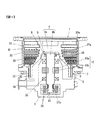
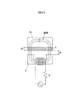
以下、図を参照して本発明を実施するための形態について説明する。図1は本発明の一実施の形態を示す図であり、ターボ分子ポンプのポンプ本体1の概略構成を示す断面図である。ポンプ本体1は不図示のコントロールユニットによって制御される。
Hereinafter, embodiments for carrying out the present invention will be described with reference to the drawings. FIG. 1 is a diagram showing an embodiment of the present invention, and is a cross-sectional view showing a schematic configuration of a
ポンプ本体1は、回転翼41と固定翼31とで構成されるターボポンプ段と、円筒部42とステータ32とで構成されるネジ溝ポンプ段とを有している。ネジ溝ポンプ段においては、ステータ32または円筒部42にネジ溝が形成されている。回転翼41および円筒部42はポンプロータ4aに形成されている。ポンプロータ4aはシャフト4bに締結されている。ポンプロータ4aとシャフト4bとによって回転体ユニット4が構成される。
The pump
軸方向に配置された複数段の回転翼41に対して、複数段の固定翼31が交互に配置されている。各固定翼31は、スペーサリング33を介してベース3上に載置される。ポンプケーシング30をベース3にボルト固定すると、積層されたスペーサリング33がベース3とポンプケーシング30の係止部30aとの間に挟持され、固定翼31が位置決めされる。
A plurality of stages of fixed
シャフト4bは、ベース3に設けられた磁気軸受34,35,36によって非接触支持される。詳細な図示は省略したが、各磁気軸受34〜36は電磁石と変位センサとを備えている。変位センサによりシャフト4bの浮上位置が検出される。シャフト4b、すなわち回転体ユニット4の回転数(1秒当たりの回転数)は、回転センサ43によって検出される。
The
シャフト4bはモータ10により回転駆動される。モータ10は、ベース3に設けられたモータステータ10aと、シャフト4bに設けられたモータロータ10bとから成る。磁気軸受が作動していない時には、シャフト4bは非常用のメカニカルベアリング37a,37bによって支持される。回転体ユニット4がモータ10により高速回転されると、ポンプ吸気口側のガスは、ターボポンプ段(回転翼41、固定翼31)およびネジ溝ポンプ段(円筒部42、ステータ32)により順に排気され、排気ポート38から排出される。
The
ベース3には、ステータ32を温度調整するためのヒータ5および冷却装置7が設けられている。図1に示す例では、冷却装置7として、冷媒が流通する流路が形成された冷却ブロックが設けられている。図示していないが、冷却装置7の冷媒流路には冷媒流入のオンオフを制御する電磁弁が設けられている。ベース3にはベース温度センサ6が設けられている。なお、図1に示す例では、ベース温度センサ6をベース3に設けているがステータ32に設けるようにしても良い。
The
また、ポンプロータ4aの温度はロータ温度センサ8によって検出される。上述したようにポンプロータ4aは磁気浮上されて高速回転するので、ロータ温度センサ8には非接触式の温度センサが用いられる。本実施の形態では、ロータ温度センサ8はインダクタンス式センサであって、ポンプロータ4aに設けられたターゲット9の透磁率の変化をインダクタンスの変化として検出する。ターゲット9は強磁性体で形成されている。
The temperature of the
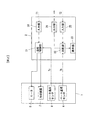
図2は、温度制御装置2を示すブロック図である。ポンプ本体1には、上述したように温度調整用のヒータ5、冷却装置7およびベース温度センサ6と、ポンプロータ4aの温度を検出するためのロータ温度センサ8が設けられている。これらは、温度制御装置2に接続されている。
FIG. 2 is a block diagram showing the
温度制御装置2は、温度制御部21、比較部22,表示部23,入力部24,25および出力部26を備えている。温度制御部21は、ロータ温度センサ8により検出されたロータ温度Trと、入力部24に入力された所定温度T1とに基づいて、ヒータ5による加熱および冷却装置7による冷却を制御する。具体的には、ヒータ5のオンオフ制御、および冷却装置7の冷媒流入のオンオフ制御が行われる。なお、本実施の形態ではヒータ5と冷却装置7とを用いて温調を行うようにしたが、ヒータ5のオンオフのみで温調を行っても良い。
The
比較部22は、ベース温度センサ6により検出されたベース温度Tbと、入力部25に入力された所定温度T2とに基づいて、反応生成物の堆積に関する警報表示を表示部23に表示させる。入力部24,25への所定温度T1,T2の入力方法としては、例えば、オペレータが入力部24,25に設けられた操作部を操作して手動で入力する構成とされる。また、上位のコントローラからの指令によって所定温度T1,T2を設定する構成であっても良い。なお、特に外部より設定されない場合は、T1,T2として予め記憶している標準的な値を適用する。
Based on the base temperature Tb detected by the
(温調動作および警報動作の説明)
次に、温度制御装置2による温調動作および警報動作について詳しく説明する。前述したように、エッチングプロセス等において排気を行うと、反応生成物がポンプ内部に堆積する。特に、ポンプ下流側のステータ32、円筒部42やベース3のガス流路に堆積しやすく、ステータ32および円筒部42への堆積が増大するとステータ32と円筒部42との隙間が堆積物によって狭まり、ステータ32と円筒部42とが接触したり固着したりすることがある。そのため、ヒータ5および冷却装置7を設けてベース部分の温度を制御し、ステータ32、円筒部42やベース3のガス流路への反応生成物の堆積を抑制するようにしている。この温度調整動作については後述する。
(Explanation of temperature control and alarm operation)
Next, the temperature control operation and alarm operation by the
ターボ分子ポンプのポンプロータ4aには一般的にアルミ材が用いられるので、ポンプロータ4aの温度(ロータ温度Tr)には、クリープ歪みに関するアルミ材特有の許容温度がある。ターボ分子ポンプにおいてはポンプロータ4aが高速回転されるので、高速回転状態においてはポンプロータ4aに高い遠心力が作用して高引張応力状態となる。そのような高引張応力状態においてポンプロータ4aの温度が許容温度(例えば、120℃)以上になると、永久歪みが増加するクリープ変形の速度が無視できなくなる。
Since the aluminum material is generally used for the
許容温度以上で運転し続けると、ポンプロータ4aのクリープ歪みが増加してポンプロータ4aの各部の径寸法が増大し、円筒部42とステータ32との隙間や回転翼41と固定翼31との隙間が狭まり、それらが接触する可能性がある。このように、ポンプロータ4aのクリープ歪みを考慮すると、許容温度以下で運転するのが好ましい。一方で、反応生成物の堆積を抑えて堆積物除去のメンテナンス間隔をより長期化するためには、温調によってベース温度Tbをより高く保持するのが好ましい。
If the operation is continued at the allowable temperature or higher, the creep distortion of the
詳細は後述するが、本実施の形態では、ロータ温度センサ8で検出されたロータ温度Trが所定温度または所定温度範囲となるようにヒータ5および冷却装置7を制御することで、クリープ歪みによるポンプロータ4aの寿命の長寿命化を優先した適正温度に保ちつつ、反応生成物堆積に対するメンテナンス時間の長期化を図るようにした。
Although details will be described later, in the present embodiment, the
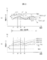
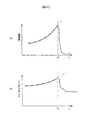
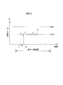
図3は、ロータ温度Trが所定温度T1となるようにベース部の加熱および冷却(すなわち温調)を行った場合の、ロータ温度Trおよびベース温度Tbの短時間における推移の一例を示す図である。ここで短時間とは、数分から数時間の時間範囲を言う。 FIG. 3 is a diagram showing an example of changes in the rotor temperature Tr and the base temperature Tb in a short time when the base portion is heated and cooled (that is, temperature control) so that the rotor temperature Tr becomes the predetermined temperature T1. is there. Here, the short time means a time range from several minutes to several hours.
図3(a)はロータ温度Trの推移を示す図である。上述したように、所定温度T1は、ベース部の温調を行う際のロータ温度Trの制御目標値である。図3(b)の曲線L21,L22,L23はベース温度Tbの推移を示している。曲線L21,L22,L23は排気するガス種が異なる。符号λ1,λ2,λ3はガスの熱伝導率を表しており、λ1>λ2>λ3の大小関係にある。 FIG. 3A is a diagram showing the transition of the rotor temperature Tr. As described above, the predetermined temperature T1 is a control target value of the rotor temperature Tr when the temperature of the base portion is adjusted. Curves L21, L22, and L23 in FIG. 3B show the transition of the base temperature Tb. Curves L21, L22, and L23 differ in the type of gas to be exhausted. Reference numerals λ1, λ2, and λ3 represent the thermal conductivity of the gas, and have a relationship of λ1> λ2> λ3.
ポンプロータ4aはガス中を高速回転して排気するためガスとの摩擦で発熱する。一方で、ポンプロータ4aから固定翼、ステータへ放熱される熱量はガスの熱伝導率に依存し、ガスの熱伝導率が大きいほど放熱量も大きくなる。その結果、ガスの熱伝導率が小さい場合の方がポンプロータ4aからの放熱量が小さく、ロータ温度Trは高くなる。すなわち、同一のガス流量、同一のベース温度Tbに対して、ガスの熱伝導率が小さい場合ほどロータ温度Trが高くなる。
The
本実施の形態では、ロータ温度Trが所定温度T1となるようにベース部の加熱および冷却を制御しているので、ガスの熱伝導率が小さい場合ほどベース温度Tbが低くなる。図3(b)に示す例ではλ1>λ2>λ3なので、ベース温度Tbは熱伝導率λ3の曲線L23が最も低く、曲線L22、L21の順にロータ温度Trが高くなる。 In the present embodiment, since the heating and cooling of the base part are controlled so that the rotor temperature Tr becomes the predetermined temperature T1, the base temperature Tb becomes lower as the thermal conductivity of the gas is lower. In the example shown in FIG. 3B, since λ1> λ2> λ3, the base temperature Tb is the lowest in the curve L23 of the thermal conductivity λ3, and the rotor temperature Tr increases in the order of the curves L22 and L21.
所定温度T1が図2の入力部24に入力されると、入力部24から温度制御部21に所定温度T1が入力される。温度制御部21は、所定温度T1が入力されると、ヒータ5および冷却装置7のオンオフ制御を行うための目標上限温度TU(=T1+ΔT)および目標下限温度TL(=T1−ΔT)を、所定温度T1の上下に設定する。そして、入力された所定温度T1およびロータ温度Trに基づいて、ロータ温度Trが所定温度T1となるようにヒータ5および冷却装置7のオンオフを制御する。
When the predetermined temperature T1 is input to the
図3(a)の時刻t1においてロータ温度Trが目標下限温度TLを上向きに越えたならば、温度制御部21はオン状態であったヒータ5をオフして加熱を停止する。ヒータ5によるベース部分の加熱を停止すると、ベース部(ステータ32)からポンプロータ4aへの熱移動量が小さくなって、ロータ温度Trの上昇率が小さくなる。その後、時刻t2においてロータ温度Trが目標上限温度TUを上向きに越えたならば、温度制御部21は冷却装置7をオンしてベース部の冷却を開始する。冷却によりステータ32の温度が低下すると、ポンプロータ4aからステータ32へ熱が移動し、冷却開始からしばらくするとロータ温度Trが低下し始める。
If the rotor temperature Tr exceeds the target lower limit temperature TL upward at time t1 in FIG. 3A, the
ロータ温度Trが低下し、時刻t3においてロータ温度Trが目標上限温度TUを下向きに越えたならば、温度制御部21は冷却装置7をオフする。その結果、円筒部42からステータ32への熱移動が減少し、ロータ温度Trの低下率が徐々に小さくなる。その後、時刻t4においてロータ温度Trが目標下限温度TLを下向きに越えたならば、温度制御部21はヒータ5をオンしてベース部の加熱を再開する。ヒータ加熱によりステータ32の温度が上昇するとステータ32から円筒部42へ熱が移動し、ロータ温度Trが上昇し始める。このように、ベース部の加熱、冷却によりベース3およびステータ32の温度が上昇、低下すると、それにつれてポンプロータ4aの温度(ロータ温度Tr)も上昇、低下する。
If the rotor temperature Tr decreases and the rotor temperature Tr exceeds the target upper limit temperature TU downward at time t3, the
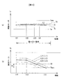
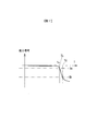
図4は、ロータ温度Trが所定温度T1となるようにベース部の加熱および冷却を行った場合のロータ温度Trおよびベース温度Tbの長時間における推移の一例を示す図である。ここでの長時間とは、数か月から数年の期間を指す。ヒータ5および冷却装置7によりベース部の温調を行うことで反応生成物の堆積は抑制されるが、それでも徐々に堆積が進む。
FIG. 4 is a diagram illustrating an example of a long-term transition of the rotor temperature Tr and the base temperature Tb when the base portion is heated and cooled so that the rotor temperature Tr becomes the predetermined temperature T1. The long time here refers to a period of several months to several years. By controlling the temperature of the base portion by the
ポンプ内に反応生成物が堆積してガス流路が狭くなるにつれて、タービン翼部の圧力が上昇してくる。タービン翼部の圧力が上昇すると、ロータ回転数を定格回転数に維持するのに必要なモータ電流が増加するとともに、ガス排気に伴う発熱が増加する。その結果、ロータ温度が上昇傾向となる。反応生成物堆積によりロータ温度Trが上昇傾向になると、ロータ温度Trが所定温度T1となるように温調を行っているのでベース部の加熱量が減少する。すなわち、反応生成物の堆積の増加に伴ってベース温度Tbが低下する。 As the reaction product accumulates in the pump and the gas flow path becomes narrower, the turbine blade pressure increases. When the turbine blade pressure increases, the motor current required to maintain the rotor rotational speed at the rated rotational speed increases, and heat generation associated with gas exhaust increases. As a result, the rotor temperature tends to increase. When the rotor temperature Tr tends to increase due to the reaction product accumulation, the temperature is adjusted so that the rotor temperature Tr becomes the predetermined temperature T1, so the heating amount of the base portion decreases. That is, the base temperature Tb decreases as the reaction product deposits increase.
図4に示す例では、時刻t11にポンプを使用開始してからしばらくの間は、反応生成物の堆積量がロータ温度Trに影響を及ぼすほどの量でないため、ベース温度Tbはほぼ一定に保たれている。しかし、堆積量がある程度増加した時刻t12以後は、ロータ温度Trの上昇を抑えるためにベース加熱量が減少し、ベース温度が低下し始める。そして、図2の比較部22によってベース温度Tbが所定温度T2以下となったことが検出されると、比較部22はメンテナンスを求める警報信号を表示部23に出力すると共に、出力部26を介して警報信号を外部に出力する。警報信号が表示部23に入力されると、表示部23は警報表示を表示する。
In the example shown in FIG. 4, the base temperature Tb is kept almost constant for a while after the pump is started at time t11, since the amount of reaction product deposited is not so large as to affect the rotor temperature Tr. I'm leaning. However, after time t12 when the deposition amount has increased to some extent, the base heating amount decreases to suppress the increase in the rotor temperature Tr, and the base temperature begins to decrease. When the
さらに、ベース温度Tbが運転可能下限温度Tminに達したことが比較部22によって検出されると、比較部22は警告信号を表示部23に出力すると共に、ポンプ停止信号を出力部26から外部(例えば、ターボ分子ポンプのコントロールユニット)に出力する。表示部23は、警告信号が入力されるとポンプ停止を示す警告表示を表示する。また、ポンプ停止信号がターボ分子ポンプのコントロールユニットに入力されると、ターボ分子ポンプはポンプ停止動作を開始する。
Further, when the
図3,4において、温度Tmaxはターボ分子ポンプの運転可能上限温度であって、ロータ温度Trが運転可能上限温度Tmaxを越えるとポンプロータ4aのクリープ歪みが無視できなくなり寿命低下への影響が大きくなる。そのため、所定温度T1は、ロータ温度Trが運転可能上限温度Tmaxを越えないようにTU<Tmaxのように設定される。ロータ温度Trが運転可能上限温度Tmax以下であれば、クリープ歪みの影響が小さく、ポンプロータ4aのクリープ寿命を所定値以上に保持することができる。
3 and 4, the temperature Tmax is the upper limit temperature at which the turbo molecular pump can be operated. If the rotor temperature Tr exceeds the upper limit temperature Tmax that can be operated, the creep distortion of the
しかしながら、所定温度T1を過度に低く設定すると、温調時のベース温度Tbが所定温度T2以下となってしまい、反応生成物の堆積量が増加してメンテナンス間隔が短くなってしまう。そのため、所定温度T1は、図4(b)に示すように初期状態においてベース温度Tbの曲線L21,L22,L23が所定温度T2よりも高温位置となるように設定するのが好ましい。 However, if the predetermined temperature T1 is set too low, the base temperature Tb at the time of temperature control becomes equal to or lower than the predetermined temperature T2, the amount of accumulated reaction products increases, and the maintenance interval is shortened. Therefore, the predetermined temperature T1 is preferably set so that the curves L21, L22, and L23 of the base temperature Tb are higher than the predetermined temperature T2 in the initial state as shown in FIG. 4B.
図3,4に示す例では、所定温度T1を設定する際の下限値である温度Taは、曲線L23のガスまでを想定した場合の値を示した。温度Taは、排気の可能性がある複数のガス種の内、熱伝導率が最も低いガス種のガス流量を定めて、ロータ温度Trが温度Taとなったときの曲線L23(ベース温度Tb)の位置が所定温度T2よりも若干高温側となるように設定されている。このように、温度Taは、ベース温度Tbが所定温度T2を下回らないようにするためのロータ温度Trの下限値である。 In the example shown in FIGS. 3 and 4, the temperature Ta, which is the lower limit value when setting the predetermined temperature T <b> 1, indicates a value when assuming gas up to the curve L <b> 23. The temperature Ta is a curve L23 (base temperature Tb) when the gas temperature of the gas type having the lowest thermal conductivity among a plurality of gas types that can be exhausted is determined and the rotor temperature Tr becomes the temperature Ta. Is set to be slightly higher than the predetermined temperature T2. Thus, the temperature Ta is a lower limit value of the rotor temperature Tr for preventing the base temperature Tb from falling below the predetermined temperature T2.
所定温度T1の下限値は、ベース温度Tbが所定温度T2を下回らない下限温度であり、図3(a)は所定温度T1を下限値に設定した場合を示す。一方、図3(a)の曲線L1’は、所定温度T1を上限値に設定した場合を示す。この場合、ロータ温度Trは運転可能上限温度Tmax以下に制御される。すなわち、所定温度T1は図3(a)の符号Aで示す範囲に設定される。曲線L1の温度変化幅を2ΔT1とした場合、温度範囲AはTa+ΔT1≦T1≦Tmax−ΔT1となる。図3(b)に示すように3種類の曲線L21,L22,L23の全てが所定温度T2を上回るようにするためには、下限値TaをTa=T1−ΔT1のように設定すれば良い。 The lower limit value of the predetermined temperature T1 is a lower limit temperature at which the base temperature Tb does not fall below the predetermined temperature T2, and FIG. 3A shows a case where the predetermined temperature T1 is set to the lower limit value. On the other hand, a curve L1 'in FIG. 3A shows a case where the predetermined temperature T1 is set to the upper limit value. In this case, the rotor temperature Tr is controlled to be lower than the operable upper limit temperature Tmax. That is, the predetermined temperature T1 is set in the range indicated by the symbol A in FIG. When the temperature change width of the curve L1 is 2ΔT1, the temperature range A is Ta + ΔT1 ≦ T1 ≦ Tmax−ΔT1. As shown in FIG. 3B, in order for all of the three types of curves L21, L22, and L23 to exceed the predetermined temperature T2, the lower limit value Ta may be set as Ta = T1−ΔT1.
なお、予め想定したガス種よりも熱伝導率が低いガス種が排気される場合、あるいは、ガス種に関係なく標準的な所定温度T1に設定したとしても、結果的に初期状態からベース部温度が所定温度T2を下回ることがあり得るが、そのような場合には、改めて所定温度T1の値を下げる設定変更を行えば良い。 Note that, when a gas type having a lower thermal conductivity than the gas type assumed in advance is exhausted, or even when the standard predetermined temperature T1 is set regardless of the gas type, as a result, the base portion temperature is changed from the initial state. May fall below the predetermined temperature T2, but in such a case, the setting may be changed to lower the value of the predetermined temperature T1 again.
所定値T1の設定方法としては、例えば、ロータ寿命を最優先とする値T1=Ta+ΔT1が所定値T1の初期値として予め設定されていて、Ta+ΔT1≦T1≦Tmax−ΔT1の範囲の所望の値をユーザが入力部24から入力できる構成としても良い。ユーザは、ロータ寿命とメンテナンス期間とのどちらにどの程度のウェイトを付与するかに応じて所定温度T1を設定することができる。つまり、ロータ寿命とメンテナンス期間に対して適切なトレードオフをかけることができる。また、所定温度T2についても予め初期値が設定されていて、ユーザが所望の値を入力部25から入力できるような構成とする。この場合の所定温度T2の初期値としては、例えば、従来のベース温度に対して目標温度を設定して温調を行う場合の目標温度と同程度の温度が設定される。
As a method for setting the predetermined value T1, for example, a value T1 = Ta + ΔT1 giving the highest priority to the life of the rotor is preset as an initial value of the predetermined value T1, and a desired value in the range of Ta + ΔT1 ≦ T1 ≦ Tmax−ΔT1 is set. It is good also as a structure which a user can input from the
また、所定温度T2として、反応生成物の昇華温度またはその近傍温度を用いても良い。ベース温度Tbが昇華温度である所定温度T2を下回ると、反応生成物の堆積速度が急速に速まるので、メンテナンスを促す警報表示を行う。 Further, as the predetermined temperature T2, a sublimation temperature of the reaction product or a temperature in the vicinity thereof may be used. When the base temperature Tb falls below a predetermined temperature T2, which is a sublimation temperature, the deposition rate of the reaction product is rapidly increased.
運転可能下限温度Tminとしては、一例として、反応生成物の堆積が著しくなって円筒部42とステータ32との接触等の可能性が高くなるベース温度があるが、このベース温度を厳密に決定するのは難しく、プロセスの状況やポンプ状況によって大きく影響される。そのため、目安として、所定温度T2に対して、温度幅Bが10℃程度以下となるように設定される。もちろん、実際のプロセス条件で実験やシミュレーションを行って温度Tminを決定しても構わない。
As an example of the operable lower limit temperature Tmin, there is a base temperature at which the reaction product is remarkably deposited and the possibility of contact between the
(ロータ温度センサ8の説明)
ロータ温度センサ8は、ポンプロータ4aの温度を非接触で検出する。そのような非接触センサとしては種々のものがあるが、本実施の形態のロータ温度センサ8では、ポンプロータ4aに設けられた強磁性体のターゲット9の透磁率の変化をインダクタンスの変化として検出する。
(Description of rotor temperature sensor 8)
The
図5はロータ温度センサ8の温度検出原理を説明する図であり、ロータ温度センサ8とターゲット9の作る磁気回路の模式図である。ロータ温度センサ8の構造は、珪素鋼板などの透磁率の大きなコアの周囲にコイルを巻いたものである。ロータ温度センサ8のコイルには搬送波として一定周波数・一定電圧の高周波電圧が印加され、ロータ温度センサ8からターゲット9に向けて高周波磁界が形成される。
FIG. 5 is a diagram for explaining the temperature detection principle of the
ターゲット9には、キュリー温度Tcがポンプロータ4aの運転可能上限温度Tmaxとほぼ同一か、または、それに近い温度を有する磁性体材料を用いる。例えば、アルミの場合の運転可能上限温度Tmaxは110℃〜130℃程度であり、キュリー温度Tcが120℃程度の磁性体材料としては、ニッケル・亜鉛フェライトやマンガン・亜鉛フェライト等がある。
The
図6は、キュリー温度Tcにおける透磁率変化およびインダクタンス変化の一例を示す図である。ロータ温度上昇によりターゲット9の温度が上昇してキュリー温度Tcを越えると、図6(a)の実線で示すように、ターゲット9の透磁率が真空の透磁率程度まで急激に低下する。図6(a)は典型的な磁性体であるフェライトの場合の透磁率変化を示したものであり、常温における透磁率はキュリー温度付近の透磁率よりも低く、温度上昇とともに上昇してキュリー温度Tcを越えると急激に低下する。ロータ温度センサ8が形成する磁界中でターゲット9の透磁率が変化すると、ロータ温度センサ8のインダクタンスが変化することになる。その結果、搬送波は振幅変調され、ロータ温度センサ8から出力される振幅変調された搬送波を検波・整流することにより、透磁率の変化に相当する信号変化を検出することができる。
FIG. 6 is a diagram illustrating an example of permeability change and inductance change at the Curie temperature Tc. When the temperature of the
ロータ温度センサ8のコア材料はフェライト等の磁性体が用いられるが、この透磁率がエアギャップの透磁率に比べてそれを無視できる程度に大きく、また、漏れ磁束が無視できる場合には、インダクタンスLと寸法d,d1との関係は近似的に次式(1)のように表される。なお、Nはコイルの巻き数、Sはターゲット9と対向するセンサコアの断面積、dはエアギャップ、d1はターゲット9の厚さ、μ1はターゲット9の透磁率であり、エアギャップの透磁率は真空の透磁率μ0に等しいとする。
L=N2/{d1/(μ1・S)+d/(μ0・S)} …(1)
The core material of the
L = N 2 / {d1 / (μ1 · S) + d / (μ0 · S)} (1)
ロータ温度Trがキュリー温度Tcよりも低い温度のときには、ターゲット9の透磁率は真空の透磁率に比べて十分に大きい。そのため、d1/(μ1・S)はd/(μ0・S)に比べて無視できるほどに小さくなり、式(1)は次式(2)のように近似できる。
L=N2・μ0・S/d …(2)
When the rotor temperature Tr is lower than the Curie temperature Tc, the magnetic permeability of the
L = N 2 · μ0 · S / d (2)
一方、ロータ温度Trがキュリー温度Tcよりも上昇すると、近似的にμ1=μ0となる。そのため、この場合には式(1)は次式(3)のように表される。
L=N2・μ0・S/(d+d1) …(3)
On the other hand, when the rotor temperature Tr rises above the Curie temperature Tc, μ1 = μ0 is approximately obtained. Therefore, in this case, the expression (1) is expressed as the following expression (3).
L = N 2 · μ0 · S / (d + d1) (3)
すなわち、エアギャップがdから(d+d1)に変化したことに相当し、それに応じてロータ温度センサ8のインダクタンスが変化することになる。このインダクタンス変化を検出することにより、ロータ温度がキュリー温度Tc以上となったか否かをモニタすることができる。
That is, this corresponds to the change of the air gap from d to (d + d1), and the inductance of the
図6(a)に示した透磁率の変化は、ロータ温度センサ8のコイルによってインダクタンスの変化に変換されるが、インダクタンスは図6(b)の実線のように変化する。インダクタンスも透磁率の変化と同様の変化をするが、変化の割合が透磁率に比べて若干小さくなり、上下に圧縮されたような変化となる。
The change in magnetic permeability shown in FIG. 6A is converted into a change in inductance by the coil of the
図6(a),(b)の二点差線は、強磁性体のターゲット9とは別の純鉄のターゲットの透磁率変化およびインダクタンス変化を示したものである。純鉄ターゲットのキュリー温度Tcはターゲット9のキュリー温度Tcに比して十分に高いので、図6(a),(b)に示す温度範囲では、透磁率およびインダクタンスは温度上昇とともに単純に増加している。このような純鉄ターゲットをポンプロータ4aに設けておき、ターゲット9のインダクタンス信号と純鉄ターゲットのインダクタンス信号との差分信号を取ると、図7に示すような差分信号となる。
6 (a) and 6 (b) show the magnetic permeability change and inductance change of a pure iron target different from the
図7は、温度TU,TLの設定方法を説明する図である。図7のような差分信号に対して2つの閾値Va,Vbを設定すると、ロータ温度TrがTL以上のときに差分信号は閾値Va以下となり、ロータ温度TrがTU以上のときに差分信号は閾値Vb以下となる。 FIG. 7 is a diagram illustrating a method for setting temperatures TU and TL. When two threshold values Va and Vb are set for the difference signal as shown in FIG. 7, the difference signal is equal to or lower than the threshold value Va when the rotor temperature Tr is equal to or higher than TL, and the difference signal is equal to the threshold value when the rotor temperature Tr is equal to or higher than TU. Vb or less.
なお、キュリー温度Tc付近における透磁率変化が急激すぎて図7のように2つの温度閾値(TL,TU)を取得することが困難な場合には、例えば、図8のようにキュリー温度Tc1,Tc2の異なる2つのターゲットを用いても良い。キュリー温度Tc1(<Tc2)のターゲットにより温度閾値TLを取得し、キュリー温度Tc2のターゲットにより温度閾値TUを取得する。 In the case where it is difficult to obtain two temperature threshold values (TL, TU) as shown in FIG. 7 due to a sudden change in permeability in the vicinity of the Curie temperature Tc, for example, as shown in FIG. Two targets having different Tc2 may be used. The temperature threshold value TL is acquired from the target having the Curie temperature Tc1 (<Tc2), and the temperature threshold value TU is acquired from the target having the Curie temperature Tc2.
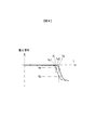
また、図3に示す例では、所定温度T1を挟んで2つの温度閾値(TU、TL)を設けてヒータ5および冷却装置7のオンオフ制御を行うようにしたが、図9に示すように一つの温度閾値を設けてオンオフ制御を行うようにしても良い。この場合には、所定温度T1は下限値Taに等しく設定される。時刻t1においてロータ温度Trが所定温度T1を上向きに越えたならば、ヒータ5をオフして冷却装置7をオンする。その結果、ベース温度Tbが低下してロータ温度Trも低下する。その後、時刻t2においてロータ温度Trが所定温度T1を下向きに越えたならば、ヒータ5をオンし、冷却装置7をオフする。その結果、ベース温度Tbが上昇してロータ温度Trも上昇する。
In the example shown in FIG. 3, two temperature thresholds (TU, TL) are provided across the predetermined temperature T1, and the
上述した実施の形態では、ロータ温度Trが所定温度T1となるようにヒータ5および冷却装置7のオンオフ制御を行うようにした。しかし、ロータ温度Trが所定の温度範囲内に制御されるようにヒータ5および冷却装置7のオンオフ制御を行うようにしても良い。
In the above-described embodiment, on / off control of the
例えば、図8の場合と同様に、キュリー温度の異なる2つの強磁性体ターゲットを用いてロータ温度Trが温度TU,TLとなるタイミングを検出する。そして、ロータ温度Trが温度TUを越える場合にはポンプベース部の加熱量を低下させ、ロータ温度Trが温度TLを下回る場合にはポンプベース部の加熱量を増加させることで、ロータ温度TrをTL以上TU以下の温度範囲に収める。温度TUは運転可能上限温度Tmax以下に設定し、温度TLは図3の温度Taよりも高く設定される。それにより、ロータ温度Trが運転可能上限温度Tmax以下となりロータ寿命の長期化が図れ、かつ、ベース温度Tbが所定温度T2よりも高く保持されて反応生成物の堆積が抑えられる。 For example, as in the case of FIG. 8, the timing at which the rotor temperature Tr becomes the temperatures TU and TL is detected using two ferromagnetic targets having different Curie temperatures. When the rotor temperature Tr exceeds the temperature TU, the heating amount of the pump base portion is reduced. When the rotor temperature Tr is lower than the temperature TL, the heating amount of the pump base portion is increased, thereby reducing the rotor temperature Tr. The temperature is in the range of TL to TU. The temperature TU is set to be equal to or lower than the operable upper limit temperature Tmax, and the temperature TL is set to be higher than the temperature Ta in FIG. Thereby, the rotor temperature Tr becomes equal to or lower than the operable upper limit temperature Tmax, and the life of the rotor can be prolonged, and the base temperature Tb is kept higher than the predetermined temperature T2 and the deposition of reaction products is suppressed.
ポンプ稼働時間が長期に及ぶと反応生成物の堆積量が増加し、図4(a)の場合と同様にベース温度Tbが低下する。そして、ベース温度Tbが所定温度T2以下となったならば、メンテナンスの警報を発生する。さらに、ベース温度Tbが運転可能下限温度Tminに達すると、警告信号を表示部23に出力すると共に、ポンプ停止信号を出力部26から出力する。
When the pump operation time is extended for a long time, the amount of accumulated reaction products increases, and the base temperature Tb decreases as in the case of FIG. When the base temperature Tb becomes equal to or lower than the predetermined temperature T2, a maintenance alarm is generated. Further, when the base temperature Tb reaches the operable lower limit temperature Tmin, a warning signal is output to the
(1)上述のように、本実施の形態の温度制御装置2は、ポンプベース部であるベース3に設けられたステータ32と、ステータ32に対して回転駆動されるポンプロータ4aと、ベース3を加熱するヒータ5と、ベース3の温度を検出するベース温度センサ6と、ポンプロータ4aの温度に相当する物理量である温度相当量を検出するロータ温度センサ8とを備えるターボ分子ポンプの、温度制御装置であって、ロータ温度センサ8の検出値に基づいてヒータ5によるベース3の加熱を制御する温度制御部21と、ベース温度センサ6の検出温度が所定閾値(例えば、所定温度T2)以下の場合に警報を報知する報知部としての表示部23および出力部26と、を備える。
(1) As described above, the
温度制御部21は、ロータ温度センサ8の検出値に基づいてヒータ5によるベース3の加熱を制御するので、ポンプロータ4aのロータ温度Trが運転可能上限温度Tmaxを越えないようにヒータ加熱を行うことが可能となる。反応生成物の堆積によりロータ温度Trが上昇傾向となった場合、上述のような加熱制御を行うとロータ温度上昇が抑えられてベース温度Tbが徐々に低下する傾向となる。その結果、反応生成物の堆積量の増加をベース温度Tbの低下として検出することができ、ベース温度Trが所定温度T2以下となったときに、反応生成物除去のメンテナンスタイミングを報知する。それにより、反応生成物堆積による不都合の発生、例えば、ポンプロータ4aとステータ32との固着や、回転中のポンプロータ4aのステータ32への接触を予防することができる。
Since the
(2)さらに、ロータ温度センサ8の検出値が所定目標値である所定温度T1となるようにヒータ5によるベース3の加熱を制御するのが好ましい。このような制御を行うことにより、ロータ温度Trを運転可能上限温度Tmaxに近づけることが可能となり、ベース温度Tbを可能な限り高温とすることができる。その結果、反応生成物除去のメンテナンス間隔を可能な限り長期化することができる。
(2) Further, it is preferable to control the heating of the
(3)また、上述した実施形態では、温度制御装置2は、ポンプベース部であるベース3に設けられたステータと、ステータに対して回転駆動されるポンプロータ4aと、ベース3を加熱するヒータ5と、ポンプロータ4aの温度に相当する物理量である温度相当量を検出するロータ温度センサ8とを備えるターボ分子ポンプの、温度制御装置であって、ロータ温度センサ8の検出値が所定目標値(例えば、所定温度T1)となるようにベース3の加熱を制御する構成となっている。
(3) In the above-described embodiment, the
このようにロータ温度Trが所定目標値となるようにベース3の加熱を制御する構成では、ロータ温度Trを運転可能上限温度Tmaxに可能な限り近づけることで、ベース温度Tbをより高く保持することができる。そのため、ロータ寿命を管理しつつ反応生成物の堆積を可能な限り低減することができ、ターボ分子ポンプにおける、ロータ寿命の長寿命化と反応生成物除去のメンテナンス期間の長期化との間のトレードオフを最適化することができる。
Thus, in the configuration in which the heating of the
なお、上述した特開平10−266991号公報に記載の発明では、ロータ温度に基づく推定演算によりベース温度目標値を設定し、そのベース温度目標値となるようにベース加熱を制御している。このようにロータ温度からベース温度目標値を推定する構成では、推定演算が複雑となる。さらに、ベース温度をベース温度目標値に制御することでロータ温度が高温となるのを防止しているので、本実施の形態に比べてロータ温度制御精度の点で劣っている。 In the invention described in Japanese Patent Laid-Open No. 10-266991 described above, the base temperature target value is set by the estimation calculation based on the rotor temperature, and the base heating is controlled so as to be the base temperature target value. Thus, in the configuration in which the base temperature target value is estimated from the rotor temperature, the estimation calculation is complicated. Furthermore, since the rotor temperature is prevented from becoming high by controlling the base temperature to the base temperature target value, the rotor temperature control accuracy is inferior to the present embodiment.
(4)ロータ温度検出部は、ポンプロータ4aに設けられた強磁性体のターゲット9と、ターゲット9に対して対向するように配置され、ターゲット9の透磁率変化を検出するロータ温度センサ8とを備え、ターゲット9のキュリー点近傍の透磁率変化に基づいてポンプロータ4aの温度を検出する。ロータ温度検出部をこのような構成とすることで、排気するガスの種類に依存することなくロータ温度Trを検出することができる。
(4) The rotor temperature detector is provided with a
なお、ロータ温度Trを非接触で検出する方法としては、上述したように強磁性体のキュリー点における透磁率の変化を利用するものに限らず種々のものがある。例えば、特開平10−266991号公報に記載されているように、回転翼の浮上方向の長さの熱膨張前後の変化量と、回転翼の主軸の浮上方向長さの熱膨張前後の変化量とに基づいて、回転翼の温度を演算により推定しても良い。 As described above, the method for detecting the rotor temperature Tr in a non-contact manner is not limited to the method using the change in the magnetic permeability at the Curie point of the ferromagnetic material. For example, as described in Japanese Patent Laid-Open No. 10-266991, the amount of change in the length of the rotor blade in the flying direction before and after thermal expansion and the amount of change in the length of the rotor blade main shaft in the flying direction before and after thermal expansion Based on the above, the temperature of the rotor blades may be estimated by calculation.
ところで、特開平10−266991号公報には、吸気口におけるガスの温度と排気口におけるガスの温度との温度差に基づいて回転翼の温度を推定する構成が記載されているが、この場合には、排気しているガスの種類すなわちガスの熱伝導率を特定する必要があり、ガス種が不明であると温度推定に誤差が生じてしまう。 Incidentally, Japanese Patent Laid-Open No. 10-266991 discloses a configuration for estimating the temperature of the rotor blades based on the temperature difference between the temperature of the gas at the intake port and the temperature of the gas at the exhaust port. Needs to specify the type of gas being exhausted, that is, the thermal conductivity of the gas, and if the gas type is unknown, an error occurs in temperature estimation.
一方、上述した強磁性体のキュリー点における透磁率変化を利用する温度検出方法の場合、ガス種に依存せずにロータ温度を検出することができるので、ロータ寿命を適切に管理することができる。 On the other hand, in the case of the temperature detection method using the magnetic permeability change at the Curie point of the ferromagnetic material described above, the rotor temperature can be detected without depending on the gas type, so that the rotor life can be appropriately managed. .
(5)また、図2に示す構成では、温度制御装置2をターボ分子ポンプとは別に設け、ポンプ側からロータ温度Trに相当する物理量である温度相当量と、ベース3のベース温度Tbとを取得し、温度制御装置2の温度制御部21によりヒータ5および冷却装置7のオンオフを制御するようにした。しかし、図10に示すようにターボ分子ポンプのコントローラユニット100に温度制御装置2の機能を内蔵するようにしても良い。コントローラユニット100には、ポンプ本体1のモータ10を駆動制御するモータ制御部101と、磁気軸受34,35および36に電磁石電流を供給する軸受制御部102が設けられている。
(5) In the configuration shown in FIG. 2, the
上記では、種々の実施の形態および変形例を説明したが、本発明はこれらの内容に限定されるものではない。本発明の技術的思想の範囲内で考えられるその他の態様も本発明の範囲内に含まれる。 Although various embodiments and modifications have been described above, the present invention is not limited to these contents. Other embodiments conceivable within the scope of the technical idea of the present invention are also included in the scope of the present invention.
1…ポンプ本体、2…温度制御装置、3…ベース、4…回転体ユニット、4a…ポンプロータ、4b…シャフト、5…ヒータ、6…ベース温度センサ、7…冷却装置、8…ロータ温度センサ、9…ターゲット、10…モータ、21…温度制御部、22…比較部、23…表示部、24,25…入力部、26…出力部、31…固定翼、32…ステータ、34,35,36…磁気軸受、41…回転翼、42…円筒部、T1,T2…所定温度
DESCRIPTION OF
Claims (5)
前記ステータに対して回転駆動されるロータと、
前記ポンプベース部を加熱する加熱部と、
前記ポンプベース部の温度を検出するベース温度検出部と、
前記ロータの温度に相当する物理量である温度相当量を検出するロータ温度検出部とを備えるターボ分子ポンプの、温度制御装置であって、
前記ロータ温度検出部の検出値に基づいて前記加熱部による前記ポンプベース部の加熱を制御する加熱制御部と、
前記ベース温度検出部の検出温度が所定閾値以下の場合に警報を報知する報知部と、を備える温度制御装置。 A stator provided in the pump base,
A rotor that is rotationally driven with respect to the stator;
A heating unit for heating the pump base unit;
A base temperature detection unit for detecting the temperature of the pump base unit;
A temperature control device of a turbo molecular pump comprising a rotor temperature detection unit that detects a temperature equivalent amount that is a physical amount corresponding to the temperature of the rotor,
A heating control unit that controls heating of the pump base unit by the heating unit based on a detection value of the rotor temperature detection unit;
A temperature control apparatus comprising: a notification unit that issues a warning when a temperature detected by the base temperature detection unit is equal to or lower than a predetermined threshold.
前記加熱制御部は、前記ロータ温度検出部の検出値が所定目標値となるように前記加熱部による前記ポンプベース部の加熱を制御する、温度制御装置。 The temperature control device according to claim 1,
The heating control unit is a temperature control device that controls heating of the pump base unit by the heating unit such that a detection value of the rotor temperature detection unit becomes a predetermined target value.
前記ステータに対して回転駆動されるロータと、
前記ポンプベース部を加熱する加熱部と、
前記ロータの温度に相当する物理量である温度相当量を検出するロータ温度検出部とを備えるターボ分子ポンプの、温度制御装置であって、
前記ロータ温度検出部の検出値が所定目標値となるように前記加熱部による前記ポンプベース部の加熱を制御する、温度制御装置。 A stator provided in the pump base,
A rotor that is rotationally driven with respect to the stator;
A heating unit for heating the pump base unit;
A temperature control device of a turbo molecular pump comprising a rotor temperature detection unit that detects a temperature equivalent amount that is a physical amount corresponding to the temperature of the rotor,
A temperature control device that controls heating of the pump base by the heating unit such that a detection value of the rotor temperature detection unit becomes a predetermined target value.
前記ロータ温度検出部は、前記ロータに設けられた強磁性体ターゲットと、前記強磁性体ターゲットに対して対向するように配置され、前記強磁性体ターゲットの透磁率変化を検出するセンサとを備え、前記強磁性体ターゲットのキュリー点近傍の透磁率変化に基づいて前記ロータの温度を検出する、温度制御装置。 In the temperature control device according to any one of claims 1 to 3,
The rotor temperature detection unit includes a ferromagnetic target provided in the rotor, and a sensor that is disposed so as to face the ferromagnetic target and detects a change in permeability of the ferromagnetic target. A temperature control device that detects the temperature of the rotor based on a magnetic permeability change in the vicinity of the Curie point of the ferromagnetic target.
前記ステータに対して回転駆動されるロータと、
前記ポンプベース部を加熱する加熱部と、
前記ポンプベース部の温度を検出するベース温度検出部と、
前記ロータの温度に相当する物理量である温度相当量を検出するロータ温度検出部と、
請求項1から請求項4までのいずれか一項に記載の温度制御装置と、を備えるターボ分子ポンプ。 A stator provided in the pump base,
A rotor that is rotationally driven with respect to the stator;
A heating unit for heating the pump base unit;
A base temperature detection unit for detecting the temperature of the pump base unit;
A rotor temperature detection unit that detects a temperature equivalent amount that is a physical quantity corresponding to the temperature of the rotor;
A turbo molecular pump comprising: the temperature control device according to any one of claims 1 to 4.
Priority Applications (3)
| Application Number | Priority Date | Filing Date | Title |
|---|---|---|---|
| JP2016050292A JP6705228B2 (en) | 2016-03-14 | 2016-03-14 | Temperature controller and turbo molecular pump |
| CN201611191535.7A CN107191388B (en) | 2016-03-14 | 2016-12-21 | Temperature Controls and Turbomolecular Pumps |
| US15/392,524 US10344770B2 (en) | 2016-03-14 | 2016-12-28 | Temperature control device and turbo-molecular pump |
Applications Claiming Priority (1)
| Application Number | Priority Date | Filing Date | Title |
|---|---|---|---|
| JP2016050292A JP6705228B2 (en) | 2016-03-14 | 2016-03-14 | Temperature controller and turbo molecular pump |
Publications (2)
| Publication Number | Publication Date |
|---|---|
| JP2017166360A true JP2017166360A (en) | 2017-09-21 |
| JP6705228B2 JP6705228B2 (en) | 2020-06-03 |
Family
ID=59787812
Family Applications (1)
| Application Number | Title | Priority Date | Filing Date |
|---|---|---|---|
| JP2016050292A Active JP6705228B2 (en) | 2016-03-14 | 2016-03-14 | Temperature controller and turbo molecular pump |
Country Status (3)
| Country | Link |
|---|---|
| US (1) | US10344770B2 (en) |
| JP (1) | JP6705228B2 (en) |
| CN (1) | CN107191388B (en) |
Cited By (1)
| Publication number | Priority date | Publication date | Assignee | Title |
|---|---|---|---|---|
| JP2020012423A (en) * | 2018-07-19 | 2020-01-23 | エドワーズ株式会社 | Vacuum pump |
Families Citing this family (6)
| Publication number | Priority date | Publication date | Assignee | Title |
|---|---|---|---|---|
| JP6583122B2 (en) * | 2016-04-22 | 2019-10-02 | 株式会社島津製作所 | Monitoring device and vacuum pump |
| CN109611345B (en) * | 2018-11-30 | 2020-01-10 | 珠海格力电器股份有限公司 | Multi-operating-condition design method and device for centrifugal rotary machine |
| CN114427539B (en) * | 2020-10-29 | 2024-06-07 | 株式会社岛津制作所 | Turbomolecular pumps |
| TWI757158B (en) * | 2021-04-21 | 2022-03-01 | 致揚科技股份有限公司 | High efficiency turbomolecular pump device |
| CN114320989B (en) * | 2021-12-31 | 2022-12-02 | 北京中科科仪股份有限公司 | Molecular pump temperature measuring device, temperature measuring method and temperature measuring device of running part |
| FR3147334B1 (en) * | 2023-03-30 | 2025-03-14 | Pfeiffer Vacuum | Method for controlling the operating parameters of a turbomolecular vacuum pump |
Citations (5)
| Publication number | Priority date | Publication date | Assignee | Title |
|---|---|---|---|---|
| JPH10266991A (en) * | 1997-01-22 | 1998-10-06 | Seiko Seiki Co Ltd | Turbo molecular pump |
| JP2006017089A (en) * | 2004-07-05 | 2006-01-19 | Shimadzu Corp | Temperature control device for turbo molecular pump |
| JP2009013825A (en) * | 2007-07-03 | 2009-01-22 | Shimadzu Corp | Vacuum pump |
| JP2011080407A (en) * | 2009-10-07 | 2011-04-21 | Shimadzu Corp | Vacuum pump |
| WO2014045438A1 (en) * | 2012-09-24 | 2014-03-27 | 株式会社島津製作所 | Turbomolecular pump |
Family Cites Families (11)
| Publication number | Priority date | Publication date | Assignee | Title |
|---|---|---|---|---|
| DE10114969A1 (en) * | 2001-03-27 | 2002-10-10 | Leybold Vakuum Gmbh | Turbo molecular pump |
| JP2003254284A (en) * | 2002-03-05 | 2003-09-10 | Boc Edwards Technologies Ltd | Pump device |
| JP2003269369A (en) * | 2002-03-13 | 2003-09-25 | Boc Edwards Technologies Ltd | Vacuum pump |
| JP4525267B2 (en) | 2004-09-17 | 2010-08-18 | 株式会社島津製作所 | Vacuum pump |
| US20080131288A1 (en) * | 2006-11-30 | 2008-06-05 | Shimadzu Corporation | Vacuum pump |
| US7965054B2 (en) * | 2007-07-26 | 2011-06-21 | Shimadzu Corporation | Vacuum pump |
| EP2108930A1 (en) * | 2008-04-09 | 2009-10-14 | VARIAN S.p.A. | Contact-less device for measuring operating parameters of rotors of high-speed rotary machines |
| KR101750572B1 (en) * | 2009-08-21 | 2017-06-23 | 에드워즈 가부시키가이샤 | Vacuum pump |
| JP6484919B2 (en) * | 2013-09-24 | 2019-03-20 | 株式会社島津製作所 | Turbo molecular pump |
| JP6287475B2 (en) * | 2014-03-28 | 2018-03-07 | 株式会社島津製作所 | Vacuum pump |
| JP6398337B2 (en) * | 2014-06-04 | 2018-10-03 | 株式会社島津製作所 | Turbo molecular pump |
-
2016
- 2016-03-14 JP JP2016050292A patent/JP6705228B2/en active Active
- 2016-12-21 CN CN201611191535.7A patent/CN107191388B/en active Active
- 2016-12-28 US US15/392,524 patent/US10344770B2/en active Active
Patent Citations (5)
| Publication number | Priority date | Publication date | Assignee | Title |
|---|---|---|---|---|
| JPH10266991A (en) * | 1997-01-22 | 1998-10-06 | Seiko Seiki Co Ltd | Turbo molecular pump |
| JP2006017089A (en) * | 2004-07-05 | 2006-01-19 | Shimadzu Corp | Temperature control device for turbo molecular pump |
| JP2009013825A (en) * | 2007-07-03 | 2009-01-22 | Shimadzu Corp | Vacuum pump |
| JP2011080407A (en) * | 2009-10-07 | 2011-04-21 | Shimadzu Corp | Vacuum pump |
| WO2014045438A1 (en) * | 2012-09-24 | 2014-03-27 | 株式会社島津製作所 | Turbomolecular pump |
Cited By (2)
| Publication number | Priority date | Publication date | Assignee | Title |
|---|---|---|---|---|
| JP2020012423A (en) * | 2018-07-19 | 2020-01-23 | エドワーズ株式会社 | Vacuum pump |
| JP7164981B2 (en) | 2018-07-19 | 2022-11-02 | エドワーズ株式会社 | Vacuum pump |
Also Published As
| Publication number | Publication date |
|---|---|
| CN107191388A (en) | 2017-09-22 |
| US10344770B2 (en) | 2019-07-09 |
| CN107191388B (en) | 2021-06-18 |
| US20170260999A1 (en) | 2017-09-14 |
| JP6705228B2 (en) | 2020-06-03 |
Similar Documents
| Publication | Publication Date | Title |
|---|---|---|
| JP6705228B2 (en) | Temperature controller and turbo molecular pump | |
| CN102472288B (en) | Vacuum pump | |
| JP3057486B2 (en) | Turbo molecular pump | |
| CN104819158B (en) | turbomolecular pump | |
| JP6583122B2 (en) | Monitoring device and vacuum pump | |
| CN112219034B (en) | Vacuum pump and temperature control device | |
| US12196225B2 (en) | Vacuum pump | |
| JP2005083316A (en) | Motor control system and vacuum pump mounting the same | |
| JP7408618B2 (en) | Vacuum pump and control device | |
| JP4673011B2 (en) | Temperature control device for turbo molecular pump | |
| CN113348305A (en) | Vacuum pump and control device for vacuum pump | |
| JP5333359B2 (en) | Vacuum pump | |
| JP4965596B2 (en) | Turbo type vacuum pump | |
| JP2003278692A (en) | Vacuum pump | |
| US12066029B2 (en) | Vacuum pump and controller | |
| JP4882558B2 (en) | Turbo molecular pump | |
| JP2004116328A (en) | Vacuum pump | |
| JP7668765B2 (en) | Vacuum pump, control device and control method | |
| US12378967B2 (en) | Vacuum pump | |
| CN121013944A (en) | Vacuum pump, control device and heating time control method |
Legal Events
| Date | Code | Title | Description |
|---|---|---|---|
| A621 | Written request for application examination |
Free format text: JAPANESE INTERMEDIATE CODE: A621 Effective date: 20180911 |
|
| A977 | Report on retrieval |
Free format text: JAPANESE INTERMEDIATE CODE: A971007 Effective date: 20190725 |
|
| A131 | Notification of reasons for refusal |
Free format text: JAPANESE INTERMEDIATE CODE: A131 Effective date: 20190730 |
|
| A521 | Request for written amendment filed |
Free format text: JAPANESE INTERMEDIATE CODE: A523 Effective date: 20190920 |
|
| RD03 | Notification of appointment of power of attorney |
Free format text: JAPANESE INTERMEDIATE CODE: A7423 Effective date: 20190920 |
|
| A131 | Notification of reasons for refusal |
Free format text: JAPANESE INTERMEDIATE CODE: A131 Effective date: 20200107 |
|
| A521 | Request for written amendment filed |
Free format text: JAPANESE INTERMEDIATE CODE: A523 Effective date: 20200303 |
|
| TRDD | Decision of grant or rejection written | ||
| A01 | Written decision to grant a patent or to grant a registration (utility model) |
Free format text: JAPANESE INTERMEDIATE CODE: A01 Effective date: 20200414 |
|
| A61 | First payment of annual fees (during grant procedure) |
Free format text: JAPANESE INTERMEDIATE CODE: A61 Effective date: 20200427 |
|
| R151 | Written notification of patent or utility model registration |
Ref document number: 6705228 Country of ref document: JP Free format text: JAPANESE INTERMEDIATE CODE: R151 |