JP2017166341A - Engine with turbosupercharger - Google Patents
Engine with turbosupercharger Download PDFInfo
- Publication number
- JP2017166341A JP2017166341A JP2016049904A JP2016049904A JP2017166341A JP 2017166341 A JP2017166341 A JP 2017166341A JP 2016049904 A JP2016049904 A JP 2016049904A JP 2016049904 A JP2016049904 A JP 2016049904A JP 2017166341 A JP2017166341 A JP 2017166341A
- Authority
- JP
- Japan
- Prior art keywords
- insulator
- manifold
- turbine
- engine
- wall portion
- Prior art date
- Legal status (The legal status is an assumption and is not a legal conclusion. Google has not performed a legal analysis and makes no representation as to the accuracy of the status listed.)
- Granted
Links
Images


Abstract
Description
本発明は、エキゾーストマニホールドが連結された多気筒型のエンジン本体に、ターボ過給機が付設されたターボ過給機付エンジンに関する。 The present invention relates to an engine with a turbocharger in which a turbocharger is attached to a multi-cylinder engine body to which an exhaust manifold is connected.
エキゾーストマニホールドは、多気筒型のエンジン本体に連結される。エキゾーストマニホールドの入気側はシリンダヘッドの排気ポートに接続され、出気側は触媒装置等を備えた排気経路に接続される。ターボ過給機付エンジンでは、エンジンの排気エネルギーが利用される。この場合、エキゾーストマニホールドの出気側は、ターボ過給機のタービン室に接続される。 The exhaust manifold is connected to a multi-cylinder engine body. The inlet side of the exhaust manifold is connected to the exhaust port of the cylinder head, and the outlet side is connected to an exhaust path provided with a catalyst device or the like. In the turbocharged engine, the exhaust energy of the engine is used. In this case, the exhaust side of the exhaust manifold is connected to the turbine chamber of the turbocharger.
エンジンの駆動時、エキゾーストマニホールドは高温になるため、周辺部品に熱的な影響を及ぼし得る。例えば、シリンダヘッドの上方に装着されるシリンダヘッドカバーは、軽量化のため樹脂材料製とされる場合があり、熱的影響を受け易い。従って、遮熱のため、エキゾーストマニホールドの周囲はヒートインシュレータ(マニホールドインシュレータ)で覆われる。特許文献1には、シリンダヘッドとエキゾーストマニホールドとの接続部に介在されるガスケットの上端に延長部を設け、該延長部でエキゾーストマニホールドの上方を覆うようにした遮熱構造が開示されている。
Since the exhaust manifold becomes hot when the engine is driven, it may have a thermal effect on peripheral components. For example, a cylinder head cover mounted above the cylinder head may be made of a resin material for weight reduction, and is easily affected by heat. Therefore, the periphery of the exhaust manifold is covered with a heat insulator (manifold insulator) for heat insulation.
マニホールドインシュレータでエキゾーストマニホールドを覆ったとしても、該インシュレータ内に熱気を完全に閉じ込めることはできない。予期せぬ隙間からマニホールドインシュレータ内の熱気が漏れ出し、周辺部品に熱害を与えてしまうことが起こり得る。特許文献1に開示された遮熱構造においても、インシュレータ内の熱気を如何に逃がすべきかについては言及されていない。
Even if the exhaust manifold is covered with the manifold insulator, the hot air cannot be completely confined in the insulator. It is possible that hot air in the manifold insulator leaks from an unexpected gap, causing heat damage to peripheral components. Even in the heat shield structure disclosed in
本発明の目的は、周辺部品に熱害を与えることなく、インシュレータ内の熱気を逃がすことができるターボ過給機付エンジンを提供することにある。 An object of the present invention is to provide a turbocharged engine capable of releasing hot air in an insulator without causing thermal damage to peripheral components.
本発明の一局面に係るターボ過給機付エンジンは、多気筒型のエンジン本体と、前記エンジン本体に連結されるエキゾーストマニホールドと、前記エキゾーストマニホールドから排気が供給されるタービン室を備え、該タービン室が前記エキゾーストマニホールドよりも上方に配置されたターボ過給機と、前記エキゾーストマニホールドの周囲を覆うマニホールドインシュレータと、を備え、前記ターボ過給機は、前記タービン室の周囲を覆うタービンケースを有し、前記エンジン本体の前記タービンケースと対向する位置にエンジン本体インシュレータが配置され、前記タービンケースとエンジン本体インシュレータとの間であって、前記マニホールドインシュレータの上方にはマニホールド上方空間が設けられ、前記マニホールドインシュレータは、前記エキゾーストマニホールドと前記ターボ過給機との接続部位の上方位置に、前記マニホールド上方空間に向けて開口する熱気逃がし用の開口部を備えることを特徴とする。 An turbocharged engine according to an aspect of the present invention includes a multi-cylinder engine body, an exhaust manifold coupled to the engine body, and a turbine chamber to which exhaust gas is supplied from the exhaust manifold, A turbocharger having a chamber disposed above the exhaust manifold, and a manifold insulator that covers the periphery of the exhaust manifold, and the turbocharger has a turbine case that covers the periphery of the turbine chamber. An engine main body insulator is disposed at a position of the engine main body facing the turbine case, and between the turbine case and the engine main body insulator, a manifold upper space is provided above the manifold insulator, Manifold ins Regulator is at a position above the connecting portion between said exhaust manifold the turbocharger, characterized in that it comprises an opening for escape hot air which opens toward the manifold upper space.
このターボ過給機付エンジンによれば、マニホールドインシュレータ内で生じる熱気は、熱気逃がし用の開口部を通して、マニホールドインシュレータの上方のマニホールド上方空間へ積極的に逃がされる。このマニホールド上方空間は、タービンケースとエンジン本体インシュレータとの間の空間であって、当該空間を区画する部材は本来的に優れた耐熱性を有する部材である。つまり、ターボ過給機付エンジンでは、前記熱気を耐熱性に優れる空間に誘導して該熱気を逃がす構造が実現されるので、マニホールドインシュレータと他の部材との隙間等から前記熱気がランダムに逃げ出して、周辺部品に熱害を与えるというような不具合を防止することができる。 According to this turbocharged engine, the hot air generated in the manifold insulator is positively released to the manifold upper space above the manifold insulator through the hot air escape opening. The space above the manifold is a space between the turbine case and the engine body insulator, and a member that partitions the space is a member that inherently has excellent heat resistance. In other words, in a turbocharged engine, a structure in which the hot air is guided to a space with excellent heat resistance to escape the hot air is realized, so that the hot air randomly escapes from a gap between the manifold insulator and other members. Thus, it is possible to prevent a problem such as heat damage to peripheral parts.
上記のターボ過給機付エンジンにおいて、前記エキゾーストマニホールドは、前記ターボ過給機との接続部位の近傍に、前記多気筒の気筒配列方向において上面の高さが他の部分よりも高い高上面部を備え、前記マニホールドインシュレータは、前記高上面部を覆う凸状部を備え、前記開口部は、前記凸状部に配置されていることが望ましい。 In the engine with a turbocharger, the exhaust manifold has a high upper surface portion in the vicinity of a connection portion with the turbocharger, and the height of the upper surface in the cylinder arrangement direction of the multi-cylinder is higher than other portions. Preferably, the manifold insulator includes a convex portion that covers the high upper surface portion, and the opening is disposed in the convex portion.
このターボ過給機付エンジンによれば、熱気逃がし用の開口部が、マニホールドインシュレータにおいて高い位置に存在する凸状部に配置される。このため、マニホールドインシュレータ内の熱気を、自然対流の作用によってスムースに前記開口部から逃がすことができる。 According to this turbocharged engine, the opening for releasing hot air is arranged on the convex portion present at a high position in the manifold insulator. For this reason, the hot air in the manifold insulator can be smoothly released from the opening by the action of natural convection.
上記のターボ過給機付エンジンにおいて、前記マニホールドインシュレータは、前記気筒配列方向に直交する断面において、上下方向に延びる立ち壁部と横方向に延出する上壁部とを備える逆L字型の形状を備え、前記上壁部は、前記立ち壁部に連なる基端部と、延出方向の先端である端縁部とを備え、前記端縁部は、前記開口部の一部を区画するものであり、前記上壁部は、前記端縁部が前記基端部よりも高くなるよう、上方に傾斜していることが望ましい。 In the turbocharged engine, the manifold insulator has an inverted L-shaped configuration including a vertical wall extending in the vertical direction and an upper wall extending in the horizontal direction in a cross section orthogonal to the cylinder arrangement direction. The upper wall portion includes a base end portion connected to the standing wall portion and an end edge portion that is a distal end in the extending direction, and the end edge portion defines a part of the opening portion. Preferably, the upper wall portion is inclined upward so that the end edge portion is higher than the base end portion.
このターボ過給機付エンジンによれば、前記開口部の一部を区画する端縁部を有する上壁部の上方傾斜に沿って、マニホールドインシュレータ内の熱気が前記開口部に導かれる。すなわち、前記上壁部によって、前記熱気を前記開口部へ向けて誘導し、該熱気を前記開口部から集中的に放出させることができる。 According to the turbocharged engine, the hot air in the manifold insulator is guided to the opening along the upward inclination of the upper wall portion having the edge that defines a part of the opening. That is, the hot air can be guided toward the opening by the upper wall portion, and the hot air can be intensively discharged from the opening.
この場合、前記立ち壁部は、前記エンジン本体インシュレータの下方に連なるように配置され、前記上壁部が延出する方向は、前記タービンケースに向かう方向であることが望ましい。 In this case, it is preferable that the standing wall portion is disposed so as to continue below the engine body insulator, and a direction in which the upper wall portion extends is a direction toward the turbine case.
このターボ過給機付エンジンによれば、エンジン本体インシュレータが遮熱している対象物(シリンダヘッドカバー、ハーネス、センサ類等)から遠ざかる方向に、前記熱気を前記開口部から放出させることができる。従って、前記対象物に対する熱害を確実に抑制することができる。 According to this turbocharged engine, the hot air can be released from the opening in a direction away from an object (cylinder head cover, harness, sensors, etc.) that is insulated by the engine main body insulator. Therefore, heat damage to the object can be reliably suppressed.
上記のターボ過給機付エンジンにおいて、前記エンジン本体は、排気ポートが形成されたシリンダヘッドと、該シリンダヘッドの上方に配置されたシリンダヘッドカバーとを備え、前記エンジン本体インシュレータは、前記シリンダヘッドカバーの側方に配置されていることが望ましい。 In the above turbocharged engine, the engine body includes a cylinder head in which an exhaust port is formed, and a cylinder head cover disposed above the cylinder head, and the engine body insulator includes a cylinder head cover. It is desirable to be arranged on the side.
このターボ過給機付エンジンによれば、マニホールドインシュレータ内の熱気がシリンダヘッドカバーに向かうことはない。従って、シリンダヘッドカバーとして、耐熱グレードが低い部材、例えば樹脂にて形成された部材を用いることができる。 According to this turbocharged engine, the hot air in the manifold insulator does not go to the cylinder head cover. Therefore, a member having a low heat resistance grade, for example, a member made of resin can be used as the cylinder head cover.
上記のターボ過給機付エンジンにおいて、前記タービンケースは、前記タービン室及びガス通路を区画するタービンハウジングと、該タービンハウジングを覆うタービンインシュレータとを含み、前記マニホールド上方空間は、前記エンジン本体インシュレータと前記タービンインシュレータとの間の空間であることが望ましい。 In the above turbocharged engine, the turbine case includes a turbine housing that partitions the turbine chamber and the gas passage, and a turbine insulator that covers the turbine housing, and the manifold upper space includes the engine body insulator and the turbine main body insulator. A space between the turbine insulator and the turbine insulator is desirable.
このターボ過給機付エンジンによれば、前記開口部から放出された熱気は、2つのヒートインシュレータで区画された空間に逃がされる。すなわち、ヒートインシュレータ間という耐熱性に優れる空間に前記熱気が導かれるので、周辺部品に対する熱的影響を良好に抑制することができる。 According to this turbocharged engine, the hot air released from the opening is released to the space defined by the two heat insulators. That is, since the hot air is guided to a space having excellent heat resistance between the heat insulators, it is possible to satisfactorily suppress the thermal influence on the peripheral components.
本発明によれば、周辺部品に熱害を与えることなく、インシュレータ内の熱気を逃がすことができるターボ過給機付エンジンを提供することができる。 ADVANTAGE OF THE INVENTION According to this invention, the engine with a turbocharger which can escape the hot air in an insulator can be provided, without giving a thermal damage to peripheral components.
[エンジンの全体構成]
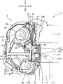
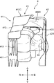
以下、図面に基づいて、本発明の実施形態に係るターボ過給機付エンジンを詳細に説明する。先ずは、当該エンジンの全体構成について説明する。図1は、本発明の実施形態に係るターボ過給機付エンジン1の斜視図、図2は、エンジン1の上面図、図3は、エンジン1から、排気ガス浄化装置と各種ヒートインシュレータとを取り外した状態の斜視図である。また、図4は、エンジン1の要部を一部破断して示す斜視図、図5は、図1のV−V線断面図である。なお、図5においては、エンジン本体10を簡略的に示している。これら図1〜図5、及び他の図面において、前後、左右、上下の方向表示を付している。これは説明の便宜のためであり、実際の方向を必ずしも示すものではない。
[Entire engine configuration]
Hereinafter, an engine with a turbocharger according to an embodiment of the present invention will be described in detail based on the drawings. First, the overall configuration of the engine will be described. 1 is a perspective view of an
ターボ過給機付エンジン1は、多気筒型のエンジン本体10と、エンジン本体10の左側面に連結されたエキゾーストマニホールド2と、エンジン本体10の左方に配置されたターボ過給機3と、エキゾーストマニホールド2の周囲を覆うマニホールドインシュレータ4とを含む。
The
エンジン本体10は、直列四気筒のエンジンであり、シリンダブロック11と、シリンダブロック11の上面に取り付けられたシリンダヘッド12と、シリンダヘッド12の上方に配置されたシリンダヘッドカバー13とを備えている。シリンダブロック11は、気筒毎の燃焼室を形成する4つのシリンダボア111(図5にその一つが示されている)を備えている。シリンダボア111の配列方向は、前後方向である。すなわち、本実施形態において気筒配列方向は、前後方向となる。
The
シリンダヘッド12は、各シリンダボア111の上端と吸気弁を介して連通する複数の吸気ポート(図示せず)と、排気弁を介して連通する複数の排気ポート121(図5)とを備える。前記吸気ポートの取り付け口にはインテークマニホールド(図には表れていない)が連結されている。一方、排気ポート121の取り付け口122にはエキゾーストマニホールド2が連結されている。シリンダヘッドカバー13は、樹脂製のカバーであり、シリンダヘッド12が備える動弁機構を覆うよう、シリンダヘッド12の上面に取り付けられている。
The
エンジン本体10の左側面であってターボ過給機3(タービンケース)に対向する位置には、エンジン本体インシュレータ14が配置されている。エンジン本体インシュレータ14は、アルミメッキ鋼鈑若しくは該鋼鈑を含む合板の絞り加工品等からなる遮熱板である(以下で説明する他のインシュレータも同じ)。エンジン本体インシュレータ14は、シリンダヘッドカバー13の左側方に隣接し、上下方向に延びる概ね平板状のインシュレータである。エンジン本体インシュレータ14は、専らエンジン本体10から排出される高温の排気ガスが流通するエキゾーストマニホールド2及びターボ過給機3から発せられる熱から、シリンダヘッドカバー13、ハーネス、センサ類を保護する。
An
エキゾーストマニホールド2は、各気筒の排気ポート121から排出される排気ガスを一つの流路に集合させる排気通路20(図5)を内部に備えている。上述の通り、エキゾーストマニホールド2の入気側はシリンダヘッド12に連結され、出気側はターボ過給機3に接続されている。本実施形態では、エキゾーストマニホールド2は、気筒配列方向である前後方向が長手方向となる部材である。
The
マニホールドインシュレータ4は、エキゾーストマニホールド2から発せられる熱によって周辺部品が熱害を受けないよう遮熱するインシュレータである。本実施形態ではマニホールドインシュレータ4は、エキゾーストマニホールド2の左右側面と、上面とを覆っている。また、マニホールドインシュレータ4は、当該インシュレータ4内の熱気を積極的に外部へ逃がすための第1開口部G1及び第2開口部G2を備えている。これら、エキゾーストマニホールド2及びマニホールドインシュレータ4については、図6以下を参照して後記で詳述する。
The
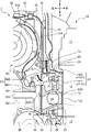
ターボ過給機3は、エンジン本体10から排出される排気エネルギーを利用して、エンジン本体10の吸気を過給する装置である。ターボ過給機3は、低速域乃至は中速域から高速域において作動して吸気を過給する大型ターボ3Aと、低速域のみで作動して吸気を過給する小型ターボ3Bとを備えている。本実施形態では、大型ターボ3Aの下方に小型ターボ3Bが連設されている。大型ターボ3A及び小型ターボ3Bは各々、前方側に配置されるタービン室と、後方側に配置されるコンプレッサ室とを備える。タービン室にはタービン翼車が、コンプレッサ室にはブロワー扇車がそれぞれ配置されている。タービン翼車とブロワー扇車とは軸部材で連結され、両者は軸回りに一体回転する。
The
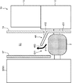
図5には、大型ターボ3Aの大タービン室31A及び小型ターボ3Bの小タービン室31Bが示されている。大タービン室31Aは、エキゾーストマニホールド2よりも上方に配置されたタービン室である。一方、小タービン室31Bは、エキゾーストマニホールド2よりもやや下方に配置されている。これら大タービン室31A及び小タービン室31Bには、エキゾーストマニホールド2から排気ガスが供給される。
FIG. 5 shows a
ターボ過給機3は、大タービン室31A及び小タービン室31と、排気ガスの通路となるガス通路とを区画するタービンハウジング32を備えている。タービンハウジング32は、タービンヘッド321、大型ターボハウジング33及び小型ターボハウジング34を含む。タービンヘッド321は、エキゾーストマニホールド2から供給される排気ガスを、大タービン室31A及び小タービン室31Bに導くガス通路を内部に有している。
The
大型ターボハウジング33は、大タービン室31Aの空間を区画する部材である。大型ターボハウジング33の下端には、フランジ形状を有するハウジングベース331が取り付けられている。小型ターボハウジング34は、小タービン室31Bの空間を区画する部材であり、タービンヘッド321と一体的に成形されている。タービンヘッド321の上端には、支持フランジ322が設けられている。支持フランジ322の上にハウジングベース331が載置され、両者がボルト締結されている。
The
タービンハウジング32の周囲は、タービンインシュレータ37によって覆われている。本実施形態においては、タービン室の周囲を覆うタービンケースとして、タービンハウジング32とタービンインシュレータ37とを含む。大型ターボ3Aが配置されたターボ過給機3の上方部分では、大型ターボハウジング33がタービンスクロール部の空間及びタービン翼車を収容する空間を区画し、タービンインシュレータ37は、大型ターボハウジング33の外周面に対して空間を置いて、当該大型ターボハウジング33の周囲を覆っている。タービンインシュレータ37は、エンジン本体10(シリンダヘッドカバー13)と対向する側に、上下方向に平板状に延びる対向壁部37Aを有する。対向壁部37Aの下端は、マニホールドインシュレータ4の上面近傍まで延びている。
The periphery of the
タービンインシュレータ37とシリンダヘッドカバー13とは、空間を介して左右方向(横方向)に略同じ高さ位置で隣接している。シリンダヘッドカバー13の、タービンインシュレータ37の対向壁部37Aと対向する側面には、エンジン本体インシュレータ14が配置されている。このため、共に平板状の対向壁部37Aとエンジン本体インシュレータ14とが、空間を挟んで左右方向において対向している。この空間は、エキゾーストマニホールド2の上方において上下方向(前後方向)に延びる帯状空間であり、本実施形態では該空間をマニホールド上方空間S1という。
The
大型ターボハウジング33は、略円筒型の大タービン室31Aの形状に沿って円筒型の外形形状を有している。一方、対向壁部37Aは平板状の部材である。対向壁部37Aは、大型ターボハウジング33の最も右方に突出した部分に対して、左右方向に所定間隔を有するように配置されている。大型ターボハウジング33とタービンインシュレータ37(対向壁部37A)との間の空間を、本実施形態では過給機内空間S2という。
The
ターボ過給機3は、タービン側フランジ部35及び排気装置側フランジ36(図4)を備えている。タービン側フランジ部35は、タービンヘッド321の入気側に設けられ、エキゾーストマニホールド2の出気側に接続されるフランジ部である。マニホールド上方空間S1は、タービン側フランジ部35の配置位置を前後方向の略中心として、上方に延びている。排気装置側フランジ36は、排気経路の下流側配管に接続されるフランジ部である。
The
排気経路の下流側配管には、排気ガス浄化装置が取り付けられている。排気ガス浄化装置は、排気ガス中に含まれる有害物質を除去する触媒装置である。排気ガス浄化装置の配置位置は、エンジン本体10の左側方であって、ターボ過給機3の前方である。図1及び図2では、遮熱のために前記排気ガス浄化装置の上面を覆うCATA上インシュレータ51と、側面を覆うCATA横インシュレータ52とを示している。
An exhaust gas purification device is attached to the downstream pipe of the exhaust path. The exhaust gas purification device is a catalyst device that removes harmful substances contained in the exhaust gas. The arrangement position of the exhaust gas purification device is on the left side of the
CATA上インシュレータ51の後端部分がタービンインシュレータ37の前端部分の上方に重なるように、両者が組み付けられている。但し、両インシュレータ37、51は、タービンハウジング32及び排気ガス浄化装置の組立体の上面を完全に覆ってはおらず、エンジン本体10寄りの位置には上面開口53が設けられている。
Both are assembled so that the rear end portion of the CATA
[熱気逃がし構造の詳細]
上述の通り、マニホールドインシュレータ4は、周辺部品への熱害防止のためにエキゾーストマニホールド2の周囲を覆っている。しかし、エキゾーストマニホールド2を覆ったとしても、マニホールドインシュレータ4内に熱気を完全に閉じ込めることはできず、予期せぬ隙間から前記熱気が漏れ出し、周辺部品に熱害を与えることが想定される。そこで、本実施形態のマニホールドインシュレータ4は、熱気逃がし用の開口として、第1開口部G1及び第2開口部G2を備えている。第1開口部G1は、マニホールド上方空間S1に向けて開口し、第2開口部G2は過給機内空間S2に向けて開口しており、これら空間S1、S2へマニホールドインシュレータ4内の熱気を積極的に逃がす構造が備えられている。以下、当該熱気逃がし構造について、図6〜図11を参照して詳述する。
[Details of hot air escape structure]
As described above, the
図6は、図5の要部拡大断面図である。図7は、マニホールドインシュレータ4が付設されたエキゾーストマニホールド2の斜視図である。本実施形態では、マニホールドインシュレータ4が、2つの分割片の組合せによって構成される例を示す。マニホールドインシュレータ4は、エンジン本体10側に配置される第1インシュレータ片41と、ターボ過給機3側に配置される第2インシュレータ片42との組合せからなる。
6 is an enlarged cross-sectional view of a main part of FIG. FIG. 7 is a perspective view of the
図8は、第2インシュレータ片42が取り外された状態のエキゾーストマニホールド2の斜視図、図9は、第1インシュレータ片41が取り外された状態のエキゾーストマニホールド2の斜視図である。図10は、第1インシュレータ片41と第2インシュレータ片42との組合体(マニホールドインシュレータ4)の斜視図、図11は、図10に示した組立体の側面図である。
FIG. 8 is a perspective view of the
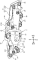
<エキゾーストマニホールド>
エキゾーストマニホールド2は、マニホールド型の排気通路20が形成された本体部のエンジン本体10側に入気側フランジ部21を(図9参照)、ターボ過給機3側に出気側フランジ部22を(図8参照)、それぞれ備えている。入気側フランジ部21はシリンダヘッド12に接続され、出気側フランジ部22はタービンヘッド321に接続される。このエキゾーストマニホールド2により、排気ポート121から排出される排気ガスが、ターボ過給機3の大タービン室31A及び小タービン室31Bに導かれる。
<Exhaust manifold>
The
入気側フランジ部21には、排気通路20のマニホールド開口端となる4つの入気開口231、232、233、234が、前後方向に並んで設けられている。このため入気側フランジ部21は、前後方向に長尺の形状を有している。これら入気開口231〜234は、各気筒の排気ポート121の取り付け口122に対応して配列されている。入気側フランジ部21の外周縁には、複数の膨出部211が突設されている。これら膨出部211には、それぞれ貫通孔212が穿孔されている。なお、入気側フランジ部21の前後方向中央付近に配置されている2つの膨出部211は、とりわけ上方へ大きく突出しており、これによりエキゾーストマニホールド2の上面の高さが前記中央付近において他の部分よりも高い高上面部25となっている。
The inlet
出気側フランジ部22には、ターボ過給機3に対する排気経路の連通開口となる1つの出気開口24が設けられている。出気側フランジ部22は、左方からの側面視で略直角三角形の形状を有しており、その上面には前端から後端に向けて下る斜辺部221が備えられている。前記直角三角形の3つの角部付近には、それぞれフランジスタッド222が左方に向けて突設されている。なお、上述の高上面部25と出気側フランジ部22とは、左右方向において対峙する位置関係にある。つまり、高上面部25は、ターボ過給機3に対する接続部位の近傍に位置している。
The outlet
入気側フランジ部21は、各排気ポート121の取り付け口122と入気開口231〜234とが位置合わせされた状態で、シリンダヘッド12に突き合わせ接続される。この接続の際、締結ボルト26が、それぞれ貫通孔212を通してシリンダヘッド12のネジ孔に螺合されることにより、エキゾーストマニホールド2がシリンダヘッド12に締結固定される。
The inlet
入気側フランジ部21の端面(右面)とシリンダヘッド12における取り付け口122の配列面との間には、入気側ガスケット21Gが介在される。入気側ガスケット21Gは、積層型のメタルガスケットであり、当該接続部において排気ガスのシールを行う。図9には、入気側ガスケット21Gの右面が表出している。
An
なお、本実施形態では、マニホールドインシュレータ4の第1インシュレータ片41が、入気側ガスケット21Gと一体化されている例を示している。第1インシュレータ片41は、積層型メタルガスケットからなる入気側ガスケット21Gの、最も右側の層(勿論、最も右側でなくとも良い)を構成しており、図9は入気側ガスケット21Gの第1インシュレータ片41が取り除かれた面が露呈している状態を示している。
In the present embodiment, an example in which the
出気側フランジ部22は、タービンヘッド321の入口側に設けられているタービン側フランジ部35と突き合わせ接続される。この接続の際、フランジスタッド222がタービン側フランジ部35に穿孔されている貫通孔を貫通し、ボルト締めによって両フランジ部22、35が固定される(図4参照)。出気側フランジ部22の接合面22S(左面)とタービン側フランジ部35との間には、出気側ガスケット22Gが介在される。この出気側ガスケット22Gも、積層型メタルガスケットである。なお、第2インシュレータ片42は、両フランジ部22、35には挟み込まれておらず、出気側フランジ部22の接合面22Sは露呈している(図7参照)。
The outlet
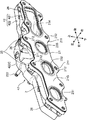
<マニホールドインシュレータ>
マニホールドインシュレータ4は、エキゾーストマニホールド2の形状に合わせて、前後方向に長い形状を有している。また、エキゾーストマニホールド2が前後方向中央付近に高上面部25を有していることから、マニホールドインシュレータ4もまた、その前後方向中央付近に、高上面部25を覆うように上方へ突出した凸状部43を有している。なお、本実施形態では、マニホールドインシュレータ4の底面にはインシュレータ機能を果たす壁部が存在しない例を示しているが、前記底面にも壁部を設けるようにしても良い。
<Manifold insulator>
The
既述の通り、マニホールドインシュレータ4は、第1インシュレータ片41と第2インシュレータ片42との組合体からなる。エンジン本体10側に配置される第1インシュレータ片41は、第1立ち壁部411(立ち壁部)と第1上壁部412(上壁部)とを含み、前記気筒配列方向に直交する断面(図5及び図6)において、逆L字型の形状を備えている。第1立ち壁部411は、エンジン本体10(シリンダヘッド12)の左側面に沿って上下方向に延びる壁部である。第1上壁部412は、第1立ち壁部411の上端からエキゾーストマニホールド2の上方に向けて左横方向に延出する壁部である。
As described above, the
ターボ過給機3側に配置される第2インシュレータ片42は、第2立ち壁部421と第2上壁部422とを含み、第1インシュレータ片41と同様に、気筒配列方向に直交する断面において、逆L字型の形状を備えている。第2立ち壁部421は、ターボ過給機3の側面に沿って上下方向に延びる壁部である。第2上壁部422は、第2立ち壁部421の上端からエキゾーストマニホールド2の上方に向けて右横方向に延出する壁部である。
The
第1インシュレータ片41と第2インシュレータ片42とは、第1立ち壁部411と第2立ち壁部421とが互いに対向し、第1上壁部412と第2上壁部422とが上下方向において一部が重なり合うように組み合わされている。本実施形態では、第1上壁部412の一部が第2上壁部422の上方に覆い被さる態様で、両者が組み合わされている。
As for the
第1インシュレータ片41の第1立ち壁部411には、複数の窓部413及び複数のボルト孔414が穿孔されている。窓部413は、排気ガスの通過口となる開口であり、エキゾーストマニホールド2の入気開口231〜234に位置合わせされた開口である。ボルト孔414は、締結ボルト26が挿通される貫通孔212に位置合わせされた孔である。第1立ち壁部411(第1インシュレータ片41)は、締結ボルト26によって、シリンダヘッド12に締結固定される。
A plurality of
なお、第1立ち壁部411は、入気側ガスケット21Gの最も右側の層を構成する部材でもあり、図9に示す入気側ガスケット21Gの右面に取り付けられる。換言すると、第1インシュレータ片41は、入気側ガスケット21Gの積層金属板のうちの一つの金属板の上端に、横方向に延び出す延長部(上壁部)を連設した部材である。従って、第1インシュレータ片41は、入気側ガスケット21Gと一体となって、入気側フランジ部21とシリンダヘッド12の排気ポート121のフランジ部との間に挟まれた状態で、シリンダヘッド12に締結固定される。
In addition, the 1st standing
第2インシュレータ片42の第2立ち壁部421には、複数のボルト挿通孔423が穿孔されている(図10)。ボルト挿通孔423は、エキゾーストマニホールド2の左面側に設けられた、ネジ孔を有するボス部に対応して穿孔されている。第2立ち壁部421(第2インシュレータ片42)は、ボルト挿通孔423を通して前記ボス部に螺合される締結ボルト27によって、エキゾーストマニホールド2に締結固定されている。なお、締結ボルト27による固定部は、第2インシュレータ片42の振動抑制のためにフローティング構造を採用することが望ましい。
A plurality of bolt insertion holes 423 are drilled in the second
第1インシュレータ片41と第2インシュレータ片42とを組み合わせるに際し、両者が接触する状態とすると、車両運転時の振動によって異音が発生し得る。このため、上下方向に重なり合う第1上壁部412と第2上壁部422との間には、所定間隔の間隙Gが確保されている(図10参照)。本実施形態では、前記間隙Gが、マニホールドインシュレータ4の前後方向中央付近に存在する凸状部43の位置において、他の位置よりも広くされている。この間隙Gが広くされた部分が、マニホールドインシュレータ4内の熱気を逃がす第1開口部G1である。
When the
詳しくは、第1上壁部412は、前後方向中央付近において上方に膨出した中央部分412Cを有し、同様に第2上壁部422も上方に膨出した中央部分422Cを有する。これら中央部分412C、422Cが重なり合う部分において、両者間の間隙Gが他の部分の間隙Gよりも相対的に広くされることによって、熱気を積極的に逃がすことが可能な第1開口部G1が形成されている。第1開口部G1は、エキゾーストマニホールド2とターボ過給機3との接続部位となる出気側フランジ部22の上方に位置している。
Specifically, the first
図6を参照して、第1立ち壁部411は、エンジン本体インシュレータ14の下方に連なるように配置されている。本実施形態では、エンジン本体インシュレータ14の下端からやや右方にシフトした位置から、第1立ち壁部411は下方に延びている。第1上壁部412は、第1立ち壁部411に連なる基端部T1と、延出方向の先端(左端)である端縁部T2とを備えている。端縁部T2は、第1開口部G1の一部を区画している。第1上壁部412が延出する方向は、タービンケース(タービンインシュレータ37)に向かう方向である。第1上壁部412は、端縁部T2が基端部T1よりも高くなるよう、上方に傾斜している、これにより、第1上壁部412と第2上壁部422との間隔が拡げられている。第1開口部G1は、タービンインシュレータ37とエンジン本体インシュレータ14との間の空間を指向するように、つまり、マニホールド上方空間S1に向けて開口している。
Referring to FIG. 6, the first standing
図7に示すように、第2開口部G2は、第2インシュレータ片42の第2立ち壁部421に設けられている。第2立ち壁部421には、出気側フランジ部22の接合面22Sを露出させる切り欠き部44が設けられている。切り欠き部44は、左面視で直角三角形の形状を有する出気側フランジ部22の前側辺223と対向する垂直縁441と、上側の斜辺部221と対向する傾斜縁442とを備える。なお、ここで例示している切り欠き部44は、出気側フランジ部22の底辺と対向する縁部を持たない解放型の切り欠きであるが、前記底辺を対向する縁部を具備する窓型の切り欠きとしても良い。
As shown in FIG. 7, the second opening G <b> 2 is provided in the
切り欠き部44は、本来的には出気側フランジ部22の接合面22Sを露出させ、タービン側フランジ部35との接合を実現させる役目を果たす。このため、切り欠き部44の切り欠き縁と出気側フランジ部22の外周縁との間隔、具体的には前側辺223と垂直縁441との間隔並びに斜辺部221と傾斜縁442との間隔は、走行振動の発生時に接触が生じない程度の間隔が設定されていれば良い。しかし、本実施形態では、斜辺部221と傾斜縁442との間隔が、他の位置の間隔(前側辺223と垂直縁441との間隔)よりも相対的に広くされている。すなわち、傾斜縁442の大部分が、斜辺部221から離間するように上方へ凸状に窪んでいる。これにより、出気側フランジ部22の上方であって斜辺部221と傾斜縁442との間には、当該斜辺部221に沿った開口部が形成されている。かかる開口部が、第2開口部G2である。
The
図6に示されているように、第2開口部G2は、タービンハウジング32(大型ターボハウジング33)とタービンインシュレータ37との間の過給機内空間S2に向けて開口している。切り欠き部44は、タービンインシュレータ37の対向壁部37Aよりも左方に位置している。つまり、対向壁部37Aが第2立ち壁部421の上方に位置するよう両者が上下方向に並び、且つ、第2立ち壁部421が対向壁部37Aよりもタービンハウジング32に接近する側に配置されている。このような第2立ち壁部421に、切り欠き部44が設けられている。
As shown in FIG. 6, the second opening G <b> 2 opens toward the supercharger internal space S <b> 2 between the turbine housing 32 (large turbo housing 33) and the
<熱気の流れ>
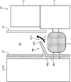
図6を参照して、エンジン本体10における高温燃焼で生じた排気ガスがエキゾーストマニホールド2を通過すると、当該エキゾーストマニホールド2の外周面から熱気が発生する。エキゾーストマニホールド2の上方は、第1インシュレータ片41と第2インシュレータ片42との組合体によって覆われているので、前記熱気は周辺に無秩序には放散されない。前記熱気は、エキゾーストマニホールド2内において対流によって上昇するが、エキゾーストマニホールド2の上部には第1開口部G1及び第2開口部G2が設けられているので、これら開口部から前記熱気は外部に逃げ出すことになる。
<Flow of hot air>
Referring to FIG. 6, when exhaust gas generated by high-temperature combustion in
第1開口部G1からは、熱気F1がマニホールド上方空間S1に向けて放出される。第1上壁部412の一部が第2上壁部422の上方に覆い被さっており、第1上壁部412は端縁部T2が上向きとなるよう傾斜している。このため、熱気F1は、タービンインシュレータ37の下端付近に向かい、その後、耐熱性に優れた空間であるマニホールド上方空間S1を上方に向かうことになる。つまり、第1上壁部412が樹脂製のシリンダヘッドカバー13に決して熱気F1が漏れ出すことがないよう熱気F1をガイドしていると言うことができる。なお、熱気F1は、マニホールド上方空間S1を抜けた後、ボンネットフード(図示せず)内において四散する。
Hot air F1 is discharged toward the manifold upper space S1 from the first opening G1. A part of the first
第2開口部G2からは、熱気F2が過給機内空間S2に向けて放出される。切り欠き部44は、タービンハウジング32と対峙する第2立ち壁部421に設けられている。このため、熱気F2はタービンハウジング32側に向けて放出され、その後、過給機内空間S2を上方に向かう。過給機内空間S2もまた、耐熱性に優れた空間であるので、熱気F2の流通によって熱害が発生しない。しかる後、熱気F2は、タービンインシュレータ37の上面に突き当たり、このタービンインシュレータ37とCATA上インシュレータ51との間の上面開口53(図2参照)から上方へ放散される。
Hot air F2 is discharged from the second opening G2 toward the supercharger internal space S2. The
[作用効果]
以上説明した本実施形態に係るターボ過給機付エンジン1によれば、次のような作用効果を奏する。エンジン1は、タービンインシュレータ37(タービンケース)とエンジン本体インシュレータ14との間であって、マニホールドインシュレータ4の上方にマニホールド上方空間S1を備える。そして、マニホールドインシュレータ4は、エキゾーストマニホールド2とターボ過給機3との接続部位(出気側フランジ部22とタービン側フランジ部35との接続部)の上方位置に、マニホールド上方空間S1に向けて開口する熱気逃がし用の第1開口部G1を備える。
[Function and effect]
The
従って、マニホールドインシュレータ4内で生じる熱気は、第1開口部G1を通して、マニホールドインシュレータ4の上方のマニホールド上方空間S1へ積極的に逃がされる。このマニホールド上方空間S1は、タービンインシュレータ37とエンジン本体インシュレータ14との間の空間であって、当該上方空間S1を区画する部材は本来的に優れた耐熱性を有する部材である。つまり、エンジン1では、前記熱気を耐熱性に優れる空間に誘導して該熱気を逃がす構造が実現される。このため、熱害発生の不具合、例えばマニホールドインシュレータ4と他の部材との隙間等から前記熱気がランダムに逃げ出して、周辺部品に熱害を与えるというような不具合、を防止することができる。
Accordingly, the hot air generated in the
さらに、マニホールドインシュレータ4は、過給機内空間S2に向けて開口する第2開口部G2を備える。過給機内空間S2もまた、タービンハウジング32とタービンインシュレータ37とによって区画された、耐熱性に優れる空間である。第1開口部G1に加え、上記のような第2開口部G2からも積極的に熱気を逃がすことで、周辺部品への熱害の発生を一層効果的に抑制することができる。
Furthermore, the
マニホールドインシュレータ4は、エキゾーストマニホールド2の高上面部25を覆う凸状部43を備え、第1開口部G1は、凸状部43に配置されている。このように、熱気逃がし用の第1開口部G1を、マニホールドインシュレータ4において高い位置に存在する凸状部43に配置することで、マニホールドインシュレータ4内の熱気を、自然対流の作用によってスムースに第1開口部G1から逃がすことができる。
The
マニホールドインシュレータ4の第1インシュレータ片41は、気筒配列方向に直交する断面において、上下方向に延びる第1立ち壁部411と横方向に延出する第1上壁部412とを備える逆L字型の形状を有する。そして、第1上壁部412は、端縁部T2が基端部T1よりも高くなるよう、上方に傾斜している。このため、第1上壁部412の上方傾斜に沿って、マニホールドインシュレータ4内の熱気が第1開口部G1に導かれる。すなわち、第1上壁部412によって、前記熱気を第1開口部G1へ向けて誘導し、該熱気を第1開口部G1から集中的に放出させることができる。
The
また、第1立ち壁部411は、エンジン本体インシュレータ14の下方に連なるように配置され、第1上壁部412が延出する方向は、タービンインシュレータ37に向かう方向である。このため、エンジン本体インシュレータ14が遮熱している対象物(シリンダヘッドカバー13、及びハーネス、センサ類等)から遠ざかる方向に、前記熱気を第1開口部G1から放出させることができる。従って、前記対象物に対する熱害を確実に抑制することができる。さらに、エンジン本体インシュレータ14がシリンダヘッドカバー13の側方に配置されていることから、シリンダヘッドカバー13として、耐熱グレードが低い部材、例えば樹脂にて形成された部材を用いることができる。
Further, the first standing
[変形実施形態の説明]
以上、本発明の一実施形態を説明したが、本発明はこれに限定されるものではなく、次のような変形実施形態を取ることができる。
[Description of Modified Embodiment]
As mentioned above, although one Embodiment of this invention was described, this invention is not limited to this, The following modified embodiment can be taken.
図12は、変形実施形態に係るマニホールドインシュレータ4Aを示す概略的な断面図である。上記実施形態では、マニホールドインシュレータ4が、第1、第2インシュレータ片41、42の組合せからなる態様を例示した。これに対し、図12では、エンジン本体10側に配置された一つのインシュレータ片からなるマニホールドインシュレータ4Aを例示している。
FIG. 12 is a schematic cross-sectional view showing a
マニホールドインシュレータ4Aは、エンジン本体インシュレータ14の下方に連なる立ち壁部451と、立ち壁部451の上端からターボ過給機3に向けて斜め上方向に延びる上壁部452とを含む。立ち壁部451は、エキゾーストマニホールド2の熱がエンジン本体10側に向かわないよう遮熱している。上壁部452は、エキゾーストマニホールド2の上面を概ね覆っている。上壁部452の端縁部453とタービンインシュレータ37との間には、開口部G11が形成されている。マニホールドインシュレータ4A内の熱気F11は、この開口部G11からマニホールド上方空間S1へ放出される。この変形実施形態によっても、熱気F11をシリンダヘッドカバー13から遠ざかる方向に放出させることができる。
The
図13は、他の変形実施形態に係るマニホールドインシュレータ4Bを示す概略的な断面図である。図13では、ターボ過給機3側に配置された一つのインシュレータ片からなるマニホールドインシュレータ4Bを例示している。マニホールドインシュレータ4Bは、タービンインシュレータ37の下方に連なる立ち壁部461と、立ち壁部461の上端からエンジン本体10に向けて斜め上方向に延びる上壁部462とを含む。立ち壁部461には、第2開口部G2に相当する開口部が設けられていても良い。
FIG. 13 is a schematic cross-sectional view showing a
上壁部462は、エキゾーストマニホールド2の上面を概ね覆っている。上壁部462の端縁部463とエンジン本体インシュレータ14との間には、開口部G12が形成されている。マニホールドインシュレータ4B内の熱気F12は、この開口部G12からマニホールド上方空間S1へ放出される。この変形実施形態では、熱気F12がエンジン本体10側に向かうことになるが、例えばエンジン本体インシュレータ14が十分にエンジン本体10の遮熱をしている場合、或いはシリンダヘッドカバー13が金属製の場合等には、当該変形実施形態を採用することができる。
The
図14は、さらに他の変形実施形態に係るマニホールドインシュレータ4Cを示す概略的な側面図(ターボ過給機3側から見た側面図)である。上記実施形態では、マニホールドインシュレータ4が凸状部43を有し、該凸状部43に第1開口部G1が形成される例を示した。図14では、上面に凸状部43のような隆起した部分が存在しないマニホールドインシュレータ4Cを例示している。
FIG. 14 is a schematic side view (a side view seen from the
マニホールドインシュレータ4Cは、第1インシュレータ片41Aと第2インシュレータ片42との組合せからなる。両インシュレータ片41A、42Aは、側面視で矩形形状を有し、両者間に僅かな隙間が存在する状態で組み合わされている。この隙間が、エキゾーストマニホールド2の出気側フランジ部22の配置位置で大きくなるよう、第2インシュレータ片42の上面には凹部424が設けられている。この凹部424の形成部分が、マニホールドインシュレータ4C内の熱気F13を外部に逃がす開口部G13とされている。
The
以上、各種の開口部G11、G12、G13を示した通り、エキゾーストマニホールド2とターボ過給機3との接続部位の上方位置であって、マニホールド上方空間S1に向けて開口する限りにおいて、熱気逃がし用の開口部は種々の態様を取ることができる。また、上記実施形態では、マニホールドインシュレータ4に第1開口部G1及び第2開口部G2を設ける例を示したが、第2開口部G2を省略するようにしても良い。例えば、マニホールド上方空間S1が比較的広く、マニホールドインシュレータ4内の熱気の逃がし経路として十分な容積を具備している場合は、第1開口部G1を比較的広くする一方で、第2開口部G2を実質的に設けない態様とすることができる。
As described above, as shown in the various openings G11, G12, and G13, as long as the
1 ターボ過給機付エンジン
10 エンジン本体
12 シリンダヘッド
13 シリンダヘッドカバー
14 エンジン本体インシュレータ
2 エキゾーストマニホールド
25 高上面部
3 ターボ過給機
3A 大型ターボ
3B 小型ターボ
31A 大タービン室(タービン室)
31B 小タービン室
32 タービンハウジング(タービンケース)
37 タービンインシュレータ(タービンケース)
4 マニホールドインシュレータ
41 第1インシュレータ片
411 第1立ち壁部(立ち壁部)
412 第1上壁部(上壁部)
S1 マニホールド上方空間
G1 第1開口部(開口部)
G2 第2開口部
T1 基端部
T2 端縁部
DESCRIPTION OF
31B
37 Turbine insulator (turbine case)
4
412 First upper wall (upper wall)
S1 Manifold upper space G1 First opening (opening)
G2 Second opening T1 Base end T2 End edge
Claims (6)
前記エンジン本体に連結されるエキゾーストマニホールドと、
前記エキゾーストマニホールドから排気が供給されるタービン室を備え、該タービン室が前記エキゾーストマニホールドよりも上方に配置されたターボ過給機と、
前記エキゾーストマニホールドの周囲を覆うマニホールドインシュレータと、を備え、
前記ターボ過給機は、前記タービン室の周囲を覆うタービンケースを有し、
前記エンジン本体の前記タービンケースと対向する位置にエンジン本体インシュレータが配置され、
前記タービンケースとエンジン本体インシュレータとの間であって、前記マニホールドインシュレータの上方にはマニホールド上方空間が設けられ、
前記マニホールドインシュレータは、前記エキゾーストマニホールドと前記ターボ過給機との接続部位の上方位置に、前記マニホールド上方空間に向けて開口する熱気逃がし用の開口部を備えることを特徴とするターボ過給機付エンジン。 A multi-cylinder engine body,
An exhaust manifold coupled to the engine body;
A turbocharger comprising a turbine chamber to which exhaust gas is supplied from the exhaust manifold, the turbine chamber being disposed above the exhaust manifold;
A manifold insulator covering the periphery of the exhaust manifold,
The turbocharger has a turbine case that covers the periphery of the turbine chamber,
An engine body insulator is disposed at a position facing the turbine case of the engine body,
Between the turbine case and the engine body insulator, a manifold upper space is provided above the manifold insulator,
The manifold insulator includes a turbocharger opening provided at a position above a connection portion between the exhaust manifold and the turbocharger, and opens to a space above the manifold. engine.
前記エキゾーストマニホールドは、前記ターボ過給機との接続部位の近傍に、前記多気筒の気筒配列方向において上面の高さが他の部分よりも高い高上面部を備え、
前記マニホールドインシュレータは、前記高上面部を覆う凸状部を備え、
前記開口部は、前記凸状部に配置されている、ターボ過給機付エンジン。 In the turbocharged engine according to claim 1,
The exhaust manifold is provided with a high upper surface portion in the vicinity of a connection portion with the turbocharger, the height of the upper surface being higher than other portions in the cylinder arrangement direction of the multi-cylinder
The manifold insulator includes a convex portion that covers the high upper surface portion,
The said opening part is an engine with a turbocharger arrange | positioned at the said convex-shaped part.
前記マニホールドインシュレータは、前記気筒配列方向に直交する断面において、上下方向に延びる立ち壁部と横方向に延出する上壁部とを備える逆L字型の形状を備え、
前記上壁部は、前記立ち壁部に連なる基端部と、延出方向の先端である端縁部とを備え、前記端縁部は、前記開口部の一部を区画するものであり、
前記上壁部は、前記端縁部が前記基端部よりも高くなるよう、上方に傾斜している、ターボ過給機付エンジン。 The turbocharged engine according to claim 2,
The manifold insulator has an inverted L-shaped shape including a standing wall portion extending in the vertical direction and an upper wall portion extending in the horizontal direction in a cross section perpendicular to the cylinder arrangement direction.
The upper wall portion includes a base end portion connected to the standing wall portion and an end edge portion which is a distal end in the extending direction, and the end edge portion defines a part of the opening.
The turbocharged engine, wherein the upper wall portion is inclined upward such that the end edge portion is higher than the base end portion.
前記立ち壁部は、前記エンジン本体インシュレータの下方に連なるように配置され、
前記上壁部が延出する方向は、前記タービンケースに向かう方向である、ターボ過給機付エンジン。 In the turbocharged engine according to claim 3,
The standing wall portion is arranged so as to be continuous below the engine body insulator,
The turbocharged engine is a direction in which the upper wall portion extends toward the turbine case.
前記エンジン本体は、排気ポートが形成されたシリンダヘッドと、該シリンダヘッドの上方に配置されたシリンダヘッドカバーとを備え、
前記エンジン本体インシュレータは、前記シリンダヘッドカバーの側方に配置されている、ターボ過給機付エンジン。 The turbocharged engine according to any one of claims 1 to 4,
The engine body includes a cylinder head formed with an exhaust port, and a cylinder head cover disposed above the cylinder head,
The engine body insulator is an engine with a turbocharger, which is disposed on a side of the cylinder head cover.
前記タービンケースは、前記タービン室及びガス通路を区画するタービンハウジングと、該タービンハウジングを覆うタービンインシュレータとを含み、
前記マニホールド上方空間は、前記エンジン本体インシュレータと前記タービンインシュレータとの間の空間である、ターボ過給機付エンジン。 In the turbocharged engine according to any one of claims 1 to 5,
The turbine case includes a turbine housing that partitions the turbine chamber and a gas passage, and a turbine insulator that covers the turbine housing,
The turbo-supercharged engine, wherein the manifold upper space is a space between the engine body insulator and the turbine insulator.
Priority Applications (1)
| Application Number | Priority Date | Filing Date | Title |
|---|---|---|---|
| JP2016049904A JP6327270B2 (en) | 2016-03-14 | 2016-03-14 | Turbocharged engine |
Applications Claiming Priority (1)
| Application Number | Priority Date | Filing Date | Title |
|---|---|---|---|
| JP2016049904A JP6327270B2 (en) | 2016-03-14 | 2016-03-14 | Turbocharged engine |
Publications (2)
| Publication Number | Publication Date |
|---|---|
| JP2017166341A true JP2017166341A (en) | 2017-09-21 |
| JP6327270B2 JP6327270B2 (en) | 2018-05-23 |
Family
ID=59910120
Family Applications (1)
| Application Number | Title | Priority Date | Filing Date |
|---|---|---|---|
| JP2016049904A Active JP6327270B2 (en) | 2016-03-14 | 2016-03-14 | Turbocharged engine |
Country Status (1)
| Country | Link |
|---|---|
| JP (1) | JP6327270B2 (en) |
Cited By (1)
| Publication number | Priority date | Publication date | Assignee | Title |
|---|---|---|---|---|
| JP2020118082A (en) * | 2019-01-23 | 2020-08-06 | スズキ株式会社 | Vehicular internal combustion engine |
Citations (4)
| Publication number | Priority date | Publication date | Assignee | Title |
|---|---|---|---|---|
| JPS6276249U (en) * | 1985-10-30 | 1987-05-15 | ||
| JP2005201093A (en) * | 2004-01-14 | 2005-07-28 | Mazda Motor Corp | Cooling device of vehicle engine |
| JP2013050068A (en) * | 2011-08-31 | 2013-03-14 | Hino Motors Ltd | Heat insulator |
| JP2014088822A (en) * | 2012-10-30 | 2014-05-15 | Toyota Motor Corp | Engine heat shield structure |
-
2016
- 2016-03-14 JP JP2016049904A patent/JP6327270B2/en active Active
Patent Citations (4)
| Publication number | Priority date | Publication date | Assignee | Title |
|---|---|---|---|---|
| JPS6276249U (en) * | 1985-10-30 | 1987-05-15 | ||
| JP2005201093A (en) * | 2004-01-14 | 2005-07-28 | Mazda Motor Corp | Cooling device of vehicle engine |
| JP2013050068A (en) * | 2011-08-31 | 2013-03-14 | Hino Motors Ltd | Heat insulator |
| JP2014088822A (en) * | 2012-10-30 | 2014-05-15 | Toyota Motor Corp | Engine heat shield structure |
Cited By (2)
| Publication number | Priority date | Publication date | Assignee | Title |
|---|---|---|---|---|
| JP2020118082A (en) * | 2019-01-23 | 2020-08-06 | スズキ株式会社 | Vehicular internal combustion engine |
| JP7234649B2 (en) | 2019-01-23 | 2023-03-08 | スズキ株式会社 | internal combustion engine for vehicle |
Also Published As
| Publication number | Publication date |
|---|---|
| JP6327270B2 (en) | 2018-05-23 |
Similar Documents
| Publication | Publication Date | Title |
|---|---|---|
| WO2017159357A1 (en) | Engine equipped with turbo supercharger | |
| JP5581196B2 (en) | Engine cooling system | |
| US20100147257A1 (en) | Outboard motor | |
| JP6107863B2 (en) | Engine heat damage countermeasure structure | |
| JP2005201093A (en) | Cooling device of vehicle engine | |
| JP6550968B2 (en) | Engine intake supply structure | |
| JP6327270B2 (en) | Turbocharged engine | |
| CA2686580C (en) | Outboard motor | |
| JP6344416B2 (en) | Turbocharged engine | |
| JP5799719B2 (en) | Heat shield structure of gas flow path joint | |
| CN108506139B (en) | Internal combustion engine for vehicle | |
| JP2017014953A (en) | Intake manifold | |
| CA2686819C (en) | Outboard motor | |
| JP2014129801A (en) | Exhaust gas reflux device of vehicle engine | |
| JP7024639B2 (en) | Exhaust structure of internal combustion engine | |
| EP3112655B1 (en) | Intake manifold | |
| JP5550884B2 (en) | Exhaust gas recirculation device in internal combustion engine | |
| JP6645154B2 (en) | Intake manifold | |
| JP2015000676A (en) | Intake structure of outboard engine | |
| JP2018105182A (en) | Vehicle exhaust system structure | |
| EP3832121B1 (en) | Engine air intake device | |
| JP7206945B2 (en) | internal combustion engine for vehicle | |
| CN101598065A (en) | V-type engine | |
| JP2020196371A (en) | Vehicle front part structure | |
| JP6052108B2 (en) | Vehicle engine room structure |
Legal Events
| Date | Code | Title | Description |
|---|---|---|---|
| A977 | Report on retrieval |
Free format text: JAPANESE INTERMEDIATE CODE: A971007 Effective date: 20171227 |
|
| A131 | Notification of reasons for refusal |
Free format text: JAPANESE INTERMEDIATE CODE: A131 Effective date: 20180109 |
|
| A521 | Request for written amendment filed |
Free format text: JAPANESE INTERMEDIATE CODE: A523 Effective date: 20180305 |
|
| TRDD | Decision of grant or rejection written | ||
| A01 | Written decision to grant a patent or to grant a registration (utility model) |
Free format text: JAPANESE INTERMEDIATE CODE: A01 Effective date: 20180320 |
|
| A61 | First payment of annual fees (during grant procedure) |
Free format text: JAPANESE INTERMEDIATE CODE: A61 Effective date: 20180402 |
|
| R150 | Certificate of patent or registration of utility model |
Ref document number: 6327270 Country of ref document: JP Free format text: JAPANESE INTERMEDIATE CODE: R150 |