JP2017166325A - Wind power generation method in multistage vertical wind turbine - Google Patents
Wind power generation method in multistage vertical wind turbine Download PDFInfo
- Publication number
- JP2017166325A JP2017166325A JP2016049107A JP2016049107A JP2017166325A JP 2017166325 A JP2017166325 A JP 2017166325A JP 2016049107 A JP2016049107 A JP 2016049107A JP 2016049107 A JP2016049107 A JP 2016049107A JP 2017166325 A JP2017166325 A JP 2017166325A
- Authority
- JP
- Japan
- Prior art keywords
- rotor
- rotors
- speed
- clutch
- main shaft
- Prior art date
- Legal status (The legal status is an assumption and is not a legal conclusion. Google has not performed a legal analysis and makes no representation as to the accuracy of the status listed.)
- Granted
Links
Images


Classifications
-
- Y—GENERAL TAGGING OF NEW TECHNOLOGICAL DEVELOPMENTS; GENERAL TAGGING OF CROSS-SECTIONAL TECHNOLOGIES SPANNING OVER SEVERAL SECTIONS OF THE IPC; TECHNICAL SUBJECTS COVERED BY FORMER USPC CROSS-REFERENCE ART COLLECTIONS [XRACs] AND DIGESTS
- Y02—TECHNOLOGIES OR APPLICATIONS FOR MITIGATION OR ADAPTATION AGAINST CLIMATE CHANGE
- Y02E—REDUCTION OF GREENHOUSE GAS [GHG] EMISSIONS, RELATED TO ENERGY GENERATION, TRANSMISSION OR DISTRIBUTION
- Y02E10/00—Energy generation through renewable energy sources
- Y02E10/70—Wind energy
- Y02E10/74—Wind turbines with rotation axis perpendicular to the wind direction
Landscapes
- Wind Motors (AREA)
- Control Of Eletrric Generators (AREA)
Abstract
【課題】低風速下においても、ロータが失速するのを未然に防止しながら、効率よく発電しうる風力発電方法を提供する。【解決手段】発電機4に連係された縦主軸14に、複数のブレード7を有する上下複数段のロータのうち、下段の第1ロータ2Aを常時連結し、かつ上段の第2ロータ2Bをクラッチ15を介して連結し、第1、第2ロータが予め定めた平均風速以下で回転している場合に、クラッチ15を切断して第2ロータを空転させ、このロータが加速して回転する特定の周速に達したとき、クラッチを接続して空転させた第2ロータにより第1ロータを増速させながら、全てのロータの回転により発電することを繰返させる。【選択図】 図1PROBLEM TO BE SOLVED: To provide a wind power generation method capable of efficiently generating power while preventing a rotor from stalling even under a low wind speed. SOLUTION: Of a vertical rotor having a plurality of blades 7, a lower first rotor 2A is constantly connected to a vertical main shaft 14 linked to a generator 4, and an upper second rotor 2B is a clutch. When the first and second rotors are connected via 15, and the first and second rotors rotate at a predetermined average wind speed or less, the clutch 15 is disengaged to idle the second rotor, and the rotor is accelerated to rotate. When the peripheral speed is reached, the second rotor, which is idled by connecting the clutch, accelerates the first rotor, and all the rotors rotate to generate electric power. [Selection diagram]
Description
本発明は、縦主軸に上下複数段のロータを設けた多段縦軸風車における風力発電方法に関する。 The present invention relates to a wind power generation method in a multi-stage vertical axis wind turbine in which a vertical main shaft is provided with a plurality of upper and lower rotors.
複数の縦長の揚力型ブレードを有するロータを備える一般的な縦軸風車は、発電機のコギングトルクや発電負荷の影響により、低風速下ではロータが効率よく回転せず、発電効率は低い。
この問題を解決するために、本願の発明者は、揚力型ブレードの上下の端部に、縦主軸方向へ向かって傾斜する傾斜部を形成し、ブレードの内側面に沿って上下方向に拡散する気流を、傾斜部で受止めて回転力を高めるとともに、揚力(推力)を増大させ、ロータが効率よく回転しうるようにした縦軸風車を開発している(例えば特許文献1参照)。
A general vertical wind turbine including a rotor having a plurality of vertically long lift-type blades has low power generation efficiency because the rotor does not rotate efficiently under a low wind speed due to the cogging torque and power generation load of the generator.
In order to solve this problem, the inventor of the present application forms an inclined portion that is inclined toward the longitudinal main axis direction at the upper and lower ends of the lift type blade, and diffuses in the vertical direction along the inner surface of the blade. A vertical axis wind turbine has been developed in which an airflow is received by an inclined portion to increase rotational force and increase lift (thrust) so that the rotor can rotate efficiently (see, for example, Patent Document 1).
上記特許文献1に記載の縦軸風車は、ロータの回転効率が高いので、発電が開始されるカットイン風速を低く設定しうるとともに、ロータの周速が例えば5m/sに達すると、ブレードの上下両端部の傾斜部の作用とコアンダ効果により、ブレードに生じる揚力(推力)が増大し、ロータは風速を超える周速度に加速しながら回転するようになるため、コギングトルクや発電負荷による失速が起きにくくなり、発電効率が高まるという特徴を有している。
Since the vertical axis windmill described in
また、特許文献1の図3等に記載されているように、上下複数のロータを、1本の縦主軸に多段状に取付けると、縦主軸の回転駆動トルクが増大するので、発電効率を高めることができる。
また、縦主軸の回転駆動トルクが増大するので、縦主軸に発電容量の大きな発電機を接続して、発電効率をさらに高めることが可能となる。しかし、発電容量の大きな発電機を使用すると、そのコギングトルクや発電負荷も大となるので、弱い風速のときに、ロータの回転始動に時間を要したり、ロータが失速を起こし易くなったりすることが考えられる。
Further, as described in FIG. 3 and the like of
Further, since the rotational driving torque of the vertical main shaft is increased, it is possible to further increase the power generation efficiency by connecting a generator having a large power generation capacity to the vertical main shaft. However, if a generator with a large power generation capacity is used, its cogging torque and power generation load will also be large, so that it takes time to start rotating the rotor when the wind speed is low, or the rotor is likely to stall. It is possible.
本発明は、上記課題に鑑みてなされたもので、低風速下においても、複数のロータが失速するのを未然に防止しながら、効率よく発電しうるようにした多段縦軸風車における風力発電方法を提供することを目的とするものである。 The present invention has been made in view of the above problems, and a wind power generation method in a multi-stage vertical axis wind turbine that can efficiently generate power while preventing a plurality of rotors from stalling even under low wind speeds. Is intended to provide.
本発明の風力発電方法によると、上記課題は、次のようにして解決される。
(1)発電機に連係された縦主軸に、縦主軸周りに回転する縦長の複数の揚力型ブレードを有する上下複数段のロータのうちの少なくとも一つを常時連結し、かつ他のロータの少なくとも一つをクラッチを介して連結し、前記複数段のロータが予め定めた平均風速以下で回転している場合に、前記クラッチを切断して前記他のロータの少なくとも一つを空転させ、このロータが加速して回転する特定の周速または回転速度に達したとき、前記クラッチを接続して前記空転させたロータにより前記縦主軸に常時連結されたロータを増速させて前記発電機により発電するようにし、前記複数段のロータが再度、前記平均風速以下で回転するようになったとき、前記クラッチを再度切断して、前記他のロータの少なくとも一つを前記特定の周速または回転速度に達するまで空転させ、前記クラッチを再度接続して前記空転させたロータにより前記縦主軸に常時連結されたロータを再度増速させて発電することを繰返させる。
According to the wind power generation method of the present invention, the above problem is solved as follows.
(1) The vertical main shaft linked to the generator is always connected to at least one of a plurality of upper and lower rotors having a plurality of vertically long lift-type blades rotating around the vertical main shaft, and at least one of the other rotors When one of the rotors is connected via a clutch, and the plurality of rotors rotate at a predetermined average wind speed or less, the clutch is disconnected and at least one of the other rotors is idled. When the motor reaches a specific peripheral speed or rotational speed that accelerates and rotates, the rotor that is always connected to the longitudinal main shaft is accelerated by the idled rotor connected to the clutch, and the generator generates power. When the plurality of rotors rotate again below the average wind speed, the clutch is disengaged again, and at least one of the other rotors is moved to the specific circumferential speed or Until a rotational speed is idling, to repeat to generate power at all times linked rotor is again accelerated to the longitudinal main axis by the rotor obtained by the idle by connecting the clutch again.
この方法によると、複数段のロータが予め定めた平均風速以下で回転しているときに、クラッチを切断して少なくとも一つのロータを空転させ、このロータが加速しながら効率よく回転しうる特定の平均周速または回転速度に達したときに、クラッチを接続して、常時発電機に連結されているロータを増速させながら、全てのロータの回転により発電することができ、かつ複数段のロータが再度予め定めた平均風速以下で回転するようになったときに、クラッチを再度切断して、少なくとも一つのロータが加速しながら効率よく回転しうる周速または回転速度に達するまで空転させたのち、クラッチを再度接続して、常時発電機に連結されたロータを増速させて発電することを繰り返すので、低風速下においても、複数のロータがコギングトルクや発電負荷により失速するのを未然に防止しながら、効率よく発電することができる。 According to this method, when a plurality of rotors are rotating at a predetermined average wind speed or less, the clutch is disengaged to cause at least one rotor to idle, and the rotor can be efficiently rotated while accelerating. When the average peripheral speed or rotational speed is reached, the clutch can be connected to constantly increase the speed of the rotor connected to the generator, and power can be generated by the rotation of all rotors. When the motor rotates again at a predetermined average wind speed or less, the clutch is disengaged again, and is idled until it reaches a peripheral speed or a rotational speed at which at least one rotor can rotate efficiently while accelerating. Because the clutch is reconnected and the rotor connected to the generator is constantly accelerated to generate power, multiple rotors are cogged even at low wind speeds. While preventing the stalling by click or power generation load in advance, it is possible to generate power efficiently.
また、複数段のロータのうちの少なくとも一つは、発電機に連係された縦主軸に常時連結されているので、他のロータを空転させている間も、縦主軸に常時連結されているロータが回転している限り、発電が停止されることはない。 Further, since at least one of the rotors in the plurality of stages is always connected to the vertical main shaft linked to the generator, the rotor is always connected to the vertical main shaft while the other rotor is idling. As long as is rotating, power generation will not be stopped.
さらに、クラッチを切断すると、クラッチを介して縦主軸に連結されたロータには、発電機によるコギングトルクや発電負荷が作用しなくなり、ロータは慣性で円滑に空転し続けるので、その間に風況が少しでもよくなれば、ロータは、特定の平均周速または回転速度まで速やかに加速して効率よく回転する。 Furthermore, when the clutch is disengaged, the cogging torque and power generation load generated by the generator do not act on the rotor connected to the longitudinal main shaft via the clutch, and the rotor continues to idle smoothly and inertially. If it becomes a little better, the rotor will quickly accelerate to a specific average peripheral speed or rotational speed and rotate efficiently.
(2) 前記(1)項において、前記揚力型ブレードは、上下の端部に縦主軸方向に傾斜する傾斜部を有するものとする。 (2) In the item (1), the lift type blade has inclined portions inclined in the longitudinal main axis direction at upper and lower ends.
このような構成によると、上下の端部に縦主軸方向に傾斜する傾斜部を有する揚力型ブレードは、ブレードの内面に当って上下方向へ拡散する気流を傾斜部で受け止めることにより、回転力を高めて揚力(推力)を増大させることができるので、風速が速くなるほど、コアンダ効果によりブレードに生じる揚力(推力)は増大し、ロータは加速されて効率よく回転する。そのため、このような揚力型ブレードを使用すると、空転させたロータが特定の平均周速または回転速度まで速やかに加速して回転するとともに、クラッチを接続して全てのロータの回転駆動力により発電しているときの発電効率を大幅に高めることができる。 According to such a configuration, the lift-type blade having the inclined portion inclined in the vertical main axis direction at the upper and lower ends receives the airflow that diffuses in the vertical direction against the inner surface of the blade, and thereby receives the rotational force. Since the lift (thrust) can be increased by increasing the lift, the lift (thrust) generated in the blade by the Coanda effect increases as the wind speed increases, and the rotor is accelerated and rotates efficiently. For this reason, when such lift type blades are used, the idle rotor rapidly accelerates and rotates to a specific average circumferential speed or rotational speed, and a clutch is connected to generate electric power by the rotational driving force of all rotors. The power generation efficiency can be greatly increased when
また、空転しているロータが特定の平均周速または回転速度に達するまでの時間が短くなるため、発電機に常時連結されているロータを速やかに増速させて発電することができる。 Further, since the time required for the idling rotor to reach a specific average peripheral speed or rotational speed is shortened, it is possible to quickly increase the speed of the rotor that is always connected to the generator to generate electric power.
(3) 前記(1)または(2)項において、空転させるロータを最上段のロータとする。 (3) In the item (1) or (2), the rotor to be idled is the uppermost rotor.
このような構成によると、風速は、地上からの高さが高いほど速くなる傾向があるので、最上段のロータは、効率よく空転して速やかに特定の周速に達する。従って、クラッチが接続されると、空転している最上段のロータの回転駆動力が、縦主軸を介して常時発電機に連結されているロータに速やかに伝達されて増速させることができるので、低風速下においてロータが失速するおそれはさらに小さくなる。 According to such a configuration, since the wind speed tends to increase as the height from the ground increases, the uppermost rotor efficiently idles and quickly reaches a specific peripheral speed. Therefore, when the clutch is connected, the rotational driving force of the uppermost rotor that is idling can be quickly transmitted to the rotor that is always connected to the generator via the longitudinal main shaft to increase the speed. The risk of the rotor stalling under low wind speed is further reduced.
(4) 前記(1)〜(3)項のいずれかにおいて、前記複数段のロータのうち、最下段のロータを常時縦主軸に連結し、この最下段のロータよりも上位の全てのロータを、クラッチを介して縦主軸に連結し、複数段のロータが予め定めた平均風速以下で回転している場合に、クラッチを切断して前記最下段のロータを除く全てのロータを空転させ、これらのロータが加速して回転しうる特定の周速または回転速度に達したとき、クラッチを接続して前記最下段のロータを増速させて発電するようにする。 (4) In any one of the items (1) to (3), among the plurality of rotors, the lowermost rotor is always connected to the longitudinal main shaft, and all the rotors higher than the lowermost rotor are connected. , Connected to the longitudinal main shaft via a clutch, and when a plurality of rotors are rotating at a predetermined average wind speed or less, the clutch is disengaged and all the rotors except the lowermost rotor are idled. When the rotor reaches a specific peripheral speed or rotational speed at which the rotor can rotate by acceleration, a clutch is connected to increase the speed of the lowermost rotor to generate power.
このような構成によると、最下段のロータを除く上位の全てのロータを特定の周速または回転速度に達するまで空転させて、クラッチを接続すると、上位の全てのロータの回転駆動力が、常時発電機に連結された最下段のロータに伝達される。従って、低風速下においても、最下段のロータを、上位の全てのロータによる大きな回転駆動トルクにより速やかに増速して発電することができる。 According to such a configuration, when all the upper rotors except the lowermost rotor are idled until reaching a specific circumferential speed or rotational speed and the clutch is connected, the rotational driving force of all the upper rotors is constantly It is transmitted to the lowermost rotor connected to the generator. Therefore, even under a low wind speed, the lowermost rotor can be quickly increased in speed by the large rotational driving torque of all the upper rotors to generate electric power.
本発明の風力発電方法によると、低風速下においても、複数のロータが失速するのを未然に防止しながら、効率よく発電することができる。 According to the wind power generation method of the present invention, it is possible to efficiently generate power while preventing a plurality of rotors from stalling even under a low wind speed.
本発明の実施形態を、図面に基づいて説明する。なお、以下の実施形態においては、ブレードの回転半径1m、ブレードの翼長1.2mのロータを備える多段縦軸風力発電装置を使用した風力発電方法について説明するが、ロータは、これに限定されないことは勿論である。 Embodiments of the present invention will be described with reference to the drawings. In the following embodiments, a wind power generation method using a multistage vertical wind power generator including a rotor having a blade rotation radius of 1 m and a blade blade length of 1.2 m will be described. However, the rotor is not limited to this. Of course.
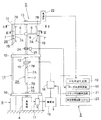
図1〜図3は、本発明の方法を実施するようになっている多段縦軸風力発電装置(以下、風力発電装置と略称する)の第1の実施形態を示し、この実施形態の風力発電装置1は、多段縦軸風車を構成する上下2段の縦軸型ロータ、すなわち下段の第1ロータ2A及び上段の第2ロータ2Bと、発電機4と、制御手段5とを備えている。
1 to 3 show a first embodiment of a multistage vertical wind power generator (hereinafter abbreviated as a wind power generator) adapted to carry out the method of the present invention. The
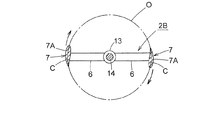
第1及び第2ロータ2A、2Bは、それぞれ、水平面上において外側方を向き、かつ一直線上に並ぶ水平アーム6、6と、両水平アーム6の外端部に上下方向の中央部の内面が固着され、後述する縦主軸14周りに回転する縦長の揚力型ブレード(以下ブレードと略称する)7、7と、外周面が両水平アーム6の内端部に固着された円筒形の回転軸8、8とを備えている。水平アーム6及びブレード7は、例えば繊維強化合成樹脂により形成されている。なお、水平アーム6とブレード7とは、一体成形が可能である。
Each of the first and
基礎9の上面には、平面視方形に枠組みされた上下複数(実施例では3個)の軸部支持枠10を有する支持枠体11が立設され、各軸部支持枠10の内部の平面視十字形をなす軸支持杆12の中心に圧嵌された軸受13には、縦主軸14の上下3箇所が、回転自在に支持されている。
On the upper surface of the
支持枠体11の内部に配置された第1、第2ロータ2A、2Bの回転軸8、8は、縦主軸14の上下部に、セレーション等により、相対回転不能に結合されている。なお、図2に示すように、第1、第2のロータ2A、2Bにおけるブレード7の平面位相は、上下のブレード7が重ならないように、例えば円周方向(回転方向)に90度異ならせてある。このようにすると、変化する風向きに上下のブレード7が対応して回転するので、第1、第2のロータ2A、2Bは効率よく回転する。
The
第1ロータ2Aは、その回転により発電機4を駆動させうるように、縦主軸14に常時連結されている。第1、第2ロータ2A、2B間において縦主軸14の中間部には、電磁クラッチ15が設けられ、第2ロータ2Bは、電磁クラッチ15を介して、縦主軸14及び第1ロータ2Aに断続可能に連結されている。なお、電磁クラッチ15が接続されるタイミングは、第1、第2ロータ2A、2Bのブレード7の位相が90度異なったときに行われる。この際の第1、第2ロータ2A、2Bのブレード7の回転方向の相対位相は、例えば図示しない非接触式の位置検知センサ等により検知することができる。
The
電磁クラッチ15としては、例えば、若干滑りながら、すなわち半クラッチ状態を経て接続される公知の摩擦式のものを使用するのが好ましい。この電磁クラッチ15により、接続時の衝撃トルクが緩和されるので、第2ロータ2Bの回転駆動力を縦主軸14にスムーズに伝達することができる。
電磁クラッチ15へは、後述する蓄電池18に接続された給電器16を介して給電されるようになっている。なお、蓄電池18の電力が不足している場合には、他の電源、例えば交流100V電源を直流に変換するなどして、電磁クラッチ15を作動させることができる。
As the electromagnetic clutch 15, for example, it is preferable to use a known friction type that is connected slightly through a slip, that is, through a half-clutch state. The
Electric power is supplied to the
第1、第2ロータ2A、2Bのブレード7の形状は、本願の発明者が開発した、特許第4907073号公報、特開2011−169292号公報に記載されているブレードと実質的に同形をなしている。
すなわち、ブレード7の弦長は、ブレード7の回転半径の20%〜50%とされ、翼面積は大きく設定されている。
The shapes of the
That is, the chord length of the
ブレード7における上下両端部を除く主部7Aの横断面の形状は、図3に拡大して示すように、主部7Aの翼厚中心線Cの内方と外方における翼厚を、互いに対称的にほぼ等寸とし、かつ翼厚中心線Cは、ブレード7の翼厚中心の回転軌跡Oとほぼ重なるように設定してある。
The cross-sectional shape of the
主部7A全体の平面形は、図2に示すように、翼厚中心の回転軌跡Oに沿うように円弧状に湾曲され、その内側面は、前縁の膨らみ部分から後縁にかけて、遠心方向へ傾斜しており、後方から内側面に風が当たると、前方へ押されるようになっている。
As shown in FIG. 2, the planar shape of the entire
主部7Aの横断面の形状は、回転方向である前側の翼厚が厚く、後方に向かって漸次薄くなる標準翼型に近いものとされている。
The shape of the cross section of the
ブレード7が、その前縁方向を前として回転すると、ブレード7の内外の回転半径の差によって、内側面に比して外側面の周速度が大となり、外側面に沿って後方へ通過する気流の方が、内側面におけるそれよりも高速となる。
When the
そのため、ブレード7の後縁部において、外側面を通過する気流の圧力は、内側面を通過する気流のそれよりも小となり、外側面におけるコアンダ効果によって、ブレード7の後縁部の外側面が、後方から前縁部方向に押されて、ブレード7に回転方向の推力が作用し、ブレード7の回転は促進される。
Therefore, the pressure of the airflow passing through the outer surface at the rear edge portion of the
図1及び図2に示すように、ブレード7の上下両端部には、内方、すなわち縦主軸14方向に向かって、円弧状に傾斜する内向き傾斜部7B、7Bが形成されているため、ブレード7の回転に伴い、主部7Aの内側面に沿って上下方向に拡散する気流は、内向き傾斜部7Bにより受止めて回転力を高めることとなる。
As shown in FIGS. 1 and 2, inwardly
また、主部7Aの内外の側面に沿って上下方向へ流れる気流は、コアンダ効果により、上下の内向き傾斜部7B、7Bの内面及び外面に沿って、後方に向かって通過するようになるので、第1、第2ロータ2A、2Bは、比較的低い風速下においても高い回転効率をもって回転する。
Further, the airflow flowing in the vertical direction along the inner and outer side surfaces of the
発電機4は、基礎9に設置され、その上下方向のロータ軸(図示略)に縦主軸14の下端部が連結されている。
発電機4としては、例えば、公知の単相交流発電機または三相交流発電機が使用され、発電機4により発電された電力は、整流器、電圧レギュレータ等(図示略)を有するコントローラ17を介して、蓄電池18に蓄電された後、蓄電池18から外部の直流負荷電源に給電されるか、コントローラ17から外部の交流負荷電力系統に直接給電される。
The
As the
コントローラ17は、発電機4からの出力発電量を調節して、蓄電池18または直流負荷電源へ出力する電流や電圧を制御可能である。なお、発電機4は、蓄電池18や直流負荷電源系統に直接電力を供給しうる直流発電機としてもよい。
The
制御手段5は、平均風速判定部19と、ロータ周速判定部20と、クラッチ切替判定部21とを備えている。
平均風速判定部19は、第1、第2ロータ2A、2Bに向かう風の一定時間毎の平均風速を検知するための、風速検知手段である風速計22に接続され、風速計22により検出された平均風速は、平均風速判定部19に入力され、制御手段5の中央処理装置(CPU)23により演算処理される。風速が予め定めた平均風速以下であると判定された場合に、判定信号は、クラッチ切替判定部21に出力される。なお、風速計22による平均風速の検知時間は、例えば10秒以下の比較的短い間隔で行うのが好ましい。
The control means 5 includes an average wind
The average wind
詳細な説明は後述するが、クラッチ切替判定部21は、風速計22が予め定めた平均風速以下、例えばカットイン風速である2m/s以下を検知した場合に、給電器16に判定信号を出力し、給電器16からの給電を停止して電磁クラッチ15を切断する。これにより、第2ロータ2Bの回転駆動力が縦主軸14に伝達されなくなるとともに、第2ロータ2Bは空転するようになる。
また、クラッチ切替判定部21へは、後述する回転速度検出センサ25からロータ周速判定部20に入力されるデータに基づいても、判定信号が出力される。
Although detailed description will be given later, the clutch
A determination signal is also output to the clutch
第2ロータ2Bと電磁クラッチ15との間の縦主軸14には、第2ロータ2Bの回転速度を測定するための平歯車24が取付けられており、この平歯車24の回転数を、回転速度検出センサ25をもって検出することにより、縦主軸14を介して第2ロータ2Bの回転速度を検出しうるようになっている。なお、平歯車24に代えて、縦主軸14の外周面に、例えば1個または複数個の凸部を設けてもよい。
回転速度検出センサ25としては、例えば磁気回転速度検出センサ、超音波回転速度検出センサ、ロータリエンコーダ等の非接触型センサが用いられる。
A
As the rotational
回転速度検出センサ25により検出された縦主軸14の回転速度は、制御手段5のロータ周速判定部20に入力され、入力された回転速度に基づいて、制御手段5の中央処理装置23は第2ロータ2Bの平均周速を演算する。すなわち、ブレード7の回転半径(r)から、第2ロータ2Bの外周の長さ(2πr)が確定されるので、その外周の長さ(2πr)に縦主軸14の回転速度(rpm)を乗じれば、周速(m/s)が得られる。上記の回転速度検出センサ25とロータ周速判定部20とにより、回転速度検知手段が構成される。
The rotational speed of the vertical
なお、第2ロータ2Bの周速は、ブレード7の角速度を、センサにより検出することによっても求めることができる。すなわち、ブレード7の角速度(rad/s)に、その回転半径(r)を乗じた値が、第2ロータ2Bの周速となる。
The peripheral speed of the
ロータ周速判定部20により、空転している第2ロータ2Bの平均周速が、該第2ロータ2Bが自力で加速して回転する特定の値(例えば5m/s)に達したと判定された場合には、ロータ周速判定部20からクラッチ切替判定部21に出力される判定信号に基づいて、給電器16から電磁クラッチ15に給電され、電磁クラッチ15がONすることにより、第2ロータ2Bの回転駆動力が縦主軸14を介して第1ロータ2Aに伝達される。これにより、速い周速で空転している第2ロータ2Bの回転駆動力により第1ロータ2Aの回転速度が増速させられ、平均風速が2m/s以下の低風速下においても、第1、第2ロータ2A、2Bの回転速度が共に上昇する。従って、発電機4のコギングトルクや発電負荷により、第1、第2ロータ2A、2Bが失速を起こすのが未然に防止され、効率よく発電することが可能となる。
The rotor peripheral
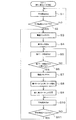
次に、上記第1の実施形態に係る風力発電装置1を用いた風力発電方法について、図4に示すフローチャートを参照して説明する。
まず、第1ロータ2Aと第2ロータ2Bの回転が縦主軸14に伝達されるように、電磁クラッチ15を接続し、両ロータ2A、2Bの回転駆動力により発電機4を作動させている状態で、第1、第2ロータ2A、2Bの平均風速を、風速計22により測定し(S1)、その計測値に基づいて、制御手段5の平均風速判定部19及び中央処理装置23が、平均風速がカットイン風速である2m/s以下(0を含む)であるか否かを判定する(S2)。
Next, a wind power generation method using the
First, the
平均風速がカットイン風速である2m/s以下と判定された場合には、制御手段5の平均風速判定部19からクラッチ切替判定部21に判定信号が出力され、その判定信号により、給電器16から電磁クラッチ15への給電が停止されることにより、電磁クラッチ15はOFFとなる(S3)。これにより、第2ロータ2Bの回転駆動力が縦主軸14に伝達されなくなるとともに、第2ロータ2Bは空転する(S4)。
When it is determined that the average wind speed is 2 m / s or less, which is the cut-in wind speed, a determination signal is output from the average wind
なお、平均風速が2m/s以下と判定された場合に、電磁クラッチ15をOFFとして第2ロータ2Bを空転させるのは、2m/s以下の低風速では、第1、第2ロータ2A、2Bが発電機4のコギングトルクや発電負荷の影響を受けて失速するおそれがあり、効率よく発電することができないからである。
When the average wind speed is determined to be 2 m / s or less, the
電磁クラッチ15をOFFとして、第2ロータ2Bの回転駆動力が縦主軸14に伝達されなくすると、第2ロータ2Bは抵抗なく円滑に空転し、2m/s以下の低風速でも、第2ロータ2Bは失速することなく慣性で回転し続ける。従って、第2ロータ2Bが空転している時に風況が少しでもよくなると、第2ロータ2Bはさらに加速されて空転するようになる。
When the
第2ロータ2Bが空転しているときの平均周速を、回転速度検出センサ25から出力されるデータに基づいて、ロータ周速判定部20及び中央処理装置23が測定し(S5)、第2ロータ2Bの平均周速が例えば5m/sに達したか否かを判定する(S6)。
Based on the data output from the rotational
第2ロータ2Bの平均周速が5m/sに達した場合には、クラッチ切替判定部21より給電器16に出力される給電信号により、電磁クラッチ15がONとなり(S7)、速い周速で空転している第2ロータ2Bの回転駆動力が縦主軸14に伝達されて、第1ロータ2Aの回転速度が増速される(S8)。これにより、第1、第2ロータ2A、2Bが失速するのが防止され、回転速度が上昇された両ロータ2,3の回転駆動トルクにより発電機4が駆動されて、効率よく発電される(S9)。なお、第2ロータ2Bの平均周速が5m/sに達していないと判定された場合は、ステップS5に戻り、引き続き第2ロータ2Bの平均周速を測定する。
When the average peripheral speed of the
第2ロータ2Bの平均周速が5m/sに達したか否かを判定する理由は、上述した形状の揚力型ブレード7を備える縦軸型ロータにおいては、第2ロータ2Bの平均周速が5m/sに達すると、ブレード7の上下両端部の内向き傾斜部7Bの作用とコアンダ効果により、ブレード7に生じる揚力(推力)が増加し、第2ロータ2Bは、風速を超える周速に自力で加速しながら効率よく空転するからである。
The reason why it is determined whether or not the average peripheral speed of the
このように、第2ロータ2Bの平均周速が5m/sに達し、第2ロータ2Bが自力で加速しながら効率よく空転しているときに、電磁クラッチ15をONとして第2ロータ2Bの回転駆動力を縦主軸14に伝達し、第1ロータ2Aの回転速度を増速するようにすると、低風速下において、第1、第2ロータ2A、2Bが、発電機4のコギングトルクや発電負荷によって失速するおそれがなくなるので、発電効率を高めることができる。
Thus, when the average peripheral speed of the
なお、周速が5m/sの場合の第2ロータ2Bの回転速度を例示すると、周速、回転速度及び外周の長さには、前述したような関係があるので、例えばブレード7の回転半径(r)を1mとした場合、第2ロータ2Bの外周の長さ(2πr)は6.28mとなる。従って、周速5m/sを、外周の長さ6.28mで割り、60を乗じて分速に換算すれば、第2ロータ2Bの回転速度は約48rpmとなる。
In addition, when the rotational speed of the
第1、第2ロータ2A、2Bの回転により発電しているときに、風速計22により再度平均風速を測定し(S10)、平均風速判定部19が平均風速2m/s以下を再度検知した場合(S11)には、ステップS3に戻り、前述と同様に、電磁クラッチ15をOFFとして、再度第2ロータ2Bを空転させる(S4)。このステップS3〜S11をループ状に繰り返すことにより、発電効率を大幅に高めることができる。
When power is generated by the rotation of the first and
以上説明したように、上記第1の実施形態に係る風力発電装置1を用いた風力発電方法においては、発電機4に接続された縦主軸14に、第1ロータ2Aを常時連結するとともに、第2ロータ2Bを、電磁クラッチ15を介して断続可能に連結し、第1、第2ロータ2A、2Bがカットイン風速である平均風速2m/s以下の低風速下で回転している場合に、制御手段5により電磁クラッチ15を切断して第2ロータ2Bを空転させ、第2ロータ2Bが自力で加速しながら効率よく回転しうる平均周速である5m/sに達したときに、電磁クラッチ15を接続して、空転している第2ロータ2Bの回転駆動力により第1ロータ2Aの回転を増速させて発電するように制御し、かつ第1、第2ロータ2A、2Bが再度平均風速2m/s以下の低風速で回転するようになったときに、制御手段5により電磁クラッチ15を再度切断して、第2ロータ2Bが自力で加速しながら効率よく回転しうる平均周速である5m/sに達するまで空転させたのち、電磁クラッチ15を再度接続して、空転させた第2ロータ2Bの回転駆動力により第1ロータ2Aの回転を増速させながら、第1、第2ロータ2A、2Bの回転駆動力により発電するように繰り返し制御するので、低風速下においても、第1、第2ロータ2A、2Bが発電機4のコギングトルクや発電負荷により失速するのを未然に防止しながら、効率よく発電することができる。
As described above, in the wind power generation method using the
また、第1、第2ロータ2A、2Bの失速が防止されるので、発電容量の大きな発電機4を使用して、より発電効率を高めることが可能となる。
Moreover, since the stall of the first and
さらに、第1ロータ2Aは、発電機4に接続された縦主軸14に常時連結されているので、第2ロータ2Bが空転している間も、第1ロータ2Aが回転している限り、発電が停止されることはない。
Further, since the
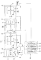
次に、図5を参照して、本発明の方法の実施に用いられる風力発電装置の第2の実施形態について説明する。なお、前記第1の実施形態の風力発電装置1と同様の部材には、同じ符号を付すに止めて、詳細な説明を省略する。
Next, with reference to FIG. 5, a second embodiment of the wind turbine generator used for carrying out the method of the present invention will be described. In addition, the same code | symbol is attached | subjected to the member similar to the
第2の実施形態の風力発電装置は、前記第1の実施形態の第2ロータ2Bの上方に、第3ロータ2Cを追加し、上下3段の縦軸型風車を備えるものとしたものである。すなわち、支持枠体11を上方に延長して高くするとともに、その上端部に設けた軸部支持枠10の中央に設けた軸受13より、上下寸法を大とした縦主軸14の上端部を回転自在に支持し、第2ロータ2Bよりも上方の縦主軸14に、第3ロータ2Cを相対回転不能として取付けてある。第3ロータ2Cのブレード7の平面位相は、第2ロータ2Bのブレード7に対し60度異ならせてある。
In the wind turbine generator of the second embodiment, a
最下段の第1ロータ2Aは、第1の実施形態と同様に、縦主軸14に常時連結されている。中段の第2ロータ2Bと最上段の第3ロータ2Cは、最下段の第1ロータ2Aと中段の第2ロータ2B間において縦主軸14に設けた電磁クラッチ15を介して、縦主軸14及び第1ロータ2Aに断続可能に連結されている。なお、この実施形態のような上下3段の縦軸型風車を備える場合、電磁クラッチ15が接続されるタイミングは、第1、第2ロータ2A、2Bのブレード7の位相が60度異なったときに行われる。
The lowermost
電磁クラッチ15と第2ロータ2Bとの間の縦主軸14には、第2ロータ2Bと第3ロータ2Cの回転速度を測定するための平歯車24が取付けられ、この平歯車24の回転数を、回転速度検出センサ25により検出し、制御手段5のロータ周速判定部20に出力されるようになっている。
A
第2の実施形態に係る風力発電装置においては、第1〜第3ロータ2A、2B、2Cがカットイン風速である平均風速2m/s以下の低風速下で回転している場合に、制御手段5により電磁クラッチ15を切断して、第2、第3ロータ2B、2Cを空転させ、第2、第3ロータ2B、2Cが自力で加速しながら効率よく回転しうる平均周速である5m/sに達したときに、電磁クラッチ15を接続して、空転している第2、第3ロータ2B、2Cの回転駆動力により第1ロータ2Aの回転速度を増速させて発電するように制御し、かつ第1〜第3ロータ2A、2B、2Cが再度平均風速2m/s以下の低風速で回転するようになったときに、制御手段5により電磁クラッチ15を再度切断して、第2、第3ロータ2B、2Cが自力で加速しながら効率よく回転しうる平均周速である5m/sに達するまで空転させたのち、電磁クラッチ15を再度接続して、空転させた第2、第3ロータ2B、2Cの回転駆動力により第1ロータ2Aの回転速度を増速させながら、第1〜第3ロータ2A、2B、2Cの全てのロータの回転により発電するように繰り返し制御するようになっている。
In the wind turbine generator according to the second embodiment, when the first to
第2の実施形態に係る風力発電装置においては、第2、第3ロータ2B、2Cの上下2段のロータを空転させるので、第1ロータ2Aを増速させる際の回転駆動トルクが増大し、第1ロータ2Aを速やかに増速させることができる。
In the wind turbine generator according to the second embodiment, since the upper and lower rotors of the second and
なお、図5の2点鎖線で示すように、第2ロータ2Bと第3ロータ2C間において縦主軸14にも、電磁クラッチ15を設け、上下の電磁クラッチ15、15を同期して断続させるようにしてもよい。
As indicated by a two-dot chain line in FIG. 5, an
このようにすると、上下の電磁クラッチ15を切断したとき、第2ロータ2Bと第3ロータ2Cとが、風速に対応して独立して抵抗なく空転するとともに、一般に地上からの高さが高いほど風速が速くなる傾向があるので、最上段の第3ロータ2Cは、予め定めた周速まで速やかに空転する。従って、電磁クラッチ15を接続すると、第3ロータ2Cの回転駆動力が第2ロータ2Bに伝達され、互いに加速し合って回転するので、第2、第3ロータ2B、2Cの回転駆動力により、最下段の第1ロータ2Aを効率よく、かつ速やかに増速させて発電することができる。
In this way, when the upper and lower
また、上記したように、地上からの高さが高いほど風速が速く、最上段の第3ロータ2Cは効率よく回転するので、第2ロータ2Bと第3ロータ2C間の縦主軸14に電磁クラッチ15を設けて、第3ロータ2Cのみが空転するようにし、この第3ロータ2Cの回転駆動力により、第1、第2ロータ2A、2Bを増速させて発電するようにしてもよい。
Further, as described above, the higher the height from the ground, the faster the wind speed, and the uppermost
次に、図6を参照して、本発明の方法の実施に用いられる風力発電装置の第3の実施形態について説明する。なお、前記第2の実施形態の風力発電装置と同様の部材には、同じ符号を付すに止めて、詳細な説明を省略する。 Next, with reference to FIG. 6, a third embodiment of the wind turbine generator used for carrying out the method of the present invention will be described. In addition, the same code | symbol is attached | subjected to the member similar to the wind power generator of the said 2nd Embodiment, and detailed description is abbreviate | omitted.
第3の実施形態の風力発電装置においては、第2の実施形態の風力発電装置の電磁クラッチ15に代えて、遠心クラッチ26を用いている。図6に略示する遠心クラッチ26は、例えば次のように構成されている。
In the wind turbine generator of the third embodiment, a centrifugal clutch 26 is used instead of the
すなわち、第1、第2ロータ2A、2B間において縦主軸14を2分割し、第2ロータ2B側の縦主軸14に、外周面に摩擦材を固着した複数のウエイト27、27を、遠心力によって半径方向外側に移動しうるように取付けるとともに、発電機4に常時連結された第1ロータ2A側の縦主軸14に、上面が閉塞された円筒形の従動ドラム28を、内部にウエイト27が収容されるように固着してある。
That is, the longitudinal
第3の実施形態の風力発電装置を用いて発電を行う場合、次のようにして行われる。
遠心クラッチ26は、ウエイト27に作用する遠心力が小さい場合、すなわち第1〜第3ロータ2A、2B、2Cがカットイン風速である平均風速2m/s以下の低風速で回転している場合に、ウエイト28は従動ドラム29の内面から離間するように設定されている。従って、平均風速が2m/s以下の場合には、遠心クラッチ26は自動的に切れ、第2、第3ロータ2B、2Cの回転駆動力が縦主軸14及び第1ロータ2Aに伝達されなくなるとともに、第2、第3ロータ2B、2Cは空転することとなる。
When power generation is performed using the wind turbine generator of the third embodiment, it is performed as follows.
When the centrifugal force acting on the
また、空転している第2、第3ロータ2B、2Cの平均周速が例えば5m/sに達した場合、すなわち、5m/sの平均周速のときの縦主軸14の回転速度が、予め定めた値に達した場合には、ウエイト27が遠心力により従動ドラム28の内面に接触し、遠心クラッチ26が自動的に接続されるように設定されている。従って、空転している第2、第3ロータ2B、2Cの平均周速が例えば5m/sに達すると、それらの回転駆動力が第1ロータ2A側の縦主軸14に伝達されて、第1ロータ2Aの回転が増速されるようになる。
In addition, when the average peripheral speed of the second and
第3の実施形態の風力発電装置においても、平均風速が2m/s以下の低風速になると、遠心クラッチ26が自動的に切断されて第2、第3ロータ2B、2Cが空転し、平均周速が5m/sに達して第2、第3ロータ2B、2Cが自力で加速しながら回転するようになると、遠心クラッチ26が自動的に接続されて、空転している第2、第3ロータ2B、2Cの回転駆動力により、第1ロータ2Aの回転が増速され、第1〜第3ロータ2A、2B、2Cの全てのロータにより発電機4を駆動して発電されるようになっているので、上記実施形態と同様に、低風速下において第1〜第3ロータ2A、2B、2Cが発電機4のコギングトルクや発電負荷により失速するのを未然に防止しながら、効率よく発電することができる。
Also in the wind turbine generator of the third embodiment, when the average wind speed becomes a low wind speed of 2 m / s or less, the centrifugal clutch 26 is automatically disconnected, and the second and
また、機械的な遠心クラッチ26を用いると、第1、第2の実施形態のような、電磁クラッチ14をON、OFF制御するための制御手段5等が不要となるので、安価な風力発電装置を提供することができる。 Further, when the mechanical centrifugal clutch 26 is used, the control means 5 for controlling the ON / OFF of the electromagnetic clutch 14 as in the first and second embodiments becomes unnecessary, so that an inexpensive wind power generator is provided. Can be provided.
本発明は、上記実施形態に限定されるものではなく、本発明の要旨を逸脱しない範囲内で、例えば次のような種々の変形や変更を施すことが可能である。 The present invention is not limited to the above embodiment, and various modifications and changes such as the following can be made without departing from the spirit of the present invention.
上記第1、第2の実施形態では、平均風速が2m/s以下と判定された場合に、電磁クラッチ15をOFFとして、第2ロータ2Bまたは第2、第3ロータ2B、2Cを空転させるようにしているが、平均風速が2m/s以下のときの縦主軸14の平均回転速度、または全てのロータの平均周速が予め定めた値となったときに、電磁クラッチ15をOFFとするようにしてもよい。
In the first and second embodiments, when the average wind speed is determined to be 2 m / s or less, the
また、空転させた第2、第3ロータ2B、2Cの平均周速が5m/sに達したとき、電磁クラッチ15をONとして、第1ロータ2Aの回転を増速するようにしたが、前述したように、ロータの周速は回転速度に換算できるため、平均周速が5m/sに達したときの第2、第3ロータ2B、2Cの回転速度を回転速度センサ25が検出したときに、電磁クラッチ15をONとして、第1ロータ2Aの回転を増速するようにすることもできる。
Further, when the average peripheral speed of the idled second and
さらに、電磁クラッチ15をOFFとする平均風速を2m/s以下としたが、この際の平均風速の上限値は、ブレード7の回転半径の大小に対応して適切に設定される。
例えば、ブレード7の回転半径が上記実施形態の1mより小さい場合には、各ロータの回転トルクが小さくなって、コギングトルクや発電負荷の影響を受けやすくなるので、電磁クラッチ15をOFFとする平均風速の上限値を2m/s以上に設定すればよい。
Furthermore, although the average wind speed at which the
For example, when the rotational radius of the
また、ブレード7の回転半径が1mより大きい場合には、ロータの回転速度が低くても、回転トルクが大となってコギングトルクや発電負荷の影響を受けにくくなるので、電磁クラッチ15をOFFとする平均風速の上限値を2m/s以下に設定すればよい。
Further, when the rotational radius of the
上記実施形態では、空転している第2、第3ロータ2B、2Cの平均周速が5m/sに達したときに、電磁クラッチ15をONとするようにしたが、この場合の平均周速の値は、ブレード7の回転半径の大小に応じて適切に設定される。
In the above embodiment, the
上記第1、第2実施形態では、最下段と上段のロータの回転駆動力を断続するのに、電磁クラッチ15を用いているが、例えば制御手段5によりON、OFF制御可能な電動式のアクチュエータを備える摩擦クラッチや噛合クラッチ等を用いることもできる。
In the first and second embodiments, the
上記実施形態では、最下段の第1ロータ2Aを、縦主軸14を介して常時発電機4の連結しているが、第1の実施形態の風力発電装置の場合には、第2ロータ2Bが連結されている縦主軸14の上端部を、支持枠体11の上部等に設置した発電機に常時連結し、第1ロータ2Aを電磁クラッチ15を介して空転させうるようにしてもよい。
In the above embodiment, the lowermost
また、第2の実施形態の風力発電装置の場合には、最上段の第3ロータ2Cが連結されている縦主軸14の上端部を、支持枠体11の上部等に設置した発電機に常時連結し、最下段の第1ロータ2Aと中段の第2ロータ2Bとを、電磁クラッチ15を介して空転させうるようにするか、または、中段の第2ロータ2Bが連結されている縦主軸14の適所に、プーリやスプロケットを取り付けて、それらに接続したベルトやチェーン等の伝動手段を介して、縦主軸14の側方に配置した発電機を駆動するようにし、最下段の第1ロータ2Aと最上段の第3ロータ2Cとを、電磁クラッチ15を介して空転させうるようにしてもよい。
In the case of the wind turbine generator of the second embodiment, the upper end of the vertical
さらに、第3の実施形態の風力発電装置の場合には、最上段の第3ロータ2Cが連結されている縦主軸14の上端部を、支持枠体11の上部等に設置した発電機に常時連結し、最下段の第1ロータ2Aと中段の第2ロータ2Bとを、遠心クラッチ26を介して空転させうるようにしてもよい。
Furthermore, in the case of the wind turbine generator according to the third embodiment, the upper end of the vertical
本発明は、3段以上のロータを備える風力発電装置にも適用しうることは言うまでもない。 Needless to say, the present invention can also be applied to a wind turbine generator having three or more stages of rotors.
1 風力発電装置
2A 第1ロータ
2B 第2ロータ
2C 第3ロータ
4 発電機
5 制御手段
6 水平アーム
7 揚力型ブレード
7A 主部
7B 内向き傾斜部
8 回転軸
9 基礎
10 軸部支持枠
11 支持枠体
12 軸支持杆
13 軸受
14 縦主軸
15 電磁クラッチ
16 給電器
17 コントローラ
18 蓄電池
19 平均風速判定部
20 ロータ周速判定部
21 クラッチ切替判定部
22 風速計(風速検知手段)
23 中央処理装置
24 平歯車
25 回転速度検出センサ
26 遠心クラッチ
27 ウエイト
28 従動ドラム
C 翼厚中心線
O 回転軌跡
DESCRIPTION OF
23
Claims (4)
前記複数段のロータが予め定めた平均風速以下で回転している場合に、前記クラッチを切断して前記他のロータの少なくとも一つを空転させ、
このロータが加速して回転する特定の周速または回転速度に達したとき、前記クラッチを接続して前記空転させたロータにより前記縦主軸に常時連結されたロータを増速させて前記発電機により発電するようにし、
前記複数段のロータが再度、前記平均風速以下で回転するようになったとき、前記クラッチを再度切断して、前記他のロータの少なくとも一つを前記特定の周速または回転速度に達するまで空転させ、
前記クラッチを再度接続して前記空転させたロータにより前記縦主軸に常時連結されたロータを再度増速させて発電することを繰返えさせることを特徴とする多段縦軸風車における風力発電方法。 At least one of a plurality of upper and lower rotors having a plurality of vertically long lift-type blades rotating around the vertical main shaft is always connected to the vertical main shaft linked to the generator, and at least one of the other rotors is connected. Connected through a clutch,
When the plurality of rotors are rotating at a predetermined average wind speed or less, the clutch is disengaged to idle at least one of the other rotors,
When a specific peripheral speed or rotational speed at which the rotor is accelerated and rotates is reached, the rotor always connected to the longitudinal main shaft is accelerated by the idled rotor connected to the clutch, and the generator To generate electricity,
When the plurality of rotors rotate again below the average wind speed, the clutch is disengaged again, and at least one of the other rotors is idled until the specific circumferential speed or rotational speed is reached. Let
A method for wind power generation in a multistage vertical wind turbine, characterized in that power generation is repeated by increasing the speed of a rotor always connected to the longitudinal main shaft again by the idled rotor after the clutch is reconnected.
Priority Applications (2)
| Application Number | Priority Date | Filing Date | Title |
|---|---|---|---|
| JP2016049107A JP6714398B2 (en) | 2016-03-14 | 2016-03-14 | Wind power generation method in multi-stage vertical wind turbine |
| PCT/JP2017/009620 WO2017159550A1 (en) | 2016-03-14 | 2017-03-09 | Method for generating wind power using multi-stage vertical axis wind turbine, and multi-stage vertical axis wind power generation device |
Applications Claiming Priority (1)
| Application Number | Priority Date | Filing Date | Title |
|---|---|---|---|
| JP2016049107A JP6714398B2 (en) | 2016-03-14 | 2016-03-14 | Wind power generation method in multi-stage vertical wind turbine |
Publications (2)
| Publication Number | Publication Date |
|---|---|
| JP2017166325A true JP2017166325A (en) | 2017-09-21 |
| JP6714398B2 JP6714398B2 (en) | 2020-06-24 |
Family
ID=59909925
Family Applications (1)
| Application Number | Title | Priority Date | Filing Date |
|---|---|---|---|
| JP2016049107A Active JP6714398B2 (en) | 2016-03-14 | 2016-03-14 | Wind power generation method in multi-stage vertical wind turbine |
Country Status (1)
| Country | Link |
|---|---|
| JP (1) | JP6714398B2 (en) |
Cited By (3)
| Publication number | Priority date | Publication date | Assignee | Title |
|---|---|---|---|---|
| US20160333851A1 (en) * | 2014-01-09 | 2016-11-17 | Nam-Kyu CHOI | Wind power generating apparatus |
| WO2019129049A1 (en) * | 2017-12-27 | 2019-07-04 | 胡国祥 | Vertical axis wind turbine having two oppositely rotating impellers constructed along the same axis |
| WO2019235343A1 (en) * | 2018-06-08 | 2019-12-12 | 株式会社グローバルエナジー | Vertical axis windmill, oblong blade for vertical axis windmill, and wind power generation device |
Citations (2)
| Publication number | Priority date | Publication date | Assignee | Title |
|---|---|---|---|---|
| JPS5566669A (en) * | 1978-11-14 | 1980-05-20 | Chuji Saito | Wind power generator |
| JP2006118384A (en) * | 2004-10-20 | 2006-05-11 | Fjc:Kk | Vertical-shaft windmill |
-
2016
- 2016-03-14 JP JP2016049107A patent/JP6714398B2/en active Active
Patent Citations (2)
| Publication number | Priority date | Publication date | Assignee | Title |
|---|---|---|---|---|
| JPS5566669A (en) * | 1978-11-14 | 1980-05-20 | Chuji Saito | Wind power generator |
| JP2006118384A (en) * | 2004-10-20 | 2006-05-11 | Fjc:Kk | Vertical-shaft windmill |
Cited By (6)
| Publication number | Priority date | Publication date | Assignee | Title |
|---|---|---|---|---|
| US20160333851A1 (en) * | 2014-01-09 | 2016-11-17 | Nam-Kyu CHOI | Wind power generating apparatus |
| WO2019129049A1 (en) * | 2017-12-27 | 2019-07-04 | 胡国祥 | Vertical axis wind turbine having two oppositely rotating impellers constructed along the same axis |
| WO2019235343A1 (en) * | 2018-06-08 | 2019-12-12 | 株式会社グローバルエナジー | Vertical axis windmill, oblong blade for vertical axis windmill, and wind power generation device |
| JP2019210919A (en) * | 2018-06-08 | 2019-12-12 | 株式会社グローバルエナジー | Vertical shaft windmill and vertically long blade and wind power generator |
| US11486353B2 (en) | 2018-06-08 | 2022-11-01 | Global Energy Co., Ltd. | Vertical blade having a vertical main part and an inwardly inclined part and a vertical shaft wind turbine using the vertical blade |
| US11635058B2 (en) | 2018-06-08 | 2023-04-25 | Global Energy Co. Ltd. | Vertical blade having a vertical main part and inwardly inclined parts and a vertical shaft wind turbine using the vertical blade |
Also Published As
| Publication number | Publication date |
|---|---|
| JP6714398B2 (en) | 2020-06-24 |
Similar Documents
| Publication | Publication Date | Title |
|---|---|---|
| JP7161827B2 (en) | Wind power generation method and wind power generation device | |
| CN103742362B (en) | Independent variable pitch control system and method for direct-drive permanent magnet wind generating set | |
| TWI726895B (en) | Rotation speed control method of windmill and wind power generation device | |
| CN104884791A (en) | Wind turbine yaw control systems | |
| JP2017166325A (en) | Wind power generation method in multistage vertical wind turbine | |
| CN108590963A (en) | A kind of variable speed drives control strategy of vertical axis windmill cylindrical rotor blade | |
| JP2018040306A (en) | Wind and water power generation device | |
| JP2017053304A5 (en) | ||
| JP2017053304A (en) | Wind power generator | |
| JP6917673B2 (en) | Windmill rotation speed control method | |
| JP2003284393A (en) | Wind power generator | |
| JP6649727B2 (en) | Wind power generator | |
| WO2017159550A1 (en) | Method for generating wind power using multi-stage vertical axis wind turbine, and multi-stage vertical axis wind power generation device | |
| JP2017172392A (en) | Multistage vertical shaft wind power generation device | |
| CN100374749C (en) | Auto clutch of verticl shaft wind-driven generator | |
| JP6609129B2 (en) | Wind power generator | |
| JP6774172B2 (en) | Wind power generation method | |
| JP2017053303A5 (en) | ||
| JP2017020374A5 (en) | ||
| JP6609128B2 (en) | Windmill rotational speed control method | |
| JP2017020373A5 (en) | ||
| KR101242766B1 (en) | wind-driven generator with Apparatus of reducing rotor load and method of reducing rotor load for wind-driven generator with Apparatus of reducing rotor load | |
| JP4040939B2 (en) | Wind power generation apparatus and wind power generation method using the same | |
| US20200102931A1 (en) | Wind Turbine | |
| Rosmin et al. | Power limitation at high wind speed for a variable speed fixed pitch wind turbine using close-loop scalar control |
Legal Events
| Date | Code | Title | Description |
|---|---|---|---|
| A711 | Notification of change in applicant |
Free format text: JAPANESE INTERMEDIATE CODE: A711 Effective date: 20190209 |
|
| A621 | Written request for application examination |
Free format text: JAPANESE INTERMEDIATE CODE: A621 Effective date: 20190226 |
|
| A131 | Notification of reasons for refusal |
Free format text: JAPANESE INTERMEDIATE CODE: A131 Effective date: 20200128 |
|
| A521 | Request for written amendment filed |
Free format text: JAPANESE INTERMEDIATE CODE: A523 Effective date: 20200305 |
|
| TRDD | Decision of grant or rejection written | ||
| A01 | Written decision to grant a patent or to grant a registration (utility model) |
Free format text: JAPANESE INTERMEDIATE CODE: A01 Effective date: 20200512 |
|
| A61 | First payment of annual fees (during grant procedure) |
Free format text: JAPANESE INTERMEDIATE CODE: A61 Effective date: 20200605 |
|
| R150 | Certificate of patent or registration of utility model |
Ref document number: 6714398 Country of ref document: JP Free format text: JAPANESE INTERMEDIATE CODE: R150 |
|
| R250 | Receipt of annual fees |
Free format text: JAPANESE INTERMEDIATE CODE: R250 |
|
| R250 | Receipt of annual fees |
Free format text: JAPANESE INTERMEDIATE CODE: R250 |
|
| R250 | Receipt of annual fees |
Free format text: JAPANESE INTERMEDIATE CODE: R250 |