JP2017166315A - Flush type toilet bowl - Google Patents
Flush type toilet bowl Download PDFInfo
- Publication number
- JP2017166315A JP2017166315A JP2017048898A JP2017048898A JP2017166315A JP 2017166315 A JP2017166315 A JP 2017166315A JP 2017048898 A JP2017048898 A JP 2017048898A JP 2017048898 A JP2017048898 A JP 2017048898A JP 2017166315 A JP2017166315 A JP 2017166315A
- Authority
- JP
- Japan
- Prior art keywords
- water
- drainage channel
- rim
- flush toilet
- channel
- Prior art date
- Legal status (The legal status is an assumption and is not a legal conclusion. Google has not performed a legal analysis and makes no representation as to the accuracy of the status listed.)
- Granted
Links
Images


Landscapes
- Sanitary Device For Flush Toilet (AREA)
- Producing Shaped Articles From Materials (AREA)
Abstract
【課題】リム吐水口から吐出される洗浄水によるボウル部の洗浄が終了した後、残水がリム吐水口から点滴してしまうことを抑制できる水洗式大便器を提供すること。【解決手段】本発明は、ボウル形状の汚物受け面と、当該汚物受け面の上縁部に形成されたリム部と、を有するボウル部と、前記リム部に設けられ、前記ボウル部内に洗浄水を吐水して当該洗浄水による旋回流を形成するリム吐水部と、前記汚物受け面の後方側に位置するリム通水開始領域まで洗浄水を導水する導水路と、前記導水路に接続され前記リム通水開始領域から前記リム吐水部まで洗浄水を導水するリム通水路と、前記ボウル部の下方に接続された排水路と、前記導水路から前記排水路に至る水抜流路と、を備えたことを特徴とする水洗式大便器である。【選択図】図2PROBLEM TO BE SOLVED: To provide a flush toilet capable of suppressing drip of residual water from a rim spout after cleaning of a bowl portion with washing water discharged from a rim spout. SOLUTION: The present invention is provided in a bowl portion having a bowl-shaped filth receiving surface and a rim portion formed on an upper edge portion of the filth receiving surface, and is provided in the rim portion and cleaned in the bowl portion. A rim spouting portion that spouts water to form a swirling flow by the washing water, a headrace that guides the washing water to the rim water flow start region located on the rear side of the filth receiving surface, and a headrace that is connected to the headrace. A rim water passage for guiding wash water from the rim water flow start region to the rim water discharge portion, a drainage channel connected below the bowl portion, and a drainage flow path from the headrace to the drainage channel. It is a water-washable stool that is characterized by being equipped. [Selection diagram] Fig. 2
Description
本発明は、水洗式大便器に係り、特に、洗浄水源から供給される洗浄水により便器本体を洗浄して汚物を排出する水洗式大便器に関する。 The present invention relates to a flush toilet bowl, and more particularly to a flush toilet bowl that flushes toilet bodies with flush water supplied from a flush water source and discharges filth.
従来から、例えば、特許文献1に記載されているように、リムの第1吐水口及び第2吐水口の2つのリム吐水口のみから洗浄水が吐水され、ボウル部の汚物受け面上に旋回流となって供給される水洗便器について知られている。この水洗便器では、リムの第1吐水口から流出され旋回する洗浄水が、ボウル部の後方領域に設けられた案内面により溜水部に向かう束状の流れとなり、排水路内に流入して、サイホン作用を発生させて汚物等を排出している。
Conventionally, for example, as described in
さらに、特許文献1の水洗便器を改良して、ボウル部内の浮遊系汚物を溜水内で上下方向に攪拌して排水路内へ効率よく排出するようにした水洗便器が、特許文献2に開示されている。
Further, a flush toilet in which the flush toilet in
本件発明者は、従来の水洗便器について、リム吐水口から吐出される洗浄水によるボウル部の洗浄が終了した後、残水がリム吐水口から点滴し、吐水(洗浄)が終了していないとの誤解を与える可能性があると共に、見映えが宜しくなく、また、残水の点滴によりボウル部に水垢が発生する懸念があることを把握した。 The inventor of the present invention, for a conventional flush toilet, after the cleaning of the bowl portion by the wash water discharged from the rim spout is finished, the remaining water is instilled from the rim spout and the water discharge (washing) is not finished. It has been found that there is a possibility that it may be misunderstood, that the appearance is not good, and that there is a concern that the drip of the bowl may be caused by drip of the remaining water.
そこで、本発明の目的は、リム吐水口から吐出される洗浄水によるボウル部の洗浄が終了した後、残水がリム吐水口から点滴してしまうことを抑制できる水洗式大便器を提供することである。 Accordingly, an object of the present invention is to provide a flush toilet that can suppress residual water from being instilled from the rim spout after the cleaning of the bowl portion by the wash water discharged from the rim spout is completed. It is.
本発明は、ボウル形状の汚物受け面と、当該汚物受け面の上縁部に形成されたリム部と、を有するボウル部と、前記リム部に設けられ、前記ボウル部内に洗浄水を吐水して当該洗浄水による旋回流を形成するリム吐水部と、前記汚物受け面の後方側に位置するリム通水開始領域まで洗浄水を導水する導水路と、前記導水路に接続され前記リム通水開始領域から前記リム吐水部まで洗浄水を導水するリム通水路と、前記ボウル部の下方に接続された排水路と、前記導水路から前記排水路に至る水抜流路と、を備えたことを特徴とする水洗式大便器である。 The present invention provides a bowl portion having a bowl-shaped filth receiving surface and a rim portion formed on an upper edge portion of the filth receiving surface, and provided in the rim portion, for discharging cleaning water into the bowl portion. A rim water spouting part that forms a swirling flow by the wash water, a water guide channel that guides the wash water to a rim water flow start region located on the rear side of the waste receiving surface, and the rim water feed connected to the water guide channel A rim water passage that guides cleaning water from a start region to the rim water spouting portion, a drain passage connected below the bowl portion, and a drain passage that extends from the water conduit to the drain passage. This is a flush toilet.
本発明によれば、導水路内の残水が、水抜流路を経て排水路に直接排水される。これにより、リム吐水口から吐出される洗浄水によるボウル部の洗浄が終了した後、残水がリム吐水口から点滴してしまうことを効果的に抑制することができる。 According to the present invention, the remaining water in the conduit is drained directly to the drainage channel via the drainage channel. Thereby, after the cleaning of the bowl portion by the cleaning water discharged from the rim water spouting port is finished, it is possible to effectively suppress the remaining water from being drip from the rim water spouting port.
また、本発明における導水路とは、汚物受け面の後方側に位置するリム通水開始領域まで洗浄水を導水するものであるから、当該導水路(例えばリム通水開始領域)から排水路に至る水抜流路の長さを、結果として短くすることができる。これにより、効果的な水抜作用を期待することができる。 Moreover, since the water conduit in the present invention is for guiding cleaning water to the rim water passage start region located on the rear side of the filth receiving surface, the water conduit (for example, the rim water passage start region) to the drain channel. As a result, the length of the drainage channel that reaches can be shortened. Thereby, an effective draining action can be expected.
好ましくは、導水路の底面は、水抜流路の入口開口に向けて、高さ位置が低くなっている。この場合、導水路の残水が効果的に水抜流路の入口開口に向けて案内されるため、導水路の残水がリム吐水口から点滴してしまうことを一層効果的に抑制することができる。 Preferably, the height of the bottom surface of the water conduit is lowered toward the inlet opening of the drainage channel. In this case, since the residual water in the water conduit is effectively guided toward the inlet opening of the drainage channel, it is possible to more effectively suppress the residual water in the water conduit from being drip from the rim spout. it can.
また、導水路は、凹部を有しており、水抜流路の入口開口は、当該凹部内に設けられていることが好ましい。この場合、当該凹部に残水が集められると水位に応じた水頭圧が作用するため、一層効果的な水抜作用を期待することができる。 Moreover, it is preferable that the water conduit has a recess, and the inlet opening of the drainage channel is provided in the recess. In this case, when residual water is collected in the concave portion, a water head pressure according to the water level acts, so that a more effective draining action can be expected.
また、好ましくは、リム通水路の底面は、導水路または水抜流路の入口開口に向けて、高さ位置が低くなっている。この場合、リム通水路の残水が効果的に導水路ないし水抜流路の入口開口に向けて案内されるため、リム通水路の残水がリム吐水口から点滴してしまうことを一層効果的に抑制することができる。 Preferably, the bottom surface of the rim water passage has a lower height position toward the inlet opening of the water conduit or the drainage channel. In this case, since the remaining water of the rim water channel is effectively guided toward the inlet opening of the water guide channel or the drainage channel, it is more effective that the remaining water of the rim water channel is instilled from the rim water outlet. Can be suppressed.
水抜流路の出口開口は、例えば、排水路の上面側の最下位置において開口されている。この場合、封水水位が低下して水抜流路を介して臭気が上がってきてしまうという懸念に対して、最も有効である。 The outlet opening of the drainage channel is opened, for example, at the lowest position on the upper surface side of the drainage channel. In this case, it is most effective against the concern that the sealing water level is lowered and the odor is increased through the drainage channel.
あるいは、水抜流路の出口開口は、排水路の上面側の最下位置よりも後方側において開口されており、水抜流路が当該出口開口の近傍領域で延びる方向は、当該出口開口に向かって後方向きである。この場合、水抜流路を通過してくる洗浄水が、封水を後方側(排出側)に向けて押し出すように作用するため、汚物、特に水の勢いに抗して浮遊してくる比較的微細な浮遊汚物の排出に効果的である。以下、この態様を「微弱サイホン」と呼んでいる。 Alternatively, the outlet opening of the drainage channel is opened on the rear side of the lowermost position on the upper surface side of the drainage channel, and the direction in which the drainage channel extends in the vicinity region of the outlet opening is toward the outlet opening. It is facing backwards. In this case, since the washing water passing through the drainage flow channel acts to push the sealed water toward the rear side (discharge side), the sewage, in particular, floats against the power of water. It is effective for discharging fine floating waste. Hereinafter, this mode is referred to as “weak siphon”.
あるいは、水抜流路の出口開口は、排水路の上面側の最下位置よりも前方側において開口されており、水抜流路が当該出口開口の近傍領域で延びる方向は、当該出口開口に向かって後方向きである。この場合も、水抜流路を通過してくる洗浄水が、封水を後方側(排出側)に向けて押し出すように作用するため、汚物、特に水の勢いに抗して浮遊してくる比較的微細な浮遊汚物の排出に効果的である(微弱サイホン)。 Alternatively, the outlet opening of the drainage channel is opened in front of the lowermost position on the upper surface side of the drainage channel, and the direction in which the drainage channel extends in the vicinity region of the outlet opening is toward the outlet opening. It is facing backwards. In this case as well, the washing water that passes through the drainage channel acts to push the sealed water toward the rear side (discharge side), so that the comparison is made against dirt, especially against the momentum of the water. It is effective for discharging fine floating waste (weak siphon).
また、水抜流路は、トラップ流路を有していることが好ましい。ここでいうトラップ流路というのは、下方へ延びる流路部分の後に再び上方へ延びる流路部分を有する流路であり、排水路において広く採用されている構成である。 Further, the drainage channel preferably has a trap channel. The trap channel here is a channel having a channel part extending upward again after a channel part extending downward, and is a configuration widely used in drainage channels.
水抜流路がトラップ流路を有している場合には、水抜流路の出口開口に対して封水水面が低下してしまった場合であっても、水抜流路から排水路への残水の排出が途切れた後に水抜流路内に流入する残水によって、いわゆる封水が溜まり、当該封水によって水抜流路を介して臭気が上がってくること、衛生害虫等が侵入してくることが抑制される。 In the case where the drainage channel has a trap channel, the remaining water from the drainage channel to the drainage channel even if the sealed water surface is lowered with respect to the outlet opening of the drainage channel. The residual water that flows into the drainage flow channel after the discharge of water has stopped, so-called sealed water accumulates, the odor rises through the drainage flow channel, and sanitary pests may invade. It is suppressed.
水抜流路がトラップ流路を有している場合には、水抜流路の出口開口を設計上の封水水面よりも上方に位置づけることも可能である。 When the drainage channel has a trap channel, the outlet opening of the drainage channel can be positioned above the designed sealing water surface.
また、導水路は、水抜流路の入口開口より上流側の当該導水路の底面から突出して、上流側から水抜流路の入口開口に向かう洗浄水をリム通水路にガイドするガイド部を有することが好ましい。当該構成によれば、上流側から水抜流路の入口開口に向かう洗浄水をリム通水路にガイドすることができるため、ボウル部の洗浄中において、十分な量の洗浄水をリム吐水口から吐水することができる。 In addition, the water conduit has a guide portion that projects from the bottom surface of the water conduit on the upstream side from the inlet opening of the drainage channel and guides wash water from the upstream side toward the inlet opening of the drain channel to the rim conduit. Is preferred. According to this configuration, since cleaning water from the upstream side toward the inlet opening of the drainage channel can be guided to the rim water passage, a sufficient amount of cleaning water is discharged from the rim spout during the bowl portion cleaning. can do.
前述のように、ボウル部の洗浄中においては、十分な量の洗浄水がリム吐水口から吐水されるべきであるから、水抜流路から排水されてしまう洗浄水の量は少ない方がよい。従って、水抜流路の入口開口の断面積は、小さい方がよい。具体的には、残水の水抜機能のみで足りる場合には、水抜流路の入口開口の断面積は7mm2〜20mm2程度であることが好ましく、微弱サイホン作用を期待する場合には、水抜流路の入口開口の断面積は78mm2〜314mm2程度であることが好ましい。また、このように水抜流路の入口開口の断面積が小さい場合、水抜流路の入口開口の近傍領域の断面積が水抜流路の入口開口の断面積よりも大きくなっていることが好ましい。当該構成は、表面張力が作用して残水が水抜流路の入口開口に流入しない、ということを抑制する上で効果的である。 As described above, since a sufficient amount of cleaning water should be discharged from the rim spout during cleaning of the bowl portion, it is better that the amount of cleaning water drained from the drainage channel is small. Therefore, the smaller the cross-sectional area of the inlet opening of the drainage channel is better. Specifically, when sufficient only drainage feature of the residual water is preferably the cross-sectional area of the inlet opening of the drainage channel is 7 mm 2 to 20 mm 2 approximately, when to expect the weak siphon action, draining it is preferred cross-sectional area of the flow path of the inlet opening is 78mm 2 ~314mm 2 about. Further, when the sectional area of the inlet opening of the drainage channel is small as described above, it is preferable that the sectional area of the vicinity of the inlet opening of the drainage channel is larger than the sectional area of the inlet opening of the drainage channel. This configuration is effective in suppressing the surface tension from acting and residual water from flowing into the inlet opening of the drainage channel.
水抜流路の少なくとも一部は、泥漿を外部に排出するために形成された排泥流路の一部からなることが好ましい。すなわち、一般に陶器として製造される水洗式大便器の製造過程で形成される排泥流路の一部を、水抜流路の少なくとも一部として流用することが好ましい。 It is preferable that at least a part of the drainage channel is a part of the mud channel formed to discharge the slurry outside. That is, it is preferable to divert a part of the mud flow passage formed in the manufacturing process of the flush toilet generally manufactured as a pottery as at least a part of the drainage flow passage.
本発明によれば、導水路内の残水が、水抜流路を経て排水路に直接排水される。これにより、リム吐水口から吐出される洗浄水によるボウル部の洗浄が終了した後、残水がリム吐水口から点滴してしまうことを効果的に抑制することができる。 According to the present invention, the remaining water in the conduit is drained directly to the drainage channel via the drainage channel. Thereby, after the cleaning of the bowl portion by the cleaning water discharged from the rim water spouting port is finished, it is possible to effectively suppress the remaining water from being drip from the rim water spouting port.
次に、添付図面を参照して、本発明の実施形態による水洗式大便器を説明する。
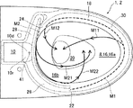
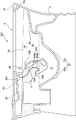
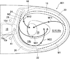
先ず、図1及び図2により、本発明の第1実施形態による水洗式大便器の構成を説明する。図1は、本発明の第1実施形態による水洗式大便器の洗浄水の流れの様子を示す平面図であり、図2は、本発明の第1実施形態による水洗式大便器の左右方向中央での断面図である。
Next, a flush toilet according to an embodiment of the present invention will be described with reference to the accompanying drawings.
First, the configuration of the flush toilet according to the first embodiment of the present invention will be described with reference to FIGS. 1 and 2. FIG. 1 is a plan view showing a flow of washing water in a flush toilet according to the first embodiment of the present invention, and FIG. 2 is a horizontal center of the flush toilet according to the first embodiment of the present invention. FIG.
図1及び図2に示すように、本発明の第1実施形態による水洗式大便器1は、ボウル部8内の水の落差による流水作用で汚物を押し流す洗い落し式便器であり、便器本体2を備えている。便器本体2には、洗浄水源である貯水タンク(図示せず)を介して、洗浄水が導入されるようになっている。便器本体2は、表面に釉薬層が形成された陶器製であり、下部にスカート部6が形成され、上部前方にボウル部8が形成されている。また、ボウル部8の後方には、貯水タンクの排水口に接続される導水路10が形成され、さらに、ボウル部8の後方下部に汚物を排出するための排水路12が形成されている。
As shown in FIGS. 1 and 2, the
もっとも、本発明は、洗浄水源として貯水タンクを使用した水洗式大便器に限らず、洗浄水源としてジェットポンプ機構を使用した貯水タンクを使用して洗浄水を供給する水洗便器や、直接洗浄水が供給される直圧給水式、および、ポンプ給水式の水洗便器等にも適用することができる。 However, the present invention is not limited to a flush toilet using a water storage tank as a wash water source, but a flush toilet that supplies a wash water using a water storage tank using a jet pump mechanism as a wash water source or a direct wash water is used. The present invention can also be applied to supplied direct pressure water supply type and pump water supply type flush toilets.
ボウル部8は、ボウル形状の汚物受け面16と、汚物受け面16の上縁部に形成されたリム部18と、汚物受け面16の下方に形成された凹部20と、を備えている。ここで、本実施形態のリム部18の内周面18aは、図2に示すように、内側に向かってオーバーハングした形状となっており、旋回する洗浄水(詳しくは後述する)が外部へ飛び出ないようになっている。
The
図1に示すように、ボウル部8のリム部18の内周面の前方から見て左側の中央部後方側に、洗浄水を吐水する第1リム吐水口22(リム吐水部)が形成されている。本実施の形態では、更に、前方から見て右側の後方側且つ第1リム吐水口より後方側にも、第2リム吐水口24(リム吐水部)が形成されている。これらの第1リム吐水口22及び第2リム吐水口24は、同一方向(図1では反時計回りの方向)に旋回する旋回流を形成するようになっている。
As shown in FIG. 1, a first rim water discharge port 22 (rim water discharge portion) that discharges cleaning water is formed on the rear side of the central portion on the left side when viewed from the front of the inner peripheral surface of the
また、図1に示すように、ボウル部8の汚物受け面16の後方に形成された導水路10は、第1リム吐水口22に洗浄水を供給する第1リム通水路26(リム通水路)及び第2リム吐水口24に洗浄水を供給する第2リム通水路28(リム通水路)に分岐している。当該分岐領域10dが、リム通水開始領域となっている。
Further, as shown in FIG. 1, a
なお、本実施形態の水洗式大便器1においては、第1リム吐水口22を含む第1リム通水路26と、第2リム吐水口24を含む第2リム通水路28とは、陶器製の便器本体2と一体に形成されている。しかしながら、本発明は、このような形態に限られず、第1リム吐水口を含む第1リム通水路と、第2リム吐水口を含む第2リム通水路とが、便器本体とは別体のディストリビユータ等により形成された形態にも適用可能である。
In the
図1及び図2に示すように、本実施形態による水洗式大便器1のボウル部8の汚物受け面16は、前方側汚物受け面16aと、後方側汚物受け面16bと、を備えている。
As shown in FIGS. 1 and 2, the
そして、図1及び図2に示すように、リム部18の内周面18aの下方領域に、洗浄水を導く棚形通水路30が形成されている。棚形通水路30は、汚物受け面16の外周領域でもある。棚形通水路30は、第1リム吐水口22から吐水された洗浄水がリム部18の内周面18aに沿って旋回することを支援するために設けられており、第1リム吐水口22からボウル部8の前方端に向かって下方に徐々に下降傾斜する一方で、前方端から後方側に向かっては上方へ徐々に上昇傾斜している(図2参照)。また、棚形通水路30は、ボウル部8の後方端では幅狭に形成されている。
And as shown in FIG.1 and FIG.2, the shelf-shaped
このような棚形通水路30の存在のために、第1リム吐水口22から吐水される洗浄水は、図1に示すように、ボウル部8の前方端近傍において棚形通水路30から排水路12に向けて流れ落ち始める主流M11を形成すると共に、棚形通水路30を流れ続けて第2リム吐水口24近傍から排水路12に向けて流れ落ち始める副流M12を形成するようになっている。
Due to the presence of the shelf-shaped
一方、棚形通水路30の後方端が幅狭であるために、第2リム吐水口24から吐水される洗浄水は、ボウル部8の後方端近傍において棚形通水路30から排水路12に向けて流れ落ち始める主流M21を形成すると共に、棚形通水路30を流れ続けて第1リム吐水口22近傍から排水路12に向けて流れ落ち始める副流M22を形成するようになっている。
On the other hand, since the rear end of the shelf-shaped
また、図2に示すように、排水路12は、凹部20の底面と接続し且つ後方下方へ延びる導入管32によって構成されている。導入管32は、トラップ流路を有しており、すなわち、下方へ延びる流路部分32aと、その後に再び上方へ延びる流路部分32bと、を有している。導入管32は、凹部20の底面と滑らかな連続湾曲面として繋がっており、凹部20から導入管32に流入する洗浄水が当該導入管32内をスムーズに流れるようになっている。
Further, as shown in FIG. 2, the
本実施形態では、導水路10の底面(の少なくとも一部)、ボウル部8の後方側汚物受け面16b(の少なくとも一部)、及び、排水路12の上面(の少なくとも一部)は、中実領域S(陶器部分)の外表面によって構成されている。そして、当該中実領域Sに、導水路10の底面から排水路12の上面側に至る水抜流路40が形成されている。
In the present embodiment, the bottom surface (at least part) of the
本実施形態の水抜流路40の出口開口42は、排水路12の上面側の最下位置において開口されている。そして、水抜流路40は出口開口42の近傍領域において、鉛直下向きに延びる。
The
水抜流路40の入口開口41の断面積は、7mm2〜20mm2程度である。但し、水抜流路40の入口開口41を除いた部分(水抜流路40の入口開口41の近傍領域を含む)の断面積は、水抜流路40の入口開口41の断面積よりも大きくなっており、具体的には、20mm2〜80mm2程度である。なお、図1に示すように、本実施形態において入口開口41は円形であるが、本発明はこのような形態に限定されるものではなく、例えば、半円形や四角形等でもよい。
Cross-sectional area of the inlet opening 41 of the
そして、導水路10の底面は、水抜流路40の入口開口41に向けて、高さ位置が低くなっている。具体的には、傾斜角度5°程度で傾斜している。
And the height position of the bottom surface of the
更に、本実施の形態の導水路10の底面は、深さ5mm程度の凹部10rを有しており、水抜流路40の入口開口41は、当該凹部10r内に設けられている。
Furthermore, the bottom surface of the
また、リム通水路26、28の底面は、導水路10の凹部10r(すなわち水抜流路40の入口開口41)に向けて、高さ位置が低くなっている。具体的には、傾斜角度2°程度で傾斜している。
Further, the bottom surfaces of the
次に、以上のような構成からなる本実施形態の作用について説明する。 Next, the operation of the present embodiment configured as described above will be described.
使用者が操作スイッチ(図示せず)をON操作すると、貯水タンクの排水口(図示せず)が開き、所定量の洗浄水が導水路10内に流入する。洗浄水は、導水路10からリム通水開始領域を経て第1リム通水路26及び第2リム通水路28を流れ、第1リム吐水口22及び第2リム吐水口24からそれぞれ吐水される。
When the user turns on an operation switch (not shown), the drainage port (not shown) of the water storage tank opens, and a predetermined amount of cleaning water flows into the
前述のように、第1リム通水路26の底面及び第2リム通水路28の底面には、第1リム吐水口22及び第2リム吐水口24に至る洗浄水の通水を妨げるような傾斜が設けられている。しかし、洗浄水の流入開始時には洗浄水に勢いがあるため、これらの傾斜にも拘わらず、洗浄水は第1リム吐水口22及び第2リム吐水口24を通過して吐水される。
As described above, the bottom surface of the first
本実施形態では、第1リム吐水口22から吐水される洗浄水は、ボウル部8の前方端近傍において棚形通水路30から排水路12に向けて流れ落ち始める主流M11を形成すると共に、棚形通水路30を流れ続けて第2リム吐水口24近傍から排水路12に向けて流れ落ち始める副流M12を形成する。第1リム吐水口22からの主流M11も副流M12も、旋回流となって汚物受け面16を洗浄しながら、排水路12へと排出される。
In the present embodiment, the wash water discharged from the first rim
一方、第2リム吐水口24から吐水される洗浄水は、ボウル部8の後方端近傍において棚形通水路30から排水路12に向けて流れ落ち始める主流M21を形成すると共に、棚形通水路30を流れ続けて第1リム吐水口22近傍から排水路12に向けて流れ落ち始める副流M22を形成する。第2リム吐水口24からの主流M21も副流M22も、旋回流となって汚物受け面16を洗浄しながら、排水路12へと排出される。
On the other hand, the wash water discharged from the
導水路10内に流入した所定量の洗浄水は、ほぼその全てが第1リム吐水口22及び第2リム吐水口24から吐水され、僅かな一部が水抜流路40を介して排水路12に直接排出され、また、僅かな一部が流れに取り残されて導水路10の底面や第1リム通水路26及び第2リム通水路28の底面に留まる。このように留まった残水は、そのまま存置されると、カビなどが生えるという懸念がある。また、リム吐水口22、24から点滴すると、吐水(洗浄)が終了していないとの誤解を与える可能性があると共に、見映えが宜しくなく、また、残水の点滴によりボウル部に水垢が発生する懸念がある。
Almost all of the predetermined amount of washing water that has flowed into the
本実施形態では、そのような問題を解決すべく、導水路10の底面から排水路12の上面側に至る水抜流路40が形成されると共に、導水路10の底面が水抜流路40の入口開口41に向けて、傾斜角度5°程度で傾斜している。このため、導水路10に取り残された残水は、当該傾斜のために水抜流路40の入口開口41へと案内されて水抜される。
In the present embodiment, in order to solve such a problem, a
特に、本実施形態では、導水路10の底面に深さ5mm程度の凹部10rが設けられ、水抜流路40の入口開口41は当該凹部10r内に設けられている。このため、当該凹部10rに集められた残水の水位に応じた水頭圧が作用することで、一層効果的な水抜作用を期待することができる。
In particular, in the present embodiment, a
また、本実施形態では、リム通水路26、28の底面も、導水路10の凹部10r(すなわち水抜流路40の入口開口41)に向けて傾斜角度2°程度で傾斜している。このため、リム通水路26、28に取り残された残水も、当該傾斜のために水抜流路40の入口開口41へと(逆向きに)案内されて水抜される。
In the present embodiment, the bottom surfaces of the
以上のように、本実施形態によれば、リム吐水口22、24から吐出される洗浄水によるボウル部8の洗浄が終了した後(導水路10への所定量の洗浄水の供給が終了した後)、導水路10内に留まりそうになった残水が導水路10の底面の傾斜によって水抜流路40の入口開口41へと案内されて排水路12に排水され、また、リム通水路26、28内に留まりそうになった残水についてもリム通水路26、28の底面の傾斜によって水抜流路40の入口開口41へと(逆向きに)案内されて排水路12に排水されるため、残水がリム通水路26、28を経てリム吐水口22、24から点滴することが効果的に抑制される。
As described above, according to the present embodiment, after the cleaning of the
特に、本実施形態の水抜流路40によれば、汚物受け面16の後方側に位置するリム通水開始領域から排水路12に至るまで、長さが比較的短いため、効果的な水抜作用を期待することができる。
In particular, according to the
また、本実施形態の導水路10は、凹部10rを有しており、水抜流路40の入口開口41は、当該凹部10r内に設けられているため、当該凹部10rに残水が集められるとその水位に応じた水頭圧が作用して、一層効果的な水抜作用を期待することができる。
Moreover, since the
また、本実施の形態の水抜流路40の出口開口42は、排水路12の上面側の最下位置において開口されているため、封水水位が低下して水抜流路40を介して臭気が上がってきてしまうという懸念に対して最も有効である。
In addition, since the outlet opening 42 of the
また、本実施の形態の水抜流路40の入口開口41の断面積は、直径3mm〜5mm程度であるから、ボウル部8の洗浄中に水抜流路40から排水されてしまう洗浄水の量は少なく抑えられている。一方、水抜流路40の入口開口41の近傍領域の断面積が水抜流路40の入口開口41の断面積よりも大きくなっているために、表面張力が作用して残水が水抜流路40の入口開口41に流入しないということも防止されている。
In addition, since the cross-sectional area of the inlet opening 41 of the
なお、水抜流路40の少なくとも一部、例えば入口開口41及びその近傍領域を除く部分は、泥漿を外部に排出するために形成された排泥流路の一部からなることが好ましい。すなわち、陶器として製造される中実領域Sの製造過程で形成される排泥流路の一部を、水抜流路40の少なくとも一部として流用することが好ましい。
In addition, it is preferable that at least a part of the
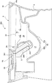
次に、本発明の第2実施形態について、図3を用いて説明する。図3は、本発明の第2実施形態による水洗式大便器201の左右方向中央の断面図である。
Next, a second embodiment of the present invention will be described with reference to FIG. FIG. 3 is a cross-sectional view at the center in the left-right direction of a
図3に示すように、本実施形態の水洗式大便器201においては、水抜流路240の出口開口242が、排水路12の上面側の最下位置よりも後方側において開口されている。そして、水抜流路240の出口開口242の近傍領域の方向が、当該出口開口242に向かって後方向きである。
As shown in FIG. 3, in the
本実施形態の水抜流路240の断面積は、入口開口241及びその近傍領域を含めて、78mm2〜314mm2程度となっている。
Sectional area of the
本実施形態のその他の構成については、図1及び図2を用いて説明した第1実施形態と略同様である。図3において、第1実施形態と同様の部分については、同様の符号を付している。また、本実施形態の第1実施形態と同様の部分については、詳しい説明を省略する。 Other configurations of the present embodiment are substantially the same as those of the first embodiment described with reference to FIGS. 1 and 2. In FIG. 3, the same reference numerals are given to the same parts as those in the first embodiment. Detailed descriptions of the same portions of the present embodiment as those in the first embodiment are omitted.
本実施形態によれば、水抜流路240を通過してくる洗浄水が、封水を後方側(排出側)に向けて押し出すように作用する。この作用は、汚物の排出に効果的である(微弱サイホン)。
According to this embodiment, the washing water passing through the
特に、水抜流路240の断面積が、入口開口241及びその近傍領域を含めて78mm2〜314mm2程度となっていることにより、微弱サイホン効果を十分に発揮することができる。
In particular, the cross-sectional area of the
また、本実施形態によっても、第1実施形態と同様の残水の水抜効果を得ることができる。 Also according to the present embodiment, the same drainage effect as that of the first embodiment can be obtained.
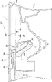
次に、本発明の第3実施形態について、図4を用いて説明する。図4は、本発明の第3実施形態による水洗式大便器301の左右方向中央の断面図である。
Next, a third embodiment of the present invention will be described with reference to FIG. FIG. 4 is a cross-sectional view at the center in the left-right direction of a
図4に示すように、本実施形態の水洗式大便器301においては、水抜流路340の出口開口342が、排水路12の上面側の最下位置よりも前方側において開口されている。但し、美観上の観点から、水抜流路340の出口開口342は、ボウル部8の上方からは見えない位置に設けられている。そして、水抜流路340は出口開口342の近傍領域において、当該出口開口342に向かって後方向きに延びている。
As shown in FIG. 4, in the
本実施形態の水抜流路340の断面積は、入口開口341及びその近傍領域を含めて、78mm2〜314mm2程度となっている。
Sectional area of the
本実施形態のその他の構成については、図1及び図2を用いて説明した第1実施形態と略同様である。図4において、第1実施形態と同様の部分については、同様の符号を付している。また、本実施形態の第1実施形態と同様の部分については、詳しい説明を省略する。 Other configurations of the present embodiment are substantially the same as those of the first embodiment described with reference to FIGS. 1 and 2. In FIG. 4, the same parts as those in the first embodiment are denoted by the same reference numerals. Detailed descriptions of the same portions of the present embodiment as those in the first embodiment are omitted.
本実施形態の場合によっても、水抜流路340を通過してくる洗浄水が、封水を後方側(排出側)に向けて押し出すように作用する。この作用は、汚物の排出に効果的である(微弱サイホン)。
Even in the case of the present embodiment, the washing water passing through the
特に、水抜流路340の断面積が、入口開口341及びその近傍領域を含めて78mm2〜314mm2程度となっていることにより、微弱サイホン効果を十分に発揮することができる。
In particular, the cross-sectional area of the
また、本実施形態によっても、第1実施形態と同様の残水の水抜効果を得ることができる。 Also according to the present embodiment, the same drainage effect as that of the first embodiment can be obtained.
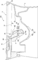
次に、本発明の第4実施形態について、図5を用いて説明する。図5は、本発明の第4実施形態による水洗式大便器401の左右方向中央の断面図である。
Next, a fourth embodiment of the present invention will be described with reference to FIG. FIG. 5 is a cross-sectional view at the center in the left-right direction of a
図5に示すように、本実施形態の水洗式大便器401においては、水抜流路440がトラップ流路444を有している。トラップ流路444は、下方へ延びる流路部分444aの後に再び上方へ延びる流路部分444bを有している。
As shown in FIG. 5, in the
本実施形態のその他の構成については、図1及び図2を用いて説明した第1実施形態と略同様である。図5において、第1実施形態と同様の部分については、同様の符号を付している。また、本実施形態の第1実施形態と同様の部分については、詳しい説明を省略する。 Other configurations of the present embodiment are substantially the same as those of the first embodiment described with reference to FIGS. 1 and 2. In FIG. 5, parts similar to those in the first embodiment are denoted by the same reference numerals. Detailed descriptions of the same portions of the present embodiment as those in the first embodiment are omitted.
本実施形態によれば、水抜流路440がトラップ流路444を有していることにより、水抜流路440の出口開口442に対して封水水面が低下してしまった場合であっても、水抜流路440から排水路12への残水の排出が途切れた後に水抜流路440内に流入する残水によって、いわゆる封水が溜まり、当該封水によって水抜流路440を介して臭気が上がってくることが防止される。
According to the present embodiment, the
また、本実施形態によっても、第1実施形態と同様の残水の水抜効果を得ることができる。 Also according to the present embodiment, the same drainage effect as that of the first embodiment can be obtained.
次に、本発明の第5実施形態について、図6を用いて説明する。図6は、本発明の第5実施形態による水洗式大便器501の左右方向中央の断面図である。
Next, a fifth embodiment of the present invention will be described with reference to FIG. FIG. 6 is a cross-sectional view at the center in the left-right direction of a
図6に示すように、本実施形態の水洗式大便器501においても、水抜流路540がトラップ流路544を有している。トラップ流路544は、下方へ延びる流路部分544aの後に再び上方へ延びる流路部分544bを有している。
As shown in FIG. 6, also in the
しかし、図6に示すように、水抜流路540の出口開口542は、排水路12の上面側の最下位置よりも後方側において開口されており、設計上の封水水面よりも上方に位置づけられている。
However, as shown in FIG. 6, the outlet opening 542 of the
本実施形態のその他の構成については、図1及び図2を用いて説明した第1実施形態と略同様である。図6において、第1実施形態と同様の部分については、同様の符号を付している。また、本実施形態の第1実施形態と同様の部分については、詳しい説明を省略する。 Other configurations of the present embodiment are substantially the same as those of the first embodiment described with reference to FIGS. 1 and 2. In FIG. 6, the same parts as those in the first embodiment are denoted by the same reference numerals. Detailed descriptions of the same portions of the present embodiment as those in the first embodiment are omitted.
本実施形態によれば、水抜流路540がトラップ流路544を有していることにより、水抜流路540の出口開口542よりも封水水面の方が低いにも拘わらず、水抜流路540から排水路12への残水の排出が途切れた後に水抜流路540内に流入する残水によって、いわゆる封水が溜まり、当該封水によって水抜流路を介して臭気が上がってくることが防止される。
According to the present embodiment, the
また、本実施形態によっても、第1実施形態と同様の残水の水抜効果を得ることができる。 Also according to the present embodiment, the same drainage effect as that of the first embodiment can be obtained.
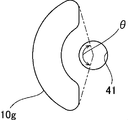
次に、本発明の第6実施形態について、図7乃至図9を用いて説明する。図7は、本発明の第6実施形態による水洗式大便器601の洗浄水の流れの様子を示す平面図であり、図8は、本発明の第6実施形態による水洗式大便器601の左右方向中央の断面図であり、図9は、図7のガイド部10gの拡大平面図である。
Next, a sixth embodiment of the present invention will be described with reference to FIGS. FIG. 7 is a plan view showing a flow of washing water in the
図7乃至図9に示すように、本実施形態の水洗式大便器601においては、上流側から水抜流路40の入口開口41に向かう洗浄水をリム通水路26、28にガイドするガイド部10gが、水抜流路40の入口開口41より上流側の導水路10の底面から突出している。
As shown in FIGS. 7 to 9, in the
具体的には、本実施形態のガイド部10gは、全体として、平面視において円形である入口開口41と同心で左右対称(図7及び図9においては上下対称)の円弧の形状を有する突出部である。
Specifically, the
本実施形態のその他の構成については、図1及び図2を用いて説明した第1実施形態と略同様である。図7乃至図9において、第1実施形態と同様の部分については、同様の符号を付している。また、本実施形態の第1実施形態と同様の部分については、詳しい説明を省略する。 Other configurations of the present embodiment are substantially the same as those of the first embodiment described with reference to FIGS. 1 and 2. 7 to 9, the same reference numerals are given to the same parts as those in the first embodiment. Detailed descriptions of the same portions of the present embodiment as those in the first embodiment are omitted.
本実施形態によっても、第1実施形態と同様の残水の水抜効果を得ることができる。 Also according to the present embodiment, the same drainage effect as that of the first embodiment can be obtained.
そして、本実施形態によれば、全体として円弧状の突出部であるガイド部10gの存在によって、上流側から水抜流路40の入口開口41に向かう洗浄水をリム通水路26、28に円滑にガイドすることができるため、ボウル部の洗浄中において、十分な量の洗浄水をリム吐水口26、28から吐水させることができる。
And according to this embodiment, the washing water which goes to the inlet opening 41 of the
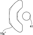
なお、ガイド部10gの形態は、図7乃至図9に示したような円弧状に限定されない。例えば、図10に示すように、平面視で左右対称(図10においては上下対称)のV字状の形態が採用されてもよいし、図11に示すように、両側鏡面が屈曲された三面鏡状の形態が採用されてもよい。
In addition, the form of the
以上の各実施形態は、2つのリム吐水口22、24を有するタイプの水洗式大便器であるが(図1、図7参照)、本発明は1つのみリム吐水口を有するタイプの水洗式大便器や、3つ以上の吐水口を有するタイプの水洗式大便器にも適用可能である。 Each of the above embodiments is a flush toilet bowl having two rim spouts 22 and 24 (see FIGS. 1 and 7), but the present invention is a flush type having only one rim spout. The present invention can also be applied to a toilet bowl or a flush toilet bowl having three or more spouts.
また、以上の各実施形態は、ゼット吐水口を有しないタイプの水洗式大便器であるが、本発明はゼット吐水口を有するタイプのいわゆるサイホンゼット式の水洗式大便器にも適用可能である。 The above embodiments are flush toilets that do not have a jet spout, but the present invention can also be applied to so-called siphon jet flush toilets that have a jet spout. .
1、101、201、301、401、501、601 水洗式大便器
2 便器本体
8 ボウル部
10 導水路
10d 分岐領域
10r 凹部
10g ガイド部
12 排水路
16 汚物受け面
16a 前方側汚物受け面
16b 後方側汚物受け面
18 リム部
18a 内周面
20 凹部
22 第1リム吐水口(リム吐水部)
24 第2リム吐水口(リム吐水部)
26 第1リム通水路(リム通水路)
28 第2リム通水路(リム通水路)
32 導入管
32a 下方へ延びる流路部分
32b 上方へ延びる流路部分
40、240、340、440、540 水抜通路
41、241、341、441、541 入口開口
42、242、342、442、542 出口開口
444、544 水抜流路のトラップ流路
444a、544a 下方へ延びる流路部分
444b、544b 上方へ延びる流路部分
DESCRIPTION OF SYMBOLS 1,101,201,301,401,501,601 Flush toilet bowl 2
24 Second rim spout (rim spout)
26 1st rim waterway (rim waterway)
28 Second Rim Waterway (Rim Waterway)
32
Claims (11)
前記リム部に設けられ、前記ボウル部内に洗浄水を吐水して当該洗浄水による旋回流を形成するリム吐水部と、
前記汚物受け面の後方側に位置するリム通水開始領域まで洗浄水を導水する導水路と、 前記導水路に接続され前記リム通水開始領域から前記リム吐水部まで洗浄水を導水するリム通水路と、
前記ボウル部の下方に接続されトラップ流路を有する排水路と、
前記導水路から前記排水路の上面側に至る水抜流路と、
を備えたことを特徴とする水洗式大便器。 A bowl portion having a bowl-shaped waste receiving surface, and a rim portion formed on the upper edge of the waste receiving surface;
A rim water spouting portion provided in the rim portion, for discharging washing water into the bowl portion to form a swirling flow by the washing water;
A water conduit that guides cleaning water to a rim water flow start area located on the rear side of the waste receiving surface; Waterways,
A drainage channel connected below the bowl portion and having a trap channel;
A drainage channel from the water conduit to the upper surface side of the drainage channel;
A flush toilet characterized by comprising
ことを特徴とする請求項1に記載の水洗式大便器。 The flush toilet according to claim 1, wherein a height position of the bottom surface of the water conduit is lowered toward an inlet opening of the drainage channel.
前記水抜流路の入口開口は、前記凹部内に設けられている
ことを特徴とする請求項1または2に記載の水洗式大便器。 The water conduit has a recess,
The flush toilet according to claim 1 or 2, wherein an inlet opening of the drainage channel is provided in the recess.
ことを特徴とする請求項1乃至3のいずれかに記載の水洗式大便器。 The flush-type large according to any one of claims 1 to 3, wherein the bottom surface of the rim water passage has a lower height position toward an inlet opening of the water conduit or the drainage channel. Toilet bowl.
ことを特徴とする請求項1乃至4のいずれかに記載の水洗式大便器。 The flush toilet according to any one of claims 1 to 4, wherein an outlet opening of the drainage channel is opened at a lowermost position on an upper surface side of the drainage channel.
前記水抜流路が当該出口開口の近傍領域で延びる方向は、当該出口開口に向かって後方向きである
ことを特徴とする請求項1乃至4のいずれかに記載の水洗式大便器。 The outlet opening of the drainage channel is opened on the rear side from the lowest position on the upper surface side of the drainage channel,
The flush toilet according to any one of claims 1 to 4, wherein a direction in which the drainage channel extends in a region near the outlet opening is rearward toward the outlet opening.
前記水抜流路が当該出口開口の近傍領域で延びる、当該出口開口に向かって後方向きである
ことを特徴とする請求項1乃至4のいずれかに記載の水洗式大便器。 The outlet opening of the drainage channel is opened on the front side from the lowest position on the upper surface side of the drainage channel,
The flush toilet according to any one of claims 1 to 4, wherein the drainage channel extends rearward toward the outlet opening and extends in a region near the outlet opening.
ことを特徴とする請求項1乃至7のいずれかに記載の水洗式大便器。 The flush toilet according to any one of claims 1 to 7, wherein the drainage channel has a trap channel.
ことを特徴とする請求項1乃至8のいずれかに記載の水洗式大便器。 The water conduit has a guide portion that protrudes from the bottom surface of the water conduit on the upstream side from the inlet opening of the water drainage channel and guides cleaning water from the upstream side toward the inlet opening of the water drainage channel to the rim water conduit. A flush toilet according to any one of claims 1 to 8.
ことを特徴とする請求項1乃至9のいずれかに記載の水洗式大便器。 The flush toilet according to any one of claims 1 to 9, wherein a cross-sectional area of a region near an inlet opening of the drainage channel is larger than a cross-sectional area of the inlet opening of the drainage channel.
ことを特徴とする請求項1乃至10のいずれかに記載の水洗式大便器。 The flush toilet according to any one of claims 1 to 10, wherein at least a part of the drainage channel is a part of a mud channel formed to discharge mud to the outside. .
Priority Applications (1)
| Application Number | Priority Date | Filing Date | Title |
|---|---|---|---|
| JP2021180124A JP7337330B2 (en) | 2016-03-14 | 2021-11-04 | flush toilet |
Applications Claiming Priority (2)
| Application Number | Priority Date | Filing Date | Title |
|---|---|---|---|
| JP2016050194 | 2016-03-14 | ||
| JP2016050194 | 2016-03-14 |
Related Child Applications (1)
| Application Number | Title | Priority Date | Filing Date |
|---|---|---|---|
| JP2021180124A Division JP7337330B2 (en) | 2016-03-14 | 2021-11-04 | flush toilet |
Publications (2)
| Publication Number | Publication Date |
|---|---|
| JP2017166315A true JP2017166315A (en) | 2017-09-21 |
| JP6972496B2 JP6972496B2 (en) | 2021-11-24 |
Family
ID=59913134
Family Applications (4)
| Application Number | Title | Priority Date | Filing Date |
|---|---|---|---|
| JP2017048898A Active JP6972496B2 (en) | 2016-03-14 | 2017-03-14 | Flush toilet |
| JP2021180124A Active JP7337330B2 (en) | 2016-03-14 | 2021-11-04 | flush toilet |
| JP2023080037A Active JP7511817B2 (en) | 2016-03-14 | 2023-05-15 | Flush toilet |
| JP2024102634A Pending JP2024117827A (en) | 2016-03-14 | 2024-06-26 | Flush toilet |
Family Applications After (3)
| Application Number | Title | Priority Date | Filing Date |
|---|---|---|---|
| JP2021180124A Active JP7337330B2 (en) | 2016-03-14 | 2021-11-04 | flush toilet |
| JP2023080037A Active JP7511817B2 (en) | 2016-03-14 | 2023-05-15 | Flush toilet |
| JP2024102634A Pending JP2024117827A (en) | 2016-03-14 | 2024-06-26 | Flush toilet |
Country Status (1)
| Country | Link |
|---|---|
| JP (4) | JP6972496B2 (en) |
Cited By (8)
| Publication number | Priority date | Publication date | Assignee | Title |
|---|---|---|---|---|
| CN110939183A (en) * | 2018-09-25 | 2020-03-31 | Toto株式会社 | Flush toilet |
| JP2020051048A (en) * | 2018-09-25 | 2020-04-02 | Toto株式会社 | Water closet |
| CN112575863A (en) * | 2019-09-30 | 2021-03-30 | Toto株式会社 | Flush toilet |
| JP2021127564A (en) * | 2020-02-10 | 2021-09-02 | Toto株式会社 | Water closet |
| JP2023125545A (en) * | 2022-02-28 | 2023-09-07 | Toto株式会社 | Flush toilet bowl |
| WO2023184774A1 (en) * | 2022-03-28 | 2023-10-05 | 箭牌家居集团股份有限公司 | Sewage discharging system of hanging toilet, and hanging toilet |
| WO2023184772A1 (en) * | 2022-03-28 | 2023-10-05 | 箭牌家居集团股份有限公司 | Waterfall-type washing hanging toilet |
| US12421708B2 (en) | 2022-02-28 | 2025-09-23 | Toto Ltd. | Flush toilet |
Families Citing this family (1)
| Publication number | Priority date | Publication date | Assignee | Title |
|---|---|---|---|---|
| JP7766868B2 (en) * | 2023-09-21 | 2025-11-11 | Toto株式会社 | flush toilet |
Citations (11)
| Publication number | Priority date | Publication date | Assignee | Title |
|---|---|---|---|---|
| JPH0657979U (en) * | 1992-12-04 | 1994-08-12 | 東陶機器株式会社 | Flush toilet |
| WO1999057385A1 (en) * | 1998-05-06 | 1999-11-11 | Keramik Holding Ag Laufen | W.c. bowl |
| JP2007169935A (en) * | 2005-12-20 | 2007-07-05 | Matsushita Electric Works Ltd | Water closet |
| WO2009050985A1 (en) * | 2007-10-15 | 2009-04-23 | Toto Ltd. | Flush toilet |
| DE202010003446U1 (en) * | 2010-03-11 | 2011-04-21 | Zuknik, Jürgen | Closure for the entrance of a drainage pipe |
| JP2014037723A (en) * | 2012-08-17 | 2014-02-27 | Lixil Corp | Toilet bowl body and siphon type flush toilet bowl comprises this |
| JP2015194004A (en) * | 2014-03-31 | 2015-11-05 | 株式会社Lixil | Toilet bowl body |
| JP2015196960A (en) * | 2014-03-31 | 2015-11-09 | Toto株式会社 | Flush toilet |
| JP2015536392A (en) * | 2012-10-23 | 2015-12-21 | スタック, パトリック ジェラルドSTACK, Patrick Gerard | Overflow prevention toilet and its manufacturing method |
| US20160024774A1 (en) * | 2014-07-28 | 2016-01-28 | Patrick Gerard Stack | Anti-overflow toilet with detachable primary and secondary drain tubes |
| JP2016089542A (en) * | 2014-11-07 | 2016-05-23 | 株式会社Lixil | Toilet body |
Family Cites Families (1)
| Publication number | Priority date | Publication date | Assignee | Title |
|---|---|---|---|---|
| JP1532604S (en) * | 2014-08-20 | 2015-09-07 |
-
2017
- 2017-03-14 JP JP2017048898A patent/JP6972496B2/en active Active
-
2021
- 2021-11-04 JP JP2021180124A patent/JP7337330B2/en active Active
-
2023
- 2023-05-15 JP JP2023080037A patent/JP7511817B2/en active Active
-
2024
- 2024-06-26 JP JP2024102634A patent/JP2024117827A/en active Pending
Patent Citations (11)
| Publication number | Priority date | Publication date | Assignee | Title |
|---|---|---|---|---|
| JPH0657979U (en) * | 1992-12-04 | 1994-08-12 | 東陶機器株式会社 | Flush toilet |
| WO1999057385A1 (en) * | 1998-05-06 | 1999-11-11 | Keramik Holding Ag Laufen | W.c. bowl |
| JP2007169935A (en) * | 2005-12-20 | 2007-07-05 | Matsushita Electric Works Ltd | Water closet |
| WO2009050985A1 (en) * | 2007-10-15 | 2009-04-23 | Toto Ltd. | Flush toilet |
| DE202010003446U1 (en) * | 2010-03-11 | 2011-04-21 | Zuknik, Jürgen | Closure for the entrance of a drainage pipe |
| JP2014037723A (en) * | 2012-08-17 | 2014-02-27 | Lixil Corp | Toilet bowl body and siphon type flush toilet bowl comprises this |
| JP2015536392A (en) * | 2012-10-23 | 2015-12-21 | スタック, パトリック ジェラルドSTACK, Patrick Gerard | Overflow prevention toilet and its manufacturing method |
| JP2015194004A (en) * | 2014-03-31 | 2015-11-05 | 株式会社Lixil | Toilet bowl body |
| JP2015196960A (en) * | 2014-03-31 | 2015-11-09 | Toto株式会社 | Flush toilet |
| US20160024774A1 (en) * | 2014-07-28 | 2016-01-28 | Patrick Gerard Stack | Anti-overflow toilet with detachable primary and secondary drain tubes |
| JP2016089542A (en) * | 2014-11-07 | 2016-05-23 | 株式会社Lixil | Toilet body |
Cited By (15)
| Publication number | Priority date | Publication date | Assignee | Title |
|---|---|---|---|---|
| CN110939183B (en) * | 2018-09-25 | 2021-04-27 | Toto株式会社 | Flush toilet |
| JP2020051048A (en) * | 2018-09-25 | 2020-04-02 | Toto株式会社 | Water closet |
| US11124955B2 (en) | 2018-09-25 | 2021-09-21 | Toto Ltd. | Flush toilet |
| CN110939183A (en) * | 2018-09-25 | 2020-03-31 | Toto株式会社 | Flush toilet |
| JP2021055437A (en) * | 2019-09-30 | 2021-04-08 | Toto株式会社 | Water closet |
| CN112575863A (en) * | 2019-09-30 | 2021-03-30 | Toto株式会社 | Flush toilet |
| JP7624798B2 (en) | 2019-09-30 | 2025-01-31 | Toto株式会社 | Flush toilet |
| JP2021127564A (en) * | 2020-02-10 | 2021-09-02 | Toto株式会社 | Water closet |
| JP7434983B2 (en) | 2020-02-10 | 2024-02-21 | Toto株式会社 | flush toilet |
| JP2023125545A (en) * | 2022-02-28 | 2023-09-07 | Toto株式会社 | Flush toilet bowl |
| JP7409409B2 (en) | 2022-02-28 | 2024-01-09 | Toto株式会社 | flush toilet |
| JP2024019622A (en) * | 2022-02-28 | 2024-02-09 | Toto株式会社 | flush toilet |
| US12421708B2 (en) | 2022-02-28 | 2025-09-23 | Toto Ltd. | Flush toilet |
| WO2023184774A1 (en) * | 2022-03-28 | 2023-10-05 | 箭牌家居集团股份有限公司 | Sewage discharging system of hanging toilet, and hanging toilet |
| WO2023184772A1 (en) * | 2022-03-28 | 2023-10-05 | 箭牌家居集团股份有限公司 | Waterfall-type washing hanging toilet |
Also Published As
| Publication number | Publication date |
|---|---|
| JP2022009996A (en) | 2022-01-14 |
| JP7511817B2 (en) | 2024-07-08 |
| JP7337330B2 (en) | 2023-09-04 |
| JP2024117827A (en) | 2024-08-29 |
| JP2023099648A (en) | 2023-07-13 |
| JP6972496B2 (en) | 2021-11-24 |
Similar Documents
| Publication | Publication Date | Title |
|---|---|---|
| JP7337330B2 (en) | flush toilet | |
| JP5093627B1 (en) | Flush toilet | |
| JP6472591B2 (en) | Flush toilet | |
| JP6573065B2 (en) | Flush toilet | |
| JP2015067954A (en) | Water closet bowl | |
| JP2015190245A (en) | Water closet | |
| JP6238012B2 (en) | Flush toilet | |
| JP2013170396A (en) | Water closet | |
| JP2015068164A (en) | Water closet bowl | |
| JP7205797B2 (en) | flush toilet | |
| JP2017172119A (en) | Flush toilet bowl | |
| JP2013050027A (en) | Water closet | |
| JP2020051052A (en) | Water closet | |
| JP2019173305A (en) | Toilet bowl | |
| JP5158454B2 (en) | Flush toilet | |
| CN219992634U (en) | Squatting pan | |
| JP2001026960A (en) | Flush toilet stool | |
| JP6579499B2 (en) | Flush toilet | |
| JP2021113496A (en) | Flush toilet bowl | |
| JP2012237126A (en) | Flush toilet bowl | |
| JP2021120536A (en) | Flush toilet bowl | |
| JP2017115551A (en) | Flush toilet bowl | |
| JP7584003B2 (en) | Flush toilet | |
| JP6718587B2 (en) | Flush toilet | |
| JP2019203380A (en) | Flush toilet bowl |
Legal Events
| Date | Code | Title | Description |
|---|---|---|---|
| A621 | Written request for application examination |
Free format text: JAPANESE INTERMEDIATE CODE: A621 Effective date: 20200109 |
|
| A977 | Report on retrieval |
Free format text: JAPANESE INTERMEDIATE CODE: A971007 Effective date: 20201130 |
|
| A131 | Notification of reasons for refusal |
Free format text: JAPANESE INTERMEDIATE CODE: A131 Effective date: 20201203 |
|
| A521 | Request for written amendment filed |
Free format text: JAPANESE INTERMEDIATE CODE: A523 Effective date: 20210129 |
|
| A131 | Notification of reasons for refusal |
Free format text: JAPANESE INTERMEDIATE CODE: A131 Effective date: 20210527 |
|
| A521 | Request for written amendment filed |
Free format text: JAPANESE INTERMEDIATE CODE: A523 Effective date: 20210720 |
|
| TRDD | Decision of grant or rejection written | ||
| A01 | Written decision to grant a patent or to grant a registration (utility model) |
Free format text: JAPANESE INTERMEDIATE CODE: A01 Effective date: 20211004 |
|
| A61 | First payment of annual fees (during grant procedure) |
Free format text: JAPANESE INTERMEDIATE CODE: A61 Effective date: 20211017 |
|
| R150 | Certificate of patent or registration of utility model |
Ref document number: 6972496 Country of ref document: JP Free format text: JAPANESE INTERMEDIATE CODE: R150 |