JP2017164260A - Ozone sterilization method and ozone sterilization device - Google Patents
Ozone sterilization method and ozone sterilization device Download PDFInfo
- Publication number
- JP2017164260A JP2017164260A JP2016051900A JP2016051900A JP2017164260A JP 2017164260 A JP2017164260 A JP 2017164260A JP 2016051900 A JP2016051900 A JP 2016051900A JP 2016051900 A JP2016051900 A JP 2016051900A JP 2017164260 A JP2017164260 A JP 2017164260A
- Authority
- JP
- Japan
- Prior art keywords
- chamber
- ozone gas
- ozone
- water
- sterilization
- Prior art date
- Legal status (The legal status is an assumption and is not a legal conclusion. Google has not performed a legal analysis and makes no representation as to the accuracy of the status listed.)
- Granted
Links
Images


Abstract
Description
本発明は、飲料や食品の製造設備等の環境の殺菌にオゾンガスを用いる方法および装置に関する。 The present invention relates to a method and apparatus for using ozone gas to sterilize an environment such as a beverage or food production facility.
無菌環境下で清涼飲料等を容器に充填する無菌充填システムでは、薬剤や熱水等、殺菌可能な媒体を用いて容器および環境の殺菌が行われている(例えば、特許文献1)。
殺菌可能な媒体としては、オゾン(O3)ガスも知られている。
In an aseptic filling system that fills a container with a soft drink or the like in an aseptic environment, the container and the environment are sterilized using a sterilizable medium such as a medicine or hot water (for example, Patent Document 1).
As a sterilizable medium, ozone (O 3 ) gas is also known.
オゾンガスは、殺菌剤等と比べて温度管理やリンス等の観点から取り扱いが容易であり、また、強力な酸化力により、殻を持つ芽胞菌等をも殺菌できるので、オゾンガスによる衛生環境の殺菌を実用化したい。
そこで、本発明は、オゾンガスを使用し、殺菌が必要な環境を対象として、実用化に足りる殺菌能力を得ることのできる殺菌方法および殺菌装置を提供することを目的とする。
Ozone gas is easier to handle in terms of temperature control and rinsing than sterilizers, and because of its strong oxidizing power, it can sterilize spore bacteria with shells. I want to put it to practical use.
Therefore, an object of the present invention is to provide a sterilization method and a sterilization apparatus that can obtain a sterilization ability sufficient for practical use in an environment that uses ozone gas and requires sterilization.
本発明のオゾン殺菌方法は、殺菌が必要な環境を区画するチャンバの内側にオゾンガスを供給するオゾンガス供給ステップと、チャンバの内側に水を散布する水散布ステップと、オゾンガスおよび水のミストが存在するチャンバ内の雰囲気を循環させる循環ステップと、を含むことを特徴とする。 The ozone sterilization method of the present invention includes an ozone gas supply step for supplying ozone gas to the inside of a chamber that partitions an environment that requires sterilization, a water spraying step for spraying water inside the chamber, and a mist of ozone gas and water. And a circulation step for circulating the atmosphere in the chamber.
本発明のオゾン殺菌方法では、水散布ステップが開始された直後から、循環ステップを行うことが好ましい。 In the ozone sterilization method of the present invention, the circulation step is preferably performed immediately after the water spraying step is started.
本発明のオゾン殺菌方法におけるオゾンガス供給ステップでは、オゾンガスを加湿して得られた湿潤オゾンガスをチャンバの内側に供給することが好ましい。 In the ozone gas supply step in the ozone sterilization method of the present invention, it is preferable to supply wet ozone gas obtained by humidifying ozone gas to the inside of the chamber.
また、本発明のオゾン殺菌方法は、オゾンを含有し、かつ加湿されている湿潤オゾンガスを、殺菌が必要な環境を区画するチャンバの内側に供給するオゾンガス供給ステップと、湿潤オゾンガスが存在するチャンバ内の雰囲気を循環させる循環ステップと、を含むことを特徴とする。 The ozone sterilization method of the present invention includes an ozone gas supply step for supplying wet ozone gas containing and humidified to the inside of a chamber that partitions an environment that requires sterilization, and in the chamber in which the wet ozone gas exists. And a circulation step for circulating the atmosphere.
本発明のオゾン殺菌方法におけるオゾンガス供給ステップでは、チャンバ内の雰囲気のオゾンガス濃度が、体積%濃度で0.5%以上となるまでオゾンガスまたは湿潤オゾンガスをチャンバの内側に供給することが好ましい。 In the ozone gas supply step in the ozone sterilization method of the present invention, it is preferable to supply ozone gas or wet ozone gas to the inside of the chamber until the ozone gas concentration in the atmosphere in the chamber becomes 0.5% or more by volume% concentration.
本発明のオゾンガス殺菌方法は、循環ステップを含む第1殺菌ステップと、60℃以上に加温された温水をチャンバの内側に散布する第2殺菌ステップと、を有することが好ましい。 The ozone gas sterilization method of the present invention preferably includes a first sterilization step including a circulation step, and a second sterilization step of spraying warm water heated to 60 ° C. or more inside the chamber.
本発明のオゾンガス殺菌装置は、殺菌が必要な環境を区画するチャンバと、オゾンを含有するオゾンガスをチャンバの内側に供給するオゾンガス供給装置と、水をチャンバの内側に散布する水散布装置と、チャンバ内の雰囲気に、チャンバ内を循環する循環流を発生させる循環手段と、を備えることを特徴とする。 An ozone gas sterilizer according to the present invention includes a chamber for partitioning an environment that requires sterilization, an ozone gas supply device that supplies ozone gas containing ozone to the inside of the chamber, a water spray device that sprays water to the inside of the chamber, and a chamber Circulating means for generating a circulating flow circulating in the chamber is provided in the inner atmosphere.
本発明におけるオゾンガス供給装置は、オゾンガスを加湿して得られた湿潤オゾンガスをチャンバの内側に供給することが好ましい。 The ozone gas supply device in the present invention preferably supplies wet ozone gas obtained by humidifying ozone gas to the inside of the chamber.
また、本発明のオゾン殺菌装置は、殺菌が必要な環境を区画するチャンバと、オゾンを含有し、かつ加湿されている湿潤オゾンガスをチャンバの内側に供給する湿潤オゾンガス供給装置と、チャンバ内の雰囲気に、チャンバ内を循環する循環流を発生させる循環手段と、を備えることを特徴とする。 The ozone sterilization apparatus of the present invention includes a chamber for partitioning an environment that requires sterilization, a wet ozone gas supply device that supplies wet ozone gas that contains ozone and is humidified, and an atmosphere in the chamber. And a circulation means for generating a circulation flow circulating in the chamber.
本発明の無菌充填機は、上述のオゾン殺菌装置と、チャンバ内で容器に内容物を充填する充填装置と、を備えることを特徴とする。 An aseptic filling machine according to the present invention includes the above-described ozone sterilization apparatus and a filling apparatus that fills a container with contents in a chamber.
本発明によれば、オゾンガスとミスト状の水とを別々にチャンバ内に供給する、あるいは、湿潤オゾンガスをチャンバ内に供給し、チャンバ内の雰囲気を循環させることにより、チャンバ内に供給されたオゾンガスに含まれるO3を最大限に利用し、実用化に足りる殺菌能力を得ることができる。 According to the present invention, ozone gas and mist-like water are separately supplied into the chamber, or ozone gas supplied into the chamber is supplied by supplying wet ozone gas into the chamber and circulating the atmosphere in the chamber. the O 3 contained in the full advantage can be obtained sterilizing effect sufficient to practical use.
以下、添付図面を参照しながら、本発明の実施形態について説明する。
以下で説明する各実施形態では、本発明の殺菌装置を備えた無菌充填機を例に取り、説明する。
〔第1実施形態〕
まず、図1を参照し、無菌充填機1の構成を簡単に説明する。
無菌充填機1は、図示しない容器を搬送しながら洗浄・殺菌し、清涼飲料等の飲料を容器に充填した後、容器の口部を閉塞する。
無菌充填機1による処理は、大気に対して陽圧としたチャンバ2内で行われる。
無菌充填機1は、チャンバ2と、チャンバ2内に配置された殺菌装置15と、充填装置11と、キャッパ12とを備えている。殺菌装置15,充填装置11およびキャッパ12と、コンベヤ13,14および複数の回転体16等とを含んで、容器の搬送装置が構成されている。チャンバ2内は、図示しない隔壁により、殺菌装置15が配置される第1区画と、充填装置11およびキャッパ12が配置される第2区画とに区分されており、異物混入防止のため、第1区画内の圧力に対して第2区画内の圧力を高くしている。
なお、搬送装置の構成は、図示したものに限らず、適宜に構成することができる。
Hereinafter, embodiments of the present invention will be described with reference to the accompanying drawings.
In each embodiment described below, an aseptic filling machine including the sterilization apparatus of the present invention will be described as an example.
[First Embodiment]
First, the configuration of the
The
Processing by the
The
In addition, the structure of a conveying apparatus is not restricted to what was illustrated, It can comprise suitably.
容器の構成は特に限定されない。容器は、例えば、PET(Polyethyleneterephthalate)等の樹脂材料から形成されたボトルや、アルミニウム合金等の金属材料から形成されたボトル缶である。 The configuration of the container is not particularly limited. The container is, for example, a bottle formed from a resin material such as PET (Polyethyleneterephthalate) or a bottle can formed from a metal material such as an aluminum alloy.
チャンバ2は、飲料を充填するにあたり、殺菌により衛生を確保する必要のある環境1Eを区画している。
無菌充填機1は、環境1Eつまりチャンバ2の内側を殺菌するオゾン殺菌装置10を含んで構成されている。環境1Eは、オゾン殺菌装置10により、所定の頻度で殺菌される。
オゾン殺菌装置10による殺菌対象は、例えば、殺菌装置15、充填装置11、キャッパ12、コンベヤ13,14、回転体16等を構成する部材や、チャンバ2の内壁2W、チャンバ2内のフロア、そしてチャンバ2の内部空間である。つまり、チャンバ2内に配置される部材や、チャンバ2自体、そしてチャンバ2内の気体を含め、チャンバ2の内部の全体が、オゾン殺菌装置10により殺菌される。そうして無菌化されたチャンバ2内で、無菌充填機1は、容器を搬送しつつ、例えば、薬剤や熱水を用いて、あるいはオゾンガスを用いて容器を殺菌し、清浄な容器の内部に飲料(内容物)を充填する。
The
The
The objects to be sterilized by the
本実施形態は、オゾン(O3)ガスおよび水のミストがチャンバ2内に存在する状態で、チャンバ2内の雰囲気2Aに流動を与えてチャンバ2内を循環させることを特徴としている。
以下、チャンバ2内の環境1Eを殺菌するオゾン殺菌装置10の構成について説明する。
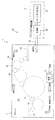
オゾン殺菌装置10(図1)は、上述したチャンバ2と、オゾンガス供給装置3と、水ミスト供給装置4(水散布装置)と、循環ファン5と、温水散布装置6とを備えている。
The present embodiment is characterized in that in a state where ozone (O 3 ) gas and water mist exist in the
Hereinafter, the configuration of the
The ozone sterilizer 10 (FIG. 1) includes the
オゾンガス供給装置3は、オゾンを含有するオゾンガスをチャンバ2内に供給する。オゾンガス供給装置3は、オゾンガス生成器31と、生成されたオゾンガスをチャンバ2内に供給する供給部32とを備えている。オゾンガスは空気よりも重いため、供給部32を通じて上方からチャンバ2内に供給されることが好ましい。
オゾンガス生成器31は、酸素(O2)ガスを原料として、酸素ガスの一部がオゾン(O3)ガスに置換されたガスを生成する。原料ガスとして、酸素を含む他のガス、例えば空気を用いることも可能である。
The ozone
The
本明細書において、「オゾンガス」は、オゾン(O3)ガスと、酸素(O2)ガス等の他のガスとが混合したガスのことも含むものとする。かかる混合ガスにおけるオゾン濃度は、典型的には、体積%濃度で10%〜20%程度である。 In this specification, the “ozone gas” includes a gas in which ozone (O 3 ) gas and other gas such as oxygen (O 2 ) gas are mixed. The ozone concentration in such a mixed gas is typically about 10% to 20% in volume% concentration.
オゾン生成の方式には無声放電方式、電気分解方式、紫外線ランプ方式等がある。工業的用途には無声放電方式が用いられており、無声放電方式を適用することが好ましいが、他の方式を採用することを妨げない。ここで、無声放電(Silent discharge)とは、平行電極間に誘電体(dielectric)を設け、この間に酸素ガスを供給し、両極間に交流高電圧を印加する際に観察される放電現象である。この無声放電により気体中に電子eが放出される。この電子eを安定な酸素分子O2に衝突させて、酸素分子O2を酸素原子Oに解離させるステップ(1)と、酸素原子O、酸素分子O2、および第三の物質M(例えば、窒素分子)を含めた三体衝突が生ずるステップ(2)とにより、オゾンが生成される。オゾンガスには、第三の物質も含まれる。
ステップ(1) O2+e→2O+e
ステップ(2) O+O2+M→O3+M
また、必要に応じてPSA法(Pressure Swing Adsorption: 圧力スイング法)によるオゾン濃縮が併用されることもある。
There are a silent discharge method, an electrolysis method, an ultraviolet lamp method, and the like as a method for generating ozone. The silent discharge method is used for industrial applications, and it is preferable to apply the silent discharge method, but it does not prevent other methods from being adopted. Here, silent discharge is a discharge phenomenon observed when a dielectric is provided between parallel electrodes, oxygen gas is supplied therebetween, and an alternating high voltage is applied between the two electrodes. . Electrons e are emitted into the gas by this silent discharge. A step (1) of causing the electrons e to collide with a stable oxygen molecule O 2 to dissociate the oxygen molecule O 2 into an oxygen atom O, an oxygen atom O, an oxygen molecule O 2 , and a third substance M (for example, Ozone is generated by the step (2) in which a three-body collision including nitrogen molecules occurs. The ozone gas includes a third substance.
Step (1) O2 + e → 2O + e
Step (2) O + O2 + M → O3 + M
Moreover, ozone concentration by PSA method (Pressure Swing Adsorption: pressure swing method) may be used together as needed.
水ミスト供給装置4は、水道等の水供給源に接続されたノズル41を含んで構成されており、ノズル41を通じてチャンバ2内に水を散布する。ノズル41の小さな開口からは霧状の水(水ミスト)が噴霧される。
公知の適宜な方法により水をミスト化することができる。例えば、ポンプや圧縮空気等により水を圧送してノズル41からミストを噴霧することができる。あるいは、高速の空気流を利用して水を吸い上げて霧状にするジェット式や、超音波を水に照射することで水を霧状にする超音波式によっても、ノズル41から水のミストを噴霧することができる。
The water
Water can be misted by a known appropriate method. For example, mist can be sprayed from the
少なくとも1つの水ミスト供給装置4がオゾン殺菌装置10に備えられていれば足りるが、2以上の水ミスト供給装置4がオゾン殺菌装置10に備えられていてもよい。例えば、破線で示す位置にも、水ミスト供給装置4を設けることができる。
It is sufficient if at least one water
オゾンガスは、水(H2O)を介して菌(有機物)と化学反応することで殺菌作用を発揮する。
環境1Eの殺菌にオゾンガスと共に用いる水としては、一般の上水道からの常温の水を用いることができる。水は、安価であり、排液処理も必要ない。
水を介した反応に伴って強い殺菌力が得られるので、水自体に殺菌力は必要ないが、加温した水、あるいは過酸化水素(H2O2)や過酢酸(CH3COOOH)等の薬剤を加えた酸性水を用いることも、殺菌能力を上積みする等の目的から許容される。水を加温すると、反応が促進されて殺菌力が向上する。酸性水には、オゾン濃度を安定させる効果がある。
本明細書において、「水」には、温水や、酸性水も含まれる。
Ozone gas exhibits a bactericidal action by chemically reacting with bacteria (organic matter) via water (H 2 O).
As water used with ozone gas for the sterilization of
Since strong sterilizing power is obtained with the reaction via water, water itself does not need sterilizing power, but heated water, hydrogen peroxide (H 2 O 2 ), peracetic acid (CH 3 COOOH), etc. The use of acidic water to which the above chemicals are added is also permitted for the purpose of increasing the sterilizing ability. When water is heated, the reaction is promoted and the sterilizing power is improved. Acidic water has the effect of stabilizing the ozone concentration.
In the present specification, “water” includes warm water and acidic water.
循環ファン5は、チャンバ2内の雰囲気2Aに、チャンバ2内を循環する循環流FCを発生させる。ここでは、チャンバ2の内部に循環ファン5が設置されている。循環ファン5のブレードの回転に伴い、チャンバ2内のガスが循環ファン5に吸い込まれつつ、循環ファン5から送り出されることにより、チャンバ2内でガスが循環される。
ここで、「循環」は、自然対流を含まず、強制的な流れをチャンバ2内の雰囲気2Aの全体に与えてチャンバ2内を循環させることをいうものとする。
循環ファン5として、遠心ファンや軸流ファン等の適宜な送風機、あるいはブロワを用いることができる。
また、無菌エアを無菌チャンバ2内に供給するためにチャンバ2の天井等に設置されているファンフィルターユニットの外気取り込み経路をダンパー等で閉じ、内気循環に変更することで、循環ファン5に代替することも可能である。
The
Here, “circulation” refers to circulation in the
As the
In addition, in order to supply aseptic air into the
温水散布装置6は、60℃以上に加温された温水をチャンバ2内に散布する。この温水散布装置6は、無菌水を貯留するタンク等の無菌水供給源61と、無菌水を加温するヒータ62と、加温された無菌温水(以下、単に温水)を圧送するポンプ63と、温水をチャンバ2内に散布するスプリンクラ64とを備えている。スプリンクラ64は、チャンバ2内に設置された装置よりも上方からノズル64Aにより温水を散布する。
なお、温水散布装置6が、スプリンクラ64に代えて、チャンバ2内に温水を噴射するノズルを備えて構成されていてもよい。
The hot
The hot
本実施形態では、以下で説明する方法により、容器に飲料が充填される環境1Eを殺菌する。
まず、図2(a)に示すように、オゾンガス供給装置3により、チャンバ2内にオゾンガスを吹き込み、チャンバ2内にオゾンガスを充満させる(オゾンガス供給ステップS11)。チャンバ2内の雰囲気2Aのオゾンガス濃度が、体積%濃度で0.5%以上となるまで、チャンバ2内にオゾンガスを供給することが好ましい。環境1Eの殺菌に許容される殺菌時間も考慮する必要があるが、殺菌能力を高める観点からは、できるだけ高い濃度のオゾンガスをチャンバ2内に充満させることが好ましい。
In the present embodiment, the
First, as shown in FIG. 2A, ozone gas is blown into the
オゾンガス供給ステップS11では循環ファン5を停止していてもよいが、循環ファン5を作動させてチャンバ2内の雰囲気2Aを循環させると、チャンバ2内のオゾンガスの濃度が均一化されるので好ましい。
In the ozone gas supply step S11, the
オゾンガス供給ステップS11に続いて、あるいは並行して、図2(b)に示すように、水ミスト供給装置4によりチャンバ2内に水を散布しながら、循環ファン5を作動させてチャンバ2内の雰囲気2Aを循環させる(水散布ステップS12および循環ステップS13)。このとき、チャンバ2内には、オゾンガスおよび水ミストが存在している。そのチャンバ2内の雰囲気2Aには、チャンバ2内で循環する循環流FCが形成される。
Following or in parallel with the ozone gas supply step S11, as shown in FIG. 2 (b), the water
チャンバ2内に水が散布されると、チャンバ2内の装置の部材等に水が付着するほか、チャンバ2内の循環流FCに水ミストが巻き込まれながら流動する。水は、自重により、いずれチャンバ2内の装置の部材やフロアに滴下するものの、水のミストが循環流FCに巻き込まれて雰囲気2A中を流動している間に、後述するように高い殺菌効果を得ることができる。
When water is sprayed in the
水ミスト供給装置4のノズル41から噴霧された水ミストは、循環流FCに乗ってチャンバ2内の全体に拡散される。ノズル41から噴霧された霧粒が細かい程、少ない水によりチャンバ2内の全体に亘り濡らすことができる。例えば、チャンバ2の内壁2Wの表面積の1平米あたり0.1〜10L(リットル)の量の水をノズル41から噴霧することにより、チャンバ2の内壁2Wや、チャンバ2内に設置された装置の部材の全体を満遍なく水で濡らすことができる。水ミストの粒径は、例えば、数μm〜数十μmである。
散布される水の量は、より好ましくは、0.5〜2.0L/m2である。例示した水の量は、チャンバ2内に散布される水の合計の量であり、2つの水ミスト供給装置4が用いられる場合は、各水ミスト供給装置4により、例えば、半量ずつ散布される。
The water mist sprayed from the
The amount of water sprayed is more preferably 0.5 to 2.0 L / m 2 . The amount of water illustrated is the total amount of water sprayed into the
水散布ステップS12および循環ステップS13において、チャンバ2内には、オゾンガスと水との気液界面が随所に形成される。
ここでいう「気液界面」は、例えば、チャンバ2の内壁2Wに付着した水と、周囲のオゾンガスとの界面に相当する。また、循環流FCに巻き込まれながら移動する水ミストの表面に存在する気液界面にも相当する。本明細書において、「気液界面」は、これらの気液界面を包含している。
オゾンガスと水とが接触している気液界面において、オゾンガスが水を介して有機物と反応し、その反応時に生成されるヒドロキシラジカル等のラジカルが発現する酸化力によって有機物が分解される。この酸化力は強力であって、芽胞菌等の殻を持つ菌をも、その殻を破壊して死滅させることができる。
In the water spraying step S12 and the circulation step S13, a gas-liquid interface between ozone gas and water is formed in the
Here, the “gas-liquid interface” corresponds to, for example, an interface between water adhering to the
At the gas-liquid interface where the ozone gas and water are in contact, the ozone gas reacts with the organic substance via the water, and the organic substance is decomposed by the oxidizing power that expresses radicals such as hydroxy radicals generated during the reaction. This oxidizing power is strong, and even a bacterium having a shell such as a spore bacterium can be destroyed by killing the shell.
ここで、オゾンガスを用いることにより得られる殺菌能力は、オゾンガスの濃度にも依存する。チャンバ2内のオゾンガス濃度は、上述したように例えば、体積%濃度で0.5%であり、高いとは言えない。したがって、環境1Eの殺菌に要求される、例えば5分〜20分間程度の時間内で、チャンバ2内の随所にオゾンガスと水との気液界面を形成し、その気液界面と有機物とが接触する機会を多くすることが、殺菌能力の向上に寄与する。
本実施形態では、オゾンガスおよび水ミストが存在するチャンバ2内の雰囲気2Aを所定時間だけ循環させることに伴う殺菌作用により、チャンバ2内の全体に亘り十分に殺菌することができる。
Here, the sterilization ability obtained by using ozone gas also depends on the concentration of ozone gas. As described above, the ozone gas concentration in the
In the present embodiment, the entire interior of the
以上で述べたステップS11〜S13により、オゾンガスおよび水を用いる第1殺菌ステップS1が完了する。
続いて、図2(c)に示すように、温水の散布により殺菌する第2殺菌ステップS2(温水散布ステップ)を行う。この第2殺菌ステップS2では、主としてカビを殺菌対象としている。
第2殺菌ステップS2では、温水散布装置6により、60℃以上の温水をスプリンクラ64を通じてチャンバ2の天井から下方に向けて散布する。温水は、スプリンクラ64の複数のノズル64Aから、チャンバ2内の全体に散布される。
カビを含め、第1殺菌ステップS1の後に残存していた菌は、温水の熱により死滅する。
殺菌能力をより十分に確保するため、65℃以上の温水をノズル64Aから10秒間以上噴射することで、その間、チャンバ2内の全体を60℃以上に保つことが好ましい。
第2殺菌ステップS2では、循環ファン5を停止していてもよいが、循環ファン5を作動させていると、チャンバ2内の雰囲気温度の上昇を促進させることができる。
By the steps S11 to S13 described above, the first sterilization step S1 using ozone gas and water is completed.
Then, as shown in FIG.2 (c), 2nd sterilization step S2 (warm water spraying step) sterilized by spraying warm water is performed. In the second sterilization step S2, mold is mainly targeted for sterilization.
In the second sterilization step S <b> 2, the hot
The bacteria remaining after the first sterilization step S1 including mold are killed by the heat of hot water.
In order to ensure sufficient sterilization capability, it is preferable to keep the entire interior of the
In the second sterilization step S2, the
温水の散布により、チャンバ2の内部が洗い流される。つまり、第2殺菌ステップS2は、第1殺菌ステップS1による残留物のリンスも兼ねている。
温水散布による殺菌およびリンスを確実に行う観点から、例えば、50〜200L/m2程度の温水を散布することが好ましい。
The inside of the
From the viewpoint of reliably performing sterilization and rinsing by hot water spraying, for example, it is preferable to spray hot water of about 50 to 200 L / m 2 .
以上により、環境1Eの殺菌が完了する。オゾンは活性種であるため、チャンバ2内のオゾンガスはいずれ酸素ガスへと変化して安定する。オゾンガスは、例えば、活性炭等を通すことにより容易に無害化することができるので、排出処理が容易である。
Thus, the sterilization of the
さて、図3を参照し、オゾンガスおよび水ミストが供給されたチャンバ2内で循環流FCが形成されることによる作用を説明する。
図3(a)〜(c)は、それぞれ、チャンバ2内の部材の表面7に付着したり雰囲気2A中に存在する水W1,W2と、チャンバ2内の雰囲気2Aに含まれるオゾン(O3)ガスとの或る一瞬を捉えたものである。部材の表面7に、菌(有機物)が存在するものとして説明する。
オゾンガスと水W1とが接触している気液界面100(図3(a))において、オゾンガスが水W1を介して有機物と反応する。そのとき、ヒドロキシラジカル等のラジカルを放出し、オゾンガスおよび有機物の分解を伴いながら、反応が進行する。
Now, with reference to FIG. 3, the operation of the circulation flow FC formed in the
3A to 3C show water W1 and W2 that adhere to the
At the gas-liquid interface 100 (FIG. 3A) where the ozone gas and the water W1 are in contact, the ozone gas reacts with the organic substance via the water W1. At that time, radicals such as hydroxy radicals are released, and the reaction proceeds while decomposing ozone gas and organic matter.
ここで、仮に、チャンバ2内の雰囲気2Aが流動しておらず、有機物との反応により生成された酸素等のガス(図3(a)に「O2」と図示)がその場に留まると、その場に存在する有機物の分解がそれ以上には進行しない。
しかし、本実施形態では、図3(a)および(b)に示すように、チャンバ2内の循環流FCにより、反応後のガス(O2)がその場から流れ去り、それに伴い、新たにオゾンガス(O3)が流入する。つまり、有機物との反応によりオゾンガスが消費されても、循環流FCにより、次から次へとオゾンガスが供給されるので、有機物を確実に分解することができる。
Here, if the
However, in this embodiment, as shown in FIGS. 3A and 3B, the gas (O 2 ) after reaction flows away from the site by the circulating flow FC in the
水を介したオゾンガスと有機物との反応は、チャンバ2内の循環流FCの中でも起こっている。循環流FCに巻き込まれている水ミストW2の表面は、オゾンガスと水との気液界面100に相当する。循環流FCは、オゾンガスに無数の水ミストW2を巻き込みながら流れているので、チャンバ2の内部空間や、チャンバ2内に配置された部材の表面7に存在する有機物がオゾンガスおよび水ミストW2に接触して分解される。循環流FCにおいて、水ミストW2は周囲のオゾンガスに対して相対的に変位するように流れており、循環流FCに巻き込まれている水ミストW2にも、図3(a)および(b)に示す水W1と同様に、次々と新たなオゾンガスが供給されるので、殺菌を効率よく行える。
上記のように循環流FCに巻き込まれつつ流動する水ミストW2により、殺菌効果を高めることができる。殺菌効果を高める観点より、水散布ステップS12の開始直後から循環ファン5を作動させて循環流FCを形成することが好ましい。
The reaction between the ozone gas and the organic matter via water occurs also in the circulating flow FC in the
The sterilizing effect can be enhanced by the water mist W2 that flows while being entrained in the circulating flow FC as described above. From the viewpoint of enhancing the sterilizing effect, it is preferable to operate the
図3(c)は、水散布ステップS12が開始された直後に、水ミストW2が部材の表面7に付着している様子を示している。水の散布が開始された直後であるため、部材の表面7には、水ミストW2が互いに分離した状態で存在している。このように水ミストW2が表面7に付着していると、その後に、表面7に別の水ミストW2が降り掛かり水ミストW2同士が結合して作られる水溜まりに比べて、気液界面100の表面積が大きい。しかも、水ミストW2の周囲が雰囲気2Aに開放されているので、水ミストW2とオゾンガスとの気液界面100で有機物との反応により生成されたガスがその場からスムーズに流出し、新たなオゾンガスに置き換わる。以上で述べた観点からも、殺菌を効率よく行える。
水ミストW2が互いに分離した状態で部材の表面7に存在するとき、つまり、水散布ステップS12が開始された直後は、それ以降と比べてチャンバ2内のオゾンガスの濃度が高い。オゾンガスの濃度が高い、水散布ステップS12の開始直後において殺菌効果が高いことは、殺菌能力向上への貢献度が高い。
FIG. 3C shows a state in which the water mist W2 is attached to the
When the water mist W2 is present on the
上記より示唆されているが、水散布ステップS12を開始する前には、チャンバ2内に水が散布されておらず、部材の表面7が濡れていないことが好ましい。先にチャンバ2内に散布された水が部材の表面7に滞留しているとすれば、オゾンガスは水に溶け難いので、オゾンガスが有機物にアクセスするにあたり、水が障壁となって、それ以上にオゾンガスと有機物との反応が起こり難い。そのため、スプリンクラ64により温水を散布する第2殺菌ステップS2は、水散布ステップS12および循環ステップS13よりも後に行う必要がある。
As suggested above, it is preferable that water is not sprayed in the
図3(a)〜(c)を参照して説明した現象が複合的に生じることにより、チャンバ2内の全体として、オゾンガスと有機物とが継続して反応しており、チャンバ2内の全体に亘って殺菌が行われることとなる。
したがって、チャンバ2内のオゾンガスの濃度が低いとしても、所定の殺菌時間内に十分に殺菌することができる。
As the phenomenon described with reference to FIGS. 3A to 3C occurs in combination, the ozone gas and the organic substance continuously react as a whole in the
Therefore, even if the ozone gas concentration in the
ところで、オゾンガスおよび水を用いて殺菌対象を殺菌する方法としては、他に、オゾンガスの微小気泡を溶存させた水、あるいは電気分解により水に含まれる酸素を利用して作られたオゾン水をスプリンクラ等によりチャンバ2内に噴射する方法も考えられる。しかし、その方法により得られる水中のオゾンガス濃度は低いので、それらの水を大量に使用したとしても、十分な殺菌能力を得ることが難しい。オゾンガスの微小気泡を溶存させた水やオゾン水のオゾンガス濃度は、濃度を高めるために低温環境にて生成した場合でも、体積%濃度で数mg/L〜数十mg/Lであり、それらの水を大量に使用したとしても、十分な殺菌能力を得ることが難しく、コストも高くつく。
By the way, as a method for sterilizing an object to be sterilized using ozone gas and water, other than that, water in which microbubbles of ozone gas are dissolved, or ozone water made by utilizing oxygen contained in water by electrolysis is used. A method of injecting into the
以上で説明した本実施形態によれば、オゾンガスおよび水のミストを別々にチャンバ2内に供給し、チャンバ2内の雰囲気2Aに循環流FCを形成することにより、チャンバ2内に供給されたオゾンガスに含まれるO3を最大限に利用して高い殺菌能力を得ることができる。本実施形態の殺菌方法によれば、要求される殺菌時間内に、生存菌を1/106に減少させるレベル6Dの殺菌能力を実現することができる。オゾンガス供給ステップS11により0.5%以上の体積%濃度となるまでオゾンガスをチャンバ2内に供給して上述のように殺菌を行うことにより、オゾンガスを補充しないでレベル6Dの殺菌能力が得られることが確認されている。
本実施形態の殺菌方法に用いる水およびオゾンガスは、薬剤や熱水等を用いる場合と比べて、処理や装置のコストが安価であり、容器に匂いが残留しない。
According to the present embodiment described above, ozone gas and water mist are separately supplied into the
The water and ozone gas used in the sterilization method of the present embodiment are cheaper in treatment and apparatus than in the case of using chemicals or hot water, and no odor remains in the container.
〔第2実施形態〕
次に、図4を参照し、本発明の第2実施形態について説明する。
以下、第1実施形態と相違する事項を中心に説明する。
第2実施形態では、オゾンガスおよび水を用いる殺菌方法による殺菌能力をさらに高めるため、加湿されたオゾンガスを用いる。
[Second Embodiment]
Next, a second embodiment of the present invention will be described with reference to FIG.
In the following, the description will be focused on matters that are different from the first embodiment.
In the second embodiment, humidified ozone gas is used in order to further enhance the sterilization ability by the sterilization method using ozone gas and water.
第2実施形態のオゾン殺菌装置10は、図4に示すように、チャンバ2と、加湿機能を有するオゾンガス供給装置3と、水ミスト供給装置4と、循環ファン5とを備えている。
オゾンガス供給装置3(湿潤オゾンガス供給装置)は、オゾンガス生成器31と、生成されたオゾンガスを加湿する加湿部33と、供給部32とを備えている。
加湿部33は、オゾンガス生成器31により生成されたオゾンガスに水を含ませることで、意図的に湿度が高められた湿潤オゾンガスを得る。湿潤オゾンガスの湿度は、例えば、90%以上である。湿潤オゾンガスが供給部32によりチャンバ2内に供給される。
As shown in FIG. 4, the
The ozone gas supply device 3 (wet ozone gas supply device) includes an
The
適宜な方法によりオゾンガスを加湿することができる。加湿方法の例としては、水中にオゾンガスをバブリングさせる気泡溶解法、別々に生成された湿潤ガス(酸素等)とオゾンガスとを混合する混合法、シャワー状に散布される水にオゾンガスを供給するシャワー法等を挙げることができる。 The ozone gas can be humidified by an appropriate method. Examples of humidification methods include a bubble dissolution method in which ozone gas is bubbled into water, a mixing method in which separately generated wet gas (oxygen, etc.) and ozone gas are mixed, and a shower that supplies ozone gas to water sprayed in a shower form The law etc. can be mentioned.
図5を参照し、環境1Eを殺菌する第2実施形態の殺菌方法について説明する。
まず、オゾンガス供給装置3により、湿潤オゾンガスをチャンバ2内に供給する(湿潤オゾンガス供給ステップS31)。第1実施形態と同様に、オゾンガス濃度が0.5%以上となるように湿潤オゾンガスをチャンバ2内に充満させることが好ましい。また、循環ファン5を作動させ、オゾンガス濃度の均一化を図ることも好ましい。
With reference to FIG. 5, the sterilization method of 2nd Embodiment which sterilizes
First, wet ozone gas is supplied into the
ステップS31に続いて、あるいは並行して、水ミスト供給装置4によりチャンバ2内に水を散布するとともに、循環ファン5を作動させる(水散布ステップS12および循環ステップS13)。ステップS12,S13の間に、オゾンガスと水とがチャンバ2内の随所で形成する気液界面100(図3)において有機物が分解される。
Following or in parallel with step S31, water is sprayed into the
さらに、第2実施形態では、次の殺菌作用が得られる。
チャンバ2内には、水ミスト供給装置4により散布される水に加えて、湿潤オゾンガス中の水分も存在するので、チャンバ2内の雰囲気2A中の水分量が第1実施形態におけるチャンバ2内の水分量よりも多い。湿潤オゾンガス中に含まれる水蒸気とオゾンガスとに有機物が接触することにより、殺菌が行われる。チャンバ2内の循環流FCにおいて、湿潤オゾンガス中の水蒸気とオゾンガスとが相対的に流動することで、水蒸気の周囲のオゾンガスが次々に入れ替わるので、オゾンガスと有機物との反応が停滞せずに継続して行われる。
第2実施形態によれば、湿潤オゾンガスに含まれる水蒸気の分だけ、殺菌能力を高めることができる。
Furthermore, in the second embodiment, the following bactericidal action is obtained.
In the
According to the second embodiment, the sterilizing ability can be increased by the amount of water vapor contained in the wet ozone gas.
参考として、ある一点空間に、体積%濃度で10%のオゾンガスを10L/minの流量で供給し、バブリングによる加湿有無をパラメータとして実施した殺菌試験結果を下記の表に示す。殺菌対象は、Bacillus atrophaeusであり、殺菌時間は60秒である。 As a reference, the following table shows the results of a sterilization test conducted by supplying ozone gas of 10% in volume% concentration at a flow rate of 10 L / min to a certain point space and using the presence or absence of humidification by bubbling as a parameter. The sterilization target is Bacillus atrophaeus, and the sterilization time is 60 seconds.

LRV(Logarithmic Reduction Value)は、菌の対数減少値であり、LRV「1」は,10個の菌を1個に減少させる殺菌性能を意味する。
上記の表より、オゾンガスを加湿すると、殺菌性能(能力)が向上する。
LRV (Logarithmic Reduction Value) is a logarithmic reduction value of bacteria, and LRV “1” means sterilization performance that reduces 10 bacteria to one.
From the above table, when the ozone gas is humidified, the sterilization performance (ability) is improved.
第2実施形態によれば、カビについても、6Dの殺菌能力を実現できる。
したがって、第2実施形態では、第2殺菌ステップS2としての温水散布が必要ない。そのため、無菌水や加温に要するコストを抑えることができる。また、温水散布が必要ない分、殺菌時間を短縮したり、あるいは、省略した温水散布の時間の分だけ、オゾンガスおよび水を用いる殺菌ステップに時間を掛けて、殺菌能力を高めることができる。
According to the second embodiment, 6D sterilization ability can be realized even for mold.
Therefore, in the second embodiment, it is not necessary to spray hot water as the second sterilization step S2. Therefore, the cost required for aseptic water and heating can be suppressed. In addition, the sterilization time can be shortened by the amount that the hot water spraying is not required, or the sterilization ability using the ozone gas and water can be increased by the time for the omitted hot water spraying time, thereby improving the sterilization ability.
なお、第2実施形態においても、第2殺菌ステップS2として温水散布を行うことを妨げるものではない。ステップS31とステップS12,S13に続いて、あるいは並行して、上述した温水散布装置6によりチャンバ2内に温水を散布することも許容される。
Note that, in the second embodiment as well, the hot water spraying is not prevented as the second sterilization step S2. After step S31 and steps S12 and S13, or in parallel, it is allowed to spray hot water into the
〔第3実施形態〕
図6は、本発明の第3実施形態を示している。
第3実施形態では、チャンバ2内に湿潤オゾンガスを供給する。チャンバ2内には水を散布しないことが第2実施形態とは相違する。
第3実施形態のオゾン殺菌装置10は、図6に示すように、チャンバ2と、加湿機能を有するオゾンガス供給装置3と、循環ファン5とを備えている。
チャンバ2内に湿潤オゾンガスを充満させ、湿潤オゾンガスが存在するチャンバ2内の雰囲気2Aに循環流FCを形成する。そうすることで、湿潤オゾンガスに含まれる水分に対して、その水分の周囲のオゾンガスが相対的に流動するので、水を介したオゾンガスと有機物との反応が停滞せずに進行する。循環流FCにより湿潤オゾンガスがチャンバ2内の隅々にまで行き渡るので、チャンバ2の内部の全体に亘り、湿潤オゾンガスが接触した部材の表面等が殺菌される。
[Third Embodiment]
FIG. 6 shows a third embodiment of the present invention.
In the third embodiment, wet ozone gas is supplied into the
The
The
上記以外にも、本発明の主旨を逸脱しない限り、上記実施形態で挙げた構成を取捨選択したり、他の構成に適宜変更することが可能である。
図7に示す例のように、チャンバ2に接続されたダクト8の一端から、ダクト8内に配置されたファン9によってチャンバ2内のガスの一部をダクト8内に吸い出し、ダクト8の他端からチャンバ2内にガスを送り込むことにより、チャンバ2内の雰囲気が循環するように構成することもできる。この場合、ダクト8およびファン9が循環手段に相当する。
In addition to the above, as long as the gist of the present invention is not deviated, the configuration described in the above embodiment can be selected or changed to another configuration as appropriate.
As shown in the example shown in FIG. 7, a part of the gas in the
チャンバ2内に供給したオゾンガスを回収し、環境1Eや容器の殺菌にリサイクルすることにより、コストダウンすることができる。
Costs can be reduced by collecting the ozone gas supplied into the
1 無菌充填機
1E 環境
2 チャンバ
2A 雰囲気
2W 内壁
3 オゾンガス供給装置
4 水ミスト供給装置(水散布装置)
5 循環ファン(循環手段)
6 温水散布装置
7 表面
8 ダクト
9 ファン
10 オゾン殺菌装置
11 充填装置
12 キャッパ
13,14 コンベヤ
15 殺菌装置
16 回転体
31 オゾンガス生成器
32 供給部
33 加湿部
41 ノズル
61 無菌水供給源
62 ヒータ
63 ポンプ
64 スプリンクラ
64A ノズル
100 気液界面
FC 循環流
S1 第1殺菌ステップ
S2 第2殺菌ステップ
S11 オゾンガス供給ステップ
S12 水散布ステップ
S13 循環ステップ
S31 湿潤オゾンガス供給ステップ
W1 水
W2 水ミスト
1
5 Circulation fan (circulation means)
6 Hot
Claims (10)
前記チャンバの内側に水を散布する水散布ステップと、
前記オゾンガスおよび前記水のミストが存在する前記チャンバ内の雰囲気を循環させる循環ステップと、を含む、
ことを特徴とするオゾン殺菌方法。 An ozone gas supply step for supplying ozone gas to the inside of a chamber that partitions an environment that requires sterilization;
A water spraying step for spraying water inside the chamber;
Circulating the atmosphere in the chamber in which the ozone gas and the mist of water are present.
The ozone sterilization method characterized by the above-mentioned.
ことを特徴とする請求項1に記載のオゾン殺菌方法。 Immediately after the water spraying step is started, the circulation step is performed.
The ozone sterilization method according to claim 1.
前記オゾンガスを加湿して得られた湿潤オゾンガスを前記チャンバの内側に供給する、
ことを特徴とする請求項1または2に記載のオゾン殺菌方法。 In the ozone gas supply step,
Supplying wet ozone gas obtained by humidifying the ozone gas to the inside of the chamber;
The ozone sterilization method according to claim 1 or 2.
前記湿潤オゾンガスが存在する前記チャンバ内の雰囲気を循環させる循環ステップと、を含む、
ことを特徴とするオゾン殺菌方法。 An ozone gas supply step for supplying wet ozone gas containing ozone and being humidified to the inside of a chamber defining an environment requiring sterilization;
Circulating the atmosphere in the chamber in which the wet ozone gas exists.
The ozone sterilization method characterized by the above-mentioned.
前記チャンバ内の雰囲気のオゾンガス濃度が、体積%濃度で0.5%以上となるまで前記オゾンガスまたは前記湿潤オゾンガスを前記チャンバの内側に供給する、
ことを特徴とする請求項1から4のいずれか一項に記載のオゾン殺菌方法。 In the ozone gas supply step,
The ozone gas or the wet ozone gas is supplied to the inside of the chamber until the ozone gas concentration of the atmosphere in the chamber becomes 0.5% or more by volume% concentration.
The ozone sterilization method according to any one of claims 1 to 4, wherein
60℃以上に加温された温水を前記チャンバの内側に散布する第2殺菌ステップと、を有する、
ことを特徴とする請求項1から5のいずれか一項に記載のオゾン殺菌方法。 A first sterilization step including the circulation step;
A second sterilization step of spraying hot water heated to 60 ° C. or more inside the chamber,
The ozone sterilization method according to any one of claims 1 to 5, wherein:
オゾンを含有するオゾンガスを前記チャンバの内側に供給するオゾンガス供給装置と、
水を前記チャンバの内側に散布する水散布装置と、
前記チャンバ内の雰囲気に、前記チャンバ内を循環する循環流を発生させる循環手段と、を備える、
ことを特徴とするオゾン殺菌装置。 A chamber that defines an environment that requires sterilization;
An ozone gas supply device for supplying ozone gas containing ozone to the inside of the chamber;
A water spraying device for spraying water inside the chamber;
A circulation means for generating a circulation flow circulating in the chamber in the atmosphere in the chamber;
An ozone sterilizer characterized by that.
前記オゾンガスを加湿して得られた湿潤オゾンガスを前記チャンバの内側に供給する、
ことを特徴とする請求項7に記載のオゾン殺菌装置。 The ozone gas supply device
Supplying wet ozone gas obtained by humidifying the ozone gas to the inside of the chamber;
The ozone sterilizer according to claim 7.
オゾンを含有し、かつ加湿されている湿潤オゾンガスを前記チャンバの内側に供給する湿潤オゾンガス供給装置と、
前記チャンバ内の雰囲気に、前記チャンバ内を循環する循環流を発生させる循環手段と、を備える、
ことを特徴とするオゾン殺菌装置。 A chamber that defines an environment that requires sterilization;
A wet ozone gas supply device that supplies wet ozone gas that contains ozone and is humidified to the inside of the chamber;
A circulation means for generating a circulation flow circulating in the chamber in the atmosphere in the chamber;
An ozone sterilizer characterized by that.
前記チャンバ内で容器に内容物を充填する充填装置と、を備える、
ことを特徴とする無菌充填機。 The ozone sterilizer according to any one of claims 7 to 9,
A filling device for filling the container with the contents in the chamber,
Aseptic filling machine characterized by that.
Priority Applications (1)
| Application Number | Priority Date | Filing Date | Title |
|---|---|---|---|
| JP2016051900A JP6769719B2 (en) | 2016-03-16 | 2016-03-16 | Ozone sterilization method |
Applications Claiming Priority (1)
| Application Number | Priority Date | Filing Date | Title |
|---|---|---|---|
| JP2016051900A JP6769719B2 (en) | 2016-03-16 | 2016-03-16 | Ozone sterilization method |
Publications (2)
| Publication Number | Publication Date |
|---|---|
| JP2017164260A true JP2017164260A (en) | 2017-09-21 |
| JP6769719B2 JP6769719B2 (en) | 2020-10-14 |
Family
ID=59908526
Family Applications (1)
| Application Number | Title | Priority Date | Filing Date |
|---|---|---|---|
| JP2016051900A Active JP6769719B2 (en) | 2016-03-16 | 2016-03-16 | Ozone sterilization method |
Country Status (1)
| Country | Link |
|---|---|
| JP (1) | JP6769719B2 (en) |
Cited By (2)
| Publication number | Priority date | Publication date | Assignee | Title |
|---|---|---|---|---|
| WO2022049984A1 (en) | 2020-09-07 | 2022-03-10 | ウシオ電機株式会社 | Sterilization treatment method and sterilization treatment device |
| WO2022075451A1 (en) | 2020-10-09 | 2022-04-14 | 株式会社エースネット | Antipathogenic drug, antibacterial agent, antiviral agent, pathogen processing device, method for producing antipathogenic drug, antibacterial method, virus inactivation method, and pathogen processing method |
Citations (9)
| Publication number | Priority date | Publication date | Assignee | Title |
|---|---|---|---|---|
| JPS61176352A (en) * | 1985-01-30 | 1986-08-08 | エスキル リ−ナント カ−ルソン | Sterilizing method and apparatus |
| JPH0780052A (en) * | 1993-09-20 | 1995-03-28 | Dai Ichi Seiyaku Co Ltd | Ozone sterilizing device and ozone sterilizing method |
| JPH11267189A (en) * | 1998-03-24 | 1999-10-05 | Iwatani Internatl Corp | Sterilizing method using ozone gas |
| JP2000140077A (en) * | 1998-11-16 | 2000-05-23 | Ishikawajima Harima Heavy Ind Co Ltd | Microbe sterilizer |
| JP2004130006A (en) * | 2002-10-15 | 2004-04-30 | Fuji Electric Systems Co Ltd | Ozone sterilization method, and its apparatus |
| US20060130498A1 (en) * | 2004-12-20 | 2006-06-22 | General Electric Company | System and method for preserving food |
| JP2007506484A (en) * | 2003-09-26 | 2007-03-22 | ティー・エス・オー・スリー・インコーポレイテッド | Improved ozone sterilization method |
| JP2010259648A (en) * | 2009-05-08 | 2010-11-18 | Tso3 Inc | Ozone sterilization method and device thereof |
| JP2014080207A (en) * | 2012-10-16 | 2014-05-08 | Mitsubishi Heavy Industries Food & Packaging Machinery Co Ltd | Sterilization method of container and aseptic beverage filling system |
-
2016
- 2016-03-16 JP JP2016051900A patent/JP6769719B2/en active Active
Patent Citations (9)
| Publication number | Priority date | Publication date | Assignee | Title |
|---|---|---|---|---|
| JPS61176352A (en) * | 1985-01-30 | 1986-08-08 | エスキル リ−ナント カ−ルソン | Sterilizing method and apparatus |
| JPH0780052A (en) * | 1993-09-20 | 1995-03-28 | Dai Ichi Seiyaku Co Ltd | Ozone sterilizing device and ozone sterilizing method |
| JPH11267189A (en) * | 1998-03-24 | 1999-10-05 | Iwatani Internatl Corp | Sterilizing method using ozone gas |
| JP2000140077A (en) * | 1998-11-16 | 2000-05-23 | Ishikawajima Harima Heavy Ind Co Ltd | Microbe sterilizer |
| JP2004130006A (en) * | 2002-10-15 | 2004-04-30 | Fuji Electric Systems Co Ltd | Ozone sterilization method, and its apparatus |
| JP2007506484A (en) * | 2003-09-26 | 2007-03-22 | ティー・エス・オー・スリー・インコーポレイテッド | Improved ozone sterilization method |
| US20060130498A1 (en) * | 2004-12-20 | 2006-06-22 | General Electric Company | System and method for preserving food |
| JP2010259648A (en) * | 2009-05-08 | 2010-11-18 | Tso3 Inc | Ozone sterilization method and device thereof |
| JP2014080207A (en) * | 2012-10-16 | 2014-05-08 | Mitsubishi Heavy Industries Food & Packaging Machinery Co Ltd | Sterilization method of container and aseptic beverage filling system |
Cited By (2)
| Publication number | Priority date | Publication date | Assignee | Title |
|---|---|---|---|---|
| WO2022049984A1 (en) | 2020-09-07 | 2022-03-10 | ウシオ電機株式会社 | Sterilization treatment method and sterilization treatment device |
| WO2022075451A1 (en) | 2020-10-09 | 2022-04-14 | 株式会社エースネット | Antipathogenic drug, antibacterial agent, antiviral agent, pathogen processing device, method for producing antipathogenic drug, antibacterial method, virus inactivation method, and pathogen processing method |
Also Published As
| Publication number | Publication date |
|---|---|
| JP6769719B2 (en) | 2020-10-14 |
Similar Documents
| Publication | Publication Date | Title |
|---|---|---|
| KR102214680B1 (en) | Apparatus for generating activated cleaning fluid | |
| CN107073147B (en) | Hydrogen peroxide plasma ionization generating device with double nozzles | |
| JP5441285B1 (en) | Chlorine dioxide gas generator and medical instrument sterilization box | |
| JP2016185828A (en) | Sterilization method and sterilization apparatus for container | |
| JP6704448B2 (en) | Sterilizer | |
| JP6309444B2 (en) | Sterilization method | |
| JP2010119829A (en) | Air cleaner | |
| JP2003169842A (en) | Sterilizing method and sterilizing apparatus by aqueous hypochlorous acid solution | |
| JP5575863B2 (en) | Portable washer | |
| JP6769719B2 (en) | Ozone sterilization method | |
| EP2667903A1 (en) | Cleansing system using ozone and nebulized fluids | |
| KR101924620B1 (en) | Hydrogen peroxide aerosol equipment with air blower | |
| JP5808030B1 (en) | Air purifier | |
| JP2007006956A (en) | Air cleaner having bactericidal and deodorization function | |
| KR101910152B1 (en) | Hydrogen peroxide aerosol equipment with humidity responsive injection control unit | |
| JP2015192621A (en) | Sterilizing component removal device, disinfection device, disinfected environment maintaining system, and sterilizing component removal method | |
| KR101899898B1 (en) | Sterilization and deodorization equipment using hypochlorous acid gas, sterilization and deodorization method thereof | |
| JP2016040508A (en) | Humidifier using platinum shield technology | |
| JP2010233910A (en) | Deodorizing apparatus | |
| TW200702001A (en) | Fan type anion/ozone mist disinfector | |
| JP2018000398A (en) | Sterilization device | |
| JP2022036815A (en) | Disinfectant generator and disinfectant generation method | |
| JP2009115440A (en) | Centrifugal type humidifier | |
| KR200286647Y1 (en) | Cleaning device using a apparatus for generating ozonized water | |
| KR102479272B1 (en) | Disinfection system using plasma discharge water and spray nozzle spraying plasma discharge water as droplet |
Legal Events
| Date | Code | Title | Description |
|---|---|---|---|
| A711 | Notification of change in applicant |
Free format text: JAPANESE INTERMEDIATE CODE: A712 Effective date: 20170317 |
|
| A625 | Written request for application examination (by other person) |
Free format text: JAPANESE INTERMEDIATE CODE: A625 Effective date: 20190227 |
|
| A977 | Report on retrieval |
Free format text: JAPANESE INTERMEDIATE CODE: A971007 Effective date: 20191210 |
|
| A131 | Notification of reasons for refusal |
Free format text: JAPANESE INTERMEDIATE CODE: A131 Effective date: 20200107 |
|
| A521 | Request for written amendment filed |
Free format text: JAPANESE INTERMEDIATE CODE: A523 Effective date: 20200227 |
|
| A131 | Notification of reasons for refusal |
Free format text: JAPANESE INTERMEDIATE CODE: A131 Effective date: 20200428 |
|
| A521 | Request for written amendment filed |
Free format text: JAPANESE INTERMEDIATE CODE: A523 Effective date: 20200611 |
|
| TRDD | Decision of grant or rejection written | ||
| A01 | Written decision to grant a patent or to grant a registration (utility model) |
Free format text: JAPANESE INTERMEDIATE CODE: A01 Effective date: 20200901 |
|
| A61 | First payment of annual fees (during grant procedure) |
Free format text: JAPANESE INTERMEDIATE CODE: A61 Effective date: 20200924 |
|
| R150 | Certificate of patent or registration of utility model |
Ref document number: 6769719 Country of ref document: JP Free format text: JAPANESE INTERMEDIATE CODE: R150 |