JP2017163708A - Control device and identification information granting method for power supply system - Google Patents

Control device and identification information granting method for power supply system Download PDF

Info

Publication number
JP2017163708A
JP2017163708A JP2016046158A JP2016046158A JP2017163708A JP 2017163708 A JP2017163708 A JP 2017163708A JP 2016046158 A JP2016046158 A JP 2016046158A JP 2016046158 A JP2016046158 A JP 2016046158A JP 2017163708 A JP2017163708 A JP 2017163708A
Authority
JP
Japan
Prior art keywords
power
power generation
power storage
storage device
generation device
Prior art date
Legal status (The legal status is an assumption and is not a legal conclusion. Google has not performed a legal analysis and makes no representation as to the accuracy of the status listed.)
Pending
Application number
JP2016046158A
Other languages
Japanese (ja)
Inventor
山下 康雄
Yasuo Yamashita
康雄 山下
Current Assignee (The listed assignees may be inaccurate. Google has not performed a legal analysis and makes no representation or warranty as to the accuracy of the list.)
Toshiba Corp
Original Assignee
Toshiba Corp
Priority date (The priority date is an assumption and is not a legal conclusion. Google has not performed a legal analysis and makes no representation as to the accuracy of the date listed.)
Filing date
Publication date
Application filed by Toshiba Corp filed Critical Toshiba Corp
Priority to JP2016046158A priority Critical patent/JP2017163708A/en
Publication of JP2017163708A publication Critical patent/JP2017163708A/en
Pending legal-status Critical Current

Links

Images

Classifications

    • YGENERAL TAGGING OF NEW TECHNOLOGICAL DEVELOPMENTS; GENERAL TAGGING OF CROSS-SECTIONAL TECHNOLOGIES SPANNING OVER SEVERAL SECTIONS OF THE IPC; TECHNICAL SUBJECTS COVERED BY FORMER USPC CROSS-REFERENCE ART COLLECTIONS [XRACs] AND DIGESTS
    • Y02TECHNOLOGIES OR APPLICATIONS FOR MITIGATION OR ADAPTATION AGAINST CLIMATE CHANGE
    • Y02EREDUCTION OF GREENHOUSE GAS [GHG] EMISSIONS, RELATED TO ENERGY GENERATION, TRANSMISSION OR DISTRIBUTION
    • Y02E40/00Technologies for an efficient electrical power generation, transmission or distribution
    • Y02E40/70Smart grids as climate change mitigation technology in the energy generation sector
    • YGENERAL TAGGING OF NEW TECHNOLOGICAL DEVELOPMENTS; GENERAL TAGGING OF CROSS-SECTIONAL TECHNOLOGIES SPANNING OVER SEVERAL SECTIONS OF THE IPC; TECHNICAL SUBJECTS COVERED BY FORMER USPC CROSS-REFERENCE ART COLLECTIONS [XRACs] AND DIGESTS
    • Y04INFORMATION OR COMMUNICATION TECHNOLOGIES HAVING AN IMPACT ON OTHER TECHNOLOGY AREAS
    • Y04SSYSTEMS INTEGRATING TECHNOLOGIES RELATED TO POWER NETWORK OPERATION, COMMUNICATION OR INFORMATION TECHNOLOGIES FOR IMPROVING THE ELECTRICAL POWER GENERATION, TRANSMISSION, DISTRIBUTION, MANAGEMENT OR USAGE, i.e. SMART GRIDS
    • Y04S10/00Systems supporting electrical power generation, transmission or distribution
    • Y04S10/12Monitoring or controlling equipment for energy generation units, e.g. distributed energy generation [DER] or load-side generation
    • Y04S10/123Monitoring or controlling equipment for energy generation units, e.g. distributed energy generation [DER] or load-side generation the energy generation units being or involving renewable energy sources

Landscapes

  • Remote Monitoring And Control Of Power-Distribution Networks (AREA)
  • Direct Current Feeding And Distribution (AREA)
  • Charge And Discharge Circuits For Batteries Or The Like (AREA)

Abstract

PROBLEM TO BE SOLVED: To provide a control device for improving convenience with respect to system change, and an identification information granting method for a power supply system.SOLUTION: A control device of an embodiment is a control device with which a power generation device having a communication function and one or more power storage devices having a communication function are capable of being connected. The control device includes a charge unit, power conversion unit, communication unit, and control unit. The communication unit communicates with each of the power generation device and the power storage devices using identification information granted to each of the power generation device and the power storage devices to acquire information. The control unit, on the basis of the information obtained from each of the power generation device and the power storage devices by the communication unit, controls at least the charge unit and the power conversion unit. The control unit, when the control device starts up, performs communication with the connected power generation device and the power storage devices, using the communication unit; determines whether or not the power generation device and the power storage devices are operable, on the basis of communication results; and grants identification information to operable devices of the power generation device and the power storage devices.SELECTED DRAWING: Figure 2

Description

本発明の実施形態は、制御装置、および電源システムの識別情報付与方法に関する。   Embodiments described herein relate generally to a control device and a method for providing identification information for a power supply system.

従来、制御装置に対して発電装置と蓄電装置とが並列に接続された電源システムが知られている。電源システムは、予め設定された発電装置の識別情報および蓄電装置の識別情報を用いて、制御装置と発電装置および蓄電装置が通信を行うことで、制御装置により発電装置および蓄電装置の状態を監視していた。したがって、制御装置に対する発電装置および蓄電装置の接続数を変更しても、接続数の変更が認識できないため、利便性に欠ける場合があった。   Conventionally, a power supply system in which a power generation device and a power storage device are connected in parallel to a control device is known. The power supply system monitors the state of the power generation device and the power storage device by the control device by performing communication between the control device, the power generation device, and the power storage device using the preset identification information of the power generation device and the identification information of the power storage device. Was. Therefore, even if the number of connections between the power generation device and the power storage device with respect to the control device is changed, the change in the number of connections cannot be recognized.

特開2015−27210号公報Japanese Patent Laying-Open No. 2015-27210 特開2011−30340号公報JP 2011-30340 A

本発明が解決しようとする課題は、システム変更に対する利便性を向上させる制御装置、および電源システムの識別情報付与方法を提供することである。   Problem to be solved by the invention is providing the control apparatus which improves the convenience with respect to a system change, and the identification information provision method of a power supply system.

実施形態の制御装置は、通信機能を有する発電装置と、通信機能を有する1以上の蓄電装置とが接続可能である。前記制御装置は、充電部と、電力変換部と、通信部と、制御部と、を持つ。前記充電部は、前記発電装置から供給された電力を用いて前記蓄電装置を充電する。前記電力変換部は、前記蓄電装置から供給された電力を変換する。前記通信部は、前記発電装置と前記蓄電装置とのそれぞれに付与された識別情報を用いて前記発電装置と前記蓄電装置とのそれぞれと通信を行って情報を取得する。前記制御部は、前記通信部が前記発電装置と前記蓄電装置とのそれぞれから取得した情報に基づいて、少なくとも前記充電部および前記電力変換部を制御する。前記制御部は、自装置が起動した場合に、前記通信部を用いて、接続されている前記発電装置および前記蓄電装置と通信を行って、通信結果に基づいて前記発電装置および前記蓄電装置が動作可能であるか否かを判定し、動作可能である前記発電装置および前記蓄電装置に前記識別情報を付与する。   The control device of the embodiment can connect a power generation device having a communication function and one or more power storage devices having a communication function. The control device includes a charging unit, a power conversion unit, a communication unit, and a control unit. The charging unit charges the power storage device using electric power supplied from the power generation device. The power conversion unit converts power supplied from the power storage device. The communication unit communicates with each of the power generation device and the power storage device using the identification information given to each of the power generation device and the power storage device, and acquires information. The control unit controls at least the charging unit and the power conversion unit based on information acquired by the communication unit from each of the power generation device and the power storage device. The control unit communicates with the connected power generation device and the power storage device using the communication unit when the own device is activated, and the power generation device and the power storage device are based on a communication result. It is determined whether or not it is operable, and the identification information is given to the operable power generation device and the power storage device.

第1の実施形態の電源システム1の一例を示すブロック図。1 is a block diagram illustrating an example of a power supply system 1 according to a first embodiment. 第1の実施形態の電源システム1における監視制御装置100、発電装置200、および蓄電装置300の一例を示すブロック図。The block diagram which shows an example of the monitoring control apparatus 100, the electric power generating apparatus 200, and the electrical storage apparatus 300 in the power supply system 1 of 1st Embodiment. 第1の実施形態のシステムコントローラ110の制御部112および記憶部120の一例を示す図。FIG. 3 is a diagram illustrating an example of a control unit 112 and a storage unit 120 of the system controller 110 according to the first embodiment. 第1の実施形態のシステムコントローラ110における処理の流れの一例を示すフローチャート。5 is a flowchart illustrating an example of a processing flow in the system controller 110 according to the first embodiment. 第1の実施形態のシステム構成の一例を示す図。The figure which shows an example of the system configuration | structure of 1st Embodiment. 第1の実施形態のシステム構成の他の一例を示す図。The figure which shows another example of the system configuration | structure of 1st Embodiment. 第1の実施形態のシステム構成の他の一例を示す図。The figure which shows another example of the system configuration | structure of 1st Embodiment. 第2の実施形態の電源システム1Aの一例を示す図。The figure which shows an example of the power supply system 1A of 2nd Embodiment. 第2の実施形態におけるシステムコントローラ110Aの処理の流れの他の一例を示すフローチャート。9 is a flowchart showing another example of the processing flow of the system controller 110A in the second embodiment.

以下、実施形態の制御装置、および電源システムの識別情報付与方法を、図面を参照して説明する。   Hereinafter, a control device and an identification information providing method for a power supply system according to embodiments will be described with reference to the drawings.

(第1の実施形態)
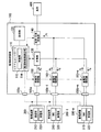
図1は、第1の実施形態の電源システム1の一例を示すブロック図である。電源システム1は、例えば、監視制御装置100と、複数の発電装置200−1、・・・200−k(kは1以上の任意の自然数)と、複数の蓄電装置300−1、・・・300−m(mは1以上の任意の自然数)と、負荷400とを含んでよいが、これに限定されない。電源システム1において、発電装置200−1、・・・200−kおよび蓄電装置300−1、・・・300−mは、電源システム1に対して互いに並列して接続されている。電源システム1は、蓄電装置300に蓄えられた電力と、発電装置200により発電された電力とを負荷400に供給可能なハイブリッド電源である。負荷400は、監視制御装置100から供給された電力を消費して動作する電気機器である。以下、発電装置を他の発電装置と区別しない場合には、「発電装置200」と記載し、蓄電装置を他の蓄電装置と区別しない場合には、「蓄電装置300」と記載する。
(First embodiment)
FIG. 1 is a block diagram illustrating an example of a power supply system 1 according to the first embodiment. The power supply system 1 includes, for example, a monitoring control device 100, a plurality of power generation devices 200-1,... Although 300-m (m is an arbitrary natural number of 1 or more) and the load 400 may be included, it is not limited to this. In the power supply system 1, the power generation devices 200-1 to 200 -k and the power storage devices 300-1 to 300 -m are connected to the power supply system 1 in parallel with each other. The power supply system 1 is a hybrid power supply that can supply the power stored in the power storage device 300 and the power generated by the power generation device 200 to the load 400. The load 400 is an electric device that operates by consuming electric power supplied from the monitoring control device 100. Hereinafter, when the power generation device is not distinguished from other power generation devices, it is described as “power generation device 200”, and when the power storage device is not distinguished from other power storage devices, it is described as “power storage device 300”.

図2は、第1の実施形態の電源システム1における監視制御装置100、発電装置200、および蓄電装置300の一例を示すブロック図である。なお、図2に示した電源システム1は、発電装置200が単一である一例を示している。   FIG. 2 is a block diagram illustrating an example of the monitoring control device 100, the power generation device 200, and the power storage device 300 in the power supply system 1 according to the first embodiment. In addition, the power supply system 1 shown in FIG. 2 shows an example in which the power generation device 200 is single.

監視制御装置100は、システムコントローラ110と、記憶部120と、充電器130と、直流−交流変換部140と、発電用開閉器150と、複数の蓄電用開閉器160−1、・・・160−mとを含んでよいが、これに限定されない。以下、蓄電用開閉器を他の蓄電用開閉器と区別しない場合には、「蓄電用開閉器160」と記載する。   The monitoring control device 100 includes a system controller 110, a storage unit 120, a charger 130, a DC-AC conversion unit 140, a power generation switch 150, and a plurality of power storage switches 160-1,. -M may be included, but is not limited thereto. Hereinafter, when the storage switch is not distinguished from other storage switches, it is referred to as “storage switch 160”.

システムコントローラ110は、制御部112と、監視制御側通信部114とを含んでよいが、これに限定されない。制御部112は、例えばCPU(Central Processing Unit)等のプロセッサがプログラムメモリに格納されたプログラムを実行することにより実現される。また、制御部112のうち一部または全部は、LSI(Large Scale Integration)、ASIC(Application Specific Integrated Circuit)、またはFPGA(Field-Programmable Gate Array)等のハードウェアにより実現されてもよい。制御部112は、監視制御側通信部114を用いて、発電装置200および蓄電装置300と通信を行い、発電装置200および蓄電装置300を監視する。   The system controller 110 may include a control unit 112 and a monitoring control side communication unit 114, but is not limited thereto. The control unit 112 is realized by, for example, a processor such as a CPU (Central Processing Unit) executing a program stored in a program memory. Also, part or all of the control unit 112 may be realized by hardware such as LSI (Large Scale Integration), ASIC (Application Specific Integrated Circuit), or FPGA (Field-Programmable Gate Array). The control unit 112 communicates with the power generation device 200 and the power storage device 300 using the monitoring control side communication unit 114 to monitor the power generation device 200 and the power storage device 300.

監視制御側通信部114は、CAN(Controller Area Network)等の通信インターフェース回路である。監視制御側通信部114は、通信コネクタ100cを介して発電装置200および蓄電装置300と接続されている。監視制御側通信部114は、制御部112の制御に従って、発電装置200および蓄電装置300との間で通信信号を送受信する。また、監視制御側通信部114は、充電器130、直流−交流変換部140、発電用開閉器150、および蓄電用開閉器160との間で制御信号を送受信する。   The monitoring control side communication unit 114 is a communication interface circuit such as a CAN (Controller Area Network). The monitoring control side communication unit 114 is connected to the power generation device 200 and the power storage device 300 via the communication connector 100c. The monitoring control side communication unit 114 transmits and receives communication signals between the power generation device 200 and the power storage device 300 according to the control of the control unit 112. The monitoring control side communication unit 114 transmits and receives control signals to and from the charger 130, the DC-AC conversion unit 140, the power generation switch 150, and the storage switch 160.

記憶部120は、HDD(Hard Disc Drive)、フラッシュメモリ、EEPROM(Electrically Erasable Programmable Read Only Memory)、ROM(Read Only Memory)、またはRAM(Random Access Memory)等により実現される。また、記憶部120には、システムコントローラ110を実現するためのファームウェアやアプリケーションプログラム等の各種プログラム、各種プログラムを実行するためのパラメータ、各種プログラムの処理結果などが記憶される。   The storage unit 120 is realized by an HDD (Hard Disc Drive), a flash memory, an EEPROM (Electrically Erasable Programmable Read Only Memory), a ROM (Read Only Memory), a RAM (Random Access Memory), or the like. The storage unit 120 also stores various programs such as firmware and application programs for realizing the system controller 110, parameters for executing the various programs, processing results of the various programs, and the like.

充電器130は、発電用開閉器150から供給された電力(発電電力Pg)の電圧を変換する電圧変換回路を含む。充電器130は、変換した電力を、蓄電装置300または直流−交流変換部140に供給する。   The charger 130 includes a voltage conversion circuit that converts the voltage of power (generated power Pg) supplied from the power generation switch 150. The charger 130 supplies the converted power to the power storage device 300 or the DC-AC converter 140.

直流−交流変換部140は、供給された直流電力を交流電力に変換する電力変換回路を含む。直流−交流変換部140は、充電器130および蓄電装置300から直流電力が供給される。直流−交流変換部140は、変換した交流電力を負荷400に供給する。   The DC-AC converter 140 includes a power conversion circuit that converts supplied DC power into AC power. The DC-AC converter 140 is supplied with DC power from the charger 130 and the power storage device 300. The DC-AC converter 140 supplies the converted AC power to the load 400.

充電器130は、発電装置200ごとに、複数設けられてもよい。また、直流−交流変換部140は、充電器130を介して供給された発電電力Pgを変換する直流−交流変換部と、発蓄電用開閉器160を介して供給されたバッテリ電力Pbを変換する直流−交流変換部との2台であってもよい。   A plurality of chargers 130 may be provided for each power generation device 200. Further, the DC-AC converter 140 converts the DC-AC converter that converts the generated power Pg supplied via the charger 130 and the battery power Pb supplied via the power generation switch 160. Two units with a DC-AC converter may be used.

発電用開閉器150は、例えば、FET(Field Effect Transistor)スイッチである。発電用開閉器150は、機械的に動作する電力用のリレー回路であってもよい。発電用開閉器150は、監視制御装置100の発電用コネクタ100aと、充電器130との間に設けられている。発電用開閉器150には、発電用コネクタ100aを介して、発電電力Pgが供給される。発電用開閉器150は、制御部112の制御に従って、導通状態と遮断状態との間で状態が切り替えられる。発電用開閉器150は、導通状態において発電電力Pgを充電器130に供給可能である。発電用開閉器150は、遮断状態において発電装置200と充電器130との間を絶縁する。   The power generation switch 150 is, for example, an FET (Field Effect Transistor) switch. The power generation switch 150 may be a mechanically operating power relay circuit. The power generation switch 150 is provided between the power generation connector 100 a of the monitoring control device 100 and the charger 130. The power generation switch 150 is supplied with generated power Pg via the power generation connector 100a. The state of the power generation switch 150 is switched between a conduction state and a cutoff state under the control of the control unit 112. The power generation switch 150 can supply the generated power Pg to the charger 130 in the conductive state. The power generation switch 150 insulates the power generation device 200 from the charger 130 in the cut-off state.

蓄電用開閉器160は、例えば、FETスイッチである。蓄電用開閉器160は、機械的に動作する電力用のリレー回路であってもよい。蓄電用開閉器160は、監視制御装置100の蓄電用コネクタ100b−1、・・・100b−mと、充電器130および直流−交流変換部140との間に設けられている。以下、蓄電用コネクタを他の蓄電用コネクタと区別しない場合には「蓄電用コネクタ100b」と記載する。蓄電用開閉器160には、蓄電用コネクタ100bを介してバッテリ電力Pbが供給される。また、蓄電用開閉器160には、充電器130を介して発電電力Pgが供給される。蓄電用開閉器160は、制御部112の制御に従って、導通状態と遮断状態との間で状態が切り替えられる。蓄電用開閉器160は、導通状態において発電電力Pgを充電器130に供給可能である。また、蓄電用開閉器160は、導通状態においてバッテリ電力Pbを直流−交流変換部140に供給可能である。蓄電用開閉器160は、遮断状態において蓄電用コネクタ100bと充電器130および直流−交流変換部140との間を絶縁する。   The storage switch 160 is, for example, an FET switch. The power storage switch 160 may be a mechanically operated power relay circuit. The storage switch 160 is provided between the storage connectors 100b-1,... 100b-m of the monitoring control device 100, and the charger 130 and the DC-AC converter 140. Hereinafter, the power storage connector is referred to as “power storage connector 100b” when it is not distinguished from other power storage connectors. Battery power Pb is supplied to the storage switch 160 via the storage connector 100b. The power storage switch 160 is supplied with the generated power Pg via the charger 130. The state of the storage switch 160 is switched between a conduction state and a cutoff state according to the control of the control unit 112. The storage switch 160 can supply the generated power Pg to the charger 130 in the conductive state. In addition, the storage switch 160 can supply the battery power Pb to the DC-AC converter 140 in the conductive state. The storage switch 160 insulates between the storage connector 100b, the charger 130, and the DC-AC converter 140 in the cut-off state.

発電装置200は、発電側通信部210と、発電部220とを含んでよいが、これに限定されない。発電側通信部210は、CAN等の通信インターフェース回路である。発電側通信部210は、通信コネクタ100cを介して、システムコントローラ110との間で通信信号を送受信する。発電部220は、太陽電池パネル、燃料電池システム、ディーゼル型発電機などの発電装置を含む。発電部220は、発電電力Pgを、監視制御装置100を介して蓄電装置300または負荷400に供給する。   The power generation apparatus 200 may include the power generation side communication unit 210 and the power generation unit 220, but is not limited thereto. The power generation side communication unit 210 is a communication interface circuit such as CAN. The power generation side communication unit 210 transmits and receives communication signals to and from the system controller 110 via the communication connector 100c. The power generation unit 220 includes a power generation device such as a solar cell panel, a fuel cell system, or a diesel generator. The power generation unit 220 supplies the generated power Pg to the power storage device 300 or the load 400 via the monitoring control device 100.

発電装置200は、発電装置200の状態を要求するコマンドを、システムコントローラ110から受信する。発電装置200は、コマンドを受信したことに応じて、発電装置200の状態を含むレスポンスをシステムコントローラ110に送信する。このとき、発電装置200は、発電装置200の状態として、発電装置200の動作または非動作、発電部220の現在の発電電力値などを送信する。   The power generation device 200 receives a command requesting the state of the power generation device 200 from the system controller 110. The power generation device 200 transmits a response including the state of the power generation device 200 to the system controller 110 in response to receiving the command. At this time, the power generation apparatus 200 transmits, as the state of the power generation apparatus 200, the operation or non-operation of the power generation apparatus 200, the current generated power value of the power generation unit 220, and the like.

蓄電装置300は、BMU(Battery Management Unit)310と、蓄電部320とを含んでよいが、これに限定されない。BMU310は、例えば、CAN等の通信インターフェース回路、およびCPUなどの制御回路を含む。BMU310は、蓄電部320のSOC(State of Charge)などの状態情報を取得する。BMU310は、システムコントローラ110との間で通信信号を送受信することで、状態情報などの情報を送受信する。蓄電部320は、リチウムイオン電池、鉛蓄電池、ニッケル水素電池などであってもよいが、これに限定されない。蓄電部320には、監視制御装置100を介して、発電装置200から発電電力Pgが供給される。蓄電部320は、放電したバッテリ電力Pbを、監視制御装置100を介して負荷400に供給する。   The power storage device 300 may include a BMU (Battery Management Unit) 310 and a power storage unit 320, but is not limited thereto. The BMU 310 includes, for example, a communication interface circuit such as CAN and a control circuit such as a CPU. The BMU 310 acquires state information such as SOC (State of Charge) of the power storage unit 320. The BMU 310 transmits and receives information such as state information by transmitting and receiving communication signals to and from the system controller 110. The power storage unit 320 may be a lithium ion battery, a lead storage battery, a nickel metal hydride battery, or the like, but is not limited thereto. The power storage unit 320 is supplied with the generated power Pg from the power generation device 200 via the monitoring control device 100. The power storage unit 320 supplies the discharged battery power Pb to the load 400 via the monitoring control device 100.

蓄電装置300は、蓄電装置300の状態を要求するコマンドを、システムコントローラ110から受信する。蓄電装置300は、コマンドを受信したことに応じて、蓄電装置300の状態を含むレスポンスをシステムコントローラ110に送信する。このとき、BMU310は、蓄電装置300の状態として、蓄電装置300の動作または非動作、蓄電部320の現在の蓄電量などを送信する。   The power storage device 300 receives a command for requesting the state of the power storage device 300 from the system controller 110. In response to receiving the command, power storage device 300 transmits a response including the state of power storage device 300 to system controller 110. At this time, the BMU 310 transmits, as the state of the power storage device 300, the operation or non-operation of the power storage device 300, the current power storage amount of the power storage unit 320, and the like.

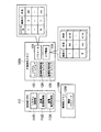
以下、第1の実施形態のシステムコントローラ110について説明する。図3は、第1の実施形態のシステムコントローラ110の制御部112および記憶部120の一例を示す図である。記憶部120は、例えば、不揮発性メモリ120Aと、揮発性メモリ120Bとを含むが、これに限定されない。   Hereinafter, the system controller 110 of the first embodiment will be described. FIG. 3 is a diagram illustrating an example of the control unit 112 and the storage unit 120 of the system controller 110 according to the first embodiment. The storage unit 120 includes, for example, a nonvolatile memory 120A and a volatile memory 120B, but is not limited thereto.

制御部112は、システム制御部1120と、発電監視制御部1122と、蓄電監視制御部1124とを含んでよいが、これに限定されない。システム制御部1120は、システムコントローラ110のCPUが不揮発性メモリ120Aに記憶されたシステムファームウェア122を実行することにより実現される機能部である。発電監視制御部1122は、システムコントローラ110のCPUが不揮発性メモリ120Aに記憶された発電監視制御ファームウェア124を実行することにより実現される機能部である。蓄電監視制御部1124は、システムコントローラ110のCPUが不揮発性メモリ120Aに記憶された蓄電監視制御ファームウェア126を実行することにより実現される機能部である。   The control unit 112 may include a system control unit 1120, a power generation monitoring control unit 1122, and a power storage monitoring control unit 1124, but is not limited thereto. The system control unit 1120 is a functional unit realized by the CPU of the system controller 110 executing the system firmware 122 stored in the nonvolatile memory 120A. The power generation monitoring control unit 1122 is a functional unit realized by the CPU of the system controller 110 executing the power generation monitoring control firmware 124 stored in the nonvolatile memory 120A. The power storage monitoring control unit 1124 is a functional unit realized by the CPU of the system controller 110 executing the power storage monitoring control firmware 126 stored in the nonvolatile memory 120A.

システム制御部1120は、監視制御側通信部114を用いて、発電側通信部210およびBMU310と通信を行う。システム制御部1120は、発電装置200および蓄電装置300を識別する機器ID(identification)を、発電装置200および蓄電装置300に付与する。システム制御部1120は、連続する識別番号を、機器IDとして発電装置200および蓄電装置300に付与するが、これに限定されない。システム制御部1120は、発電装置200または蓄電装置300の製造番号などの発電装置200および蓄電装置300を属性に基づく符号列を生成して、発電装置200および蓄電装置300に付与してもよい。   The system control unit 1120 communicates with the power generation side communication unit 210 and the BMU 310 using the monitoring control side communication unit 114. The system control unit 1120 gives a device ID (identification) for identifying the power generation device 200 and the power storage device 300 to the power generation device 200 and the power storage device 300. The system control unit 1120 assigns consecutive identification numbers to the power generation device 200 and the power storage device 300 as device IDs, but is not limited thereto. The system control unit 1120 may generate a code string based on the attribute of the power generation device 200 and the power storage device 300 such as the serial number of the power generation device 200 or the power storage device 300 and assign the code string to the power generation device 200 and the power storage device 300.

システム制御部1120は、発電装置200および蓄電装置300に付与した機器IDを、パラメータ128として不揮発性メモリ120Aに書き込む。また、システム制御部1120は、機器IDに対応して、発電用コネクタ100aを識別するコネクタIDと、発電装置200または蓄電装置300の状態とをパラメータ128として不揮発性メモリ120Aに書き込む。パラメータ128は、システムコントローラ110が起動した場合に、制御部112により不揮発性メモリ120Aから読み出され、最新のパラメータ128#として揮発性メモリ120Bに書き込まれる。最新パラメータ128#は、例えば電源システム1の構成が変更した場合に、システム制御部1120により更新される。   The system control unit 1120 writes the device ID assigned to the power generation device 200 and the power storage device 300 as the parameter 128 in the nonvolatile memory 120A. Further, the system control unit 1120 writes the connector ID for identifying the power generation connector 100a and the state of the power generation device 200 or the power storage device 300 as parameters 128 in the nonvolatile memory 120A corresponding to the device ID. When the system controller 110 is activated, the parameter 128 is read from the non-volatile memory 120A by the control unit 112 and written to the volatile memory 120B as the latest parameter 128 #. The latest parameter 128 # is updated by the system control unit 1120, for example, when the configuration of the power supply system 1 is changed.

また、システム制御部1120は、パラメータ128のログ情報129を不揮発性メモリ120Aに書き込む。ログ情報129は、過去に監視制御装置100に接続された発電装置200または蓄電装置300の機器ID、発電装置200または蓄電装置300の状態、および時刻情報を対応づけた情報である。ログ情報129は、パラメータ128が変更される度に、変更する前のパラメータ128として不揮発性メモリ120Aに書き込まれてよいが、これに限定されない。   Further, the system control unit 1120 writes the log information 129 of the parameter 128 in the nonvolatile memory 120A. The log information 129 is information in which the device ID of the power generation device 200 or the power storage device 300 connected to the monitoring control device 100 in the past, the state of the power generation device 200 or the power storage device 300, and time information are associated with each other. Each time the parameter 128 is changed, the log information 129 may be written in the nonvolatile memory 120A as the parameter 128 before being changed, but is not limited thereto.

時刻情報は、発電装置200または蓄電装置300の接続を検出した時刻またはシステム制御部1120により機器IDを付与した時刻であってもよいが、これに限定されない。時刻情報には、発電装置200または蓄電装置300の接続を検出した時刻またはシステム制御部1120により機器IDを付与した時刻に加え、監視制御装置100から取りはずされた時刻を含んでいてもよい。システムコントローラ110は、時刻情報を生成するための内部クロック(不図示)を含んでよいが、これに限定されず、外部装置から時刻情報を取得してもよい。   The time information may be the time when connection of the power generation device 200 or the power storage device 300 is detected or the time when the device ID is given by the system control unit 1120, but is not limited thereto. The time information may include the time removed from the monitoring control device 100 in addition to the time when the connection of the power generation device 200 or the power storage device 300 is detected or the time when the system control unit 1120 assigns the device ID. The system controller 110 may include an internal clock (not shown) for generating time information, but is not limited thereto, and may acquire time information from an external device.

発電監視制御部1122は、発電装置200に付与された機器IDを用いて、発電側通信部210と通信を行う。発電監視制御部1122は、発電装置200の状態を要求するコマンドを送信し、発電側通信部210からコマンドに応答するレスポンスを受信する。これにより、発電監視制御部1122は、発電装置200の動作または非動作、発電装置200の現在の発電電力値などの状態を認識する。発電監視制御部1122は、認識した発電装置200の状態を、最新パラメータ128#における状態として揮発性メモリ120Bに書き込む。また、発電監視制御部1122は、外部装置から受信した要求に基づいて、発電用開閉器150の開閉を制御する。   The power generation monitoring control unit 1122 communicates with the power generation side communication unit 210 using the device ID assigned to the power generation device 200. The power generation monitoring control unit 1122 transmits a command requesting the state of the power generation device 200 and receives a response responding to the command from the power generation side communication unit 210. Thereby, the power generation monitoring control unit 1122 recognizes the state of the power generation device 200 such as the operation or non-operation and the current power generation value of the power generation device 200. The power generation monitoring control unit 1122 writes the recognized state of the power generation device 200 in the volatile memory 120B as the state in the latest parameter 128 #. The power generation monitoring control unit 1122 controls the opening / closing of the power generation switch 150 based on a request received from an external device.

蓄電監視制御部1124は、蓄電装置300に付与された機器IDを用いて、BMU310と通信を行う。蓄電監視制御部1124は、蓄電装置300の状態を要求するコマンドを送信し、BMU310からコマンドに応答するレスポンスを受信する。これにより、蓄電監視制御部1124は、蓄電装置300の動作または非動作、蓄電装置300の現在のSOCなどを認識する。蓄電監視制御部1124は、認識した蓄電装置300の状態を、最新パラメータ128#における状態として揮発性メモリ120Bに書き込む。また、蓄電監視制御部1124は、蓄電装置300に充放電をさせる場合に、充電器130および蓄電用開閉器160を制御する。さらに、蓄電監視制御部1124は、直流−交流変換部140を制御して、負荷400にバッテリ電力Pbを供給する。   The power storage monitoring control unit 1124 communicates with the BMU 310 using the device ID assigned to the power storage device 300. The power storage monitoring control unit 1124 transmits a command requesting the state of the power storage device 300 and receives a response responding to the command from the BMU 310. Thereby, the power storage monitoring control unit 1124 recognizes the operation or non-operation of the power storage device 300, the current SOC of the power storage device 300, and the like. The power storage monitoring control unit 1124 writes the recognized state of the power storage device 300 in the volatile memory 120B as the state in the latest parameter 128 #. The power storage monitoring control unit 1124 controls the charger 130 and the power storage switch 160 when the power storage device 300 is charged and discharged. Furthermore, the power storage monitoring control unit 1124 controls the DC / AC conversion unit 140 to supply the battery power Pb to the load 400.

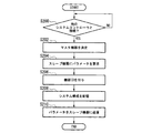
以下、監視制御装置100に接続された発電装置200および蓄電装置300に機器IDを付与することについて説明する。図4は、第1の実施形態のシステムコントローラ110における処理の流れの一例を示すフローチャートである。   Hereinafter, giving device IDs to the power generation device 200 and the power storage device 300 connected to the monitoring control device 100 will be described. FIG. 4 is a flowchart illustrating an example of a processing flow in the system controller 110 according to the first embodiment.

システム制御部1120は、まず、電源システム1が起動したか否かを判定する(ステップS100)。システム制御部1120は、少なくとも監視制御装置100が起動した場合、電源システム1が起動したと判定する。また、システム制御部1120は、監視制御装置100に加え、監視制御装置100に接続された発電装置200および蓄電装置300のうち一部が起動した場合に、電源システム1が起動したと判定してもよい。   First, the system control unit 1120 determines whether or not the power supply system 1 is activated (step S100). The system control unit 1120 determines that the power supply system 1 is activated at least when the monitoring control device 100 is activated. In addition to the monitoring control device 100, the system control unit 1120 determines that the power supply system 1 has started when a part of the power generation device 200 and the power storage device 300 connected to the monitoring control device 100 is started. Also good.

システム制御部1120は、コネクタIDの「1」を指定する(ステップS102)。次に、システム制御部1120は、コネクタIDの「1」に対応する発電用コネクタ100aまたは蓄電用コネクタ100bに接続された発電装置200または蓄電装置300が動作中であるか否かを判定する(ステップS104)。このとき、システム制御部1120は、監視制御側通信部114を用いて、コネクタIDの「1」に対応する発電用コネクタ100aまたは蓄電用コネクタ100bに接続された発電装置200または蓄電装置300の発電側通信部210またはBMU310と通信を行う。システム制御部1120は、通信の結果、状態が「動作中」である場合に、発電装置200または蓄電装置300が動作中であると判定する。   The system control unit 1120 designates “1” as the connector ID (step S102). Next, the system control unit 1120 determines whether or not the power generation device 200 or the power storage device 300 connected to the power generation connector 100a or the power storage connector 100b corresponding to the connector ID “1” is operating ( Step S104). At this time, the system control unit 1120 uses the monitoring control side communication unit 114 to generate power of the power generation device 200 or the power storage device 300 connected to the power generation connector 100a or the power storage connector 100b corresponding to the connector ID “1”. Communicates with the side communication unit 210 or the BMU 310. The system control unit 1120 determines that the power generation device 200 or the power storage device 300 is operating when the state is “operating” as a result of communication.

システム制御部1120は、発電装置200または蓄電装置300が動作中である場合、動作中である発電装置200または蓄電装置300をID付与対象装置として設定する(ステップS106)。システム制御部1120は、発電装置200または蓄電装置300が動作中ではない場合、機器IDを付与しないことを認識する(ステップS108)。   When the power generation device 200 or the power storage device 300 is operating, the system control unit 1120 sets the power generation device 200 or the power storage device 300 that is operating as an ID assignment target device (step S106). When the power generation device 200 or the power storage device 300 is not in operation, the system control unit 1120 recognizes that no device ID is given (step S108).

次にシステム制御部1120は、未判定の発電用コネクタ100aおよび蓄電用コネクタ100bがあるか否かを判定する(ステップS110)。システム制御部1120は、未判定の発電用コネクタ100aおよび蓄電用コネクタ100bがある場合、コネクタIDをインクリメントして(ステップS112)、ステップS104からステップS110の処理を繰り返す。   Next, the system control unit 1120 determines whether or not there is an undetermined power generation connector 100a and a power storage connector 100b (step S110). When there is an undetermined power generation connector 100a and power storage connector 100b, the system control unit 1120 increments the connector ID (step S112), and repeats the processing from step S104 to step S110.

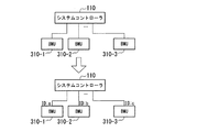
システム制御部1120は、未判定の発電用コネクタ100aおよび蓄電用コネクタ100bがない場合、ID付与対象装置に機器IDを付与する(ステップS114)。図5は、第1の実施形態のシステム構成の一例を示す図である。システム制御部1120は、監視制御装置100に3台の蓄電装置300が接続されている場合に、3台のBMU310−1、310−2、および310−3のそれぞれに、機器ID:a、機器ID:b、および機器ID:cを付与する。   When there is no undetermined power generation connector 100a and power storage connector 100b, the system control unit 1120 assigns a device ID to the ID assignment target device (step S114). FIG. 5 is a diagram illustrating an example of a system configuration according to the first embodiment. When three power storage devices 300 are connected to the monitoring control device 100, the system control unit 1120 includes a device ID: a and a device for each of the three BMUs 310-1, 310-2, and 310-3. ID: b and device ID: c are assigned.

次に、システム制御部1120は、システム構成を記憶する(ステップS116)。このとき、システム制御部1120は、コネクタID、付与した機器ID、および発電装置200または蓄電装置300の状態を最新パラメータ128#として揮発性メモリ120Bに書き込む。また、システム制御部1120は、システム構成をパラメータ128として不揮発性メモリ120Aに書き込んでもよい。   Next, the system control unit 1120 stores the system configuration (step S116). At this time, the system control unit 1120 writes the connector ID, the assigned device ID, and the state of the power generation device 200 or the power storage device 300 in the volatile memory 120B as the latest parameter 128 #. In addition, the system control unit 1120 may write the system configuration as the parameter 128 in the nonvolatile memory 120A.

次にシステム制御部1120は、システム変更を検出したか否かを判定する(ステップS118)。システム制御部1120は、監視制御装置100に接続されている発電装置200または蓄電装置300の数が変更した場合に、システム変更を検出したと判定するが、これに限定されない。システム制御部1120は、システム変更を検出していない場合には待機する。   Next, the system control unit 1120 determines whether a system change has been detected (step S118). The system control unit 1120 determines that a system change has been detected when the number of power generation devices 200 or power storage devices 300 connected to the monitoring control device 100 is changed, but is not limited thereto. The system control unit 1120 waits if no system change is detected.

システム制御部1120は、システム変更を検出した場合、システム構成をクリアする(ステップS120)。このとき、システム制御部1120は、最新パラメータ128#を消去する。なお、システム制御部1120は、最新パラメータ128#として不揮発性メモリ120Aに記憶したパラメータ128を、ログ情報129に書き換える。   When detecting a system change, the system control unit 1120 clears the system configuration (step S120). At this time, the system control unit 1120 deletes the latest parameter 128 #. The system control unit 1120 rewrites the parameter 128 stored in the nonvolatile memory 120A as the latest parameter 128 # into the log information 129.

システム制御部1120は、システム変更後のID付与対象装置に機器IDを付与する(ステップS122)。このとき、システム制御部1120は、ステップS102〜S114の処理を行う。システム制御部1120は、システム変更後のID付与対象装置に対する機器IDの付与が完了した場合、ステップS116においてシステム変更後のシステム構成を記憶する(ステップS116)。このとき、システム制御部1120は、システム変更後のパラメータ128#を揮発性メモリ120Bに書き込むと共に、システム変更後のパラメータ128を不揮発性メモリ120Aに書き込む。   The system control unit 1120 assigns a device ID to the ID assignment target device after the system change (step S122). At this time, the system control unit 1120 performs steps S102 to S114. When the device ID assignment to the ID assignment target device after the system change is completed, the system control unit 1120 stores the system configuration after the system change in step S116 (step S116). At this time, the system control unit 1120 writes the parameter 128 # after the system change to the volatile memory 120B, and also writes the parameter 128 after the system change to the nonvolatile memory 120A.

図6は、第1の実施形態のシステム構成の他の一例を示す図である。システム制御部1120は、監視制御装置100に3台の蓄電装置300が接続されている状態で、1台の蓄電装置300が追加して接続された場合に、システム変更を検出する。システム制御部1120は、BMU310310−1〜310−3に既に付与された機器ID(a、b、およびc)をクリアし、4台のBMU310−1〜310−4のそれぞれに、新たな機器ID:d、機器ID:e、機器ID:f、および機器ID:gを付与する。   FIG. 6 is a diagram illustrating another example of the system configuration according to the first embodiment. The system control unit 1120 detects a system change when one power storage device 300 is additionally connected while the three power storage devices 300 are connected to the monitoring control device 100. The system control unit 1120 clears the device IDs (a, b, and c) already assigned to the BMUs 310310-1 to 310-3, and assigns a new device ID to each of the four BMUs 310-1 to 310-4. : D, device ID: e, device ID: f, and device ID: g are assigned.

システムコントローラ110は、新たな機器IDを用いて、4台のBMU310−1〜310−4のそれぞれと通信を行うことで、4台のBMU310を含む4台の蓄電装置300の蓄電容量を取得する。システムコントローラ110は、取得した4台分の蓄電容量を合計して、電源システム1の総蓄電容量としてユーザに提示する。なお、システムコントローラ110は、複数の発電装置200が接続されている場合、複数台分の発電容量を合計して、電源システム1の総発電容量としてユーザに提示する。   The system controller 110 acquires the storage capacities of the four power storage devices 300 including the four BMUs 310 by communicating with each of the four BMUs 310-1 to 310-4 using the new device ID. . The system controller 110 totals the acquired storage capacities of the four units and presents them to the user as the total storage capacity of the power supply system 1. When a plurality of power generation devices 200 are connected, the system controller 110 adds up the power generation capacities for a plurality of units and presents them to the user as the total power generation capacity of the power supply system 1.

図7は、第1の実施形態のシステム構成の他の一例を示す図である。システム制御部1120は、監視制御装置100に3台の蓄電装置300が接続されている状態で、1台のBMU310−3が監視制御装置100から取り外された場合に、システム変更を検出する。システム制御部1120は、既に付与された機器ID(a、b、およびc)のうち、取りはずされたBMU310−3に付与した機器ID「c」を、最新パラメータ128#およびパラメータ128から削除する。   FIG. 7 is a diagram illustrating another example of the system configuration according to the first embodiment. The system control unit 1120 detects a system change when one BMU 310-3 is removed from the monitoring control device 100 in a state where the three power storage devices 300 are connected to the monitoring control device 100. The system control unit 1120 deletes the device ID “c” assigned to the removed BMU 310-3 from the device IDs (a, b, and c) already assigned, from the latest parameter 128 # and the parameter 128. .

システムコントローラ110は、削除された機器IDを除く機器IDを用いて、2台のBMU310−1および310−2のそれぞれと通信を行うことで、2台のBMU310を含む2台の蓄電装置300の蓄電容量を取得し、電源システム1の総蓄電容量としてユーザに提示する。   The system controller 110 communicates with each of the two BMUs 310-1 and 310-2 using the device IDs other than the deleted device IDs, so that the two power storage devices 300 including the two BMUs 310 are connected. The storage capacity is acquired and presented to the user as the total storage capacity of the power supply system 1.

以上説明した第1の実施形態の電源システム1は、監視制御装置100が起動した場合に、監視制御側通信部114を用いて取得した発電装置200および蓄電装置300の状態に基づいて発電装置200および蓄電装置300が動作可能であるか否かをそれぞれ判定し、動作可能である発電装置200および蓄電装置300に機器IDを付与する。第1の実施形態の電源システム1によれば、予め設定された機器IDではなく、監視制御装置100により認識した発電装置200および蓄電装置300に機器IDに付与するので、監視制御装置100に発電装置200および蓄電装置300を接続する自由度を高くすることができ、システム変更に対する利便性を向上させることができる。   The power supply system 1 of the first embodiment described above is based on the state of the power generation device 200 and the power storage device 300 acquired using the monitoring control side communication unit 114 when the monitoring control device 100 is activated. In addition, it is determined whether or not the power storage device 300 is operable, and device IDs are assigned to the power generation device 200 and the power storage device 300 that are operable. According to the power supply system 1 of the first embodiment, since the device ID is assigned to the power generation device 200 and the power storage device 300 recognized by the monitoring control device 100 instead of the preset device ID, the monitoring control device 100 generates power. The degree of freedom for connecting the device 200 and the power storage device 300 can be increased, and convenience for system change can be improved.

また、第1の実施形態の電源システム1によれば、監視制御装置100に対する発電装置200および蓄電装置300の接続数が変更した場合、接続数が変更する前に付与していた機器IDに代えて、接続数が変更した後に監視制御装置100に接続されている発電装置200または蓄電装置300に、新たな機器IDを付与する。これにより、第1の実施形態の電源システム1によれば、発電装置200または蓄電装置300が動作している状態で、監視制御装置100に対する発電装置200または蓄電装置300の接続数が変更されても、新たな機器IDを用いて、発電装置200または蓄電装置300と通信を行うことができる。この結果、第1の実施形態の電源システム1によれば、発電装置200または蓄電装置300の動作中であっても動的にシステム変更をすることができ、更に利便性を向上させることができる。   Moreover, according to the power supply system 1 of 1st Embodiment, when the number of connection of the electric power generating apparatus 200 and the electrical storage apparatus 300 with respect to the monitoring control apparatus 100 changes, it replaces with apparatus ID provided before the number of connections changed. Thus, a new device ID is assigned to the power generation device 200 or the power storage device 300 connected to the monitoring control device 100 after the number of connections is changed. Thereby, according to the power supply system 1 of 1st Embodiment, the number of connection of the electric power generating apparatus 200 or the electrical storage apparatus 300 with respect to the monitoring control apparatus 100 is changed in the state which the electric power generating apparatus 200 or the electrical storage apparatus 300 is operating. In addition, communication with the power generation device 200 or the power storage device 300 can be performed using the new device ID. As a result, according to the power supply system 1 of the first embodiment, the system can be dynamically changed even during the operation of the power generation device 200 or the power storage device 300, and the convenience can be further improved. .

さらに、第1の実施形態の電源システム1によれば、発電装置200または蓄電装置300の属性情報に基づいて機器IDを生成するので、ログ情報129に含まれる機器IDを参照することにより、どのような機器が監視制御装置100に接続されていたかを解析することができる。この結果、第1の実施形態の電源システム1によれば、発電装置200または蓄電装置300の利用履歴の解析、電源システム1の故障原因の解析、またはメンテナンスに対する利便性を向上させることができる。また、第1の実施形態の電源システム1によれば、ログ情報129をトレーサビリティ管理に利用させることができる。   Furthermore, according to the power supply system 1 of 1st Embodiment, since apparatus ID is produced | generated based on the attribute information of the electric power generating apparatus 200 or the electrical storage apparatus 300, by referring to apparatus ID contained in the log information 129, which It is possible to analyze whether such a device is connected to the monitoring control apparatus 100. As a result, according to the power supply system 1 of the first embodiment, it is possible to improve the usage history analysis of the power generation apparatus 200 or the power storage apparatus 300, the cause of failure of the power supply system 1, or the convenience for maintenance. Further, according to the power supply system 1 of the first embodiment, the log information 129 can be used for traceability management.

さらに、第1の実施形態の電源システム1によれば、発電装置200または蓄電装置300に付与する機器IDに時刻情報を付加した情報を、ログ情報129として不揮発性メモリ120Aに書き込むので、より正確な電源システム1の利用履歴を利用者などに提示することができ、更に利便性を向上させることができる。   Furthermore, according to the power supply system 1 of the first embodiment, the information in which the time information is added to the device ID assigned to the power generation device 200 or the power storage device 300 is written in the nonvolatile memory 120A as the log information 129. The usage history of the power supply system 1 can be presented to the user and the convenience can be further improved.

(第2の実施形態)
以下、第2の実施形態の電源システム1Aについて説明する。第2の実施形態の電源システム1Aは、複数の監視制御装置100のシステムコントローラ110同士を接続し、何れか一つのシステムコントローラ110により複数の監視制御装置100に接続された発電装置200および蓄電装置300に機器IDを付与する点で、第1の実施形態の電源システム1とは異なる。以下、第1の実施形態の電源システム1と異なる点を中心にして説明する。
(Second Embodiment)
Hereinafter, the power supply system 1A of the second embodiment will be described. The power supply system 1A of the second embodiment connects the system controllers 110 of the plurality of monitoring control devices 100, and the power generation device 200 and the power storage device connected to the plurality of monitoring control devices 100 by any one system controller 110. It differs from the power supply system 1 of 1st Embodiment by the point which provides apparatus ID to 300. FIG. Hereinafter, a description will be given centering on differences from the power supply system 1 of the first embodiment.

図8は、第2の実施形態の電源システム1Aの一例を示す図である。電源システム1Aは、図8の上段に示すように、監視制御装置100Aに含まれるシステムコントローラ110Aに、複数の蓄電装置300Aに含まれるBMU310A−1、310A−2、および310A−3が接続されている。また、電源システム1Aは、監視制御装置100Bに含まれるシステムコントローラ110Bに、複数の蓄電装置300Bに含まれるBMU310B−1、310B−2、および310B−3が接続されている。なお、図8に示した電源システム1Aは、システムコントローラに複数の蓄電装置300が接続されているが、これに限定されない。システムコントローラには、発電装置200が接続されていてもよい。   FIG. 8 is a diagram illustrating an example of a power supply system 1A according to the second embodiment. In the power supply system 1A, as shown in the upper part of FIG. 8, BMUs 310A-1, 310A-2, and 310A-3 included in a plurality of power storage devices 300A are connected to a system controller 110A included in the monitoring control device 100A. Yes. In power supply system 1A, BMUs 310B-1, 310B-2, and 310B-3 included in a plurality of power storage devices 300B are connected to system controller 110B included in monitoring control device 100B. Note that the power supply system 1A illustrated in FIG. 8 has a plurality of power storage devices 300 connected to the system controller, but is not limited thereto. The power generator 200 may be connected to the system controller.

以下、図8の上段に示した電源システム1Aにおいて、システムコントローラ110Aと110Bとを接続した場合に、一つのシステムコントローラ110Aにより発電装置200および蓄電装置300を監視する処理について説明する。図9は、第2の実施形態におけるシステムコントローラ110Aの処理の流れの他の一例を示すフローチャートである。   Hereinafter, in the power supply system 1A shown in the upper part of FIG. 8, when the system controllers 110A and 110B are connected, a process of monitoring the power generation device 200 and the power storage device 300 by one system controller 110A will be described. FIG. 9 is a flowchart illustrating another example of the processing flow of the system controller 110A according to the second embodiment.

まず、システムコントローラ110Aは、他のシステムコントローラ110Bと接続されたか否かを判定する(ステップS200)。システムコントローラ110Aは、例えば、他の機器に状態を要求するコマンドを送信したことに対し、システムコントローラ110Bから応答を受信した場合に、他のシステムコントローラ110Bが接続されたことを認識する。システムコントローラ110Aは、他のシステムコントローラに接続されていない場合には待機する。   First, the system controller 110A determines whether or not it is connected to another system controller 110B (step S200). For example, when the system controller 110A receives a response from the system controller 110B in response to transmitting a command requesting a state to another device, the system controller 110A recognizes that the other system controller 110B is connected. The system controller 110A waits if it is not connected to another system controller.

システムコントローラ110Aは、システムコントローラ110Bが接続された場合、マスター機器を決定する(ステップS202)。システムコントローラ110Aおよびシステムコントローラ110Bは、所定の規則に基づいて、マスタースレーブ関係を確立する。電源システム1Aにおいて、図8の中段に示すように、システムコントローラ110Aがマスター機器であるものとし、システムコントローラ110Bがスレーブ機器であるものとする。   When the system controller 110B is connected, the system controller 110A determines a master device (step S202). The system controller 110A and the system controller 110B establish a master-slave relationship based on a predetermined rule. In the power supply system 1A, as shown in the middle part of FIG. 8, it is assumed that the system controller 110A is a master device and the system controller 110B is a slave device.

次に、システムコントローラ110Aは、スレーブ機器としてのシステムコントローラ110Bに、パラメータ128を要求するコマンドを送信する(ステップS204)。システムコントローラ110Bは、システムコントローラ110Aからパラメータ128を要求するコマンドを受信した場合、不揮発性メモリ120Aに記憶したパラメータ128または揮発性メモリ120Bに記憶した最新パラメータ128#を読み出して、システムコントローラ110Aに送信する。   Next, the system controller 110A transmits a command requesting the parameter 128 to the system controller 110B as a slave device (step S204). When the system controller 110B receives a command requesting the parameter 128 from the system controller 110A, the system controller 110B reads the parameter 128 stored in the nonvolatile memory 120A or the latest parameter 128 # stored in the volatile memory 120B and transmits the parameter 128 # to the system controller 110A. To do.

次に、システムコントローラ110Aは、システムコントローラ110Aに接続されている蓄電装置300およびシステムコントローラ110Bに接続されている蓄電装置300に機器IDを付与する(ステップS206)。システムコントローラ110Aは、例えば、自身に接続されている蓄電装置300に付与されている機器ID(a〜c)と、システムコントローラ110Bに接続されている蓄電装置300に付与されている機器ID(aおよびb)とを比較する。システムコントローラ110Aは、例えば、重複する機器ID(aおよびb)を、重複しない機器ID(dおよびe)に補正する。また、システムコントローラ110Aは、第1の実施形態と同様に、自身およびシステムコントローラ110Bに接続されている蓄電装置300に付与した機器IDをクリアし、新たな機器IDを生成してもよい。   Next, the system controller 110A gives a device ID to the power storage device 300 connected to the system controller 110A and the power storage device 300 connected to the system controller 110B (step S206). For example, the system controller 110A has a device ID (ac) assigned to the power storage device 300 connected to the system controller 110A and a device ID (a) assigned to the power storage device 300 connected to the system controller 110B. And b). For example, the system controller 110A corrects overlapping device IDs (a and b) to non-overlapping device IDs (d and e). Further, similarly to the first embodiment, the system controller 110A may clear the device ID assigned to the power storage device 300 connected to itself and the system controller 110B, and generate a new device ID.

次に、システムコントローラ110Aは、システム構成を記憶する(ステップS208)。このとき、システムコントローラ110Aは、自身のコネクタIDおよびシステムコントローラ110BのコネクタIDと、機器IDと、状態とを対応づけた最新パラメータ128#を生成し、揮発性メモリ120Bに書き込む。また、システムコントローラ110Aは、最新パラメータ128#と同じパラメータ128を不揮発性メモリ120Aに書き込む。   Next, the system controller 110A stores the system configuration (step S208). At this time, the system controller 110A generates the latest parameter 128 # in which its own connector ID, the connector ID of the system controller 110B, the device ID, and the state are associated with each other, and writes the latest parameter 128 # in the volatile memory 120B. Further, the system controller 110A writes the same parameter 128 as the latest parameter 128 # into the nonvolatile memory 120A.

次に、システムコントローラ110Aは、パラメータ128をスレーブ機器としてのシステムコントローラ110Bに送信する(ステップS210)。システムコントローラ110Bは、パラメータ128を受信した場合、パラメータ128を自身の不揮発性メモリ120Aに書き込む。   Next, the system controller 110A transmits the parameter 128 to the system controller 110B as a slave device (step S210). When the system controller 110B receives the parameter 128, the system controller 110B writes the parameter 128 into its own nonvolatile memory 120A.

システムコントローラ110Aは、新たな機器IDを用いて、5台のBMU310A−1〜310A−3、および310B−1および310B−2のそれぞれと通信を行うことで、5台のBMU310を含む5台の蓄電装置300の蓄電容量を取得する。システムコントローラ110Aは、取得した5台分の蓄電容量を合計して、電源システム1Aの総蓄電容量としてユーザに提示する。   The system controller 110A communicates with each of the five BMUs 310A-1 to 310A-3, and 310B-1 and 310B-2 using the new device ID, so that the five units including the five BMUs 310 are included. The storage capacity of the power storage device 300 is acquired. The system controller 110A totals the acquired storage capacities for the five units and presents them to the user as the total storage capacity of the power supply system 1A.

なお、システムコントローラ110Aは、図8の下段に示すように、システムコントローラ110Bに新たな蓄電装置300(BMU310B−3)が接続された場合、システム変更を検出する。この場合、システムコントローラ110Bは、自装置に蓄電装置300が接続されたことを検出し、検出結果をシステムコントローラ110Aに送信する。システムコントローラ110Aは、蓄電装置300(BMU310B−3)に機器IDを付与する。これにより、システムコントローラ110Aは、システムコントローラ110Bに新たに接続された蓄電装置300を含むシステム構成を記憶することができる。   As shown in the lower part of FIG. 8, system controller 110A detects a system change when a new power storage device 300 (BMU 310B-3) is connected to system controller 110B. In this case, system controller 110B detects that power storage device 300 is connected to its own device, and transmits the detection result to system controller 110A. System controller 110A assigns a device ID to power storage device 300 (BMU 310B-3). Thereby, the system controller 110A can store the system configuration including the power storage device 300 newly connected to the system controller 110B.

以上説明した第2の実施形態の電源システム1Aによれば、システムコントローラ110Aにシステムコントローラ110Bが接続された場合に、システムコントローラ110Aに接続されたBMU310、およびシステムコントローラ110Bに接続されたBMU310に新たに機器IDを付与するので、システムコントローラ110Aに接続されたBMU310およびシステムコントローラ110Bに接続されたBMU310を、マスター機器としてのシステムコントローラ110Aにより監視することができる。したがって、第2の実施形態の電源システム1Aによれば、複数の発電装置200および蓄電装置300をシステムコントローラ110Aにより集中監視することでき、電源システム1Aの最大接続数を増加させることができる。   According to the power supply system 1A of the second embodiment described above, when the system controller 110B is connected to the system controller 110A, the BMU 310 connected to the system controller 110A and the BMU 310 connected to the system controller 110B are newly added. Since the device ID is assigned to the BMU 310, the BMU 310 connected to the system controller 110A and the BMU 310 connected to the system controller 110B can be monitored by the system controller 110A as a master device. Therefore, according to the power supply system 1A of the second embodiment, a plurality of power generation devices 200 and power storage devices 300 can be centrally monitored by the system controller 110A, and the maximum number of connections of the power supply system 1A can be increased.

以上説明した少なくともひとつの実施形態によれば、発電装置200と蓄電装置300とのそれぞれに付与された機器IDを用いて発電装置200と蓄電装置300とのそれぞれと通信を行って情報を取得する監視制御側通信部114と、監視制御側通信部114が発電装置200と蓄電装置300とのそれぞれから取得した情報に基づいて、少なくとも充電器130および直流−交流変換部140を制御する制御部112と、を持ち、制御部112が、監視制御装置100が起動した場合に、監視制御側通信部114を用いて、接続されている発電装置200および蓄電装置300と通信を行って、通信結果に基づいて発電装置200および蓄電装置300が動作可能であるか否かを判定し、動作可能である発電装置200および蓄電装置300に機器IDを付与するので、監視制御装置100に対する発電装置200および蓄電装置300の接続数を変更した場合であっても、発電装置200および蓄電装置300にそれぞれ機器IDを付与して通信を行うことができ、システム変更に対する利便性を向上させることができる。   According to at least one embodiment described above, information is acquired by communicating with each of the power generation device 200 and the power storage device 300 using the device IDs assigned to the power generation device 200 and the power storage device 300, respectively. The monitoring control side communication unit 114 and the control unit 112 that controls at least the charger 130 and the DC-AC conversion unit 140 based on information acquired by the monitoring control side communication unit 114 from each of the power generation device 200 and the power storage device 300. When the monitoring control device 100 is activated, the control unit 112 communicates with the connected power generation device 200 and power storage device 300 using the monitoring control side communication unit 114, and displays the communication result. Based on whether or not power generation device 200 and power storage device 300 are operable, power generation device 200 and power storage device that are operable are determined. Since the device ID is assigned to 00, even if the number of connections of the power generation device 200 and the power storage device 300 to the monitoring control device 100 is changed, the device ID is assigned to the power generation device 200 and the power storage device 300 for communication. It is possible to improve the convenience for changing the system.

本発明のいくつかの実施形態を説明したが、これらの実施形態は、例として提示したものであり、発明の範囲を限定することは意図していない。これら実施形態は、その他の様々な形態で実施されることが可能であり、発明の要旨を逸脱しない範囲で、種々の省略、置き換え、変更を行うことができる。これら実施形態やその変形は、発明の範囲や要旨に含まれると同様に、特許請求の範囲に記載された発明とその均等の範囲に含まれるものである。   Although several embodiments of the present invention have been described, these embodiments are presented by way of example and are not intended to limit the scope of the invention. These embodiments can be implemented in various other forms, and various omissions, replacements, and changes can be made without departing from the spirit of the invention. These embodiments and their modifications are included in the scope and gist of the invention, and are also included in the invention described in the claims and the equivalents thereof.

1、1A…電源システム、100、100A、100B…監視制御装置、110、110A、110B…システムコントローラ、112…制御部、114…監視制御側通信部、120…記憶部、120A…不揮発性メモリ、120B…揮発性メモリ、122…システムファームウェア、124…発電監視制御ファームウェア、126…蓄電監視制御ファームウェア、128#…最新パラメータ、128…パラメータ、129…ログ情報、130…充電器、140…直流−交流変換部、150…発電用開閉器、160…蓄電用開閉器、200…発電装置、210…発電側通信部、220…発電部、300…蓄電装置、310…BMU、320…蓄電部、1120…システム制御部、1122…発電監視制御部、1124…蓄電監視制御部 DESCRIPTION OF SYMBOLS 1, 1A ... Power supply system, 100, 100A, 100B ... Monitoring control apparatus, 110, 110A, 110B ... System controller, 112 ... Control part, 114 ... Monitoring control side communication part, 120 ... Memory | storage part, 120A ... Non-volatile memory, 120B ... Volatile memory, 122 ... System firmware, 124 ... Power generation monitoring control firmware, 126 ... Power storage monitoring control firmware, 128 # ... Latest parameters, 128 ... Parameters, 129 ... Log information, 130 ... Charger, 140 ... DC-AC Conversion unit, 150 ... Power generation switch, 160 ... Power storage switch, 200 ... Power generation device, 210 ... Power generation side communication unit, 220 ... Power generation unit, 300 ... Power storage device, 310 ... BMU, 320 ... Power storage unit, 1120 ... System control unit, 1122 ... Power generation monitoring control unit, 1124 ... Power storage monitoring control unit

Claims (7)

通信機能を有する発電装置と、通信機能を有する1以上の蓄電装置とが接続可能な制御装置であって、
前記発電装置から供給された電力を用いて前記蓄電装置を充電する充電部と、
前記蓄電装置から供給された電力を変換する電力変換部と、
前記発電装置と前記蓄電装置とのそれぞれに付与された識別情報を用いて前記発電装置と前記蓄電装置とのそれぞれと通信を行って情報を取得する通信部と、
前記通信部が前記発電装置と前記蓄電装置とのそれぞれから取得した情報に基づいて、少なくとも前記充電部および前記電力変換部を制御する制御部と、を有し、
前記制御部は、自装置が起動した場合に、前記通信部を用いて、接続されている前記発電装置および前記蓄電装置と通信を行って、通信結果に基づいて前記発電装置および前記蓄電装置が動作可能であるか否かを判定し、動作可能である前記発電装置および前記蓄電装置に前記識別情報を付与する、
制御装置。
A control device capable of connecting a power generation device having a communication function and one or more power storage devices having a communication function,
A charging unit that charges the power storage device using electric power supplied from the power generation device;
A power converter that converts the power supplied from the power storage device;
A communication unit that acquires information by communicating with each of the power generation device and the power storage device using identification information given to each of the power generation device and the power storage device;
A control unit that controls at least the charging unit and the power conversion unit based on information acquired from each of the power generation device and the power storage device by the communication unit;
The control unit communicates with the connected power generation device and the power storage device using the communication unit when the own device is activated, and the power generation device and the power storage device are based on a communication result. It is determined whether or not it is operable, and the identification information is given to the power generation device and the power storage device that are operable.
Control device.
前記制御部は、前記発電装置および前記蓄電装置の接続数が変更した場合に、前記接続数が変更する前に付与していた識別情報に代えて、前記接続数が変更した場合に接続されている前記発電装置および前記蓄電装置に、新たな前記識別情報を付与する、
請求項1に記載の制御装置。
The control unit is connected when the number of connections is changed instead of the identification information given before the number of connections is changed when the number of connections of the power generation device and the power storage device is changed. Giving the identification information to the power generation device and the power storage device.
The control device according to claim 1.
前記制御部は、前記発電装置および前記蓄電装置のそれぞれの属性に基づいて前記識別情報を生成し、生成した前記識別情報を、前記属性に対応する前記発電装置および前記蓄電装置のそれぞれに付与する、
請求項1または2に記載の制御装置。
The control unit generates the identification information based on respective attributes of the power generation device and the power storage device, and assigns the generated identification information to each of the power generation device and the power storage device corresponding to the attribute. ,
The control device according to claim 1 or 2.
記憶部を備え、
前記制御部は、前記発電装置および前記蓄電装置に付与する前記識別情報に時刻情報を付加したログ情報を生成し、生成した前記ログ情報を前記記憶部に記憶させる、
請求項1から3のうち何れか1項に記載の制御装置。
A storage unit,
The control unit generates log information in which time information is added to the identification information given to the power generation device and the power storage device, and stores the generated log information in the storage unit.
The control device according to any one of claims 1 to 3.
前記制御部は、自装置が、自装置に接続された前記発電装置および前記蓄電装置とは異なる発電装置および蓄電装置と接続された他の制御装置と接続された場合に、前記通信部を用いて、前記他の制御装置と通信を行って、通信結果に基づいて前記他の制御装置に接続されている前記発電装置および前記蓄電装置を認識し、自装置に接続された前記発電装置および前記蓄電装置、前記他の制御装置に接続された前記発電装置および前記蓄電装置に前記識別情報を付与する、
請求項1から4のうち何れか1項に記載の制御装置。
The control unit uses the communication unit when the self-device is connected to the power generation device connected to the self-device and the power generation device different from the power storage device and another control device connected to the power storage device. And communicating with the other control device, recognizing the power generation device and the power storage device connected to the other control device based on a communication result, and the power generation device connected to its own device and the Giving the identification information to the power storage device, the power generation device connected to the other control device, and the power storage device,
The control device according to any one of claims 1 to 4.
通信機能を有する発電装置と、通信機能を有する1以上の蓄電装置と、前記発電装置および前記蓄電装置が接続可能な制御装置とを備える電力システムの識別情報付与方法であって、
前記制御装置が、自装置が起動した場合に、自装置に接続されている前記発電装置と前記蓄電装置とのそれぞれに状態を要求するコマンドを送信し、
前記制御装置が、前記発電装置と前記蓄電装置とのそれぞれから応答を受信し、
前記制御装置が、受信した応答に基づいて、動作可能である前記発電装置および前記蓄電装置を認識し、
前記制御装置が、動作可能である前記発電装置と前記蓄電装置とのそれぞれに識別情報を付与し、
前記制御装置が、付与した前記識別情報に基づいて、前記発電装置と前記蓄電装置とのそれぞれと通信を行う、
電源システムの識別情報付与方法。
A power system identification information providing method comprising: a power generation device having a communication function; one or more power storage devices having a communication function; and the power generation device and a control device to which the power storage device can be connected.
When the control device is activated, the control device transmits a command requesting a state to each of the power generation device and the power storage device connected to the self device,
The control device receives a response from each of the power generation device and the power storage device,
The control device recognizes the power generating device and the power storage device that are operable based on the received response,
The control device gives identification information to each of the power generation device and the power storage device that are operable,
The control device communicates with each of the power generation device and the power storage device based on the given identification information.
A method for providing identification information for a power supply system.
前記制御装置が、自装置が、自装置に接続されている前記発電装置および前記蓄電装置とは異なる発電装置および蓄電装置と接続されている他の制御装置と接続され、
前記制御装置が、前記他の制御装置と通信を行い、
前記制御装置が、通信結果に基づいて前記他の制御装置に接続されている前記発電装置および前記蓄電装置を認識し、
前記制御装置が、自装置に接続されている前記発電装置および前記蓄電装置、前記他の制御装置に接続されている前記発電装置および前記蓄電装置に前記識別情報を付与する、
請求項6に記載の電源システムの識別情報付与方法。
The control device is connected to another control device connected to the power generation device and the power storage device different from the power generation device and the power storage device connected to the own device,
The control device communicates with the other control device;
The control device recognizes the power generation device and the power storage device connected to the other control device based on a communication result;
The control device gives the identification information to the power generation device and the power storage device connected to its own device, the power generation device and the power storage device connected to the other control device,
The identification information provision method of the power supply system according to claim 6.
JP2016046158A 2016-03-09 2016-03-09 Control device and identification information granting method for power supply system Pending JP2017163708A (en)

Priority Applications (1)

Application Number Priority Date Filing Date Title
JP2016046158A JP2017163708A (en) 2016-03-09 2016-03-09 Control device and identification information granting method for power supply system

Applications Claiming Priority (1)

Application Number Priority Date Filing Date Title
JP2016046158A JP2017163708A (en) 2016-03-09 2016-03-09 Control device and identification information granting method for power supply system

Publications (1)

Publication Number Publication Date
JP2017163708A true JP2017163708A (en) 2017-09-14

Family

ID=59857424

Family Applications (1)

Application Number Title Priority Date Filing Date
JP2016046158A Pending JP2017163708A (en) 2016-03-09 2016-03-09 Control device and identification information granting method for power supply system

Country Status (1)

Country Link
JP (1) JP2017163708A (en)

Cited By (2)

* Cited by examiner, † Cited by third party
Publication number Priority date Publication date Assignee Title
JP2019115215A (en) * 2017-12-25 2019-07-11 株式会社Gsユアサ Information processing device, information processing system, information processing method, and computer program
JP2019201470A (en) * 2018-05-15 2019-11-21 山洋電気株式会社 Parallel redundant ups system and monitoring system using the same

Cited By (3)

* Cited by examiner, † Cited by third party
Publication number Priority date Publication date Assignee Title
JP2019115215A (en) * 2017-12-25 2019-07-11 株式会社Gsユアサ Information processing device, information processing system, information processing method, and computer program
JP2019201470A (en) * 2018-05-15 2019-11-21 山洋電気株式会社 Parallel redundant ups system and monitoring system using the same
JP7062512B2 (en) 2018-05-15 2022-05-06 山洋電気株式会社 Parallel redundant UPS system and monitoring method using it

Similar Documents

Publication Publication Date Title
JP4796119B2 (en) Battery device
JP6588653B2 (en) System and method for hybrid battery control system architecture
CN111431228B (en) Parallel battery pack charge and discharge management method and electronic device
CN102842939B (en) Battery management system and battery management method
EP3029794B1 (en) Power-supply-device identification apparatus, power-supply-device identification method, and power conversion apparatus
WO2024083027A1 (en) Energy block parallel communication method and apparatus
KR101516370B1 (en) System and method for identifier allocation of multi-slave
JP2017163708A (en) Control device and identification information granting method for power supply system
JP6974272B2 (en) Power supply, power supply control, power supply control method, and power supply system
KR20150067832A (en) Updating method for module information in battery module structure
CN111564857A (en) Parallel battery pack control system, method and device
US20220407129A1 (en) Device and method for monitoring battery systems
JP7072007B2 (en) Power supply device, control device of power supply device, and control method of power supply device
US11881739B2 (en) Control module for controlling a plurality of power switching elements and a method thereof
KR102529435B1 (en) Monitoring apparatus for monitoring battery equipment
JP6911195B2 (en) Power storage device, control device of power storage device, and control method of power storage device
US10608295B1 (en) Smart battery and smart battery systems
JP2019193475A (en) Power storage device, control unit for power storage device, and control method for power storage device
JP7242683B2 (en) Method and management system for controlling and monitoring multiple battery cells in battery pack and battery pack
WO2016063947A1 (en) Distributed power storage system, power control method, and program
KR20230015247A (en) Battery data managing system and operating method of the same
CN118251821A (en) Management device, power storage system, and method for constructing power storage system
CN116405530A (en) Parallel operation control method and energy storage equipment
KR20220001350A (en) Network routing apparatus and method
CN116683598A (en) Control method of multi-battery pack system, energy storage equipment and battery pack

Legal Events

Date Code Title Description
A711 Notification of change in applicant

Free format text: JAPANESE INTERMEDIATE CODE: A712

Effective date: 20170912

Free format text: JAPANESE INTERMEDIATE CODE: A711

Effective date: 20170912