JP2017161970A - Guide marker and mobile body system - Google Patents
Guide marker and mobile body system Download PDFInfo
- Publication number
- JP2017161970A JP2017161970A JP2016043178A JP2016043178A JP2017161970A JP 2017161970 A JP2017161970 A JP 2017161970A JP 2016043178 A JP2016043178 A JP 2016043178A JP 2016043178 A JP2016043178 A JP 2016043178A JP 2017161970 A JP2017161970 A JP 2017161970A
- Authority
- JP
- Japan
- Prior art keywords
- marker
- guide
- sensor unit
- moving body
- route
- Prior art date
- Legal status (The legal status is an assumption and is not a legal conclusion. Google has not performed a legal analysis and makes no representation as to the accuracy of the status listed.)
- Pending
Links
- 239000003550 marker Substances 0.000 title claims abstract description 80
- 238000001514 detection method Methods 0.000 claims description 47
- 230000032258 transport Effects 0.000 description 26
- 238000004364 calculation method Methods 0.000 description 11
- 230000006698 induction Effects 0.000 description 8
- 238000009434 installation Methods 0.000 description 7
- 238000000034 method Methods 0.000 description 3
- 230000001154 acute effect Effects 0.000 description 2
- 238000013459 approach Methods 0.000 description 2
- 238000010586 diagram Methods 0.000 description 2
- 235000019219 chocolate Nutrition 0.000 description 1
- 238000009795 derivation Methods 0.000 description 1
- 230000000694 effects Effects 0.000 description 1
- 238000005516 engineering process Methods 0.000 description 1
- 230000001939 inductive effect Effects 0.000 description 1
- 230000005389 magnetism Effects 0.000 description 1
- 238000005259 measurement Methods 0.000 description 1
- 239000002699 waste material Substances 0.000 description 1
Images


Landscapes
- Control Of Position, Course, Altitude, Or Attitude Of Moving Bodies (AREA)
Abstract
Description
本発明は、誘導マーカを検出しながら移動体が移動するシステムに関する。 The present invention relates to a system in which a moving body moves while detecting a guidance marker.
従来より、工場内等に設定された走行経路内で無人の搬送車等の移動体を移動させることで、部品や製品等を目的の場所に運ぶための移動体システムが知られている。このような移動体システムを導入すれば、例えば工場内で部品や製品等を搬送する作業を自動化でき作業効率を向上できる。 2. Description of the Related Art Conventionally, there is known a mobile body system for transporting parts, products, and the like to a target place by moving a mobile body such as an unmanned transport vehicle in a travel route set in a factory or the like. If such a mobile body system is introduced, for example, work of conveying parts, products, etc. in a factory can be automated, and work efficiency can be improved.
移動体システムとしては、例えば、磁気的あるいは光学的に検出可能な誘導マーカが離散的に配設されたフロア(走行床面)を移動する移動体のシステムがある(例えば下記の特許文献1参照。)。この移動体システムは、フロアに離散的に配置された誘導マーカを検出しながら誘導マーカを伝って移動する移動体を含んで構成されている。この移動体システムでは、例えば、ある誘導マーカの設置ポイントで右に90度ターンして前進し、次のマーカをそのまま通過して前進・・・といった内容のティーチデータが移動体に教示されている。
As a mobile body system, for example, there is a system of a mobile body that moves on a floor (traveling floor surface) on which guidance markers that can be detected magnetically or optically are discretely arranged (see, for example,
しかしながら、上記従来の移動体システムでは次のような問題がある。すなわち、例えば、ある誘導マーカに対する移動体の進入角度にずれがあると、その誘導マーカの設置ポイントで右に90度ターンして前進する方向にも角度的なずれが生じ、その角度的なずれが前進に応じて次第に大きくなって次のマーカを見失うおそれがあるという問題がある。 However, the conventional mobile system has the following problems. That is, for example, if there is a deviation in the approach angle of the moving body with respect to a certain guidance marker, an angular deviation also occurs in the direction of turning forward 90 degrees to the right at the installation point of the guidance marker. There is a problem that may gradually become larger as it advances, and the next marker may be lost.
本発明は、前記従来の問題点に鑑みてなされたものであり、移動体の移動状況を表す指標を取得可能な誘導マーカ、及びこの誘導マーカを含む移動体システムを提供しようとするものである。 The present invention has been made in view of the above-described conventional problems, and is intended to provide a guide marker capable of acquiring an index representing a moving state of a mobile body, and a mobile body system including the guide marker. .
本発明の一態様は、複数のセンサが所定の間隔を空けて車幅方向に配列されたセンサユニットを備える移動体を誘導するために予定された走行経路に沿って配置され、前記センサユニットを構成する各センサが個別に検出可能な誘導マーカであって、
当該誘導マーカの外縁をなす辺の中には、テーパー形状の頂点を形成して交わる直線的な2辺が含まれており、
前記走行経路上に前記テーパー形状の頂点が位置すると共に、前記走行経路の経路方向に対して前記直線的な2辺が同じ角度で斜行するように配置可能な誘導マーカにある(請求項1)。
According to one aspect of the present invention, a plurality of sensors are arranged along a travel route planned to guide a moving body including a sensor unit arranged in the vehicle width direction at a predetermined interval. Each of the constituting sensors is an inductive marker that can be detected individually,
The sides forming the outer edge of the guide marker include two straight sides that intersect to form a tapered apex,
The taper-shaped apex is located on the travel route, and the guide marker can be arranged so that the two straight sides are inclined at the same angle with respect to the route direction of the travel route. ).
本発明の一態様は、前記一態様の誘導マーカを含む移動体システムであって、
前記移動体は、前記センサユニットの各センサによる前記誘導マーカの検出結果を取得して、前記走行経路の経路方向に対する進行方向の角度的なずれ、及び前記走行経路に対する前記移動体の車幅方向の位置的なずれを演算する演算手段を備えている移動体システムにある(請求項4)。
One aspect of the present invention is a mobile system including the guidance marker of the above aspect,
The moving body acquires the detection result of the guidance marker by each sensor of the sensor unit, and the angular deviation of the traveling direction with respect to the route direction of the traveling route, and the vehicle width direction of the moving body with respect to the traveling route There is a mobile system provided with a calculation means for calculating the positional deviation of the above (claim 4).
本発明に係る誘導マーカを利用すれば、前記走行経路の経路方向に対する移動体の進行方向の角度的なずれや、前記移動体の車幅方向の位置的なずれを移動体側で演算可能である。この誘導マーカを含む移動体システムでは、前記誘導マーカを利用して前記移動体の進行方向の角度的なずれや位置的なずれを演算でき、これにより移動体の移動精度を向上できる。 By using the guide marker according to the present invention, it is possible to calculate the angular deviation of the traveling direction of the moving body with respect to the route direction of the travel route and the positional deviation of the moving body in the vehicle width direction on the moving body side. . In the moving body system including the guide marker, the moving marker can be used to calculate an angular shift or a positional shift in the traveling direction of the moving body, thereby improving the moving accuracy of the moving body.
本発明の好適な態様について説明する。
なお、走行経路上に頂点が位置するとは、走行経路の中心線に沿って頂点が位置することを意味している。前記走行経路は、例えば移動体が収まる幅を有するものではなく、経路を表す幅のない線を意味している。
A preferred embodiment of the present invention will be described.
In addition, that the vertex is located on the travel route means that the vertex is located along the center line of the travel route. The travel route does not have, for example, a width in which the moving body can be accommodated, but means a line having no width representing the route.
本発明に係る誘導マーカでは、前記移動体の進入側及び離脱側に、それぞれ、前記直線的な2辺が配置されていると良い(請求項2)。
この場合には、移動体が前記誘導マーカに進入する際、及び離脱する際の両方のタイミングで、移動体の進行方向の角度的なずれ等を演算可能になる。例えば、誘導マーカの設置ポイントで90度ターンするような場合、そのターン動作において回転角度の過不足やターン中の位置ずれ等が起こり得る。進入する際に加えて離脱する際にも進行方向の角度的なずれ等を演算できれば、ターン動作中に生じた制御上の誤差を検出でき、その後の移動制御に活用して移動精度を向上できる。
In the guide marker according to the present invention, it is preferable that the two straight sides are respectively disposed on the entry side and the withdrawal side of the moving body.
In this case, an angular deviation or the like in the traveling direction of the moving body can be calculated at both the timing when the moving body enters and leaves the guide marker. For example, when turning 90 degrees at the installation point of the guidance marker, excessive or insufficient rotation angles or misalignment during the turn may occur during the turn operation. If an angular deviation in the direction of travel can be calculated both when entering and leaving, it is possible to detect a control error that occurs during the turn operation and use it for subsequent movement control to improve movement accuracy. .
前記誘導マーカでは、前記直線的な2辺が90度おきに設けられ、全体として十字形状をなしていると良い(請求項3)。
この場合には、前記誘導マーカを中心とした4方向における前記移動体の進入あるいは離脱に対応できる。
In the guide marker, it is preferable that the two straight sides are provided every 90 degrees to form a cross shape as a whole (Claim 3).
In this case, it is possible to cope with the moving body entering or leaving in four directions centered on the guide marker.
本発明の実施の形態につき、以下の実施例を用いて具体的に説明する。
(実施例1)
本例は、誘導マーカ5を検出しながら移動する搬送車1を含む移動体システム10に関する例である。この内容について、図1〜図6を用いて説明する。
図1の移動体システム10は、移動体の一例である搬送車1が工場内を自律的に移動するシステムの例である。この移動体システム10では、搬送車1が移動する工場のフロア面50に設定された走行経路に沿って離散的に誘導マーカ(磁気マーカ)5が配置されている。搬送車1は、誘導マーカ5を伝うように移動し自動車部品等のワークを搬送する。
The embodiment of the present invention will be specifically described with reference to the following examples.
Example 1
This example is an example relating to the
A moving
例えば、図1の移動体システム10では、搬送車1がスタート地点を出発した後、1つ目の誘導マーカ5Aを直進して2つ目の誘導マーカ5Bの設置位置で右に90度ターンして直進し、3つめの誘導マーカ5Cの設置位置で左に90度ターンして直進し、4つ目の誘導マーカ5Dを直進してゴール地点に到達するという走行経路10Rが設定されている。
For example, in the
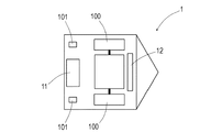
搬送車1は、図2のように、逆回転を含めて個別の回転制御か可能な左右の駆動輪100と、2つの自在車輪(フリーキャスター)101を備える移動体である。例えば左右の駆動輪100を逆向きに回転すれば、その場でのスピンターンにより搬送車1を回転できる。搬送車1の底面では、左右の駆動輪100の前側に当たる位置にセンサユニット12が取り付けられている。また、車体の内部には車両コントローラ11やバッテリ等が収容されている。
As shown in FIG. 2, the
図2及び図3のセンサユニット12は、磁気マーカである誘導マーカ5が発生する磁気を検出する検出センサである。センサユニット12では、図3に示すごとく、磁気検出素子(センサ)120が10mm間隔(センサ分解能:Sd)で横方向に8個配列されている。センサユニット12は、各磁気検出素子120の検出結果を1かゼロで表す8ビットの検出データを出力する。最下位のビットが進行方向に向かって右端の磁気検出素子120に対応し、最上位のビットが左端の磁気検出素子120に対応している。
The
図2の車両コントローラ11は、左右の駆動輪100を個別に回転制御する制御手段、センサユニット12の検出データを一定周期で取り込む検出データ取得手段、走行経路10Rに相対する自車の姿勢を表すデータを演算する演算手段、走行経路10Rを示すティーチデータ(教示データ)を記憶する手段等としての機能を備える制御ユニットである。
The
記憶する手段が記憶するティーチデータは、上記のように1つ目の誘導マーカ5A(図1参照。)を通過して2つ目の誘導マーカ5Bの設置位置で右に90度ターンする等、搬送車1の走行経路10Rを示す教示情報である。
演算手段は、センサユニット12が出力する上記の8ビットの検出データを取得すると共に、上記の制御手段による駆動輪100の回転角度から搬送車1の移動距離を計算し、走行経路10Rに相対する自車の姿勢を表すデータを演算する。自車の姿勢を表すデータとしては、経路方向に対する進行方向の角度的なずれ、及び車幅方向の位置的なずれであるオフセットがある。なお、演算方法については後で詳しく説明する。
The teach data stored by the storing means passes through the
The calculation means obtains the above 8-bit detection data output from the
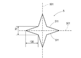
本例の移動体システム10では、誘導マーカ5の形状に技術的な特徴のひとつがある。誘導マーカ5は、図4のように、上下左右に向けて鋭角に突出する4箇所のテーパー形状(くさび形状)を有し全体として十字型の形状を呈している。4箇所のテーパー形状は全て同じ形状をなし、誘導マーカ5は、十字に直交する中心線501を介して上下左右に線対称の形状となっている。各テーパー形状の大きさは根元側の幅が70mm、突出長さが130mmであり、誘導マーカ5全体では、直径330mmの円に内接する大きさとなっている。
In the
誘導マーカ5は、上記の十字に直交する中心線501が走行経路10R(図1)の経路方向10Drに沿うように配置される(図5参照。)。したがって、搬送車1は、誘導マーカ5に接近する際にはテーパー形状の先端側から誘導マーカ5に進入し、誘導マーカ5を通過する際にはテーパー形状の先端側に離脱する。誘導マーカ5をテーパー状の外縁をなす辺のうち、テーパー形状をなして交差する直線的な2辺511は、上記の中心501上で交わると共に中心線501に対して同じ角度で斜行している。
The
車両コントローラ11(図2)の演算手段は、センサユニット12が出力する上記の8ビットの検出データを利用して、走行経路10Rに対する進行方向の角度的なずれ、走行経路に対する位置的なずれを演算する。この演算処理の内容について、図5を参照しながら説明する。
The calculation means of the vehicle controller 11 (FIG. 2) uses the above 8-bit detection data output from the
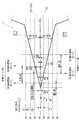
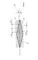
図5では、楽譜の五線譜のような8本の等間隔の横線を示している。この横線は、センサユニット12の各磁気検出素子120(S1〜S8)の軌跡を表している。以下の説明では、進行方向に向かって右端の磁気検出素子120をS1とし、左側に向けてS2、S3、S4・・・とする。図面中の右側から左側に食い込むように図示されたテーパー形状は誘導マーカ5の一部を示している。上記の通り、誘導マーカ5は、予定された走行経路10Rの経路方向10Drに対してテーパー形状の中心線501が沿うように設置されている。このような設置では、誘導マーカ5のテーパー形状の頂点が走行経路10R(経路方向10Dr)上に位置し、経路方向10Drに対して2辺511L、Rが同じ角度をなして斜行することになる。
FIG. 5 shows eight equally spaced horizontal lines such as a musical score. This horizontal line represents the locus of each magnetic detection element 120 (S1 to S8) of the
図5の例は、走行経路10Rの経路方向10Drに対して、搬送車1の矢印で図示する進行方向1Drが角度的に0.5度ずれているときの例である。
センサユニット12を構成する各磁気検出素子120は、誘導マーカ5のテーパー形状を形成する2辺511と、五線譜のような磁気検出素子120(S1〜S8)の軌跡と、の交点で誘導マーカ5の検出状態に切り替わる。演算手段は、各磁気検出素子120に対応するビットデータで構成される8ビットの検出データを取得し、各ビットのビットデータの0から1への立ち上がりにより検出状態への切り替わりを検知する。
The example of FIG. 5 is an example when the traveling direction 1Dr illustrated by the arrow of the
Each of the
搬送車1が誘導マーカ5に接近すると、テーパー形状をなす2辺511のうちの進行方向に向かって左側に位置する辺511Lが形成する左側テーパー部については、S5が一番最初に検出状態となり(0→1への立ち上がり)、次にS6が検出状態に切り替わる(0→1)。進行方向に向かって右側に位置する辺511Rが形成する右側テーパー部については、S4が一番最初に検出状態となり(0→1)、次にS3が検出状態に切り替わる(0→1)。
When the
演算手段は、上記のように左右の駆動輪100の回転角度から計算した移動距離を利用して各磁気検出素子120が検出状態に切り替わったときの位置を特定し、これにより以下の(1)〜(3)の各データを計測する。さらに、演算手段は、これらのデータを利用して以下(4)〜(11)の各データを演算する。
The calculation means uses the movement distance calculated from the rotation angle of the left and
(1)左側変化点間隔(DSL):左側テーパー部について、最初に磁気検出素子S5が検出した位置と、2番目に磁気検出素子S6が検出した位置と、の距離。同図中の丸囲み数字1の38.56mm。
(2)左右位相差(PhLR):左側テーパー部を最初に磁気検出素子S5が検出した位置と、右側テーパー部を最初に磁気検出素子S4が検出した位置と、の距離。同図中の丸囲み数字2の21.51mm。
(3)右側変化点間隔(DSR):右側テーパー部について、最初に磁気検出素子S4が検出した位置と、2番目に磁気検出素子S3が検出した位置と、の距離。同図中の丸囲み数字3の41.53mm。
(1) Left change point interval (DSL): The distance between the position detected by the magnetic detection element S5 first and the position detected by the magnetic detection element S6 second for the left tapered portion. The circled
(2) Left-right phase difference (PhLR): a distance between a position where the left taper portion is first detected by the magnetic detection element S5 and a position where the right taper portion is first detected by the magnetic detection element S4. The circled number 2 in the figure is 21.51 mm.
(3) Right change point interval (DSR): Distance between the position detected by the magnetic detection element S4 first and the position detected by the magnetic detection element S3 second for the right tapered portion. The circled
(4)左側角度(DegL):左側テーパー部をなす511L辺と、搬送車1の進行方向と、のなす角度。同図中の丸囲み数字4の角度。
DegL=arctan(Sd/DSL)=14.54度
(5)右側角度(DegR):右側テーパー部をなす辺511Rと、搬送車1の進行方向と、のなす角度。同図中の丸囲み数字5の角度。
DegR=arctan(Sd/DSR)=13.54度
(6)進行方向角度ずれ(DegOS):テーパー形状の中心線501(走行経路の経路方向10Drに一致。)に対する搬送車1の進行方向の角度的なずれ。同図中の丸囲み数字6の角度。
DegOS=|DegL−DegR|/2=0.5度
(7)計測開始点の右側交点オフセット(OFR):同図中の丸囲み数字7の位置的なずれ。
OFR=tan(DegR)×PhLR=5.18mm
(8)位相検出点の左側オフセット(OFL):同図中の丸囲み数字8の位置的なずれ。
OFL=tan(DegL)×PhLR
=tan(14.54)×21.51=5.58mm
(9)先端オフセット(OFTOP):同図中の丸囲み数字9の位置的なずれ。
OFTOP=(Sd−OFR)/(OFR+OFL)×OFL
=(10−5.18)/(5.18+5.58)×5.58=2.5mm
(10)マーカ先端位置(PoTOP):誘導マーカ5が検出された最先の位置と、誘導マーカ5の先端の位置と、の距離。同図中の丸囲み数字10の距離。
PoTOP=tan(90−DegL)×OFTOP
=tan(90−14.54)×2.5=9.64mm
(11)任意位置でのオフセット(OFSA):任意の進行方向の位置における車幅方向の位置的なずれ。
OFSA=tan(DegOS)×(PoTOP+任意の長さ)
例えばS6が検出状態に切り替わったときの位置でのオフセット(OFSA)は、同図中の丸囲み数字11の位置的なずれとなる。誘導マーカ5が検出された最先の位置と、磁気検出素子S6が検出状態に切り替わったときの位置と、の長さが38.56mmであるから、
OFSA=tan(0.5)×(9.64+38.56)=0.42mm
となる。
(4) Left angle (DegL): An angle formed between the 511L side forming the left tapered portion and the traveling direction of the
DegL = arctan (Sd / DSL) = 14.54 degrees (5) Right angle (DegR): An angle formed by the
DegR = arctan (Sd / DSR) = 13.54 degrees (6) Travel direction angle deviation (DegOS): Angle of travel direction of the
DegOS = | DegL−DegR | /2=0.5 degrees (7) Right intersection offset (OFR) of measurement start point: positional deviation of circled
OFR = tan (DegR) × PhLR = 5.18 mm
(8) Left offset (OFL) of the phase detection point: positional deviation of the circled numeral 8 in FIG.
OFL = tan (DegL) × PhLR
= Tan (14.54) × 21.51 = 5.58 mm
(9) Tip offset (OFTOP): Positional deviation of the circled numeral 9 in FIG.
OFTOP = (Sd−OFR) / (OFR + OFL) × OFL
= (10-5.18) / (5.18 + 5.58) × 5.58 = 2.5 mm
(10) Marker tip position (PoTOP): Distance between the earliest position where the
PoTOP = tan (90-DegL) × OFTOP
= Tan (90-14.54) × 2.5 = 9.64 mm
(11) Offset at an arbitrary position (OFSA): positional deviation in the vehicle width direction at an arbitrary position in the traveling direction.
OFSA = tan (DegOS) × (PoTOP + arbitrary length)
For example, the offset (OFSA) at the position when S6 is switched to the detection state is a positional deviation of the circled numeral 11 in FIG. Since the length of the earliest position where the
OFSA = tan (0.5) × (9.64 + 38.56) = 0.42 mm
It becomes.
以上のように図4のテーパー形状を備える誘導マーカ5を採用すれば、センサユニット12を利用して進行方向の角度的なずれや、車幅方向の位置的なずれを搬送車1側で演算可能となる。車幅方向に磁気検出素子120が配列されたセンサユニット12は、磁気テープや磁気マーカ等を追従する搬送車1が通常、備えるセンサである。この誘導マーカ5を採用した移動体システム10であれば、センサユニット12のほかに新たなセンサを追加することなく、進行方向の角度的なずれや車幅方向の位置的なずれを演算等できるようになり、コスト的に非常に有利である。
If the
誘導マーカ5として、磁気マーカを例示したが、色や反射率などにより光学的に検出可能なマーカであっても良いし、電磁気的に検出可能なマーカであっても良い。センサユニットがマーカを検出する原理はどのような原理であっても良い。センサユニットの車幅方向において間隔を空けて配列された複数のセンサが個別に検出できるマーカであれば良い。センサユニットを構成するセンサについても磁気検出素子に限定されず、誘導マーカの検出原理に対応するセンサを採用すれば良い。
Although the magnetic marker is exemplified as the
誘導マーカの形状については、図4の十字形状には限定されない。例えば、図5に例示するように、走行経路10Rの経路方向に沿って対角線が位置するように45度傾けた正方形等であっても良い。搬送車1が直進する誘導マーカであれば両側にテーパー形状を持つ菱形であっても良い。
テーパー形状の頂角の角度として図4では鋭角を例示したが、図5に例示する直角であっても良く、90度を超える鈍角であっても良い。
The shape of the guide marker is not limited to the cross shape in FIG. For example, as illustrated in FIG. 5, it may be a square inclined 45 degrees so that a diagonal line is positioned along the route direction of the
Although the acute angle is illustrated in FIG. 4 as the apex angle of the taper shape, it may be a right angle illustrated in FIG. 5 or an obtuse angle exceeding 90 degrees.
(実施例2)
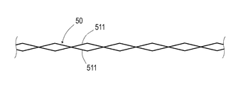
本例は、菱形が連なる誘導テープ50を採用した移動体システムの例である。この内容について、図7〜図9を参照して説明する。
図7の誘導テープ50は、菱形が連なる磁気テープであり、各菱形の両側にはテーパー形状が形成されている。この誘導テープ50を採用した移動体システムでは、搬送車の進行方向の角度的なずれを早期に検出可能である。
(Example 2)
This example is an example of a mobile system that employs a
The
図8及び図9では、走行経路の経路方向10Drに沿うように配設された誘導テープ50の中心線501に対して、搬送車の進行方向1Drが2度ずれている場合のセンサユニットの検出データを例示している。これらの図では、センサユニットとして車幅方向に配列された8つの磁気検出センサによる時間毎の検出位置が、板チョコのブロックのように図示されている。各ブロックのうち、白抜きのブロックが非検出状態の検出位置を示し、ハッチングのブロックが検出状態の検出位置を示している。
8 and 9, the sensor unit detects when the traveling direction 1Dr of the transport vehicle is shifted by 2 degrees with respect to the
図8の誘導テープ50の場合であれば、進行方向に向かって左側の左側テーパー部では、検出状態の磁気検出素子が1個増減するのに42.27mmの移動を要し、右側テーパー部では61mmの移動を要している。一方、図9に参考例として例示するテープ幅が一定の誘導テープ(磁気テープ)9の場合には、検出状態の磁気検出素子が1個増減するのに283.36mmの移動が必要となっている。
In the case of the
つまり、図7及び図8の菱形が連なる誘導テープ50の場合であれば、実施例1で説明した演算により100mmに満たない移動距離の範囲内で搬送車の進行方向の角度的なずれを演算あるいは検出できる。一方、図9の参考例の誘導テープ9の場合には、搬送車の進行方向の角度的なずれを検出するために最低283.36mmの移動を要する。
That is, in the case of the
このように、本例の図7及び図8の誘導テープ50を採用すれば、搬送車の進行方向のずれを早期に検出できる。制御上では、搬送車の進行方向を制御するための制御上のムダ時間が少なくなるため、制御性を向上できる。
なお、その他の構成及び作用効果については、実施例1と同様である。
Thus, if the
Other configurations and operational effects are the same as those in the first embodiment.
以上、実施例のごとく本発明の具体例を詳細に説明したが、これらの具体例は、特許請求の範囲に包含される技術の一例を開示しているにすぎない。言うまでもなく、具体例の構成や数値等によって、特許請求の範囲が限定的に解釈されるべきではない。特許請求の範囲は、公知技術や当業者の知識等を利用して前記具体例を多様に変形、変更あるいは適宜組み合わせた技術を包含している。 As described above, specific examples of the present invention have been described in detail as in the embodiments. However, these specific examples merely disclose an example of the technology included in the scope of claims. Needless to say, the scope of the claims should not be construed as limited by the configuration, numerical values, or the like of the specific examples. The scope of the claims includes techniques in which the specific examples are variously modified, changed, or appropriately combined using known techniques and knowledge of those skilled in the art.
1 搬送車(移動体)
1Dr 進行方向
10 移動体システム
10R 走行経路
10Dr 経路方向
11 車両コントローラ(演算手段)
12 センサユニット
120 磁気検出素子
5 誘導マーカ(磁気マーカ)
50 誘導テープ
501 中心線
511 辺
1 Transport vehicle (moving body)
12
50
Claims (4)
当該誘導マーカの外縁をなす辺の中には、テーパー形状の頂点を形成して交わる直線的な2辺が含まれており、
前記走行経路上に前記テーパー形状の頂点が位置すると共に、前記走行経路の経路方向に対して前記直線的な2辺が同じ角度で斜行するように配置可能な誘導マーカ。 A plurality of sensors are arranged along a travel route planned to guide a moving body including a sensor unit arranged in the vehicle width direction at a predetermined interval, and each sensor constituting the sensor unit is individually A detectable guidance marker,
The sides forming the outer edge of the guide marker include two straight sides that intersect to form a tapered apex,
A guide marker that can be arranged such that the apex of the tapered shape is located on the travel route and the two straight sides are inclined at the same angle with respect to the route direction of the travel route.
前記誘導マーカが、請求項1〜3のいずれか1項に記載された誘導マーカであって、
前記移動体は、前記センサユニットの各センサによる前記誘導マーカの検出結果を取得して、前記走行経路の経路方向に対する進行方向の角度的なずれ、及び前記走行経路に対する前記移動体の車幅方向の位置的なずれを演算する演算手段を備えている移動体システム。 A plurality of sensors are arranged along the travel path to guide a moving body having a sensor unit arranged in the vehicle width direction at a predetermined interval, and each sensor constituting the sensor unit can be individually detected. A mobile system including a guidance marker,
The guidance marker is the guidance marker described in any one of claims 1 to 3,
The moving body acquires the detection result of the guidance marker by each sensor of the sensor unit, and the angular deviation of the traveling direction with respect to the route direction of the traveling route, and the vehicle width direction of the moving body with respect to the traveling route A mobile system comprising a computing means for computing the positional deviation of.
Priority Applications (1)
| Application Number | Priority Date | Filing Date | Title |
|---|---|---|---|
| JP2016043178A JP2017161970A (en) | 2016-03-07 | 2016-03-07 | Guide marker and mobile body system |
Applications Claiming Priority (1)
| Application Number | Priority Date | Filing Date | Title |
|---|---|---|---|
| JP2016043178A JP2017161970A (en) | 2016-03-07 | 2016-03-07 | Guide marker and mobile body system |
Publications (1)
| Publication Number | Publication Date |
|---|---|
| JP2017161970A true JP2017161970A (en) | 2017-09-14 |
Family
ID=59858000
Family Applications (1)
| Application Number | Title | Priority Date | Filing Date |
|---|---|---|---|
| JP2016043178A Pending JP2017161970A (en) | 2016-03-07 | 2016-03-07 | Guide marker and mobile body system |
Country Status (1)
| Country | Link |
|---|---|
| JP (1) | JP2017161970A (en) |
Cited By (1)
| Publication number | Priority date | Publication date | Assignee | Title |
|---|---|---|---|---|
| JP2023080729A (en) * | 2021-11-30 | 2023-06-09 | 村田機械株式会社 | Traveling vehicle system and marker deviation detection method |
-
2016
- 2016-03-07 JP JP2016043178A patent/JP2017161970A/en active Pending
Cited By (2)
| Publication number | Priority date | Publication date | Assignee | Title |
|---|---|---|---|---|
| JP2023080729A (en) * | 2021-11-30 | 2023-06-09 | 村田機械株式会社 | Traveling vehicle system and marker deviation detection method |
| JP7682444B2 (en) | 2021-11-30 | 2025-05-26 | 村田機械株式会社 | Traveling vehicle system and method for detecting deviation of marker |
Similar Documents
| Publication | Publication Date | Title |
|---|---|---|
| CA2824189C (en) | Automatic guided vehicle system and method | |
| US20190079537A1 (en) | Automatic guided vehicle | |
| JP4910219B2 (en) | Autonomous moving method and autonomous moving body | |
| TWI400590B (en) | Mobile system | |
| CN201993114U (en) | Magnetic navigation sensor | |
| TWI445591B (en) | Mobile device and moving body position detection method | |
| WO2010150580A1 (en) | Travel control device for unmanned conveyance vehicle | |
| CN109478066A (en) | Mobile robot and control method | |
| JP2018177002A (en) | Unmanned transport truck | |
| JP2017161970A (en) | Guide marker and mobile body system | |
| US11016502B1 (en) | Autonomous travel system | |
| JP2007219960A (en) | Position deviation detection device | |
| JP2007213356A (en) | Automated guided facility | |
| JP2009294980A (en) | Running vehicle and running vehicle system | |
| US20210141388A1 (en) | Autonomous travel device and autonomous travel system | |
| JP5077567B2 (en) | Route correction system for automated guided vehicles | |
| JPS62109105A (en) | Magnetic guidance method for vehicle | |
| JP6085063B1 (en) | Sensor arrangement structure for self-propelled transport vehicles | |
| JP3846828B2 (en) | Steering angle control device for moving body | |
| JP2012216129A (en) | Unmanned vehicle and unmanned carrier system | |
| JP5390360B2 (en) | Automated guided vehicle | |
| JPH02236707A (en) | Travel controller for unmanned vehicle | |
| JP2005322155A (en) | Position detection device and transportation system | |
| JPS61166608A (en) | Position detecting method of unmanned truck | |
| KR20090084219A (en) | Electromagnetic Guidance Mobile Robot Path Tracking System |