JP2017161392A - Observation tower - Google Patents
Observation tower Download PDFInfo
- Publication number
- JP2017161392A JP2017161392A JP2016046871A JP2016046871A JP2017161392A JP 2017161392 A JP2017161392 A JP 2017161392A JP 2016046871 A JP2016046871 A JP 2016046871A JP 2016046871 A JP2016046871 A JP 2016046871A JP 2017161392 A JP2017161392 A JP 2017161392A
- Authority
- JP
- Japan
- Prior art keywords
- boom
- observation tower
- tower according
- tip
- main
- Prior art date
- Legal status (The legal status is an assumption and is not a legal conclusion. Google has not performed a legal analysis and makes no representation as to the accuracy of the status listed.)
- Granted
Links
Images


Classifications
-
- Y—GENERAL TAGGING OF NEW TECHNOLOGICAL DEVELOPMENTS; GENERAL TAGGING OF CROSS-SECTIONAL TECHNOLOGIES SPANNING OVER SEVERAL SECTIONS OF THE IPC; TECHNICAL SUBJECTS COVERED BY FORMER USPC CROSS-REFERENCE ART COLLECTIONS [XRACs] AND DIGESTS
- Y02—TECHNOLOGIES OR APPLICATIONS FOR MITIGATION OR ADAPTATION AGAINST CLIMATE CHANGE
- Y02E—REDUCTION OF GREENHOUSE GAS [GHG] EMISSIONS, RELATED TO ENERGY GENERATION, TRANSMISSION OR DISTRIBUTION
- Y02E10/00—Energy generation through renewable energy sources
- Y02E10/70—Wind energy
- Y02E10/728—Onshore wind turbines
Abstract
Description
本発明は、気象データの計測を行う観測塔に関する。 The present invention relates to an observation tower that measures meteorological data.
現在、洋上に風力発電設備を設置するケースが増えており、その設置環境の選定や発電能力試算のため、予め洋上にて風向、風速などの風況観測を行うニーズが高まっている。 Currently, there are an increasing number of cases where wind power generation facilities are installed on the ocean, and there is an increasing need to observe wind conditions such as wind direction and wind speed in advance in order to select the installation environment and estimate the power generation capacity.
従来、風力発電設備は陸上に設けるのが一般的であり、上記の風況観測は、地上に観測塔を設け、これに各種の計測機器を取付けて行うことが多い。観測塔は、地上に設けた主柱を支線によって地上から姿勢保持して構成されることが多く、この主柱から細径のパイプを水平に張り出させ、主柱から離れたパイプ先端に風速計や風向計などの計測機器を設置して計測を行う方法が一般的である。これにより、風況に対する主柱やパイプの影響を小さくし、計測精度を確保することができる。 Conventionally, wind power generation facilities are generally provided on land, and the above wind condition observation is often performed by providing an observation tower on the ground and attaching various measuring devices to the observation tower. Observation towers are often constructed by holding the main pillar on the ground with a branch line from the ground, and a small-diameter pipe is projected horizontally from the main pillar, and the wind speed at the tip of the pipe away from the main pillar A method of measuring by installing a measuring instrument such as a gauge or an anemometer is common. Thereby, the influence of the main pillar and the pipe on the wind condition can be reduced, and the measurement accuracy can be ensured.
一方、洋上においては特許文献1のように浮体式のプラットホームに設置したドップラー式の風況計測装置により風向や風速のデータを計測する例がある。ドップラー式の風況計測装置は、上空に向けて音波などのビームを放射し、大気からの反射波を受信してその周波数のシフト量から遠隔にある大気の風向や風速を計測するものである。
On the other hand, on the ocean, there is an example in which wind direction and wind speed data is measured by a Doppler type wind condition measuring device installed on a floating platform as in
特許文献1のようにドップラー式の風況計測装置を用いる場合、雨や霧など天候の影響により計測精度が低下したり、風況計測装置に波が被ったりする問題があり、洋上における風況観測の方法が一般化されるには至っていない。
When using a Doppler-type wind condition measuring device as in
計測精度の面からは、前記のように観測塔に計測機器を設け、その設置位置での風況のデータを直接計測することが望ましい。しかしながら、洋上において陸上の場合と同様に主柱を支線で姿勢保持するのはスペース上、構造上の問題から非常に困難である。 From the viewpoint of measurement accuracy, it is desirable to provide measurement equipment in the observation tower as described above and directly measure wind condition data at the installation position. However, it is very difficult to maintain the posture of the main column with the branch line on the ocean because of space and structural problems as in the case of land.
主柱の強度を高めて自立可能な剛構造とすれば支線は不要となるものの、主柱の幅や構成部材が大きくなると主柱周りの広範囲の風況に影響を与える。結果、計測機器を主柱からより遠い位置に取付ける必要が生じる。 Although a branch line is not required if the main column is strengthened to be self-supporting and have a rigid structure, an increase in the width and components of the main column affects a wide range of wind conditions around the main column. As a result, it is necessary to mount the measuring device at a position farther from the main column.
そのために例えば主柱から長いブームを張り出させて先端に計測機器を取付ける構成とする場合、ブームは高剛性な構造にしなければならず、ブームが大きくなることで風況に与える影響が大となり計測精度に悪影響がでる。加えて、ブームが長くマッシブな構造になると、風による共振が発生しやすくなり、計測機器が振動することによって計測精度が低下する恐れもある。 For this reason, for example, when a long boom is extended from the main pillar and a measuring device is attached to the tip, the boom must have a highly rigid structure. Measurement accuracy is adversely affected. In addition, if the boom is long and has a massive structure, resonance due to wind is likely to occur, and the measurement accuracy may be reduced due to vibration of the measurement device.
本発明は上記の問題に鑑みてなされたものであり、水上において好適に気象データを計測できる観測塔を提供することを目的とする。 This invention is made | formed in view of said problem, and it aims at providing the observation tower which can measure meteorological data suitably on the water.
前述した課題を解決するための本発明は、水上にて気象データの計測を行うための観測塔であって、主柱と、主柱から側方に延び、長手方向と直交する方向の断面が扁平状であるブーム本体を有するブームと、ブーム先端に設けられた、気象データを計測するための計測機器と、を有することを特徴とする観測塔である。 The present invention for solving the above-described problems is an observation tower for measuring meteorological data on the water, and has a main column and a cross section extending in a direction perpendicular to the longitudinal direction extending laterally from the main column. An observation tower comprising: a boom having a flat boom body; and a measuring device for measuring meteorological data provided at the tip of the boom.
本発明に係る観測塔では、上記のブーム構造により、ブームの風に対する見付面積を小さくしつつ、ブームに必要な剛性を確保できるようになる。このような新しいブーム構造を採用することで、主柱の影響を小さくするためのブーム長を確保しながら、ブームが風況等に与える影響や風によるブームの振動を抑えることが可能となり、高い精度で風況等の気象データを計測することが可能になる。 In the observation tower according to the present invention, the boom structure described above makes it possible to secure the necessary rigidity for the boom while reducing the area of the boom that is found with respect to the wind. By adopting such a new boom structure, it is possible to suppress the influence of the boom on the wind condition and the vibration of the boom due to the wind while securing the boom length to reduce the influence of the main pillar. It becomes possible to measure weather data such as wind conditions with accuracy.
前記ブーム本体は、長手方向に沿った一対の主桁の間に床版が配置された構成を有することが望ましい。また前記床版は、上下方向に貫通する孔を有することが望ましい。
このようなブーム本体の構成により、簡易な構造で剛性を好適に確保することができる。またブーム上を歩いて渡ることができ、ブーム先端の計測機器等のメンテナンスが容易になる。さらに、床版が上下方向の孔を有することで床版の上下の気圧が同等となり、ブーム本体の風による振動を防止することができる。
The boom body preferably has a configuration in which a floor slab is disposed between a pair of main girders along the longitudinal direction. The floor slab preferably has a hole penetrating in the vertical direction.
With such a configuration of the boom body, it is possible to suitably ensure rigidity with a simple structure. In addition, it is possible to walk on the boom, and maintenance of the measuring instrument at the tip of the boom becomes easy. Furthermore, since the floor slab has holes in the vertical direction, the upper and lower air pressures of the floor slab become equal, and vibration of the boom body due to wind can be prevented.
前記計測機器は、例えば気象データとして風況のデータを計測する。
計測機器によって風向や風速など風の状態を示す風況のデータを計測することで、計測結果を風力発電設備の設置環境の選定や発電能力試算に利用することができる。
The measuring device measures wind condition data as weather data, for example.
By measuring wind condition data indicating wind conditions such as wind direction and wind speed with a measuring device, the measurement results can be used for selecting the installation environment of the wind power generation facility and for calculating the power generation capacity.
前記ブームが、前記主柱から架け渡された線材により保持されることが望ましい。また前記線材は、前記ブームの上下両側に設けられることが望ましい。
ブームを主柱から線材によって保持することでブームの変形を防止することができ、線材によって上下両側からブームを保持することで、ブームの上下の振動を防止できる。
It is desirable that the boom is held by a wire rod that extends from the main pillar. Moreover, it is desirable that the wire is provided on both upper and lower sides of the boom.
The boom can be prevented from being deformed by holding the boom from the main pillar with the wire, and the boom can be prevented from vibrating up and down by holding the boom from both the upper and lower sides with the wire.
前記主柱は、3本の脚柱の間に水平材が設けられた略三角形平面を有することが望ましい。
これにより、脚柱の本数を最小限にして主柱が風況に与える影響を低減することができる。
The main column preferably has a substantially triangular plane in which a horizontal member is provided between three leg columns.
Thereby, the influence which a main pillar has on a wind condition can be reduced by minimizing the number of pedestals.
前記主柱は、上下の水平材の間に斜材が設けられたトラス構造を有することが望ましい。
主柱としてトラス構造を採用することで、風況に与える影響を小さくしつつ高強度とできる。
The main pillar preferably has a truss structure in which diagonal members are provided between upper and lower horizontal members.
By adopting a truss structure as the main pillar, it is possible to achieve high strength while reducing the effect on the wind conditions.
前記ブーム先端は前記ブーム本体側へと折り返し可能であることが望ましい。
これにより、ブーム先端に設けた計測機器等のメンテナンスが容易になる。
It is desirable that the boom tip can be folded back toward the boom body.
This facilitates maintenance of the measuring instrument provided at the boom tip.
前記ブームに、作業員の墜落防止用のレールが設けられることが望ましい。
例えばレールに作業員の安全帯をロープ等を介して接続することで、作業員の墜落を防止することができる。
It is desirable that a rail for preventing a worker from falling is provided on the boom.
For example, the worker's crash can be prevented by connecting the worker's safety belt to the rail via a rope or the like.
前記ブーム先端は、複数の前記計測機器が取付けられた計測機器取付部を有することが望ましい。
これにより、風向と風速など複数種類のデータを1箇所のブーム先端にて好適に計測できる。
It is desirable that the boom tip has a measuring device mounting portion to which a plurality of the measuring devices are mounted.
Thereby, a plurality of types of data such as wind direction and wind speed can be suitably measured at one boom tip.
本発明により、水上において好適に気象データを計測できる観測塔を提供することができる。 According to the present invention, it is possible to provide an observation tower capable of measuring meteorological data suitably on the water.
以下、図面に基づいて本発明の好適な実施形態について詳細に説明する。 Hereinafter, preferred embodiments of the present invention will be described in detail with reference to the drawings.
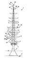
図1は本発明の実施形態に係る観測塔1の概略を示す図であり、観測塔1の正面を見たものである。本実施形態に係る観測塔1は、海洋などの水上に設けられ、気象データとして、風向、風速など風の状態を示す風況のデータを計測するためのものである。
FIG. 1 is a diagram showing an outline of an
観測塔1は、水底の地盤5に基部4を設け、その上に床状のプラットホーム2を設置し、このプラットホーム2に主柱10を設けたものである。主柱10にはブーム20が設けられ、ブーム先端に風況のデータを計測するための計測機器40が設けられる。
The
主柱10は鋼材によって構成された塔状構造物であり、水平材11、斜材12、脚柱13等を有する。主柱10は、外周部に配置された上下の水平材11の間に斜材12が略ハの字状に設けられたトラス構造を有し、このトラス構造を隣り合う脚柱13の間で上下に積層して構成される。
The
主柱10は頂部に行くにつれ幅の狭まった形状となっており、脚柱13同士の間隔も主柱10の頂部に行くにつれ狭まる。主柱10の頂部には避雷針50や航空障害灯60なども設けられる。
The
図2(a)は図1の線A−Aによる主柱10の水平方向断面を示す図である。図2(a)に示すように、主柱10は、3本の脚柱13の間に水平材11が設けられた略三角形平面を有する。特に本実施形態では主柱10の平面が略正三角形状であり、この平面もまた、水平材11を略三角形状に組み合わせたトラス構造を有する。
FIG. 2A is a diagram showing a horizontal cross section of the
図1に示すように、ブーム20は、主柱10から側方へと水平に延びるように設けられる。ブーム20は主柱10から架け渡されたワイヤ30(線材)によって姿勢が保持され、これによりブーム20の変形が防止される。ワイヤ30はブーム20の上下両側に設けられ、ワイヤ30によって上下からブーム20を保持することで、ブーム20の上下の振動が防止される。
As shown in FIG. 1, the
図2(b)は図1の線B−Bによる主柱10の水平方向断面を示す図である。図2(b)に示すように、ブーム20は、主柱10の略三角形平面の各々の辺の中央部に当たる位置から、当該辺と直交する方向へと側方に延びている。ワイヤ30は、主柱10の略三角形平面の各々の辺の両端部(略三角形平面の頂点)から当該辺に設けたブーム20へと架け渡されており、ブーム20はワイヤ30により左右からも保持される。
FIG. 2B is a diagram showing a horizontal cross section of the
なお、図1では、煩雑さを避けるため、観測塔1の正面側(図2(b)の下側に対応する)のブーム20および当該ブーム20を保持するワイヤ30などの図示を省略している。また主柱10においてブーム20の高さに対応する位置では、水平材11の上方に歩廊14が設けられる。歩廊14としてはグレーチングなどが用いられ、作業員はこの歩廊14からブーム20上にアクセスできる。
In FIG. 1, in order to avoid complication, the illustration of the
ブーム20は鋼材によって片持ち梁状に構成される。ブーム20の長さは主柱10の平面の大きさ等に応じて定められ、一般的には主柱10の平面が大きいほどブーム20を長くする。またブーム20は共振や風による渦励振が生じないように設計される。ブーム20あるいは前記の主柱10に用いる鋼材は特に限定されず、例えばステンレス鋼などの耐食性の高いものを用いたり、防食塗装を施したりすることもできる。
The
ブーム20はブーム本体21とブーム先端22から構成される。前記のワイヤ30はブーム本体21に取付けられ、ブーム先端22には前記したように計測機器40が設けられる。
The
図3はブーム本体21を示す図である。図3(a)はブーム本体21を上から見た図であり、図3(b)はブーム本体21を側方から見た図である。
FIG. 3 is a view showing the boom
図3(a)に示すように、ブーム本体21は、フレーム211に床版212を取付けて構成される。
As shown in FIG. 3A, the
フレーム211は、平面が略梯子状となるように鋼材を組み合わせたものである。図4は床版212を省略してフレーム211を示した図である。図4に示すように、フレーム211は、長手方向に沿った一対の主桁211aの間に横架材211bを設けて構成される。
The
床版212はフレーム211の開口部に配置される。床版212は、上下方向に貫通する孔を通気のために有し、そのような部材として本実施形態ではグレーチングが用いられる。
The
図3(a)、(b)に示すように、フレーム211の両側面にはプレート213が設けられる。ワイヤ30の先端はこのプレート213に取付けられる。
As shown in FIGS. 3A and 3B,
なお、本実施形態のブーム20では、作業員の墜落防止用のレール24がブーム本体21の一方の側部に設けられる。レール24は支柱241により支持してブーム本体21の長手方向に沿って配置されており、このレール24に作業員の安全帯をロープ等を介してロリップ機構により接続することで、作業員の墜落が防止できる。このレール24は手摺としても利用可能である。
In the
図5はブーム本体21の長手方向と直交する方向の断面を示す図であり、図3(b)の線C−Cによる断面を見たものである。図5に示すように、ブーム本体21は、フレーム211の一対の主桁211aの間に床版212が配置された扁平状の断面構成を有する。すなわち、ブーム本体21の長手方向と直交する方向の断面を見たときに、厚さより幅の大きい扁平な形状となっている。ブーム本体21の幅は、例えばブーム本体21の厚さの4〜5倍程度か、あるいはそれ以上である。なお図5ではレール24等の図示を省略している。
FIG. 5 is a view showing a cross section in a direction orthogonal to the longitudinal direction of the boom
このようなブーム構造により、風に対する見付面積を小さくしつつ、ブーム20に必要な剛性を確保できる。また床版212を、グレーチングなど上下方向に貫通する孔を有するものとすることで、床版212の上下の気圧が同等となり、ブーム本体21の風による振動を防止することができる。
With such a boom structure, the rigidity required for the
図6はブーム先端22を示す図である。図6(a)はブーム先端22を上から見た図であり、図6(b)はブーム先端22を側方から見た図である。
FIG. 6 is a view showing the
ブーム先端22は、ブーム本体21に続けて配置されたフレーム221の先端に、計測機器取付部222を設けて構成される。フレーム221や計測機器取付部222は、鋼材として丸形鋼管や角形鋼管など細幅(例えば幅が25〜50mm程度)の棒材を用いて構成され、これにより風況に与える影響を小さくすることができる。
The
フレーム221は、平面が略梯子状となるように角形鋼管などを組み合わせたものである。フレーム221はヒンジ機構23によりブーム本体21のフレーム211に連結される。ブーム先端22をヒンジ軸を中心として鉛直面内で回転させることにより(図6(b)の矢印D参照)、ブーム先端22をブーム本体21側に折り返し可能である。これにより、ブーム本体21上の作業員によってブーム先端22の計測機器40のメンテナンスを容易に行うことができる。
The
フレーム221には略90度の中心角を有する円弧状のストッパ223が設けられており、ブーム先端22をブーム本体21側へと回転させる際に、ストッパ223の先端のプレート223aがブーム本体21のフレーム211に当接すると回転が停止するようになっている。
The
図7は計測機器取付部222を示す図である。図7は計測機器取付部222を正面から見たものであり、図6(a)、(b)を左側から見た図に対応する。
FIG. 7 is a view showing the measuring
計測機器取付部222は、水平材222aの両端部から上方へと鉛直材222bを設けるとともに、水平材222aの中央部から下方へと鉛直材222cを設けたものである。水平材222aは中央部付近で前記のフレーム221に固定される。水平材222aや鉛直材222b、222cには丸形鋼管などが用いられる。
The measuring
計測機器取付部222には複数の計測機器40が取付けられる。すなわち、計測機器取付部222の両鉛直材222bの先端付近、および鉛直材222cの先端付近のそれぞれに計測機器40が取付けられる。
A plurality of
本実施形態では、上記した両鉛直材222bのうち一方の鉛直材222bの先端付近に矢羽根式風向計などの風向計が取付けられ、他方の鉛直材222bの先端付近に三杯式風速計などの風速計が取付けられる。また鉛直材222cの先端付近にも、計測機器40として例えば三次元超音波風速計などの風速計が取付けられる。ただし、場所によっては計測機器取付部222において鉛直材222c及びその先端の計測機器40を省略することもある。
In the present embodiment, an anemometer such as an arrow vane type anemometer is attached near the tip of one of the
本実施形態では、これらの計測機器40によって気象データとして風向や風速など風況のデータが計測される。しかしながら、計測機器40はこれに限らず、例えば気象データとして、気圧、温度や湿度、雨量などを計測するための計測機器40を取付けてもよい。また、主柱10から延ばした3本のブーム20の先端に設けた計測機器40の計測データを補完することで、主柱10の周囲360度に渡るデータを作成することも可能である。
In the present embodiment, these
以上説明したように、本実施形態の観測塔1によれば、図5等で説明したブーム構造により、ブーム20の風に対する見付面積を小さくしつつ、ブーム20に必要な剛性を確保できるようになる。このような新しいブーム構造を採用することで、主柱10の影響を小さくするためのブーム長を確保しながら、ブーム20が風況等に与える影響や風によるブーム20の振動を抑えることが可能となり、高い精度で風況等の気象データを計測することが可能になる。
As described above, according to the
またブーム本体21は、長手方向に沿った一対の主桁211aの間に床版212を配置した構成を有することで、簡易な構造で剛性を好適に確保することができる。また作業員がブーム20上を歩いて渡ることができ、ブーム先端22の計測機器40等のメンテナンスを容易に行うことができる。さらに、床版212が上下方向の孔を有することで床版212の上下の気圧が同等となり、ブーム本体21の風による振動を防止することができる。
Moreover, the boom
また、計測機器40によって風向や風速など風の状態を示す風況のデータを気象データとして計測することで、計測結果を水上の風力発電設備の設置環境の選定や発電能力試算に利用することができる。
Moreover, by measuring wind condition data indicating wind conditions, such as wind direction and wind speed, as meteorological data using the measuring
さらに、ブーム20を主柱10からワイヤ30によって保持することでブーム20の変形を防止することができ、ワイヤ30によって上下両側からブーム20を保持することで、ブーム20の上下の振動を防止できる。
Furthermore, deformation of the
また、主柱10は、3本の脚柱13の間に水平材11を設けた略三角形平面とすることで、脚柱13の本数を最小限にして主柱10が風況に与える影響を低減することができる。また主柱10として上下の水平材11の間に斜材12を設けたトラス構造を採用することで、風況に与える影響を小さくしつつ高強度とでき、耐震性も確保できる。
Moreover, the
また、ブーム先端22をブーム本体21側に折り返し可能とすることで、ブーム先端22に設けた計測機器40等のメンテナンスが容易になる。
In addition, since the
さらに、ブーム20に設けたレール24に作業員の安全帯をロープ等を介して接続するなどして、作業員の墜落を防止することができる。
Furthermore, a worker's fall can be prevented by connecting a worker's safety belt to the
加えて、ブーム先端22の計測機器取付部222に複数の計測機器40を取付けることで、風向と風速など複数種類のデータを1箇所のブーム先端22にて好適に計測できる。
In addition, by attaching a plurality of measuring
しかしながら、本発明はこれに限らない。例えば主柱10の構成は前記したものに限らず、略正方形状の平面とすることも可能であるし、トラス構造でなくともよい。しかしながら、前記した構成とすることで、主柱10が風況に与える影響を極力低減しつつ、強度や耐震性を確保できる利点がある。
However, the present invention is not limited to this. For example, the configuration of the
同様に、ブーム20の構成も前記したものに限定されない。例えばブーム本体21は長手方向と直交する方向の断面を見たときに扁平な形状であればよく、その構造等は様々に考えられる。またブーム先端22の計測機器取付部222の構成や計測機器40の取付位置なども図7の例に限定されず、計測精度等を考慮して適宜定めることができる。例えば図7では両鉛直材222bの長さが異なっているが、これらの鉛直材222bの長さは特に限定されない。
Similarly, the configuration of the
また、観測塔1は、本実施形態のように水底の地盤5上に基部4を設けた着床式のものに限らず、観測塔1の大きさ等によっては浮体のプラットホーム上に主柱10等を設けた浮体式のものでもよい。ただし、この場合は波による揺れを考慮した計測データの補正が必要になる可能性がある。
Further, the
また、ワイヤ30の代わりに、その他の線材として鋼棒やケーブルによってブーム20を保持することも可能である。さらに、床版212もグレーチングに限らず、上下方向に貫通する孔を有していればよい。例えばパンチングメタルのような板材を用いることも可能である。
Moreover, it is also possible to hold the
以上、添付図面を参照して、本発明の好適な実施形態について説明したが、本発明は係る例に限定されない。当業者であれば、本願で開示した技術的思想の範疇内において、各種の変更例または修正例に想到し得ることは明らかであり、それらについても当然に本発明の技術的範囲に属するものと了解される。 The preferred embodiments of the present invention have been described above with reference to the accompanying drawings, but the present invention is not limited to such examples. It will be apparent to those skilled in the art that various changes or modifications can be conceived within the scope of the technical idea disclosed in the present application, and these are naturally within the technical scope of the present invention. Understood.
1:観測塔
2:プラットホーム
4:基部
5:地盤
10:主柱
11、222a:水平材
12:斜材
13:脚柱
14:歩廊
20:ブーム
21:ブーム本体
22:ブーム先端
23:ヒンジ機構
24:レール
30:ワイヤ
40:計測機器
50:避雷針
60:航空障害灯
211、221:フレーム
211a:主桁
211b:横架材
212:床版
222:計測機器取付部
222b、222c:鉛直材
223:ストッパ
1: Observation tower 2: Platform 4: Base 5: Ground 10:
Claims (11)
主柱と、
主柱から側方に延び、長手方向と直交する方向の断面が扁平状であるブーム本体を有するブームと、
ブーム先端に設けられた、気象データを計測するための計測機器と、
を有することを特徴とする観測塔。 An observation tower for measuring meteorological data on the water,
The main pillar,
A boom having a boom body extending laterally from the main pillar and having a flat cross section in a direction perpendicular to the longitudinal direction;
Measuring equipment for measuring weather data provided at the tip of the boom,
An observation tower characterized by comprising:
Priority Applications (1)
| Application Number | Priority Date | Filing Date | Title |
|---|---|---|---|
| JP2016046871A JP6617060B2 (en) | 2016-03-10 | 2016-03-10 | Observation tower |
Applications Claiming Priority (1)
| Application Number | Priority Date | Filing Date | Title |
|---|---|---|---|
| JP2016046871A JP6617060B2 (en) | 2016-03-10 | 2016-03-10 | Observation tower |
Publications (2)
| Publication Number | Publication Date |
|---|---|
| JP2017161392A true JP2017161392A (en) | 2017-09-14 |
| JP6617060B2 JP6617060B2 (en) | 2019-12-04 |
Family
ID=59853082
Family Applications (1)
| Application Number | Title | Priority Date | Filing Date |
|---|---|---|---|
| JP2016046871A Active JP6617060B2 (en) | 2016-03-10 | 2016-03-10 | Observation tower |
Country Status (1)
| Country | Link |
|---|---|
| JP (1) | JP6617060B2 (en) |
Cited By (2)
| Publication number | Priority date | Publication date | Assignee | Title |
|---|---|---|---|---|
| CN108919381A (en) * | 2018-05-18 | 2018-11-30 | 云南电网有限责任公司电力科学研究院 | A kind of meteorologic parameter detection device applied to electric power tower |
| KR102500311B1 (en) * | 2021-11-30 | 2023-02-14 | 제주대학교 산학협력단 | Tower shadow calibration method and system using machine learning algorithm based on wind speed data |
Citations (11)
| Publication number | Priority date | Publication date | Assignee | Title |
|---|---|---|---|---|
| JPS59136856U (en) * | 1983-03-02 | 1984-09-12 | 明星電気株式会社 | Tilting independent pole |
| JPS62198703U (en) * | 1986-06-10 | 1987-12-17 | ||
| JPH0633639A (en) * | 1992-07-14 | 1994-02-08 | Shimizu Corp | Multistoried building |
| JP2000297427A (en) * | 1999-04-13 | 2000-10-24 | Hitachi Constr Mach Co Ltd | Tower and paper drain machine |
| JP2003120075A (en) * | 2001-10-10 | 2003-04-23 | Penta Ocean Constr Co Ltd | Temporary cantilever type opening-closing roof structure |
| JP2006188932A (en) * | 2005-01-07 | 2006-07-20 | Mitsubishi Heavy Ind Ltd | Main tower of bridge, and bridge equipped with the same |
| JP2009156575A (en) * | 2007-12-25 | 2009-07-16 | Renewable Energy Technology Co Ltd | Meteorological observation pole and method of setting up meteorological observation pole |
| JP4636783B2 (en) * | 2003-05-26 | 2011-02-23 | 株式会社アイ・エイチ・アイ マリンユナイテッド | Floating wind survey method and apparatus |
| CN202416341U (en) * | 2011-12-16 | 2012-09-05 | 山东中凯海洋工程有限公司 | Steel truss automatically-standing seaborne anemometer tower |
| CN202748045U (en) * | 2012-08-23 | 2013-02-20 | 宁波市气象网络与装备保障中心 | Meteorological gradient observation support |
| US20130268197A1 (en) * | 2012-04-04 | 2013-10-10 | Ricardo Ferreira do Amaral | Weather station having a ground unit with a data collection and transmission device and a receiving unit for reciving the data |
-
2016
- 2016-03-10 JP JP2016046871A patent/JP6617060B2/en active Active
Patent Citations (11)
| Publication number | Priority date | Publication date | Assignee | Title |
|---|---|---|---|---|
| JPS59136856U (en) * | 1983-03-02 | 1984-09-12 | 明星電気株式会社 | Tilting independent pole |
| JPS62198703U (en) * | 1986-06-10 | 1987-12-17 | ||
| JPH0633639A (en) * | 1992-07-14 | 1994-02-08 | Shimizu Corp | Multistoried building |
| JP2000297427A (en) * | 1999-04-13 | 2000-10-24 | Hitachi Constr Mach Co Ltd | Tower and paper drain machine |
| JP2003120075A (en) * | 2001-10-10 | 2003-04-23 | Penta Ocean Constr Co Ltd | Temporary cantilever type opening-closing roof structure |
| JP4636783B2 (en) * | 2003-05-26 | 2011-02-23 | 株式会社アイ・エイチ・アイ マリンユナイテッド | Floating wind survey method and apparatus |
| JP2006188932A (en) * | 2005-01-07 | 2006-07-20 | Mitsubishi Heavy Ind Ltd | Main tower of bridge, and bridge equipped with the same |
| JP2009156575A (en) * | 2007-12-25 | 2009-07-16 | Renewable Energy Technology Co Ltd | Meteorological observation pole and method of setting up meteorological observation pole |
| CN202416341U (en) * | 2011-12-16 | 2012-09-05 | 山东中凯海洋工程有限公司 | Steel truss automatically-standing seaborne anemometer tower |
| US20130268197A1 (en) * | 2012-04-04 | 2013-10-10 | Ricardo Ferreira do Amaral | Weather station having a ground unit with a data collection and transmission device and a receiving unit for reciving the data |
| CN202748045U (en) * | 2012-08-23 | 2013-02-20 | 宁波市气象网络与装备保障中心 | Meteorological gradient observation support |
Non-Patent Citations (1)
| Title |
|---|
| 三好俊康ほか: "重力式ハイブリッド構造基礎を有する洋上風力発電用観測塔の動的挙動に関する実験的研究", 土木学会論文集A1(構造・地震工学), vol. 69, no. 4, JPN6019014403, 2013, JP, pages 1 - 73, ISSN: 0004020868 * |
Cited By (2)
| Publication number | Priority date | Publication date | Assignee | Title |
|---|---|---|---|---|
| CN108919381A (en) * | 2018-05-18 | 2018-11-30 | 云南电网有限责任公司电力科学研究院 | A kind of meteorologic parameter detection device applied to electric power tower |
| KR102500311B1 (en) * | 2021-11-30 | 2023-02-14 | 제주대학교 산학협력단 | Tower shadow calibration method and system using machine learning algorithm based on wind speed data |
Also Published As
| Publication number | Publication date |
|---|---|
| JP6617060B2 (en) | 2019-12-04 |
Similar Documents
| Publication | Publication Date | Title |
|---|---|---|
| JP4231930B2 (en) | Displacement measuring method, displacement measuring apparatus, displacement measuring target and structure | |
| JP6407172B2 (en) | Duplex floating anemometer-Mast mounting method and Doppler method | |
| JP6617060B2 (en) | Observation tower | |
| US10476614B1 (en) | RF antenna supported on a drone | |
| CN105067207B (en) | Simply supported beam deflection test device and method | |
| ES2416139A2 (en) | Testing methods for wind turbine blades | |
| JP2021505471A (en) | Offshore equipment with concrete boat landing structure | |
| Ribeiro et al. | Continuous monitoring of the dynamic behavior of a high‐rise telecommunications tower | |
| CN109386298B (en) | Prefabricated tunnel steel arch with monitoring facilities | |
| KR100925877B1 (en) | Measurement apparatus for displacement of structure | |
| WO2019163050A1 (en) | Power transmission and distribution equipment inspection system | |
| JP4922146B2 (en) | Spent fuel pool water monitoring device | |
| JP4142730B1 (en) | Meteorological observation pole and method of installing the meteorological observation pole | |
| KR102489485B1 (en) | Angle Measuring device for measuring eccentric load of the power distribution pole | |
| JP2008169547A (en) | Railway track with strange condition monitoring function, railway track strange condition monitoring system, and railway track strange condition monitoring method | |
| KR100919767B1 (en) | Method for installation of multi beam flow meter and apparatus | |
| JP7300459B2 (en) | Working platform for wind turbines | |
| Flaga et al. | Wind tunnel model tests of wind action on the chimney with grid-type curtain structure | |
| JP2002257545A (en) | Simplified measuring method and measuring device of vertical displacement or the like | |
| JP5619594B2 (en) | Damping structure of parallel bridge | |
| JP5357557B2 (en) | Parallel bridge | |
| KR100844891B1 (en) | Structure safety diagnosis equipment is bridge top board | |
| KR102036492B1 (en) | An structural integrity evaluation method of concrete electric pole | |
| KR102074664B1 (en) | Apparatus and method for testing safety of grating for ship | |
| CN205449063U (en) | Support frame is measured to total powerstation |
Legal Events
| Date | Code | Title | Description |
|---|---|---|---|
| A621 | Written request for application examination |
Free format text: JAPANESE INTERMEDIATE CODE: A621 Effective date: 20181029 |
|
| A977 | Report on retrieval |
Free format text: JAPANESE INTERMEDIATE CODE: A971007 Effective date: 20190410 |
|
| A131 | Notification of reasons for refusal |
Free format text: JAPANESE INTERMEDIATE CODE: A131 Effective date: 20190423 |
|
| A521 | Request for written amendment filed |
Free format text: JAPANESE INTERMEDIATE CODE: A523 Effective date: 20190620 |
|
| TRDD | Decision of grant or rejection written | ||
| A01 | Written decision to grant a patent or to grant a registration (utility model) |
Free format text: JAPANESE INTERMEDIATE CODE: A01 Effective date: 20191105 |
|
| A61 | First payment of annual fees (during grant procedure) |
Free format text: JAPANESE INTERMEDIATE CODE: A61 Effective date: 20191111 |
|
| R150 | Certificate of patent or registration of utility model |
Ref document number: 6617060 Country of ref document: JP Free format text: JAPANESE INTERMEDIATE CODE: R150 |
|
| R250 | Receipt of annual fees |
Free format text: JAPANESE INTERMEDIATE CODE: R250 |
|
| R250 | Receipt of annual fees |
Free format text: JAPANESE INTERMEDIATE CODE: R250 |