JP2017159429A - Robot control device, information processing device, and robot system - Google Patents
Robot control device, information processing device, and robot system Download PDFInfo
- Publication number
- JP2017159429A JP2017159429A JP2016047951A JP2016047951A JP2017159429A JP 2017159429 A JP2017159429 A JP 2017159429A JP 2016047951 A JP2016047951 A JP 2016047951A JP 2016047951 A JP2016047951 A JP 2016047951A JP 2017159429 A JP2017159429 A JP 2017159429A
- Authority
- JP
- Japan
- Prior art keywords
- information
- robot
- control device
- robot control
- user
- Prior art date
- Legal status (The legal status is an assumption and is not a legal conclusion. Google has not performed a legal analysis and makes no representation as to the accuracy of the status listed.)
- Withdrawn
Links
Images


Landscapes
- Numerical Control (AREA)
- Manipulator (AREA)
Abstract
Description
この発明は、ロボット制御装置、情報処理装置、及びロボットシステムに関する。 The present invention relates to a robot control device, an information processing device, and a robot system.
ロボットの動作状況に関する情報を取得する技術の研究や開発が行われている。 Research and development of technology to acquire information about the robot's operation status is being conducted.
これに関し、与えられたマクロをロボットの各要素動作に対応した要素コマンドに変換し該要素コマンドを逐次に実行してロボットの動作を制御し、ロボットの動作状況を表す各物理量を検出し、検出した当該各物理量を第1の情報として記録すると共に該第1の情報の出力時点においてロボットの動作に関与しているマクロの名称を第1の情報に関連付けて記録し、第1の情報と、該第1の情報に関連付けられた第2の情報とを一つのまとまりのある情報として出力するロボットの制御装置が知られている(特許文献1参照)。 In this regard, a given macro is converted into an element command corresponding to each element operation of the robot, and the element command is sequentially executed to control the operation of the robot, and each physical quantity representing the operation state of the robot is detected and detected. Recording each physical quantity as the first information and recording the name of the macro involved in the operation of the robot at the time of the output of the first information in association with the first information, There is known a robot control apparatus that outputs second information associated with the first information as a single piece of information (see Patent Document 1).
しかしながら、このような制御装置では、ロボットの動作状況を表す各物理量と実行された各要素コマンドとの対応関係の記録や出力を行うことができず、ロボットが意図しない動作を行った際に当該制御装置により実行されていた要素コマンドを特定することが困難な場合があった。 However, in such a control device, it is not possible to record and output the correspondence between each physical quantity representing the robot operation status and each executed element command, and when the robot performs an unintended operation, In some cases, it is difficult to specify an element command that has been executed by the control device.
上記課題の少なくとも一つを解決するために本発明の一態様は、ロボットを動作させるロボット制御装置であって、前記ロボット制御装置が実行中の動作であって前記ロボットに作業を行わせるための動作を示す第1情報が対応付けられた第2情報を他の装置へ出力する、ロボット制御装置である。
この構成により、ロボット制御装置は、ロボット制御装置が実行中の動作であってロボットに作業を行わせるための動作を示す第1情報が対応付けられた第2情報を他の装置へ出力する。これにより、ロボット制御装置は、ロボット制御装置が実行中の動作であってロボットに作業を行わせるための動作を示す第1情報が対応付けられた第2情報の記憶や表示を他の装置によって行うことができる。
In order to solve at least one of the above-described problems, an aspect of the present invention is a robot control device that operates a robot, the operation being performed by the robot control device, and for causing the robot to perform an operation. The robot control apparatus outputs second information associated with first information indicating an operation to another apparatus.
With this configuration, the robot control apparatus outputs the second information associated with the first information indicating the operation being performed by the robot control apparatus and causing the robot to perform the work. As a result, the robot control device can store or display the second information associated with the first information indicating the operation that is being executed by the robot control device and causing the robot to perform work by another device. It can be carried out.
また、本発明の他の態様は、ロボット制御装置において、前記第2情報は、前記ロボットを制御する制御量を示す情報を含む、構成が用いられてもよい。
この構成により、ロボット制御装置は、第1情報が対応付けられた第2情報であってロボットを制御する制御量を示す情報を含む第2情報を他の装置へ出力する。これにより、ロボット制御装置は、第1情報が対応付けられた第2情報であってロボットを制御する制御量を示す情報を含む第2情報の記憶や表示を他の装置によって行うことができる。
According to another aspect of the present invention, in the robot control device, the second information may include information indicating a control amount for controlling the robot.
With this configuration, the robot control device outputs second information including information indicating a control amount for controlling the robot, which is the second information associated with the first information, to another device. Accordingly, the robot control device can store and display the second information including the information indicating the control amount for controlling the robot, which is the second information associated with the first information, by another device.
また、本発明の他の態様は、ロボット制御装置において、前記第2情報は、前記ロボットの動作状況を表す物理量を示す情報を含む、構成が用いられてもよい。
この構成により、ロボット制御装置は、第1情報が対応付けられた第2情報であってロボットの動作状況を表す物理量を示す情報を含む第2情報を他の装置へ出力する。これにより、ロボット制御装置は、第1情報が対応付けられた第2情報であってロボットの動作状況を表す物理量を示す情報を含む第2情報の記憶や表示を他の装置によって行うことができる。
According to another aspect of the present invention, in the robot control device, the second information may include information indicating a physical quantity indicating an operation state of the robot.
With this configuration, the robot control device outputs second information including information indicating a physical quantity representing the operation status of the robot, which is second information associated with the first information, to another device. Accordingly, the robot control apparatus can store and display the second information including the information indicating the physical quantity indicating the operation state of the robot, which is the second information associated with the first information, by another apparatus. .
また、本発明の他の態様は、上記に記載のロボット制御装置から前記第2情報を取得し、取得した前記第2情報と当該第2情報に対応付けられた前記第1情報とを表示部に表示させる、情報処理装置である。
この構成により、情報処理装置は、ロボット制御装置から第1情報が対応付けられた第2情報を取得し、取得した当該第2情報と当該第2情報に対応付けられた第1情報とを表示部に表示させる。これにより、情報処理装置は、第2情報と当該第2情報に対応付けられた第1情報とをユーザーに対して視覚的に提供することができる。
According to another aspect of the present invention, the second information is acquired from the robot control device described above, and the acquired second information and the first information associated with the second information are displayed on the display unit. It is an information processing apparatus to be displayed.
With this configuration, the information processing apparatus acquires the second information associated with the first information from the robot control apparatus, and displays the acquired second information and the first information associated with the second information. Display on the screen. Thereby, the information processing apparatus can visually provide the second information and the first information associated with the second information to the user.
また、本発明の他の態様は、情報処理装置において、前記第2情報の一部であってユーザーから受け付けた操作に基づいて前記第2情報から選択された当該一部を前記表示部に表示させる、構成が用いられてもよい。
この構成により、情報処理装置は、第2情報の一部であってユーザーから受け付けた操作に基づいて第2情報から選択された当該一部を表示部に表示させる。これにより、情報処理装置は、第2情報の一部のうちのユーザーが所望する当該一部をユーザーに対して視覚的に提供することができる。
According to another aspect of the present invention, in the information processing apparatus, a part of the second information that is selected from the second information based on an operation received from a user is displayed on the display unit. A configuration may be used.
With this configuration, the information processing apparatus causes the display unit to display a part of the second information that is selected from the second information based on the operation received from the user. Thereby, the information processing apparatus can visually provide the user with a part of the second information desired by the user.
また、本発明の他の態様は、情報処理装置において、上記に記載のロボット制御装置から取得した前記第2情報の履歴を示す履歴情報を記憶部に記憶し、前記履歴情報のうちの一部であってユーザーから受け付けた操作に基づいて前記履歴情報から選択された当該一部を前記表示部に表示させる、構成が用いられてもよい。
この構成により、情報処理装置は、ロボット制御装置から取得した第2情報の履歴を示す履歴情報を記憶部に記憶し、履歴情報のうちの一部であってユーザーから受け付けた操作に基づいて履歴情報から選択された当該一部を表示部に表示させる。これにより、情報処理装置は、記憶された履歴情報のうちの一部であってユーザーが所望する当該一部をユーザーに対して視覚的に提供することができる。
According to another aspect of the present invention, in the information processing apparatus, history information indicating a history of the second information acquired from the robot control device described above is stored in a storage unit, and a part of the history information is stored. And the structure which displays the said part selected from the said history information based on the operation received from the user on the said display part may be used.
With this configuration, the information processing apparatus stores history information indicating the history of the second information acquired from the robot control apparatus in the storage unit, and is based on an operation received as a part of the history information and received from the user. The part selected from the information is displayed on the display unit. Thereby, the information processing apparatus can visually provide the user with a part of the stored history information and the part desired by the user.
また、本発明の他の態様は、情報処理装置において、前記第2情報には、ロボットの制御点の位置及び姿勢を力制御によって変化させる量である補正変化量を示す情報が含まれており、ユーザーから受け付けた操作に基づいて、複数の前記第1情報の中から当該情報を含む前記第2情報に対応付けられた前記第1情報を選択し、選択した当該第1情報に対応付けられた第2情報の少なくとも一部を前記表示部に表示する、構成が用いられてもよい。
この構成により、情報処理装置は、ユーザーから受け付けた操作に基づいて、複数の第1情報の中から、ロボットの制御点の位置及び姿勢を力制御によって変化させる量である補正変化量を示す情報を含む第2情報に対応付けられた第1情報を選択し、選択した当該第1情報に対応付けられた第2情報の少なくとも一部を表示部に表示する。これにより、情報処理装置は、ロボットの制御点の位置及び姿勢を力制御によって変化させる量である補正変化量を示す情報を含む第2情報の少なくとも一部であってユーザーが所望する当該一部をユーザーに対して視覚的に提供することができる。
According to another aspect of the present invention, in the information processing apparatus, the second information includes information indicating a correction change amount that is an amount by which the position and posture of the control point of the robot are changed by force control. Based on the operation received from the user, the first information associated with the second information including the information is selected from a plurality of the first information, and is associated with the selected first information. A configuration in which at least a part of the second information is displayed on the display unit may be used.
With this configuration, the information processing apparatus, based on an operation received from the user, information indicating a correction change amount that is an amount by which the position and posture of the control point of the robot is changed by force control from among the plurality of pieces of first information. The first information associated with the second information including is selected, and at least a part of the second information associated with the selected first information is displayed on the display unit. Thereby, the information processing apparatus is at least a part of the second information including the information indicating the correction change amount that is the amount by which the position and orientation of the control point of the robot are changed by the force control, and the part desired by the user Can be visually provided to the user.
また、本発明の他の態様は、上記に記載のロボット制御装置と、上記に記載の情報処理装置と、前記ロボット制御装置に制御されるロボットと、を備えるロボットシステムである。
この構成により、ロボットシステムは、ロボット制御装置が実行中の動作であってロボットに作業を行わせるための動作を示す第1情報が対応付けられた第2情報を他の装置へ出力する。これにより、ロボットシステムは、ロボット制御装置が実行中の動作であってロボットに作業を行わせるための動作を示す第1情報が対応付けられた第2情報の記憶や表示を他の装置によって行うことができる。
Another aspect of the present invention is a robot system including the robot control device described above, the information processing device described above, and a robot controlled by the robot control device.
With this configuration, the robot system outputs the second information associated with the first information indicating the operation being executed by the robot control apparatus and indicating the operation for causing the robot to perform the work. As a result, the robot system stores and displays the second information associated with the first information indicating the operation that is being executed by the robot control device and causing the robot to perform the work by another device. be able to.
以上により、ロボット制御装置、及びロボットシステムは、ロボット制御装置が実行中の動作であってロボットに作業を行わせるための動作を示す第1情報が対応付けられた第2情報を他の装置へ出力する。これにより、ロボット制御装置、及びロボットシステムは、ロボット制御装置が実行中の動作であってロボットに作業を行わせるための動作を示す第1情報が対応付けられた第2情報の記憶や表示を他の装置によって行うことができる。
また、情報処理装置は、ロボット制御装置から第1情報に対応付けられた第2情報を取得し、取得した当該第2情報と当該第2情報に対応付けられた第1情報とを表示部に表示させる。これにより、情報処理装置は、第2情報と当該第2情報に対応付けられた第1情報とをユーザーに対して視覚的に提供することができる。
As described above, the robot control device and the robot system transfer the second information associated with the first information indicating the operation that is being executed by the robot control device and causing the robot to perform an operation. Output. As a result, the robot control device and the robot system store and display the second information associated with the first information indicating the operation that is being executed by the robot control device and causing the robot to perform an operation. It can be done by other devices.
In addition, the information processing apparatus acquires second information associated with the first information from the robot control apparatus, and displays the acquired second information and the first information associated with the second information on the display unit. Display. Thereby, the information processing apparatus can visually provide the second information and the first information associated with the second information to the user.
<実施形態>
以下、本発明の実施形態について、図面を参照して説明する。
<Embodiment>
Hereinafter, embodiments of the present invention will be described with reference to the drawings.
<ロボットシステムの構成>
まず、ロボットシステム1の構成について説明する。
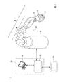
図1は、本実施形態に係るロボットシステム1の構成の一例を示す図である。ロボットシステム1は、ロボット20と、制御装置25と、教示装置50を備える。制御装置25は、ロボット制御装置30と、ロボット制御装置30と別体の情報処理装置40とによって構成される。なお、制御装置25は、これに代えて、ロボット制御装置30と情報処理装置40とが一体となって構成されてもよい。この場合、制御装置25は、以下で説明するロボット制御装置30及び情報処理装置40の機能を有する。
<Robot system configuration>
First, the configuration of the
FIG. 1 is a diagram illustrating an example of a configuration of a
ロボット20は、アームAと、アームAを支持する支持台Bを備える単腕ロボットである。単腕ロボットは、この一例におけるアームAのような1本のアーム(腕)を備えるロボットである。なお、ロボット20は、単腕ロボットに代えて、複腕ロボットであってもよい。複腕ロボットは、2本以上のアーム(例えば、2本以上のアームA)を備えるロボットである。なお、複腕ロボットのうち、2本のアームを備えるロボットは、双腕ロボットとも称される。すなわち、ロボット20は、2本のアームを備える双腕ロボットであってもよく、3本以上のアーム(例えば、3本以上のアームA)を備える複腕ロボットであってもよい。また、ロボット20は、スカラロボットや、直角座標ロボット等の他のロボットであってもよい。直角座標ロボットは、例えば、ガントリロボットである。
The
アームAは、エンドエフェクターEと、マニピュレーターMと、力検出部21を備える。
エンドエフェクターEは、この一例において、物体を把持可能な指部を備えるエンドエフェクターである。なお、エンドエフェクターEは、当該指部を備えるエンドエフェクターに代えて、空気の吸引や磁力、治具等によって物体を持ち上げることが可能なエンドエフェクターや、他のエンドエフェクターであってもよい。
The arm A includes an end effector E, a manipulator M, and a
In this example, the end effector E is an end effector including a finger portion that can grip an object. The end effector E may be an end effector capable of lifting an object by air suction, a magnetic force, a jig or the like, or another end effector, instead of the end effector including the finger portion.
エンドエフェクターEは、ケーブルによってロボット制御装置30と通信可能に接続されている。これにより、エンドエフェクターEは、ロボット制御装置30から取得される制御信号に基づく動作を行う。なお、ケーブルを介した有線通信は、例えば、イーサネット(登録商標)やUSB(Universal Serial Bus)等の規格によって行われる。また、エンドエフェクターEは、Wi−Fi(登録商標)等の通信規格により行われる無線通信によってロボット制御装置30と接続される構成であってもよい。
The end effector E is communicably connected to the
マニピュレーターMは、7つの関節を備える。また、7つの関節はそれぞれ、図示しないアクチュエーターを備える。すなわち、マニピュレーターMを備えるアームAは、7軸垂直多関節型のアームである。アームAは、支持台Bと、エンドエフェクターEと、マニピュレーターMと、マニピュレーターMが備える7つの関節それぞれのアクチュエーターとによる連携した動作によって7軸の自由度の動作を行う。なお、アームAは、6軸以下の自由度で動作する構成であってもよく、8軸以上の自由度で動作する構成であってもよい。 The manipulator M includes seven joints. Each of the seven joints includes an actuator (not shown). That is, the arm A including the manipulator M is a 7-axis vertical articulated arm. The arm A performs an operation with seven degrees of freedom by a coordinated operation by the support base B, the end effector E, the manipulator M, and the actuators of each of the seven joints included in the manipulator M. The arm A may be configured to operate with a degree of freedom of 6 axes or less, or may be configured to operate with a degree of freedom of 8 axes or more.
アームAが7軸の自由度で動作する場合、アームAは、6軸以下の自由度で動作する場合と比較して取り得る姿勢が増える。これによりアームAは、例えば、動作が滑らかになり、更にアームAの周辺に存在する物体との干渉を容易に回避することができる。また、アームAが7軸の自由度で動作する場合、アームAの制御は、アームAが8軸以上の自由度で動作する場合と比較して計算量が少なく容易である。 When the arm A operates with a degree of freedom of 7 axes, the posture that the arm A can take is increased as compared with the case where the arm A operates with a degree of freedom of 6 axes or less. Thereby, for example, the operation of the arm A is smooth, and interference with an object existing around the arm A can be easily avoided. Further, when the arm A operates with a degree of freedom of 7 axes, the control of the arm A is easy and requires a smaller calculation amount than when the arm A operates with a degree of freedom of 8 axes or more.
マニピュレーターMが備える7つの(関節に備えられた)アクチュエーターはそれぞれ、ケーブルによってロボット制御装置30と通信可能に接続されている。これにより、当該アクチュエーターは、ロボット制御装置30から取得される制御信号に基づいて、マニピュレーターMを動作させる。また、各アクチュエーターは、エンコーダーを備えている。各エンコーダーは、各エンコーダーが備えられたアクチュエーターの回転角を示す情報をロボット制御装置30に出力する。なお、ケーブルを介した有線通信は、例えば、イーサネット(登録商標)やUSB等の規格によって行われる。また、マニピュレーターMが備える7つのアクチュエーターのうちの一部又は全部は、Wi−Fi(登録商標)等の通信規格により行われる無線通信によってロボット制御装置30と接続される構成であってもよい。
Each of the seven actuators (provided at the joints) included in the manipulator M is communicably connected to the
力検出部21は、エンドエフェクターEとマニピュレーターMの間に備えられる。力検出部21は、例えば、力センサーである。力検出部21は、エンドエフェクターE、又はエンドエフェクターEにより把持された物体に作用した力を検出する。この一例では、力検出部21が検出する力が、エンドエフェクターEを並進させる力である並進力と、エンドエフェクターEを回転させるモーメントとの両方を含む概念として説明する。力検出部21は、検出した力(すなわち、並進力とモーメント)の大きさを示す値を出力値として含む力検出情報を通信によりロボット制御装置30へ出力する。
The
力検出情報は、ロボット制御装置30によるアームAの力検出情報に基づく制御である力制御に用いられる。力制御は、例えば、インピーダンス制御等のコンプライアントモーション制御のことである。なお、力検出部21は、トルクセンサー等のエンドエフェクターE、又はエンドエフェクターEにより把持された物体に加わる力(すなわち、並進力とモーメント)の大きさを示す値を検出する他のセンサーであってもよい。
The force detection information is used for force control that is control based on the force detection information of the arm A by the
力検出部21は、ケーブルによってロボット制御装置30と通信可能に接続されている。ケーブルを介した有線通信は、例えば、イーサネット(登録商標)やUSB等の規格によって行われる。なお、力検出部21とロボット制御装置30とは、Wi−Fi(登録商標)等の通信規格により行われる無線通信によって接続される構成であってもよい。
The
ロボット制御装置30は、この一例において、ロボットコントローラーである。ロボット制御装置30は、エンドエフェクターEに予め対応付けられた位置に、エンドエフェクターEとともに動くTCP(Tool Center Point)である制御点T1を設定する。エンドエフェクターEに予め対応付けられた位置は、例えば、エンドエフェクターEの重心の位置である。なお、エンドエフェクターEに対応付けられた位置は、これに代えて、他の位置であってもよい。
In this example, the
制御点T1には、制御点T1の位置を示す情報である制御点位置情報と、制御点T1の姿勢を示す情報である制御点姿勢情報とが対応付けられている。なお、制御点T1には、これらに加えて、他の情報が対応付けられる構成であってもよい。制御点位置情報及び制御点姿勢情報をロボット制御装置30が指定(決定)すると、制御点T1の位置及び姿勢が決まる。ロボット制御装置30は、制御点位置情報を指定し、指定した制御点位置情報が示す位置に制御点T1の位置が一致するようにアームAを動作させる。また、ロボット制御装置30は、当該位置制御において、制御点姿勢情報を指定する。ロボット制御装置30は、指定した制御点姿勢情報が示す姿勢に制御点T1の姿勢が一致するようにアームAを動作させる。
Control point position information that is information indicating the position of the control point T1 and control point attitude information that is information indicating the attitude of the control point T1 are associated with the control point T1. The control point T1 may be configured to be associated with other information in addition to these. When the
この一例において、制御点T1の位置は、制御点座標系TC1の原点のロボット座標系RCにおける位置によって表される。また、制御点T1の姿勢は、制御点座標系TC1の各座標軸のロボット座標系RCにおける方向によって表される。制御点座標系TC1は、制御点T1とともに動くように制御点T1に対応付けられた三次元局所座標系である。なお、この一例において、前述のエンドエフェクターEの位置及び姿勢は、制御点T1の位置及び姿勢によって表される。すなわち、エンドエフェクターEを並進させる並進力は、制御点座標系TC1の各座標軸の方向成分に分解することが可能な力のことである。また、エンドエフェクターEを回転させるモーメントは、当該各座標軸の周りに制御点T1の姿勢を回転させるモーメントのことである。 In this example, the position of the control point T1 is represented by the position of the origin of the control point coordinate system TC1 in the robot coordinate system RC. Further, the posture of the control point T1 is represented by the direction in the robot coordinate system RC of each coordinate axis of the control point coordinate system TC1. The control point coordinate system TC1 is a three-dimensional local coordinate system associated with the control point T1 so as to move with the control point T1. In this example, the position and posture of the end effector E described above are represented by the position and posture of the control point T1. That is, the translational force that translates the end effector E is a force that can be decomposed into the direction components of the coordinate axes of the control point coordinate system TC1. The moment for rotating the end effector E is a moment for rotating the posture of the control point T1 around each coordinate axis.
ロボット制御装置30は、予めユーザーから入力された制御点設定情報に基づいて制御点T1を設定する。制御点設定情報は、例えば、エンドエフェクターEの重心の位置及び姿勢と制御点T1の位置及び姿勢との相対的な位置及び姿勢を示す情報である。なお、制御点設定情報は、これに代えて、エンドエフェクターEに対応付けられた何らかの位置及び姿勢と制御点T1の位置及び姿勢との相対的な位置及び姿勢を示す情報であってもよく、マニピュレーターMに対応付けられた何らかの位置及び姿勢と制御点T1の位置及び姿勢との相対的な位置及び姿勢を示す情報であってもよく、ロボット20の他の部位に対応付けられた何らかの位置及び姿勢と制御点T1の位置及び姿勢との相対的な位置及び姿勢を示す情報であってもよい。
The
ロボット制御装置30は、教示装置50から教示点情報を取得する。そして、ロボット制御装置30は、取得した教示点情報を記憶する。教示点情報は、教示点を示す情報である。教示点は、ロボット制御装置30がアームAを動作させる際に制御点T1を経由(通過)させる複数の点である。教示点には、教示点位置情報と、教示点姿勢情報と、教示点識別情報とが対応付けられている。教示点位置情報は、教示点の位置を示す情報である。また、教示点姿勢情報は、教示点の姿勢を示す情報である。教示点識別情報は、教示点を識別する情報である。
The
この一例において、各教示点の位置は、各教示点に対応付けられた三次元局所座標系である教示点座標系の原点のロボット座標系RCにおける位置によって表される。また、教示点の姿勢は、教示点座標系の各座標軸のロボット座標系RCにおける方向によって表される。 In this example, the position of each teaching point is represented by the position in the robot coordinate system RC of the origin of the teaching point coordinate system that is a three-dimensional local coordinate system associated with each teaching point. The posture of the teaching point is represented by the direction in the robot coordinate system RC of each coordinate axis of the teaching point coordinate system.
ロボット制御装置30は、教示装置50から取得した教示点情報と、予めユーザーから入力された動作プログラムとに基づいてロボット20を動作させる。具体的には、ロボット制御装置30は、動作プログラムの各行に記載されたコマンドを上の行から順に実行する。そして、ロボット制御装置30は、これらのコマンドのうちの制御点T1を移動させるコマンドを実行する際、当該コマンドが指定する教示点識別情報が示す教示点である指定教示点を特定する。ロボット制御装置30は、特定した指定教示点に対応付けられた教示点位置情報を制御点位置情報として指定するとともに、指定教示点に対応付けられた教示点姿勢情報を制御点姿勢情報として指定する。すなわち、ロボット制御装置30は、指定教示点に基づいて制御点位置情報及び制御点姿勢情報を指定する位置制御を行う。これにより、ロボット制御装置30は、制御点T1を指定教示点に一致させることができる。なお、この一例において、ある教示点と制御点T1とが一致することは、当該教示点の位置及び姿勢と制御点T1の位置及び姿勢とが一致することを意味する。
The
また、ロボット制御装置30は、力検出部21から力検出情報を取得する。ロボット制御装置30は、前述の位置制御によって指定した制御点位置情報及び制御点姿勢情報を、当該力検出情報に基づいて補正する力制御を行う。具体的には、力制御においてロボット制御装置30は、当該力検出情報が示す力(すなわち、並進力とモーメント)の大きさが所定値となる方向へ、当該大きさが所定値となるまで制御点T1を移動させる。この際、ロボット制御装置30は、制御点T1を移動させる量である補正変化量を、当該力に基づいて算出する。補正変化量には、並進補正移動量と、回転補正角度とが含まれる。
In addition, the
並進補正移動量は、ロボット制御装置30が取得した力検出情報が示す並進力の方向に、当該並進力の大きさが第1所定値となるまで制御点T1の位置を現在の制御点T1の位置から並進させる量である。第1所定値は、この一例において、0[N]である。なお、第1所定値は、これに代えて、他の値であってもよい。ロボット制御装置30は、ロボット制御装置30に予め入力された力制御パラメーターと、動力学運動方程式と、当該力検出情報が示す並進力とに基づいて並進補正移動量を算出する。力制御パラメーターは、インピーダンスパラメーター等のコンプライアントモーション制御における弾性や粘性等を示すパラメーターのことである。
The translation correction movement amount is determined by setting the position of the control point T1 in the direction of the translation force indicated by the force detection information acquired by the
回転補正角度は、ロボット制御装置30が取得した力検出情報が示すモーメントの方向に、当該モーメントの大きさが第2所定値となるまで制御点T1の姿勢を現在の制御点T1の姿勢から回転させるオイラー角である。第2所定値は、この一例において、0[N・m]である。なお、第2所定値は、これに代えて、他の値であってもよい。ロボット制御装置30は、ロボット制御装置30に予め入力された力制御パラメーターと、動力学運動方程式と、当該力検出情報が示すモーメントとに基づいて回転補正角度を算出する。
The rotation correction angle is obtained by rotating the attitude of the control point T1 from the attitude of the current control point T1 in the direction of the moment indicated by the force detection information acquired by the
ロボット制御装置30は、位置制御によって指定した制御点位置情報が示す位置と、算出した並進補正移動量とに基づいて、当該位置から当該並進補正移動量だけ並進させた位置を補正位置として算出する。ロボット制御装置30は、算出した補正位置を示す情報を、新たな制御点位置情報として指定する。また、ロボット制御装置30は、位置制御によって指定した制御点姿勢情報が示す姿勢と、算出した回転補正角度とに基づいて、当該姿勢から当該回転補正角度だけ回転させた姿勢を補正姿勢として算出する。ロボット制御装置30は、算出した補正姿勢を示す情報を、新たな制御点姿勢情報として指定する。これにより、ロボット制御装置30は、力制御によって補正した制御点位置情報及び制御点姿勢情報が示す位置及び姿勢と、制御点T1の位置及び姿勢とを一致させることができる。
Based on the position indicated by the control point position information designated by the position control and the calculated translation correction movement amount, the
このように、ロボット制御装置30は、位置制御によって、動作プログラムに含まれるコマンドのうちの制御点T1を移動させるコマンドが教示点を指定する順に、制御点T1を教示点と一致させることにより、ロボット20に所定の作業を行わせることができる。また、ロボット制御装置30は、ロボット20が所定の作業を行っている最中に制御点T1に力(並進力とモーメント)が加わった場合、当該力を打ち消すように制御点T1を移動させることができる。
As described above, the
ロボット制御装置30は、制御点T1を移動させる際、逆運動学に基づいて、制御点位置情報及び制御点姿勢情報が示す位置及び姿勢を実現するための回転角であってマニピュレーターMが備える各アクチュエーターの回転角を算出する。ロボット制御装置30は、算出した当該回転角を示す制御信号を生成する。ロボット制御装置30は、生成した制御信号をロボット20に送信し、当該各アクチュエーターを動作させることによって制御点T1を移動させる。ここで、当該制御信号には、エンドエフェクターEを制御する制御信号も含まれる。なお、ロボット制御装置30は、ロボット20の外部に設置される構成に代えて、ロボット20に内蔵される構成であってもよい。
When the
また、ロボット制御装置30は、第1情報が対応付けられた第2情報を他の装置へ出力する。第1情報は、ロボット制御装置30が実行中の動作であってロボット20に所定の作業を行わせるための動作を示す情報である。他の装置は、この一例において、情報処理装置40である。これにより、ロボット制御装置30は、ロボット制御装置30が実行中の動作であってロボット20に所定の作業を行わせるための動作を示す第1情報が対応付けられた第2情報の記憶や表示を情報処理装置40によって行うことができる。なお、ロボット制御装置30が第2情報を出力する出力先である他の装置は、情報処理装置40に代えて、情報処理装置40と異なる何らかの装置であってもよい。
Moreover, the
第1情報は、例えば、動作プログラム内に記載されたコマンドのうちのタグコマンドによって指定される情報である。以下では、一例として、当該情報がタグIDである場合について説明する。例えば、タグコマンドが「stepID」であり、当該タグコマンドによって指定されるタグIDが「1」であった場合、動作プログラム内において当該タグコマンド及びタグIDは、「stepID=1」と記載される。なお、タグコマンドによって指定される情報は、タグIDに代えて、他の情報であってもよい。 The first information is, for example, information specified by a tag command among commands described in the operation program. Below, the case where the said information is tag ID is demonstrated as an example. For example, when the tag command is “step ID” and the tag ID specified by the tag command is “1”, the tag command and the tag ID are described as “step ID = 1” in the operation program. . The information specified by the tag command may be other information instead of the tag ID.
タグコマンドは、処理コマンドを動作プログラム内における所望のまとまり毎に区切るコマンドである。処理コマンドは、動作プログラムに含まれるコマンドのうちのタグコマンド以外のコマンドのことである。当該まとまりには、1以上の処理コマンドが含まれる。すなわち、タグコマンドは、動作プログラム内における各まとまりに含まれる処理コマンドが実行され始めるタイミングを示す情報である。このため、動作プログラムにおいて、あるまとまりに2以上の処理コマンドが含まれる場合、当該2以上の処理コマンドのうちの任意の2つの処理コマンドの間に、他のまとまりに含まれる処理コマンドが存在することはない。また、タグコマンドは、各タグコマンドが含まれるまとまりを示す情報である。 The tag command is a command that divides the processing command for each desired group in the operation program. The processing command is a command other than a tag command among commands included in the operation program. The group includes one or more processing commands. That is, the tag command is information indicating the timing at which the processing command included in each group in the operation program starts to be executed. For this reason, when two or more processing commands are included in a certain group in the operation program, there are processing commands included in another group between any two processing commands of the two or more processing commands. There is nothing. The tag command is information indicating a group including each tag command.
ロボット制御装置30は、動作プログラムにおいてタグコマンドを実行した場合、実行したタグコマンドによって指定されたタグIDを検出(特定)する。また、ロボット制御装置30は、実行したタグコマンドから次のタグコマンドまでの間に含まれる処理コマンドを1つのまとまりとして特定する。そして、ロボット制御装置30は、検出した当該タグIDを、特定した当該まとまりに含まれる各処理コマンドに対応付ける。
When the
なお、第1情報は、タグコマンドによって指定される情報(この一例において、タグID)に代えて、ロボット制御装置30が実行中の動作であってロボット20に所定の作業を行わせるための動作を示す他の情報であってもよい。また、タグIDは、まとまりを識別する数字であってもよく、まとまりを識別する文字列であってもよく、まとまりを識別する記号であってもよく、これらの組み合わせや他の情報であってもよい。
The first information is an operation that is being performed by the
第2情報は、例えば、制御量情報と、物理量情報と、コマンド情報と、成否情報を含む情報である。なお、第2情報は、これらの情報の一部又は全部に代えて、他の情報を含む構成であってもよく、これらの情報に加えて、他の情報を含む構成であってもよい。 The second information is information including control amount information, physical amount information, command information, and success / failure information, for example. The second information may be configured to include other information instead of part or all of the information, and may include other information in addition to the information.
制御量情報は、ロボット制御装置30がロボット20を制御する制御量を示す情報である。制御量情報が示す制御量は、ロボット20を動作させる際にロボット制御装置30が指定する量と、ロボット20を動作させる際にロボット制御装置30が算出する量と、ロボット制御装置30に予め入力された量と、ロボット制御装置30が計時する時刻とのそれぞれのことである。当該制御量は、この一例において、指定教示点の位置及び姿勢と、前述の補正変化量と、時刻と、前述の力制御パラメーターとのそれぞれである。当該指定教示点の位置及び姿勢は、制御量情報が生成される直前においてロボット制御装置30が位置制御によって指定した教示点の位置及び姿勢、すなわち当該直前においてロボット制御装置30が位置制御によって指定した制御点位置情報及び制御点姿勢情報が示す位置及び姿勢のことである。当該補正変化量は、当該直前においてロボット制御装置30が力制御によって算出した補正変化量のことである。当該時刻は、ロボット制御装置30が図示しない計時部によって計時した時刻であり、当該直前における時刻である。なお、制御量情報は、これらの制御量の一部又は全部に代えて、他の制御量を示す構成であってもよく、これらの制御量に加えて、他の制御量を示す構成であってもよい。
The control amount information is information indicating a control amount by which the
物理量情報は、ロボット20の動作状況を表す物理量を示す情報である。物理量情報が示す物理量は、この一例において、力と、速度と、加速度と、角速度と、角加速度とのそれぞれのことである。当該力は、物理量情報が生成される直前においてロボット制御装置30が取得した力検出情報が示す力(すなわち、並進力とモーメント)である。当該速度は、当該直前における制御点T1の速度である。当該加速度は、当該直前における制御点T1の加速度である。当該角速度は、当該直前におけるマニピュレーターMの各関節の角速度である。角加速度は、当該直前における当該各関節の角加速度である。なお、物理量情報は、これらの物理量に代えて、これらの物理量の一部又は全部に代えて、他の物理量を示す構成であってもよく、これらの物理量に加えて、他の物理量を示す構成であってもよい。
The physical quantity information is information indicating a physical quantity indicating the operation status of the
コマンド情報は、コマンド情報が生成される直前においてロボット制御装置30が実行した処理コマンドを示す情報である。成否情報は、ロボット20による所定の作業の成否を示す情報である。
The command information is information indicating a processing command executed by the
また、第2情報は、前述したように、第1情報が対応付けられた情報である。すなわち、この一例において、第2情報は、第2情報が含むコマンド情報が示すコマンドに対応付けられた第1情報(すなわち、タグID)が対応付けられた情報である。 Further, as described above, the second information is information associated with the first information. That is, in this example, the second information is information in which the first information (that is, tag ID) associated with the command indicated by the command information included in the second information is associated.
ロボット制御装置30は、物理量情報が示す物理量のそれぞれを、マニピュレーターMの各関節が備えるエンコーダーから取得した回転角を示す情報に基づいて算出する。これらの算出方法については、既知の方法を用いてもよく、これから開発される新たな方法を用いてもよいため説明を省略する。
The
また、ロボット制御装置30は、動作プログラムのすべてのコマンドを実行し終えたタイミングにおいて所定の成功条件が満たされていた場合、所定の作業が成功したと判定する。成功条件は、当該タイミングにおける第2情報の物理量情報に含まれる力(すなわち、並進力とモーメント)が所定範囲内に収まっていることである。一方、ロボット制御装置30は、動作プログラムのすべてのコマンドを実行し終えたタイミングにおいて所定の成功条件が満たされていない場合、所定の作業が失敗したと判定する。ロボット制御装置30は、このような判定の結果として前述の成否情報を生成する。なお、所定条件は、これに代えて、他の装置から何らかのエラーを示す情報を取得することや、自装置が何らかのエラーを検出すること等の他の条件であってもよい。当該エラーは、例えば、ロボット20と他の物体との干渉や、ロボット20により把持された物体の意図しない落下等のことである。
Further, the
ロボット制御装置30は、動作プログラムの実行中において、予め決められた時間が経過する毎に第2情報を生成する。当該時間は、例えば、0.5秒である。なお、当該時間は、これに代えて、他の時間であってもよい。ロボット制御装置30は、生成した第2情報を情報処理装置40に出力する。ロボット制御装置30は、例えば、TCP(Transmission Control Protocol)/IP(Internet Protocol)やUDP(User Datagram Protocol)等の形式によって第2情報を情報処理装置40に出力する。なお、ロボット制御装置30は、LAN(Local Area Network)等を介して接続された情報処理装置40に対してブロードキャストにより第2情報を出力する構成であってもよい。また、ロボット制御装置30は、情報処理装置40からの要求に応じて第2情報を生成し、生成した第2情報を情報処理装置40に出力する構成であってもよい。
The
なお、ロボット制御装置30は、動作プログラムに含まれるコマンドを実行し始めたタイミングから、すべての当該コマンドを実行し終えたタイミングまでの間、すなわち成否情報が示す成否が判定されていない間、ヌル情報を成否情報として含む第2情報を生成する。
Note that the
以下では、説明の便宜上、制御量情報及び物理量情報をまとめて出力量情報と称して説明する。また、以下では、制御量情報が示す各制御量及び物理量情報が示す各物理量をまとめて出力量と称して説明する。 Hereinafter, for convenience of explanation, the control amount information and the physical amount information will be collectively referred to as output amount information. In the following, each control amount indicated by the control amount information and each physical amount indicated by the physical amount information will be collectively referred to as an output amount.
情報処理装置40は、例えば、ノートPC(Personal Computer)である。なお、情報処理装置40は、これに代えて、ティーチングペンダント、デスクトップPC、タブレットPC、多機能携帯電話端末(スマートフォン)、携帯電話端末、PDA(Personal Digital Assistant)等の他の情報処理装置であってもよい。
The
情報処理装置40は、ロボット制御装置30が動作プログラムを実行している間において、予め決められた時間が経過する毎にロボット制御装置30から第1情報が対応付けられた第2情報を取得する。情報処理装置40は、取得した当該第2情報と当該第2情報に対応付けられた第1情報とを表示する。これにより、情報処理装置40は、第2情報と当該第2情報に対応付けられた第1情報とをユーザーに対して視覚的に提供することができる。
The
具体的には、情報処理装置40は、第1情報が対応付けられた第2情報に基づくグラフと、第1情報とを表示する。第2情報に基づくグラフは、第2情報に含まれる出力量情報が示す1以上の出力量のうちの一部又は全部それぞれの時間的な変化を表すグラフのことである。この際、情報処理装置40は、当該グラフのうち、ユーザーから受け付けた操作に基づいて選択されたグラフを表示する。これにより、情報処理装置40は、第1情報に対応付けられた第2情報の一部のうちのユーザーが所望する当該一部をユーザーに対して視覚的に提供することができる。この一例において、第2情報の一部は、第2情報に含まれる1以上の情報のうちの一部である。
Specifically, the
また、情報処理装置40は、ロボット制御装置30から取得した第2情報の履歴を示す履歴情報を記憶する。情報処理装置40は、記憶した履歴情報のうちの一部であってユーザーから受け付けた操作に基づいて履歴情報から選択された当該一部を表示する。この一例において、履歴情報のうちの一部は、情報処理装置40に記憶された1以上の履歴情報のうちの一部の履歴情報のことである。これにより、情報処理装置40は、記憶された履歴情報のうちの一部であってユーザーが所望する当該一部をユーザーに対して視覚的に提供することができる。
Further, the
教示装置50は、この一例において、ティーチングペンダントである。教示装置50は、ユーザーからの操作に基づいて、教示点情報を生成する。そして、教示装置50は、生成した教示点情報をロボット制御装置30に出力して記憶させる。
In this example, the
<ロボット制御装置及び情報処理装置のハードウェア構成>
以下、図2を参照し、ロボット制御装置30及び情報処理装置40のハードウェア構成について説明する。図2は、ロボット制御装置30及び情報処理装置40のハードウェア構成の一例を示す図である。図2は、ロボット制御装置30のハードウェア構成(図2における30番台の符号が付された機能部)と、情報処理装置40のハードウェア構成(図2における40番台の符号が付された機能部)とを便宜的に重ねて示した図である。
<Hardware configuration of robot control device and information processing device>
Hereinafter, the hardware configuration of the
ロボット制御装置30は、例えば、CPU(Central Processing Unit)31と、記憶部32と、入力受付部33と、通信部34と、表示部35を備える。また、ロボット制御装置30は、通信部34を介してロボット20、情報処理装置40、教示装置50のそれぞれと通信を行う。これらの構成要素は、バスBusを介して相互に通信可能に接続されている。
The
情報処理装置40は、例えば、CPU41と、記憶部42と、入力受付部43と、通信部44と、表示部45を備える。また、情報処理装置40は、通信部44を介してロボット制御装置30と通信を行う。これらの構成要素は、バスBusを介して相互に通信可能に接続されている。
The
CPU31は、記憶部32に格納された各種プログラムを実行する。
記憶部32は、例えば、HDD(Hard Disk Drive)やSSD(Solid State Drive)、EEPROM(Electrically Erasable Programmable Read−Only Memory)、ROM(Read−Only Memory)、RAM(Random Access Memory)等を含む。なお、記憶部32は、ロボット制御装置30に内蔵されるものに代えて、USB等のデジタル入出力ポート等によって接続された外付け型の記憶装置であってもよい。記憶部32は、ロボット制御装置30が処理する各種情報や画像、動作プログラムを含む各種のプログラム、教示点情報を格納する。
The CPU 31 executes various programs stored in the
The
入力受付部33は、例えば、表示部35と一体に構成されたタッチパネルである。なお、入力受付部33は、キーボードやマウス、タッチパッド、その他の入力装置であってもよい。
通信部34は、例えば、USB等のデジタル入出力ポートやイーサネット(登録商標)ポート等を含んで構成される。
表示部35は、例えば、液晶ディスプレイパネル、あるいは、有機EL(ElectroLuminescence)ディスプレイパネルである。
The
The
The
CPU41は、記憶部42に格納された各種プログラムを実行する。
記憶部42は、例えば、HDDやSSD、EEPROM、ROM、RAM等を含む。なお、記憶部42は、情報処理装置40に内蔵されるものに代えて、USB等のデジタル入出力ポート等によって接続された外付け型の記憶装置であってもよい。記憶部42は、情報処理装置40が処理する各種情報や画像、各種のプログラム、第2情報テーブルを格納する。第2情報テーブルは、第2情報を格納するテーブルである。
The CPU 41 executes various programs stored in the
The
入力受付部43は、例えば、表示部45と一体に構成されたタッチパネルである。なお、入力受付部43は、キーボードやマウス、タッチパッド、その他の入力装置であってもよい。
通信部44は、例えば、USB等のデジタル入出力ポートやイーサネット(登録商標)ポート等を含んで構成される。
表示部45は、例えば、液晶ディスプレイパネル、あるいは、有機ELディスプレイパネルである。
The input reception unit 43 is, for example, a touch panel configured integrally with the
The
The
<ロボット制御装置及び情報処理装置の機能構成>
以下、図3を参照し、ロボット制御装置30及び情報処理装置40の機能構成について説明する。図3は、ロボット制御装置30及び情報処理装置40の機能構成の一例を示す図である。
<Functional configuration of robot control device and information processing device>
Hereinafter, the functional configuration of the
ロボット制御装置30は、記憶部32と、入力受付部33と、通信部34と、表示部35と、制御部36を備える。
The
制御部36は、ロボット制御装置30の全体を制御する。制御部36は、表示制御部361と、力検出情報取得部363と、記憶制御部365と、ロボット制御部367を備える。制御部36が備えるこれらの機能部は、例えば、CPU31が、記憶部32に記憶された各種プログラムを実行することにより実現される。また、当該機能部のうちの一部又は全部は、LSI(Large Scale Integration)やASIC(Application Specific Integrated Circuit)等のハードウェア機能部であってもよい。
The
表示制御部361は、表示部35に表示させる各種の画面を生成する。表示制御部361は、生成した画面を表示部35に表示させる。
力検出情報取得部363は、力検出部21から力検出情報を取得する。
The
The force detection
記憶制御部365は、教示装置50から取得した教示点情報を記憶部32に記憶させる。また、記憶制御部365は、表示部35に表示された画面のうちのユーザーが動作プログラムを入力する画面によりユーザーが入力した動作プログラムを示す動作プログラム情報を記憶部32に記憶させる。
The
ロボット制御部367は、記憶部32に記憶された教示点情報及び動作プログラム情報を読み出す。ロボット制御部367は、読み出した教示点情報及び動作プログラムと力検出情報取得部363が取得した力検出情報とに基づく位置制御及び力制御によってロボット20に所定の作業を行わせる。
The
情報処理装置40は、記憶部42と、入力受付部43と、通信部44と、表示部45と、制御部46を備える。
The
制御部46は、情報処理装置40の全体を制御する。制御部46は、表示制御部461と、記憶制御部465と、動作モード切替部467を備える。制御部46が備えるこれらの機能部は、例えば、CPU41が、記憶部42に記憶された各種プログラムを実行することにより実現される。また、当該機能部のうちの一部又は全部は、LSIやASIC等のハードウェア機能部であってもよい。
The
表示制御部461は、表示部45に表示させる各種の画面を生成する。表示制御部461は、生成した画面を表示部45に表示させる。
記憶制御部465は、第2情報テーブルを記憶部42の記憶領域内に生成する。記憶制御部465は、ロボット制御装置30から取得した第2情報を、生成した第2情報テーブルに格納する。
動作モード切替部467は、ユーザーから受け付けられた操作に基づいて、情報処理装置40の動作モードを切り替える。当該動作モードの詳細については、後述する。
The
The
The operation
<ロボット制御装置が第2情報を情報処理装置に出力する処理>
以下、図4を参照し、ロボット制御装置30が第2情報を情報処理装置40に出力する処理について説明する。図4は、ロボット制御装置30が第2情報を情報処理装置40に出力する処理の流れの一例を示すフローチャートである。なお、図4に示したフローチャートでは、ロボット制御装置30がすでに教示装置50から取得した教示点情報を記憶部32に記憶済みである場合について説明する。
<Process in which the robot control device outputs the second information to the information processing device>
Hereinafter, a process in which the
ロボット制御部367は、表示制御部361が表示部35に表示させた画面において動作プログラムを実行する操作をユーザーから受け付けるまで、又は情報処理装置40から動作プログラムを実行する指示を取得する(受け付ける)まで待機する(ステップS110)。当該操作をユーザーから受け付けた、又は当該指示を情報処理装置40から取得したと判定した場合(ステップS110−YES)、ロボット制御部367は、記憶部32から教示点情報及び動作プログラム情報を読み出す(ステップS120)。次に、ロボット制御部367は、記憶部32から読み出した教示点情報に基づいて、記憶部32から読み出した動作プログラムの実行を開始する(ステップS130)。
The
次に、ロボット制御部367は、マニピュレーターMの各アクチュエーターに備えられたエンコーダーから、各アクチュエーターの回転角を示す情報を取得する。ロボット制御部367は、取得した当該回転角を示す情報に基づいて、制御点T1の速度、制御点T1の加速度、マニピュレーターMが備える各関節の角速度、当該各関節の角加速度のそれぞれを算出する。また、ロボット制御部367は、図示しない計時部から現在の時刻を検出する。また、ロボット制御部367は、現在指定している指定教示点の位置及び姿勢を特定する。また、ロボット制御部367は、特定した当該位置及び姿勢と、力検出情報取得部363が力検出部21から取得した力検出情報と、予め入力された力制御パラメーターとに基づいて補正変化量を算出する。そして、ロボット制御部367は、算出した速度、加速度、角速度、角加速度、補正変化量のそれぞれと、検出した時刻と、当該力制御パラメーターと、現在実行中のコマンドと、特定した指定教示点の位置及び姿勢と、当該コマンドに対応付けられたタグIDとに基づいて、当該タグIDを第1情報として対応付けた第2情報を生成する(ステップS140)。
Next, the
次に、ロボット制御部367は、ステップS140において生成した第2情報を情報処理装置40に出力する(ステップS150)。次に、ロボット制御部367は、動作プログラムの実行が終了したか否かを判定する(ステップS160)。動作プログラムの実行が終了したと判定した場合(ステップS160−YES)、ロボット制御部367は、処理を終了する。一方、動作プログラムの実行が終了していないと判定した場合(ステップS160−NO)、ロボット制御部367は、予め決められた時間が経過するまで待機する(ステップS170)。予め決められた時間が経過したと判定した場合(ステップS170−YES)、ロボット制御部367は、ステップS140に遷移し、再び第2情報を生成する。
Next, the
これにより、ロボット制御装置30は、ロボット制御装置30が実行したコマンドと第2情報との対応関係をタグIDによって特定することが可能な情報として、第1情報(すなわち、タグID)が対応付けられた第2情報の記憶や表示を情報処理装置40によって行うことができる。ユーザーは、情報処理装置40によって記憶や表示が行われた当該第2情報に基づいて、ロボット20が意図せず動作している原因や、ロボット20に意図した動作を行わせるために調整すべき要因等を特定することができる。その結果、ユーザーは、ロボット20による作業効率を向上させることができる。
Thereby, the
<ロボット制御装置が実行する動作プログラムの例>
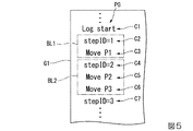
以下、図5を参照し、ロボット制御装置30が実行する動作プログラムについて説明する。図5は、ロボット制御装置30が実行する動作プログラムの一部を例示する図である。図5に示した画面G1は、表示制御部361が表示部35に表示させる画面のうちのユーザーが動作プログラムを入力する画面である。画面G1には、動作プログラムの一例である動作プログラムPGが表示されている。図5に示したコマンドC1〜コマンドC7の7つのコマンドのそれぞれは、動作プログラムPGに含まれるコマンドの一部である。ロボット制御部367は、動作プログラムPGに含まれるコマンドを上から順に1行ずつ実行することにより、動作プログラムPGを実行する。
<Example of operation program executed by robot controller>
Hereinafter, an operation program executed by the
コマンドC1は、図4に示したステップS140〜ステップS170までの処理、すなわち第2情報の生成及び出力を行う処理の実行を開始するコマンドである。
コマンドC2は、タグIDとして1を指定するタグコマンドである。
コマンドC3は、指定教示点に対応付けられた教示点識別情報としてP1を指定する処理コマンドであり、制御点T1をP1が示す指定教示点と一致させる処理コマンドである。
コマンドC4は、タグIDとして2を指定するタグコマンドである。
コマンドC5は、指定教示点に対応付けられた教示点識別情報としてP2を指定する処理コマンドであり、制御点T1をP2が示す指定教示点と一致させる処理コマンドである。
コマンドC6は、指定教示点に対応付けられた教示点識別情報としてP3を指定する処理コマンドであり、制御点T1をP3が示す指定教示点と一致させる処理コマンドである。
コマンドC7は、タグIDとして3を指定するタグコマンドである。
The command C1 is a command for starting execution of processing from step S140 to step S170 shown in FIG. 4, that is, processing for generating and outputting second information.
The command C2 is a tag command that designates 1 as a tag ID.
The command C3 is a processing command for designating P1 as teaching point identification information associated with the designated teaching point, and is a processing command for matching the control point T1 with the designated teaching point indicated by P1.
The command C4 is a tag command that designates 2 as a tag ID.
The command C5 is a processing command that designates P2 as teaching point identification information associated with the designated teaching point, and is a processing command that matches the control point T1 with the designated teaching point indicated by P2.
The command C6 is a processing command that designates P3 as teaching point identification information associated with the designated teaching point, and is a processing command that matches the control point T1 with the designated teaching point indicated by P3.
The command C7 is a tag command that designates 3 as a tag ID.
コマンドのまとまりBL1は、コマンドC2によって指定されたタグIDが対応付けられる処理コマンドのまとまりである。すなわち、コマンドC3には、タグIDとして1が対応付けられる。
コマンドのまとまりBL2は、コマンドC4によって指定されたタグIDが対応付けられる処理コマンドのまとまりである。すなわち、コマンドC5及びコマンドC6には、タグIDとして2が対応付けられる。
The command group BL1 is a group of processing commands associated with the tag ID specified by the command C2. That is, the command C3 is associated with 1 as a tag ID.
The command group BL2 is a group of processing commands associated with the tag ID specified by the command C4. That is, 2 is associated with the command C5 and the command C6 as the tag ID.
ロボット制御部367は、教示点情報に基づいて、このような動作プログラムを実行する。そして、ロボット制御部367は、第1情報が対応付けられた第2情報を生成し、生成した当該第2情報を情報処理装置40に出力する。これにより、ロボット制御装置30は、第1情報に対応付けられた第2情報の記憶や表示を情報処理装置40によって行うことができる。
The
<情報処理装置が行う処理>
以下、図6を参照し、情報処理装置40が行う処理について説明する。図6は、情報処理装置40が行う処理の流れの一例を示すフローチャートである。なお、図6に示したフローチャートでは、ステップS210の処理が開始される直前において、各種の処理を情報処理装置40に行わせる画面であるメイン画面を表示する操作を情報処理装置40がユーザーからすでに受け付けている場合について説明する。
<Processing performed by information processing device>
Hereinafter, the processing performed by the
メイン画面を表示する操作を受け付けた後、表示制御部461は、メイン画面を生成する。そして、表示制御部461は、生成したメイン画面を表示部45に表示させる(ステップS210)。次に、制御部46は、ステップS210において表示部45に表示させたメイン画面においてユーザーからの操作を受け付ける(ステップS215)。次に、制御部46の各機能部は、ステップS215において受け付けたユーザーからの操作に基づいて、当該操作に応じた処理を行う(ステップS220)。当該処理については、後述する。次に、表示制御部461は、メイン画面におけるユーザーからの操作の受け付けが終了したか否かを判定する(ステップS230)。表示制御部461は、例えば、メイン画面においてユーザーからメイン画面を削除する操作を受け付けた場合、メイン画面におけるユーザーからの操作の受け付けが終了したと判定する。表示制御部461は、メイン画面におけるユーザーからの操作の受け付けが終了したと判定した場合(ステップS230−YES)、処理を終了する。一方、メイン画面におけるユーザーからの操作の受け付けが終了していないと表示制御部461が判定した場合(ステップS230−NO)、制御部46は、ステップS215に遷移し、再びメイン画面においてユーザーからの操作を受け付ける。
After receiving the operation for displaying the main screen, the
<メイン画面において受け付けたユーザーからの操作に応じた情報処理装置の処理>
以下、図7を参照し、メイン画面において受け付けたユーザーからの操作に応じた情報処理装置40の処理について説明する。すなわち、ここでは、図7を参照し、図6に示したステップS215及びステップS220における情報処理装置40の処理について説明する。図7は、メイン画面の一例を示す図である。図7に示したメイン画面G2は、ステップS210において表示制御部461が表示部45に表示させたメイン画面の一例である。
<Processing of information processing device according to user operation accepted on main screen>
Hereinafter, with reference to FIG. 7, processing of the
メイン画面G2には、例えば、モード選択領域RA1と、表示データ選択領域RA2と、情報表示領域RA3と、ボタンBT1が含まれている。なお、メイン画面G2には、これらに加えて、他の情報やGUI(Graphical User Interface)が含まれる構成であってもよい。 The main screen G2 includes, for example, a mode selection area RA1, a display data selection area RA2, an information display area RA3, and a button BT1. The main screen G2 may include other information and GUI (Graphical User Interface) in addition to these.
モード選択領域RA1は、情報処理装置40の動作モードをユーザーが選択する領域である。
表示データ選択領域RA2は、情報表示領域RA3に表示するグラフを生成するために用いる所望の第2情報テーブルをユーザーが選択する領域である。
情報表示領域RA3は、表示データ選択領域RA2においてユーザーにより選択された第2情報テーブルに基づいて生成されたグラフであって当該第2情報テーブルに格納された第2情報に含まれる出力量情報が示す出力量の時間的な変化を表すグラフを表示する領域である。
ボタンBT1は、モード選択領域RA1においてユーザーにより選択された動作モードにおいて表示制御部461及び記憶制御部465が行う動作を実行するボタンである。
The mode selection area RA1 is an area where the user selects the operation mode of the
The display data selection area RA2 is an area where the user selects a desired second information table used for generating a graph to be displayed in the information display area RA3.
The information display area RA3 is a graph generated based on the second information table selected by the user in the display data selection area RA2, and output amount information included in the second information stored in the second information table is displayed in the information display area RA3. It is an area | region which displays the graph showing the time change of the output amount to show.
The button BT1 is a button for executing an operation performed by the
モード選択領域RA1では、ユーザーは、第1モードと、第2モードと、第3モードとの3つの動作モードの中から情報処理装置40の動作モードを選択することができる。第1モードは、グラフを情報表示領域RA3に表示するとともに、履歴を記憶部42に記憶する動作モードである。当該グラフは、対象第2情報テーブルに格納された第2情報に含まれる対象出力量の時間的な変化を表すグラフのことである。対象第2情報テーブルは、表示データ選択領域RA2においてユーザーにより選択された第2情報テーブルのことである。対象出力量は、出力量情報が示す1以上の出力量のうちの情報表示領域RA3においてユーザーにより選択された出力量のことである。当該履歴は、ロボット制御装置30から取得された第2情報の履歴のことである。第2モードは、グラフを情報表示領域RA3に表示する動作モードである。当該グラフは、対象第2情報テーブルに格納された第2情報に含まれる対象出力量の時間的な変化を表すグラフのことである。第3モードは、履歴を記憶部42に記憶する動作モードである。当該履歴は、ロボット制御装置30から取得された第2情報の履歴のことである。
In the mode selection area RA1, the user can select the operation mode of the
情報処理装置40の動作モードが第1モードである場合、ユーザーによりボタンBT1がタップされると、制御部46は、動作プログラムを実行させる指示をロボット制御装置30に出力する。また、記憶制御部465は、一時テーブルを記憶部42の記憶領域内に生成する。この際、記憶制御部465は、一時テーブルを識別する一時テーブル識別情報が対応付けられた一時テーブルを生成する。一時テーブルは、ロボット制御装置30から取得する第2情報を一時的に格納させる第2情報テーブルである。また、記憶制御部465は、履歴情報テーブルを記憶部42の記憶領域内に生成する。この際、記憶制御部465は、履歴情報テーブルを識別する履歴情報テーブル識別情報が対応付けられた履歴情報テーブルを生成する。履歴情報テーブルは、ロボット制御装置30から取得する第2情報を格納させる第2情報テーブルである。
When the operation mode of the
そして、記憶制御部465は、予め決められた時間が経過する毎に、ロボット制御装置30から第2情報を取得する。記憶制御部465は、取得した第2情報を、生成した一時情報テーブル及び生成した履歴情報テーブルの両方に格納する。この一例において、履歴情報テーブルに格納された第2情報は、第2情報の履歴を示す履歴情報のことである。また、情報処理装置40の動作モードが第1モードである場合、ユーザーによりボタンBT1がタップされると、表示制御部461は、対象第2情報テーブルに格納された第2情報に含まれる対象出力量の時間的な変化を表すグラフを生成する。表示制御部461は、生成した当該グラフを情報表示領域RA3に表示する。表示制御部461は、対象第2情報テーブルが2以上ある場合、それぞれの対象第2情報テーブル毎に、対象第2情報テーブルに格納された第2情報に含まれる対象出力量の時間的な変化を表すグラフを生成する。
Then, the
情報処理装置40の動作モードが第2モードである場合、ユーザーによりボタンBT1がタップされると、表示制御部461は、対象第2情報テーブルに格納された第2情報に含まれる対象出力量の時間的な変化を表すグラフを生成する。表示制御部461は、生成した当該グラフを情報表示領域RA3に表示する。表示制御部461は、対象第2情報テーブルが2以上ある場合、それぞれの対象第2情報テーブル毎に、対象第2情報テーブルに格納された第2情報に含まれる対象出力量の時間的な変化を表すグラフを生成する。
When the operation mode of the
情報処理装置40の動作モードが第3モードである場合、ユーザーによりボタンBT1がタップされると、制御部46は、動作プログラムを実行させる指示をロボット制御装置30に出力する。また、記憶制御部465は、一時テーブルを記憶部42の記憶領域内に生成する。この際、記憶制御部465は、一時テーブルを識別する一時テーブル識別情報が対応付けられた一時テーブルを生成する。また、記憶制御部465は、履歴情報テーブルを記憶部42の記憶領域内に生成する。この際、記憶制御部465は、履歴情報テーブルを識別する履歴情報テーブル識別情報が対応付けられた履歴情報テーブルを生成する。そして、記憶制御部465は、予め決められた時間が経過する毎に、ロボット制御装置30から第2情報を取得する。記憶制御部465は、取得した第2情報を、生成した一時情報テーブル及び生成した履歴情報テーブルの両方に格納する。
When the operation mode of the
図7に示した例では、モード選択領域RA1には、第1モードを示す情報と、当該情報に対応付けられたラジオボタンRB1と、第2モードを示す情報と、当該情報に対応付けられたラジオボタンRB2と、第3モードを示す情報と、当該情報に対応付けられたラジオボタンRB3とが含まれている。なお、モード選択領域RA1には、これらに加えて、他の情報やGUIが含まれる構成であってもよい。 In the example shown in FIG. 7, in the mode selection area RA1, information indicating the first mode, the radio button RB1 associated with the information, the information indicating the second mode, and the information associated with the information are displayed. A radio button RB2, information indicating the third mode, and a radio button RB3 associated with the information are included. The mode selection area RA1 may be configured to include other information and GUI in addition to these.
図7では、モード選択領域RA1には、「表示+記憶」という文字列が第1モードを示す情報として表示されている。また、モード選択領域RA1において、当該文字列の隣のうちの図7に向かって左側の隣には、当該文字列に対応付けられたラジオボタンRB1が表示されている。また、モード選択領域RA1には、「表示」という文字列が第2モードを示す情報として表示されている。また、モード選択領域RA1において、当該文字列の隣のうちの図7に向かって左側の隣には、当該文字列に対応付けられたラジオボタンRB2が表示されている。また、モード選択領域RA1には、「記憶」という文字列が第3モードを示す情報として表示されている。また、モード選択領域RA1において、当該文字列の隣のうちの図7に向かって左側の隣には、当該文字列に対応付けられたラジオボタンRB3が表示されている。 In FIG. 7, in the mode selection area RA1, a character string “display + storage” is displayed as information indicating the first mode. In the mode selection area RA1, a radio button RB1 associated with the character string is displayed next to the left side of FIG. In the mode selection area RA1, a character string “display” is displayed as information indicating the second mode. In the mode selection area RA1, a radio button RB2 associated with the character string is displayed next to the left side of FIG. In the mode selection area RA1, a character string “memory” is displayed as information indicating the third mode. In the mode selection area RA1, a radio button RB3 associated with the character string is displayed on the left side of FIG.
ユーザーは、モード選択領域RA1に表示された3つのラジオボタン(ラジオボタンRB1〜ラジオボタンRB3)のうちのいずれか1つをタップ(クリック)することによって、情報処理装置40の動作モードを選択することができる。
The user selects an operation mode of the
例えば、ユーザーがラジオボタンRB1をタップした場合、表示制御部461は、ラジオボタンRB1が選択されたことを示す情報をラジオボタンRB1上に重ねて表示する。そして、動作モード切替部467は、情報処理装置40の現在の動作モードを第1モードに切り替える。図7には、ユーザーによりラジオボタンRB1が選択された状態のモード選択領域RA1が示されている。当該モード選択領域RA1では、ラジオボタンRB1上に、ラジオボタンRB1が選択されたことを示す情報として黒丸が重ねて表示されている。なお、当該情報は、黒丸に代えて、チェックマークやラジオボタンの色の変更等の他の情報であってもよい。
For example, when the user taps the radio button RB1, the
また、例えば、ユーザーがラジオボタンRB2をタップした場合、表示制御部461は、ラジオボタンRB2が選択されたことを示す情報をラジオボタンRB2上に重ねて表示する。そして、動作モード切替部467は、情報処理装置40の現在の動作モードを第2モードに切り替える。
Further, for example, when the user taps the radio button RB2, the
また、例えば、ユーザーが「記憶」という文字列に対応付けられたラジオボタンRB3をタップした場合、表示制御部461は、ラジオボタンRB3が選択されたことを示す情報をラジオボタンRB3上に重ねて表示する。そして、動作モード切替部467は、情報処理装置40の現在の動作モードを第3モードに切り替える。
Further, for example, when the user taps the radio button RB3 associated with the character string “memory”, the
表示データ選択領域RA2では、ユーザーは、一時テーブル及び履歴情報テーブルとして記憶部42に記憶されている1以上の第2情報テーブルの中からユーザーが所望の1以上の第2情報テーブルを選択することができる。
In the display data selection area RA2, the user selects one or more desired second information tables from one or more second information tables stored in the
図7に示した例では、表示データ選択領域RA2には、受信データを表す情報RR0と、当該情報に対応付けられたチェックボックスCB1と、第1欄RR1と、第1欄RR1に対応付けられたチェックボックスCB2と、第1欄RR1に対応付けられたボタンBT2と、第2欄RR2と、第2欄RR2に対応付けられたチェックボックスCB3と、第2欄RR2に対応付けられたボタンBT3とが表示されている。 In the example shown in FIG. 7, the display data selection area RA2 is associated with information RR0 representing received data, a check box CB1 associated with the information, a first column RR1, and a first column RR1. Check box CB2, button BT2 associated with the first column RR1, second column RR2, check box CB3 associated with the second column RR2, and button BT3 associated with the second column RR2. And are displayed.
受信データは、一時テーブルとして記憶部42に記憶された第2情報テーブルのことである。すなわち、受信データを表す情報RR0は、当該一時テーブルを表している。第1欄RR1は、ユーザーによりボタンBT2がタップされた場合に表示されるファイル選択画面においてユーザーにより選択されたファイル名が表示される欄のことである。当該ファイル名は、この一例において、記憶部42に記憶された1以上の履歴情報テーブルのそれぞれを識別する履歴情報テーブル識別情報のことである。すなわち、当該ファイル名は、り、当該ファイル名が識別する履歴情報テーブルを表している。第2欄RR2は、ユーザーによりボタンBT3がタップされた場合に表示されるファイル選択画面においてユーザーにより選択されたファイル名が表示される欄のことである。当該ファイル名は、この一例において、記憶部42に記憶された1以上の履歴情報テーブルのそれぞれを識別する履歴情報テーブル識別情報のことである。すなわち、当該ファイル名は、当該ファイル名が識別する履歴情報テーブルを表している。
The received data is a second information table stored in the
ここで、図8を参照し、ファイル選択画面について説明する。図8は、メイン画面G2上に重ねて表示されたファイル選択画面の一例を示す図である。図8に示したファイル選択画面G3は、ユーザーによりボタンBT2又はボタンBT3がタップされた場合に表示されるファイル選択画面の一例である。ファイル選択画面G3には、ファイル一覧表示領域LT1と、ボタンBT4が含まれている。なお、ファイル選択画面G3には、これらに加えて、他の情報やGUIが含まれる構成であってもよい。 Here, the file selection screen will be described with reference to FIG. FIG. 8 is a diagram showing an example of a file selection screen displayed so as to overlap the main screen G2. The file selection screen G3 illustrated in FIG. 8 is an example of a file selection screen that is displayed when the button BT2 or the button BT3 is tapped by the user. The file selection screen G3 includes a file list display area LT1 and a button BT4. The file selection screen G3 may include other information and GUI in addition to these.
ファイル一覧表示領域LT1は、記憶部42に記憶された1以上の履歴情報テーブルを識別するファイル名が表示される領域である。図8に示した例では、ファイル一覧表示領域LT1には、1つ目の履歴情報テーブルを表すファイル名である「file0001」と、2つ目の履歴情報テーブルを表すファイル名である「file0002」と、3つ目の履歴情報テーブルを表すファイル名である「file0003」と、4つ目の履歴情報テーブルを表すファイル名である「file0004」等が表示されている。
The file list display area LT1 is an area in which a file name for identifying one or more history information tables stored in the
ユーザーによりボタンBT2がタップされたことによって表示されたファイル選択画面G3において、ファイル一覧表示領域LT1に表示された1以上のファイル名のうちの1つをユーザーがタップした場合、表示制御部461は、ユーザーがタップしたファイル名を図7に示した第1欄RR1に表示させる。そして、表示制御部461は、当該ファイル選択画面G3をメイン画面G2上から削除する。また、当該ファイル選択画面G3においてボタンBT4がタップされた場合、表示制御部461は、当該ファイル選択画面G3をメイン画面G2上から削除する。すなわち、ボタンBT4は、ファイル選択画面G3におけるユーザーによるファイル名の選択をキャンセルするボタンである。
When the user taps one of one or more file names displayed in the file list display area LT1 on the file selection screen G3 displayed by tapping the button BT2 by the user, the
また、ユーザーによりボタンBT3がタップされたことによって表示されたファイル選択画面G3において、ファイル一覧表示領域LT1に表示された1以上のファイル名のうちの1つをユーザーがタップした場合、表示制御部461は、ユーザーがタップしたファイル名を図7に示した第2欄RR2に表示させる。そして、表示制御部461は、当該ファイル選択画面G3をメイン画面G2上から削除する。また、当該ファイル選択画面G3においてボタンBT4がタップされた場合、表示制御部461は、当該ファイル選択画面G3をメイン画面G2上から削除する。
When the user taps one of one or more file names displayed in the file list display area LT1 on the file selection screen G3 displayed when the user taps the button BT3, the display control
図7に戻る。図7に示した表示データ選択領域RA2には、「受信データ」という文字列が受信データを表す情報RR0として表示されている。また、表示データ選択領域RA2において、当該文字列の隣のうちの図7に向かって左側の隣には、当該文字列に対応付けられたチェックボックスCB1が表示されている。 Returning to FIG. In the display data selection area RA2 shown in FIG. 7, a character string “received data” is displayed as information RR0 representing the received data. In the display data selection area RA2, a check box CB1 associated with the character string is displayed next to the left side of FIG. 7 next to the character string.
また、図7に示した表示データ選択領域RA2において第1欄RR1には、ファイル選択画面G3においてユーザーにより選択されたファイル名として「ファイル1データ(ファイル名)」という文字列が表示されている。また、表示データ選択領域RA2において、当該文字列の隣のうちの図7に向かって左側の隣には、当該文字列に対応付けられたチェックボックスCB2が表示されている。また、表示データ選択領域RA2において、図7に向かって当該文字列の右側には、当該文字列に対応付けられたボタンBT2が表示されている。
In the display data selection area RA2 shown in FIG. 7, the first column RR1 displays a character string “
また、図7に示した表示データ選択領域RA2において第2欄RR2には、ファイル選択画面G3においてユーザーにより選択されたファイル名として「ファイル2データ(ファイル名)」という文字列が表示されている。また、表示データ選択領域RA2において、当該文字列の隣のうちの図7に向かって左側の隣には、当該文字列に対応付けられたチェックボックスCB2が表示されている。また、表示データ選択領域RA2において、図7に向かって当該文字列の右側には、当該文字列に対応付けられたボタンBT3が表示されている。
In the display data selection area RA2 shown in FIG. 7, a character string “
ユーザーは、表示データ選択領域RA2に表示された3つのチェックボックス(チェックボックスCB1〜チェックボックスCB3)の中から1以上の所望のチェックボックスをタップ(クリック)することによって、受信データを表す情報RR0が表す一時テーブルと、第1欄RR1に表示されたファイル名が表す履歴情報テーブルと、第2欄RR2に表示されたファイル名が表す履歴情報テーブルとのうちの一部又は全部を、1以上の対象第2情報テーブルとして選択することができる。 The user taps (clicks) one or more desired check boxes from among the three check boxes (check boxes CB1 to CB3) displayed in the display data selection area RA2, thereby displaying information RR0 representing received data. One or more of the temporary table represented by, the history information table represented by the file name displayed in the first column RR1, and the history information table represented by the file name displayed in the second column RR2 As the target second information table.
例えば、ユーザーがチェックボックスCB1をタップした場合、表示制御部461は、受信データを表す情報RR0が表す一時テーブルを、1以上の対象第2情報テーブルの1つとして特定する。また、ユーザーがチェックボックスCB2をタップした場合、表示制御部461は、第1欄RR1に表示されたファイル名が表す履歴情報テーブルを、1以上の対象第2情報テーブルの1つとして特定する。また、ユーザーがチェックボックスCB3をタップした場合、表示制御部461は、第2欄RR2に表示されたファイル名が表す履歴情報テーブルを、1以上の対象第2情報テーブルの1つとして特定する。
For example, when the user taps the check box CB1, the
また、例えば、ユーザーがチェックボックスCB1及びチェックボックスCB2をタップした場合、表示制御部461は、受信データを表す情報RR0が表す一時テーブルと、第1欄RR1に表示されたファイル名が表す履歴情報テーブルとのそれぞれを、1以上の対象第2情報テーブルの1つとして特定する。また、ユーザーがチェックボックスCB2及びチェックボックスCB3をタップした場合、第1欄RR1に表示されたファイル名が表す履歴情報テーブルと、第2欄RR2に表示されたファイル名が表す履歴情報テーブルとのそれぞれを、1以上の対象第2情報テーブルの1つとして特定する。また、ユーザーがチェックボックスCB1及びチェックボックスCB3をタップした場合、表示制御部461は、受信データを表す情報RR0が表す一時情報テーブルと、第2欄RR2に表示されたファイル名が表す履歴情報テーブルとのそれぞれを、1以上の対象第2情報テーブルの1つとして特定する。
Further, for example, when the user taps the check box CB1 and the check box CB2, the
また、例えば、ユーザーがチェックボックスCB1〜チェックボックスCB3のそれぞれをタップした場合、表示制御部461は、受信データを表す情報RR0が表す一時テーブルと、第1欄RR1に表示されたファイル名が表す履歴情報テーブルと、第2欄RR2に表示されたファイル名が表す履歴情報テーブルとのそれぞれを、1以上の対象第2情報テーブルの1つとして特定する。
For example, when the user taps each of the check boxes CB1 to CB3, the
また、表示制御部461は、チェックボックスCB1〜チェックボックスCB3のうちのいずれかがタップされた場合、タップされたチェックボックスが選択されたことを示す情報を当該チェックボックス上に重ねて表示する。図7に示した例では、当該情報は、当該チェックボックス上に重ねて表示されているチェックマークである。すなわち、図7に示した例は、ユーザーによりチェックボックスCB1が選択されている例である。なお、当該情報は、チェックマークに代えて、黒丸やチェックマークの色の変更等の他の情報であってもよい。
In addition, when any one of the check boxes CB1 to CB3 is tapped, the
以下では、一例として、図7に示した通り、ユーザーによりチェックボックスCB1のみがタップされた場合について説明する。なお、前述した通り、チェックボックスCB1〜チェックボックスCB3の中から2以上のチェックボックスがユーザーによりタップされた場合、表示制御部461は、2以上の対象第2情報テーブル毎に、対象第2情報テーブルに格納された第2情報に含まれる対象出力量の時間的な変化を表すグラフを生成する。
Hereinafter, as an example, a case where only the check box CB1 is tapped by the user will be described as shown in FIG. As described above, when two or more check boxes are tapped by the user from the check boxes CB1 to CB3, the
情報表示領域RA3では、ユーザーは、対象第2情報テーブルに含まれる対象出力量の時間的な変化を表すグラフを表示することができる。この一例では、対象第2情報テーブルが、受信データを表す情報RR0が表す一時テーブルである。このため、表示制御部461は、当該一時テーブルに格納された第2情報に含まれる対象出力量の時間的な変化を表すグラフを表示する。
In the information display area RA3, the user can display a graph representing a temporal change in the target output amount included in the target second information table. In this example, the target second information table is a temporary table represented by information RR0 representing received data. For this reason, the
図7に示した例では、情報表示領域RA3には、ボタンBT5と、グラフ表示領域GRF1が含まれている。なお、情報表示領域RA3には、これらに加えて、他の情報やGUIが含まれる構成であってもよい。 In the example shown in FIG. 7, the information display area RA3 includes a button BT5 and a graph display area GRF1. In addition to these, the information display area RA3 may be configured to include other information and GUI.
ボタンBT5は、出力量選択画面を表示させるボタンである。ユーザーによりボタンBT5がタップされた場合、表示制御部461は、出力量選択画面をメイン画面G2に重ねて表示する。出力量選択画面は、ユーザーが所望の出力量を対象出力量として選択する画面である。ここで、図9を参照し、出力量選択画面について説明する。図9は、メイン画面G2に重ねて表示された出力量選択画面の一例を示す図である。
The button BT5 is a button for displaying an output amount selection screen. When the button BT5 is tapped by the user, the
図9に示した出力量選択画面G4は、ユーザーによりボタンBT5がタップされた場合に表示される出力量選択画面の一例である。出力量選択画面G4には、出力量一覧表示領域LT2と、ボタンBT6が含まれている。なお、出力量選択画面G4には、これらに加えて、他の情報やGUIが含まれる構成であってもよい。 The output amount selection screen G4 illustrated in FIG. 9 is an example of an output amount selection screen that is displayed when the button BT5 is tapped by the user. The output amount selection screen G4 includes an output amount list display area LT2 and a button BT6. The output amount selection screen G4 may be configured to include other information and GUI in addition to these.
出力量一覧表示領域LT2は、出力量情報が示す各出力量を表す情報の一覧が表示される領域である。以下では、一例として、各出力量を表す情報が、各出力量の名称である場合について説明する。なお、当該情報は、これに代えて、出力量を表す図形等の他の情報であってもよい。図9に示した例では、出力量一覧表示領域LT2には、出力量情報が示す出力量のうちの力の名称である「力」と、当該出力量のうちの速度の名称である「速度」と、当該出力量のうちの指定教示点の位置の名称である「位置」と、当該出力量のうちの指定教示点の姿勢の名称である「姿勢」等が表示されている。 The output amount list display area LT2 is an area in which a list of information representing each output amount indicated by the output amount information is displayed. Below, the case where the information showing each output amount is a name of each output amount is demonstrated as an example. The information may be other information such as a graphic representing the output amount instead. In the example illustrated in FIG. 9, the output amount list display area LT <b> 2 includes “force” that is the name of the force in the output amount indicated by the output amount information and “speed” that is the name of the speed in the output amount. ”,“ Position ”which is the name of the position of the designated teaching point in the output amount,“ posture ”which is the name of the posture of the designated teaching point in the output amount, and the like.
出力量一覧表示領域LT2に表示された1以上の名称のうちの1つをユーザーがタップした場合、表示制御部461は、ユーザーがタップした名称が表す出力量を、対象出力量の1つとして特定する。また、ユーザーにより複数の名称が所定期間以内にタップされた場合、表示制御部461は、タップされた当該複数の名称の組み合わせを、対象出力量の1つとして特定する。所定期間は、例えば、2秒である。なお、所定期間は、これに代えて、他の時間であってもよい。
When the user taps one of the one or more names displayed in the output amount list display area LT2, the
ボタンBT6は、出力量選択画面G4をメイン画面G2上から削除するボタンである。ユーザーによりボタンBT6がタップされた場合、表示制御部461は、出力量選択画面G4をメイン画面G2上から削除する。
The button BT6 is a button for deleting the output amount selection screen G4 from the main screen G2. When the button BT6 is tapped by the user, the
図7に戻る。出力量選択画面G4においてユーザーにより1以上の対象出力量(2以上の出力量の組み合わせを含む)が選択された場合、表示制御部461は、選択された1以上の対象出力量毎に、対象出力量に対応付けられたタブを情報表示領域RA3に表示する。以下では、一例として、出力量選択画面G4においてユーザーにより選択された1以上の対象出力量が、出力量情報が示す出力量のうちの力、位置、力及び位置(上記の2以上の出力量の組み合わせの例)の3つである場合について説明する。
Returning to FIG. When one or more target output amounts (including combinations of two or more output amounts) are selected by the user on the output amount selection screen G4, the
図7に示した例では、情報表示領域RA3には、タブTB1と、タブTB2と、タブTB3が表示されている。タブTB1は、この一例における1以上の対象出力量のうち力に対応付けられたタブである。タブTB2は、この一例における1以上の対象出力量のうち位置に対応付けられたタブである。タブTB3は、この一例における1以上の対象出力量のうち力及び位置に対応付けられたタブである。 In the example shown in FIG. 7, a tab TB1, a tab TB2, and a tab TB3 are displayed in the information display area RA3. The tab TB1 is a tab associated with a force among one or more target output amounts in this example. The tab TB2 is a tab associated with a position among one or more target output amounts in this example. The tab TB3 is a tab associated with a force and a position among one or more target output amounts in this example.
ユーザーは、ボタンBT1をタップした後、これらのタブのうちのいずれか1つをタップすることにより、タップしたタブに対応付けられた対象出力量の時間的な変化を表すグラフをグラフ表示領域GRF1に表示することができる。 After the user taps the button BT1, the user taps one of these tabs to display a graph representing the temporal change in the target output amount associated with the tapped tab in the graph display area GRF1. Can be displayed.
例えば、ユーザーによりボタンBT1がタップされた後、情報表示領域RA3に表示されたタブのうちのタブTB1がユーザーによりタップされた場合、表示制御部461は、対象第2情報テーブルに格納された第2情報に含まれる対象出力量のうちのタブTB1に対応付けられた対象出力量である力の時間的な変化を表すグラフを生成する。この一例において、表示制御部461は、一時テーブルに格納された第2情報に含まれる対象出力量のうちのタブTB1に対応付けられた対象出力量である力の時間的な変化を表すグラフを生成する。表示制御部461は、生成した当該グラフをグラフ表示領域GRF1に表示する。
For example, after the button BT1 is tapped by the user and the tab TB1 among the tabs displayed in the information display area RA3 is tapped by the user, the
また、例えば、ユーザーによりボタンBT1がタップされた後、情報表示領域RA3に表示されたタブのうちのタブTB2がユーザーによりタップされた場合、表示制御部461は、対象第2情報テーブルに格納された第2情報に含まれる対象出力量のうちのタブTB2に対応付けられた対象出力量である位置(指定教示点の位置)の時間的な変化を表すグラフを生成する。この一例において、表示制御部461は、一時テーブルに格納された第2情報に含まれる対象出力量のうちのタブTB2に対応付けられた対象出力量である位置の時間的な変化を表すグラフを生成する。表示制御部461は、生成した当該グラフをグラフ表示領域GRF1に表示する。
For example, when the user taps the tab TB2 among the tabs displayed in the information display area RA3 after the user taps the button BT1, the
また、例えば、ユーザーによりボタンBT1がタップされた後、情報表示領域RA3に表示されたタブのうちのタブTB3がユーザーによりタップされた場合、表示制御部461は、対象第2情報テーブルに格納された第2情報に含まれる対象出力量のうちのタブTB3に対応付けられた対象出力量である力及び位置(指定教示点の位置)それぞれの時間的な変化を表すグラフを生成する。この一例において、表示制御部461は、一時テーブルに格納された第2情報に含まれる対象出力量のうちのタブTB3に対応付けられた対象出力量である力及び位置の時間的な変化を表すグラフを生成する。表示制御部461は、生成した2つの当該グラフを重ねて(又は並べて)グラフ表示領域GRF1に表示する。
In addition, for example, when the user taps the button TB1 and the tab TB3 among the tabs displayed in the information display area RA3, the
図7に示した例では、情報表示領域RA3に表示されたタブのうちのユーザーによりタップされたタブは、タブTB1である。このため、グラフ表示領域GRF1には、この一例における対象第2情報テーブルである一時テーブルに格納された第2情報に含まれる対象出力量のうちのタブTB1に対応付けられた対象出力量である力の時間的な変化を表すグラフが表示されている。図7に示した曲線LN1は、当該力の時間的な変化を表している。また、当該グラフの縦軸は、対象出力量である力を示す。また、当該グラフの横軸は、時間を示す。 In the example shown in FIG. 7, the tab tapped by the user among the tabs displayed in the information display area RA3 is the tab TB1. For this reason, the graph display region GRF1 is the target output amount associated with the tab TB1 among the target output amounts included in the second information stored in the temporary table that is the target second information table in this example. A graph showing the change in force over time is displayed. A curve LN1 shown in FIG. 7 represents a temporal change in the force. In addition, the vertical axis of the graph indicates the force that is the target output amount. The horizontal axis of the graph indicates time.
このように、情報処理装置40は、対象第2情報テーブルに格納された第2情報に含まれる対象出力量の時間的な変化を表すグラフを表示することができる。これにより、ユーザーは、例えば、対象出力量が制御量であった場合、ロボット制御装置30に予め設定する力制御パラメーターを変更する毎に、変更した力制御パラメーターによってロボット制御装置30がロボット20を制御する制御量の時間的な変化を視覚的に確認することができる。その結果、ユーザーは、当該グラフ(すなわち、第2情報)に基づいて、ロボット20に所定の作業を効率的に行わせるために適した力制御パラメーターを選択できる。すなわち、情報処理装置40は、当該グラフ(すなわち、第2情報)に基づいて、ロボット20に所定の作業を効率的に行わせるために適した力制御パラメーターをユーザーに選択させることができる。
As described above, the
また、グラフ表示領域GRF1に表示されたグラフには、当該グラフを生成する際に用いた対象第2情報テーブルに格納された1以上の第2情報のそれぞれに対応付けられた第1情報が表示される。表示制御部461は、グラフ表示領域GRF1にグラフを表示する際、当該グラフを生成する際に用いた対象第2情報テーブルに基づいて、対象第2情報テーブルに格納された第2情報のそれぞれに対応付けられた第1情報が変化していない期間を1つの区間として特定し、特定した1以上の区間を示す情報を当該グラフに表示させる。
In addition, the graph displayed in the graph display area GRF1 displays the first information associated with each of the one or more second information stored in the target second information table used when generating the graph. Is done. When the
図7に示した例では、グラフ表示領域GRF1に表示されたグラフには、表示制御部461が特定した1以上の区間を示す情報として、情報LV1〜情報LV3のそれぞれが表示されている。
In the example shown in FIG. 7, each of information LV <b> 1 to information LV <b> 3 is displayed as information indicating one or more sections specified by the
情報LV1は、グラフ表示領域GRF1に表示されたグラフにおいて、この一例における第1情報であるタグIDとして1が第2情報に対応付けられている区間を示す情報である。情報LV1は、当該区間を矢印によって表している。また、情報LV1は、当該区間において第2情報に対応付けられた第1情報を、当該矢印の下に配置した当該第1情報であるタグID(すなわち、1)によって表している。 The information LV1 is information indicating a section in which 1 is associated with the second information as the tag ID which is the first information in this example in the graph displayed in the graph display area GRF1. The information LV1 represents the section by an arrow. In addition, the information LV1 represents the first information associated with the second information in the section by the tag ID (that is, 1) that is the first information arranged under the arrow.
また、情報LV2は、グラフ表示領域GRF1に表示されたグラフにおいて、この一例における第1情報であるタグIDとして2が第2情報に対応付けられている区間を示す情報である。情報LV2は、当該区間を矢印によって表している。また、情報LV2は、当該区間において第2情報に対応付けられた第1情報を、当該矢印の下に配置した当該第1情報であるタグID(すなわち、2)によって表している。 The information LV2 is information indicating a section in which 2 is associated with the second information as the tag ID which is the first information in this example in the graph displayed in the graph display area GRF1. The information LV2 represents the section by an arrow. Further, the information LV2 represents the first information associated with the second information in the section by the tag ID (that is, 2) that is the first information arranged under the arrow.
また、図7に示した例では、グラフ表示領域GRF1に表示されたグラフの横軸は、時間(h、m、s)を示していた。しかし、当該横軸が時間とは異なる他の量を示す場合、当該グラフの横軸では、タグIDが第2情報に対応付けられている区間を示す情報LV1〜情報LV3それぞれの区間を表す矢印は、互いに色や形状が異なる構成であってもよい。また、この場合、当該区間は、矢印によって表される構成に代えて、他の記号や図形、文字等によって表される構成であってもよい。 In the example shown in FIG. 7, the horizontal axis of the graph displayed in the graph display area GRF1 indicates time (h, m, s). However, when the horizontal axis indicates another amount different from time, on the horizontal axis of the graph, an arrow indicating each section of information LV1 to information LV3 indicating a section in which the tag ID is associated with the second information. These may have different colors and shapes. In this case, the section may be represented by another symbol, figure, character, or the like instead of the structure represented by the arrow.
また、情報LV3は、グラフ表示領域GRF1に表示されたグラフにおいて、この一例における第1情報であるタグIDとして3が第2情報に対応付けられている区間を示す情報である。情報LV3は、当該区間を矢印によって表している。また、情報LV3は、当該区間において第2情報に対応付けられた第1情報を、当該矢印の下に配置した当該第1情報であるタグID(すなわち、3)によって表している。 The information LV3 is information indicating a section in which 3 is associated with the second information as the tag ID which is the first information in this example in the graph displayed in the graph display area GRF1. The information LV3 represents the section by an arrow. In addition, the information LV3 represents the first information associated with the second information in the section by the tag ID (that is, 3) that is the first information arranged under the arrow.
図7に示した点線BR1及び点線BR2は、グラフ表示領域GRF1に表示されたグラフにおいて、第2情報に対応付けられた第1情報が変化したタイミングを示す情報である。表示制御部461は、グラフ表示領域GRF1にグラフを表示する際、当該タイミングを示す情報を当該グラフに表示する。
The dotted line BR1 and the dotted line BR2 illustrated in FIG. 7 are information indicating the timing at which the first information associated with the second information is changed in the graph displayed in the graph display area GRF1. When the graph is displayed in the graph display area GRF1, the
このように、情報処理装置40は、ロボット制御装置30から取得した第2情報が格納された第2情報テーブルに基づいて、当該第2情報と当該第2情報に対応付けられた第1情報とをグラフ表示領域GRF1に表示させる。これにより、ユーザーは、ロボット20が意図していない動作を行っている区間にロボット制御装置30により実行されていたコマンドを容易に特定することができる。また、ユーザーは、ロボット20に所定の作業をより効率的に行わせるために力制御パラメーターを調整すべき区間においてロボット制御装置30により実行されている処理コマンドを容易に特定することができる。その結果、ユーザーは、ロボット20に作業を効率的に行わせるために適した力制御のパラメーターを第1情報及び第2情報に基づいて選択することができる。すなわち、情報処理装置40は、ロボット20に作業を効率的に行わせるために適した力制御のパラメーターを第1情報及び第2情報に基づいてユーザーに選択させることができる。
As described above, the
また、グラフ表示領域GRF1に表示されたグラフには、当該グラフを生成する際に用いた対象出力量が有する1以上の自由度を示す情報と、当該情報に対応付けられたチェックボックスとが表示される。表示制御部461は、グラフ表示領域GRF1にグラフを表示する際、当該グラフを生成する際に用いた対象出力量が有する1以上の自由度を示す情報と、当該情報に対応付けられたチェックボックスとをグラフ表示領域GRF1に表示する。また、表示制御部461は、グラフ表示領域GRF1に表示するグラフを生成する際、当該グラフを生成する際に用いる対象第2情報テーブルに格納された第2情報に基づいて対象出力量が有する自由度毎に、当該自由度の時間的な変化を示すグラフを生成する。ユーザーがグラフ表示領域GRF1に表示された当該自由度を示す情報のうちの1つをタップした場合、表示制御部461は、タップされた当該情報が示す自由度の時間的な変化を示すグラフをグラフ表示領域GRF1に表示する。
Further, the graph displayed in the graph display area GRF1 displays information indicating one or more degrees of freedom of the target output amount used when generating the graph and a check box associated with the information. Is done. When the
図7に示した例では、グラフ表示領域GRF1に表示されたグラフには、対象出力量である力が有する自由度を示す情報、すなわち並進力が有する3つの自由度を示す情報である「Fx」、「Fy」、「Fz」と、モーメントが有する3つの自由度を示す情報である「Tx」、「Ty」、「Tz」とが表示されている。「Fx」は、並進力が有する3つの自由度のうちの制御点座標系TC1におけるX軸方向の自由度を示す情報である。「Fy」は、並進力が有する3つの自由度のうちの制御点座標系TC1におけるY軸方向の自由度を示す情報である。「Fz」は、並進力が有する3つの自由度のうちの制御点座標系TC1におけるZ軸方向の自由度を示す情報である。「Tx」は、モーメントが有する3つの自由度のうちの制御点座標系TC1におけるX軸周りの回転の自由度を示す情報である。「Ty」は、モーメントが有する3つの自由度のうちの制御点座標系TC1におけるY軸周りの回転の自由度を示す情報である。「Tz」は、モーメントが有する3つの自由度のうちの制御点座標系TC1におけるZ軸周りの回転の自由度を示す情報である。また、グラフ表示領域GRF1に表示されたグラフには、これらの自由度のそれぞれに対応付けられたチェックボックスとして、チェックボックスET1〜チェックボックスET6が表示されている。 In the example illustrated in FIG. 7, the graph displayed in the graph display region GRF <b> 1 includes information indicating the degrees of freedom that the force that is the target output amount has, that is, information indicating the three degrees of freedom that the translational force has. , “Fy”, “Fz” and “Tx”, “Ty”, “Tz”, which are information indicating the three degrees of freedom of the moment, are displayed. “Fx” is information indicating the degree of freedom in the X-axis direction in the control point coordinate system TC1 among the three degrees of freedom of the translational force. “Fy” is information indicating the degree of freedom in the Y-axis direction in the control point coordinate system TC1 among the three degrees of freedom of the translational force. “Fz” is information indicating the degree of freedom in the Z-axis direction in the control point coordinate system TC1 among the three degrees of freedom of the translational force. “Tx” is information indicating the degree of freedom of rotation around the X axis in the control point coordinate system TC1 among the three degrees of freedom of the moment. “Ty” is information indicating the degree of freedom of rotation about the Y axis in the control point coordinate system TC1 among the three degrees of freedom of the moment. “Tz” is information indicating the degree of freedom of rotation around the Z axis in the control point coordinate system TC1 among the three degrees of freedom of the moment. In the graph displayed in the graph display area GRF1, check boxes ET1 to ET6 are displayed as check boxes associated with each of these degrees of freedom.
チェックボックスET1は、「Fx」が示す自由度に対応付けられたチェックボックスである。チェックボックスET2は、「Fy」が示す自由度に対応付けられたチェックボックスである。チェックボックスET3は、「Fz」が示す自由度に対応付けられたチェックボックスである。チェックボックスET4は、「Tx」が示す自由度に対応付けられたチェックボックスである。チェックボックスET5は、「Ty」が示す自由度に対応付けられたチェックボックスである。チェックボックスET6は、「Tz」が示す自由度に対応付けられたチェックボックスである。 The check box ET1 is a check box associated with the degree of freedom indicated by “Fx”. The check box ET2 is a check box associated with the degree of freedom indicated by “Fy”. The check box ET3 is a check box associated with the degree of freedom indicated by “Fz”. The check box ET4 is a check box associated with the degree of freedom indicated by “Tx”. The check box ET5 is a check box associated with the degree of freedom indicated by “Ty”. The check box ET6 is a check box associated with the degree of freedom indicated by “Tz”.
図7に示した例では、これらチェックボックスのうちのチェックボックスET1がユーザーによりタップされた状態が示されている。チェックボックスET1がユーザーによりタップされた場合、表示制御部461は、チェックボックスET1に対応付けられた情報である「Fx」が示す自由度であって、対象出力量が有する自由度の時間的な変化を表すグラフをグラフ表示領域GRF1に表示する。
In the example illustrated in FIG. 7, a state in which the check box ET1 among these check boxes is tapped by the user is illustrated. When the check box ET1 is tapped by the user, the
また、チェックボックスET1〜チェックボックスET6のうちの2以上のチェックボックスがユーザーによりタップされた場合、表示制御部461は、タップされたチェックボックスのそれぞれに対応付けられた情報が示す自由度であって、対象出力量が有する自由度の時間的な変化を表すグラフをグラフ表示領域GRF1に表示する。例えば、チェックボックスET1とチェックボックスET2とがユーザーによりタップされた場合、表示制御部461は、2つのグラフをグラフ表示領域GRF1に表示する。当該2つのグラフは、チェックボックスET1に対応付けられた情報である「Fx」が示す自由度であって対象出力量が有する自由度の時間的な変化を表すグラフと、チェックボックスET2に対応付けられた情報である「Fy」が示す自由度であって、対象出力量が有する自由度の時間的な変化を表すグラフとの2つのグラフである。この場合におけるグラフ表示領域GRF1の表示例を図10に示した。図10は、2つのグラフが同時に表示されたグラフ表示領域GRF1を含むメイン画面G2の一例を示す図である。
In addition, when two or more check boxes among the check boxes ET1 to ET6 are tapped by the user, the
このように、情報処理装置40は、グラフ表示領域GRF1に表示されたチェックボックスをユーザーによりタップされることにより、対象出力量が有する自由度のうちのユーザーが所望する1以上の自由度の時間的な変化を表すグラフを表示することができる。これにより、情報処理装置40は、自由度毎の出力量の時間的な変化をユーザーに視覚的に提供することができる。その結果、情報処理装置40は、ロボット20に所定の作業を効率的に行わせるために適した力制御パラメーターをユーザーに容易に選択させることができる。
As described above, the
<グラフ表示領域に表示されるグラフの他の例>
図7〜図10に示したグラフ表示領域GRF1には、波形グラフが表示されていたが、表示制御部461は、波形グラフに代えて、他の種類のグラフを表示してもよい。以下、図11を参照し、グラフ表示領域GRF1に表示されるグラフの他の例について説明する。図11は、グラフ表示領域GRF1に表示されるグラフの他の例を示す図である。
<Other examples of graphs displayed in the graph display area>
Although the waveform graph is displayed in the graph display region GRF1 illustrated in FIGS. 7 to 10, the
図11に示したグラフPLTは、図を簡略化するために2次元グラフとして示している。なお、表示制御部461は、グラフ表示領域GRF1においてN次元グラフを表示してもよい。Nは、1以上の整数である。グラフPLTの縦軸は、ロボット座標系RCにおけるY軸方向の位置を示す。グラフPLTの横軸は、ロボット座標系RCにおけるX軸方向の位置を示す。グラフPLTは、ロボット20に所定の作業を複数回行わせた場合において、複数回の所定の作業のそれぞれ毎に、動作プログラムのすべてのコマンドを実行し終えたタイミングにおける制御点T1の位置に対して、当該タイミングにおいて判定された所定の作業の成否を示す情報をプロットした散布図である。当該位置は、制御点T1のロボット座標系RCにおける位置である。
The graph PLT shown in FIG. 11 is shown as a two-dimensional graph in order to simplify the drawing. Note that the
表示制御部461は、ユーザーから受け付けた操作に基づいて、ユーザーが所望する期間に記憶された複数の履歴情報テーブルを記憶部42からすべて読み出す。表示制御部461は、読み出した複数の履歴情報テーブルのそれぞれに格納された第2情報に基づいて、グラフPLTを生成する。具体的には、表示制御部461は、読み出した複数の履歴情報テーブルのそれぞれに格納された第2情報に含まれる出力量情報が示す位置及び補正変化量に基づいて、動作プログラムのすべてのコマンドを実行し終えたタイミングにおける制御点T1の位置を算出する。そして、表示制御部461は、算出した位置と、当該位置を算出するために用いた第2情報に含まれる成否情報が示す成否とに基づいて、グラフPLTを生成する。
The
図7に示したグラフPLTでは、「×」がプロットされた位置のX座標及びY座標が、ロボット20が所定の作業を失敗した場合において最終的に到達した制御点T1のロボット座標系RCにおける位置を示している。一方、グラフPLTでは、「〇」がプロットされた位置のX座標及びY座標が、ロボット20が所定の作業を成功した場合において最終的に到達した制御点T1のロボット座標系RCにおける位置を示している。図7に示した例では、グラフPLTからは、「×」と「〇」はそれぞれ、ロボット座標系RCにおいて互いに異なる領域に集まる傾向が見て取れる。このことから、ユーザーは、ロボット制御装置30に設定する力制御パラメーターを、制御点T1が最終的に到達するロボット座標系RCにおける位置を「〇」が集まる領域内の位置となるように調整することにより、ロボット20が所定の作業を成功させる可能性を高くすることができる。すなわち、ユーザーは、グラフPLTを見ることにより、ロボット20が所定の作業において最終的に到達する制御点T1のロボット座標系RCにおける位置を、所定の作業の成否の指標として力制御パラメーターを調整することができる。
In the graph PLT shown in FIG. 7, the X coordinate and the Y coordinate at the position where “x” is plotted are the robot coordinate systems RC of the control point T1 that is finally reached when the
このように、情報処理装置40は、波形グラフに代えて、散布図をグラフ表示領域GRF1に表示することができる。この場合、情報処理装置40は、記憶部42に記憶された複数の履歴情報テーブルに基づいて散布図を生成する。これにより、情報処理装置40は、複数の履歴情報テーブルに基づいて生成された散布図により、波形グラフでは表せない情報をユーザーに提供することができる。なお、情報処理装置40は、波形グラフ及び散布図に代えて、他の種類のグラフをグラフ表示領域GRF1に表示する構成であってもよい。
In this way, the
また、情報処理装置40は、ロボット20が所定の処理を行った回数と、記憶部42に記憶された当該所定の処理毎に生成された履歴情報テーブルとに基づいて、ユーザーが所望する出力量の平均や分散、ピーク値等のような統計量を算出する構成であってもよい。この場合、情報処理装置40は、算出した統計量を第2情報テーブルと異なる他のテーブルに格納する構成であってもよい。そして、当該場合、情報処理装置40は、算出した統計量に応じたグラフをグラフ表示領域GRF1に表示する。
Further, the
なお、情報処理装置40は、上記において説明したグラフ表示領域GRF1において、プロットされる点や記号の色、明るさ、大きさ、形状等を、ユーザーにより受け付けられた操作に基づいて表示したグラフに応じて変化させる構成であってもよく、変化させない構成であってもよい。例えば、情報処理装置40は、図11に示した6つの「×」及び6つの「〇」のそれぞれを、互いに異なる色によりグラフ表示領域GRF1に表示する構成であってもよい。また、情報処理装置40は、上記において説明したグラフ表示領域GRF1において、描かれる曲線や直線の色、明るさ、大きさ、形状等を、ユーザーにより受け付けられた操作に基づいて表示したグラフに応じて変化させる構成であってもよく、変化させない構成であってもよい。例えば、情報処理装置40は、図10においてグラフ表示領域GRF1に表示された2本の曲線のそれぞれを、互いに異なる色によりグラフ表示領域GRF1に表示する構成であってもよい。
In the graph display area GRF1 described above, the
<情報処理装置が第2情報を履歴情報テーブルに格納する処理>
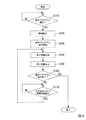
以下、図12を参照し、情報処理装置40が第2情報を一時テーブル及び履歴情報テーブルの両方に格納する処理について説明する。図12は、情報処理装置40が第2情報を一時テーブル及び履歴情報テーブルの両方に格納する処理の流れの一例を示すフローチャートである。なお、図12において、記憶制御部465は、すでに一時テーブル及び履歴情報テーブルを記憶部42の記憶領域に生成済みである場合について説明する。
<Processing in which information processing apparatus stores second information in history information table>
Hereinafter, a process in which the
記憶制御部365は、ロボット制御装置30から第2情報を取得するまで待機する(ステップS310)。ロボット制御装置30から第2情報を取得したと判定した場合(ステップS310−YES)、記憶制御部465は、取得した第2情報を、記憶部42に記憶された一時テーブル及び履歴情報テーブルの両方に格納する(ステップS320)。次に、記憶制御部465は、ステップS310において取得した第2情報に含まれる成否情報がNull情報ではあるか否かを判定する(ステップS330)。当該第2情報に含まれる成否情報がNull情報であったと判定した場合(ステップS330−YES)、記憶制御部465は、ステップS310に遷移し、再びロボット制御装置30から第2情報を取得するまで待機する。一方、ステップS310において取得した第2情報に含まれる成否情報がNull情報ではなかったと判定した場合(ステップS330−NO)、記憶制御部465は、処理を終了する。
The
このように、情報処理装置40は、ロボット制御装置30から取得した第2情報を、記憶部42に記憶された一時テーブル及び履歴情報テーブルの両方に格納する。これにより、情報処理装置40は、記憶部42に記憶された履歴情報テーブルに格納された1以上の第2情報のうちの一部であってユーザーが所望する当該一部をユーザーに対して視覚的に提供することができる。
As described above, the
なお、上記において説明した第2情報には、例えば、撮像部に関する情報である撮像部関連情報や、ビジュアルサーボによるロボット20の制御に関する情報であるビジュアルサーボ関連情報等が含まれる構成であってもよい。撮像部関連情報には、例えば、撮像部が設置されたロボット座標系における位置を示す情報や、撮像部の画素数を示す情報等が含まれる。ビジュアルサーボ関連情報には、例えば、ビジュアルサーボに用いられるリファレンスモデルを示す情報等が含まれる。
Note that the second information described above may include, for example, imaging unit related information that is information related to the imaging unit, visual servo related information that is information related to control of the
<第2情報テーブルのデータ構造>
以下、第2情報テーブルのデータ構造について説明する。上記において説明した第2情報テーブルのデータ構造には、如何なるデータ構造を採用してもよい。
<Data structure of second information table>
Hereinafter, the data structure of the second information table will be described. Any data structure may be adopted as the data structure of the second information table described above.
例えば、第2情報テーブルのデータ構造は、以下のように実データ部と、ヘッダ部と、フッタ部によって構成されてもよい。 For example, the data structure of the second information table may include an actual data part, a header part, and a footer part as follows.
実データ部は、上記において説明した第2情報テーブルに格納された各情報を格納する。
ヘッダ部は、実データ部への当該各情報の格納の開始時刻、当該各情報の名称や単位、当該各情報を示すためにユーザーが指定する任意の文字列、当該各情報の格納間隔、当該各情報の格納予定時間、当該各情報の格納の開始条件、当該各情報の格納の終了条件、当該各情報を出力したセンサー等の機器を示す情報等を格納する。
フッタ部は、当該各情報の格納の終了理由等を格納する。当該終了理由には、例えば、予定した時間の経過、当該終了条件の達成、意図しない動作の発生等が含まれる。
The actual data part stores each information stored in the second information table described above.
The header part includes the start time of storing each piece of information in the actual data part, the name and unit of each piece of information, an arbitrary character string designated by the user to indicate the piece of information, the storage interval of the piece of information, The storage time of each information, the storage start condition of each information, the storage end condition of each information, information indicating a device such as a sensor that outputs the information, and the like are stored.
The footer unit stores a reason for ending storage of each piece of information. The termination reason includes, for example, the elapse of a scheduled time, achievement of the termination condition, occurrence of an unintended operation, and the like.
なお、これらの実データ部、ヘッダ部、フッタ部には、必要に応じて他の情報が含まれる構成であってもよい。 The actual data part, the header part, and the footer part may include other information as necessary.
以上のように、ロボット制御装置30は、ロボット制御装置30が実行中の動作であってロボット20に作業を行わせるための動作を示す第1情報(この一例において、タグID)が対応付けられた第2情報を他の装置(この一例において、情報処理装置40)へ出力する。これにより、ロボット制御装置30が実行中の動作であってロボット20に作業を行わせるための動作を示す第1情報が対応付けられた第2情報の記憶や表示を他の装置によって行うことができる。
As described above, the
また、ロボット制御装置30は、第1情報が対応付けられた第2情報であってロボット20を制御する制御量を示す情報を含む第2情報を他の装置へ出力する。これにより、ロボット制御装置30は、第1情報が対応付けられた第2情報であってロボット20を制御する制御量を示す情報を含む第2情報の記憶や表示を他の装置によって行うことができる。
Further, the
また、ロボット制御装置30は、第1情報が対応付けられた第2情報であってロボット20の動作状況を表す物理量を示す情報を含む第2情報を他の装置へ出力する。これにより、ロボット制御装置30は、第1情報が対応付けられた第2情報であってロボット20の動作状況を表す物理量を示す情報を含む第2情報の記憶や表示を他の装置によって行うことができる。
In addition, the
また、情報処理装置40は、ロボット制御装置30から第1情報に対応付けられた第2情報を取得し、取得した当該第2情報と当該第2情報が対応付けられた第1情報とを表示部に表示させる。これにより、情報処理装置40は、第2情報と当該第2情報に対応付けられた第1情報とをユーザーに対して視覚的に提供することができる。
Further, the
また、情報処理装置40は、第2情報の一部であってユーザーから受け付けた操作に基づいて第2情報から選択された当該一部を表示部(この一例において、表示部45)に表示させる。これにより、情報処理装置40は、第2情報の一部のうちのユーザーが所望する当該一部をユーザーに対して視覚的に提供することができる。
Further, the
また、情報処理装置40は、ロボット制御装置30から取得した第2情報の履歴を示す履歴情報を記憶部(この一例において、記憶部42)に記憶し、履歴情報のうちの一部であってユーザーから受け付けた操作に基づいて履歴情報から選択された当該一部を表示部に表示させる。これにより、情報処理装置40は、記憶された履歴情報のうちの一部であってユーザーが所望する当該一部をユーザーに対して視覚的に提供することができる。
The
また、情報処理装置40は、ユーザーから受け付けた操作に基づいて、複数の第1情報の中から、ロボットの制御点の位置及び姿勢を力制御によって変化させる量である補正変化量を示す情報を含む第2情報に対応付けられた第1情報を選択し、選択した当該第1情報に対応付けられた第2情報の少なくとも一部を表示部に表示する。これにより、情報処理装置40は、ロボットの制御点の位置及び姿勢を力制御によって変化させる量である補正変化量を示す情報を含む第2情報の少なくとも一部であってユーザーが所望する当該一部をユーザーに対して視覚的に提供することができる。
In addition, the
以上、この発明の実施形態を、図面を参照して詳述してきたが、具体的な構成はこの実施形態に限られるものではなく、この発明の要旨を逸脱しない限り、変更、置換、削除等されてもよい。 The embodiment of the present invention has been described in detail with reference to the drawings. However, the specific configuration is not limited to this embodiment, and changes, substitutions, deletions, and the like are possible without departing from the gist of the present invention. May be.
また、以上に説明した装置(例えば、ロボット制御装置30や情報処理装置40)における任意の構成部の機能を実現するためのプログラムを、コンピューター読み取り可能な記録媒体に記録し、そのプログラムをコンピューターシステムに読み込ませて実行するようにしてもよい。なお、ここでいう「コンピューターシステム」とは、OS(Operating System)や周辺機器等のハードウェアを含むものとする。また、「コンピューター読み取り可能な記録媒体」とは、フレキシブルディスク、光磁気ディスク、ROM、CD(Compact Disk)−ROM等の可搬媒体、コンピューターシステムに内蔵されるハードディスク等の記憶装置のことをいう。さらに「コンピューター読み取り可能な記録媒体」とは、インターネット等のネットワークや電話回線等の通信回線を介してプログラムが送信された場合のサーバーやクライアントとなるコンピューターシステム内部の揮発性メモリー(RAM)のように、一定時間プログラムを保持しているものも含むものとする。
In addition, a program for realizing the functions of arbitrary components in the devices described above (for example, the
また、上記のプログラムは、このプログラムを記憶装置等に格納したコンピューターシステムから、伝送媒体を介して、あるいは、伝送媒体中の伝送波により他のコンピューターシステムに伝送されてもよい。ここで、プログラムを伝送する「伝送媒体」は、インターネット等のネットワーク(通信網)や電話回線等の通信回線(通信線)のように情報を伝送する機能を有する媒体のことをいう。
また、上記のプログラムは、前述した機能の一部を実現するためのものであってもよい。さらに、上記のプログラムは、前述した機能をコンピューターシステムにすでに記録されているプログラムとの組み合わせで実現できるもの、いわゆる差分ファイル(差分プログラム)であってもよい。
In addition, the above program may be transmitted from a computer system storing the program in a storage device or the like to another computer system via a transmission medium or by a transmission wave in the transmission medium. Here, the “transmission medium” for transmitting the program refers to a medium having a function of transmitting information, such as a network (communication network) such as the Internet or a communication line (communication line) such as a telephone line.
Further, the above program may be for realizing a part of the functions described above. Further, the program may be a so-called difference file (difference program) that can realize the above-described functions in combination with a program already recorded in the computer system.
1…ロボットシステム、20…ロボット、21…力検出部、30…ロボット制御装置、31、41…CPU、32、42…記憶部、33、43…入力受付部、34、44…通信部、35、45…表示部、36、46…制御部、40…情報処理装置、50…教示装置、361、461…表示制御部、363…力検出情報取得部、365、465…記憶制御部、367…ロボット制御部、467…動作モード切替部
DESCRIPTION OF
Claims (8)
前記ロボット制御装置が実行中の動作であって前記ロボットに作業を行わせるための動作を示す第1情報が対応付けられた第2情報を他の装置へ出力する、
ロボット制御装置。 A robot control device for operating a robot,
Outputting the second information associated with the first information indicating the operation being executed by the robot control device and causing the robot to perform an operation to another device;
Robot control device.
請求項1に記載のロボット制御装置。 The second information includes information indicating a control amount for controlling the robot.
The robot control apparatus according to claim 1.
請求項1又は2に記載のロボット制御装置。 The second information includes information indicating a physical quantity representing an operation state of the robot.
The robot control apparatus according to claim 1 or 2.
情報処理装置。 The second information is acquired from the robot control device according to any one of claims 1 to 3, and the acquired second information and the first information associated with the second information are displayed. To display
Information processing device.
請求項4に記載の情報処理装置。 Displaying a part of the second information selected from the second information based on an operation received from a user on the display unit;
The information processing apparatus according to claim 4.
請求項4又は5に記載の情報処理装置。 A history information indicating a history of the second information acquired from the robot control device according to any one of claims 1 to 3 is stored in a storage unit, and a part of the history information is received from a user. Displaying the part selected from the history information based on the received operation on the display unit;
The information processing apparatus according to claim 4 or 5.
ユーザーから受け付けた操作に基づいて、複数の前記第1情報の中から当該情報を含む前記第2情報に対応付けられた前記第1情報を選択し、選択した当該第1情報に対応付けられた第2情報の少なくとも一部を前記表示部に表示する、
請求項4から6のうちいずれか一項に記載の情報処理装置。 The second information includes information indicating a correction change amount, which is an amount by which the position and posture of the control point of the robot is changed by force control,
Based on the operation received from the user, the first information associated with the second information including the information is selected from a plurality of the first information, and is associated with the selected first information. Displaying at least part of the second information on the display unit;
The information processing apparatus according to any one of claims 4 to 6.
請求項4から7のうちいずれか一項に記載の情報処理装置と、
前記ロボット制御装置に制御されるロボットと、
を備えるロボットシステム。 The robot control device according to any one of claims 1 to 3,
An information processing apparatus according to any one of claims 4 to 7,
A robot controlled by the robot control device;
A robot system comprising:
Priority Applications (3)
| Application Number | Priority Date | Filing Date | Title |
|---|---|---|---|
| JP2016047951A JP2017159429A (en) | 2016-03-11 | 2016-03-11 | Robot control device, information processing device, and robot system |
| US15/455,460 US20170259433A1 (en) | 2016-03-11 | 2017-03-10 | Robot control device, information processing device, and robot system |
| CN201710145932.9A CN107179743A (en) | 2016-03-11 | 2017-03-13 | Robot controller, information processor and robot system |
Applications Claiming Priority (1)
| Application Number | Priority Date | Filing Date | Title |
|---|---|---|---|
| JP2016047951A JP2017159429A (en) | 2016-03-11 | 2016-03-11 | Robot control device, information processing device, and robot system |
Publications (2)
| Publication Number | Publication Date |
|---|---|
| JP2017159429A true JP2017159429A (en) | 2017-09-14 |
| JP2017159429A5 JP2017159429A5 (en) | 2019-04-04 |
Family
ID=59852941
Family Applications (1)
| Application Number | Title | Priority Date | Filing Date |
|---|---|---|---|
| JP2016047951A Withdrawn JP2017159429A (en) | 2016-03-11 | 2016-03-11 | Robot control device, information processing device, and robot system |
Country Status (1)
| Country | Link |
|---|---|
| JP (1) | JP2017159429A (en) |
Cited By (2)
| Publication number | Priority date | Publication date | Assignee | Title |
|---|---|---|---|---|
| JP2020023024A (en) * | 2018-08-08 | 2020-02-13 | オムロン株式会社 | Control system, analyzer, and control method |
| JP2021000672A (en) * | 2019-06-19 | 2021-01-07 | ファナック株式会社 | Adjustment support device |
Citations (11)
| Publication number | Priority date | Publication date | Assignee | Title |
|---|---|---|---|---|
| JPH0715990A (en) * | 1993-06-29 | 1995-01-17 | Mitsubishi Electric Corp | Controller of industrial robot |
| JPH08174458A (en) * | 1994-12-27 | 1996-07-09 | Nissan Motor Co Ltd | Force controller for assembling robot |
| JPH0916228A (en) * | 1995-06-26 | 1997-01-17 | Fanuc Ltd | Moment error correcting method of force control robot, and force control robot |
| JPH10260710A (en) * | 1997-03-17 | 1998-09-29 | Fujitsu Ltd | Controller for robot |
| JP2006026640A (en) * | 2004-07-12 | 2006-02-02 | Matsushita Electric Ind Co Ltd | Arc welding robot |
| US20070244599A1 (en) * | 2006-04-14 | 2007-10-18 | Fanuc Robotics America, Inc. | A Method for Optimizing a Robot Program and a Robot System |
| JP2012206200A (en) * | 2011-03-29 | 2012-10-25 | Daihen Corp | Robot system, and portable teaching operation apparatus |
| JP2013000856A (en) * | 2011-06-20 | 2013-01-07 | Seiko Epson Corp | Robot control system and robot system |
| US20130226346A1 (en) * | 2012-02-27 | 2013-08-29 | Scott Dreslinski | Robotic process logger |
| JP2014117720A (en) * | 2012-12-14 | 2014-06-30 | Daihen Corp | Arc welding robot system |
| JP2014233814A (en) * | 2013-06-04 | 2014-12-15 | 株式会社安川電機 | Robot teaching auxiliary device, robot system and robot teaching method |
-
2016
- 2016-03-11 JP JP2016047951A patent/JP2017159429A/en not_active Withdrawn
Patent Citations (12)
| Publication number | Priority date | Publication date | Assignee | Title |
|---|---|---|---|---|
| JPH0715990A (en) * | 1993-06-29 | 1995-01-17 | Mitsubishi Electric Corp | Controller of industrial robot |
| JPH08174458A (en) * | 1994-12-27 | 1996-07-09 | Nissan Motor Co Ltd | Force controller for assembling robot |
| JPH0916228A (en) * | 1995-06-26 | 1997-01-17 | Fanuc Ltd | Moment error correcting method of force control robot, and force control robot |
| JPH10260710A (en) * | 1997-03-17 | 1998-09-29 | Fujitsu Ltd | Controller for robot |
| JP2006026640A (en) * | 2004-07-12 | 2006-02-02 | Matsushita Electric Ind Co Ltd | Arc welding robot |
| US20070244599A1 (en) * | 2006-04-14 | 2007-10-18 | Fanuc Robotics America, Inc. | A Method for Optimizing a Robot Program and a Robot System |
| JP2012206200A (en) * | 2011-03-29 | 2012-10-25 | Daihen Corp | Robot system, and portable teaching operation apparatus |
| JP2013000856A (en) * | 2011-06-20 | 2013-01-07 | Seiko Epson Corp | Robot control system and robot system |
| US20130226346A1 (en) * | 2012-02-27 | 2013-08-29 | Scott Dreslinski | Robotic process logger |
| JP2013208702A (en) * | 2012-02-27 | 2013-10-10 | Fanuc Robotics America Corp | Robotic process logger |
| JP2014117720A (en) * | 2012-12-14 | 2014-06-30 | Daihen Corp | Arc welding robot system |
| JP2014233814A (en) * | 2013-06-04 | 2014-12-15 | 株式会社安川電機 | Robot teaching auxiliary device, robot system and robot teaching method |
Cited By (4)
| Publication number | Priority date | Publication date | Assignee | Title |
|---|---|---|---|---|
| JP2020023024A (en) * | 2018-08-08 | 2020-02-13 | オムロン株式会社 | Control system, analyzer, and control method |
| CN110815208A (en) * | 2018-08-08 | 2020-02-21 | 欧姆龙株式会社 | Control system, analysis device, and control method |
| JP2021000672A (en) * | 2019-06-19 | 2021-01-07 | ファナック株式会社 | Adjustment support device |
| JP7239399B2 (en) | 2019-06-19 | 2023-03-14 | ファナック株式会社 | Adjustment support device |
Similar Documents
| Publication | Publication Date | Title |
|---|---|---|
| JP6361213B2 (en) | Robot control apparatus, robot, robot system, teaching method, and program | |
| US10828782B2 (en) | Robot system, robot, and robot control apparatus | |
| CN107414842B (en) | Control device, robot, and robot system | |
| JP6816364B2 (en) | Controls, robots, and robot systems | |
| US20170259433A1 (en) | Robot control device, information processing device, and robot system | |
| EP2963513B1 (en) | Teaching apparatus and robot system | |
| US20180029232A1 (en) | Control apparatus and robot | |
| WO2009113339A1 (en) | Operation teaching system and operation teaching method | |
| JP2017019068A (en) | Teaching device, robot, and robot system | |
| JP6326765B2 (en) | Teaching apparatus, robot, robot system, method, and program | |
| US20180085920A1 (en) | Robot control device, robot, and robot system | |
| JP2018144228A (en) | Robot control apparatus, robot, robot system, teaching method, and program | |
| JP2017159429A (en) | Robot control device, information processing device, and robot system | |
| JP6488571B2 (en) | Teaching apparatus and robot system | |
| JP6455869B2 (en) | Robot, robot system, control device, and control method | |
| JP6958091B2 (en) | Robot system and robot control method | |
| CN115869069A (en) | Surgical robot control method, device, equipment, medium and system | |
| JP2017047478A (en) | Control device, robot, and robot system | |
| JP2016013590A (en) | Teaching device, and robot system | |
| JP2019111588A (en) | Robot system, information processor, and program | |
| US20120314020A1 (en) | Move-it: monitoring, operating, visualizing, editing integration toolkit for reconfigurable physical computing | |
| Deák et al. | Smartphone–controlled industrial robots: Design and user performance evaluation | |
| JP7070245B2 (en) | Information processing device, motion control program, and motion control method | |
| JP2016063309A (en) | Image processor and robot system | |
| CN116546437A (en) | Pose determination method and device, electronic equipment and readable storage medium |
Legal Events
| Date | Code | Title | Description |
|---|---|---|---|
| RD05 | Notification of revocation of power of attorney |
Free format text: JAPANESE INTERMEDIATE CODE: A7425 Effective date: 20180907 |
|
| RD03 | Notification of appointment of power of attorney |
Free format text: JAPANESE INTERMEDIATE CODE: A7423 Effective date: 20181120 |
|
| A521 | Request for written amendment filed |
Free format text: JAPANESE INTERMEDIATE CODE: A523 Effective date: 20190225 |
|
| A621 | Written request for application examination |
Free format text: JAPANESE INTERMEDIATE CODE: A621 Effective date: 20190225 |
|
| A131 | Notification of reasons for refusal |
Free format text: JAPANESE INTERMEDIATE CODE: A131 Effective date: 20200128 |
|
| A977 | Report on retrieval |
Free format text: JAPANESE INTERMEDIATE CODE: A971007 Effective date: 20200129 |
|
| A761 | Written withdrawal of application |
Free format text: JAPANESE INTERMEDIATE CODE: A761 Effective date: 20200330 |