JP2017159053A - Orthotic or prosthetic joint device and method for controlling joint device - Google Patents
Orthotic or prosthetic joint device and method for controlling joint device Download PDFInfo
- Publication number
- JP2017159053A JP2017159053A JP2017077565A JP2017077565A JP2017159053A JP 2017159053 A JP2017159053 A JP 2017159053A JP 2017077565 A JP2017077565 A JP 2017077565A JP 2017077565 A JP2017077565 A JP 2017077565A JP 2017159053 A JP2017159053 A JP 2017159053A
- Authority
- JP
- Japan
- Prior art keywords
- bending
- torque
- extension
- joint device
- pressure
- Prior art date
- Legal status (The legal status is an assumption and is not a legal conclusion. Google has not performed a legal analysis and makes no representation as to the accuracy of the status listed.)
- Granted
Links
- 238000000034 method Methods 0.000 title claims abstract description 38
- 239000012530 fluid Substances 0.000 claims abstract description 48
- 238000005452 bending Methods 0.000 claims description 127
- 210000000629 knee joint Anatomy 0.000 claims description 30
- 210000002414 leg Anatomy 0.000 claims description 12
- 230000007423 decrease Effects 0.000 claims description 11
- 230000009194 climbing Effects 0.000 claims description 6
- 230000009467 reduction Effects 0.000 claims description 6
- 230000003247 decreasing effect Effects 0.000 claims description 5
- 230000009471 action Effects 0.000 claims description 4
- 238000004891 communication Methods 0.000 claims description 2
- 238000007599 discharging Methods 0.000 claims description 2
- 210000003127 knee Anatomy 0.000 description 41
- 238000010586 diagram Methods 0.000 description 20
- 230000033001 locomotion Effects 0.000 description 15
- 210000002683 foot Anatomy 0.000 description 10
- 210000001699 lower leg Anatomy 0.000 description 10
- 210000003423 ankle Anatomy 0.000 description 8
- 230000004048 modification Effects 0.000 description 8
- 238000012986 modification Methods 0.000 description 8
- 238000006243 chemical reaction Methods 0.000 description 5
- 238000003825 pressing Methods 0.000 description 5
- 230000005021 gait Effects 0.000 description 4
- 238000010248 power generation Methods 0.000 description 4
- 238000005265 energy consumption Methods 0.000 description 3
- 239000007788 liquid Substances 0.000 description 3
- 230000008569 process Effects 0.000 description 3
- 210000000544 articulatio talocruralis Anatomy 0.000 description 2
- 230000005540 biological transmission Effects 0.000 description 2
- 239000003990 capacitor Substances 0.000 description 2
- 230000008859 change Effects 0.000 description 2
- 230000006837 decompression Effects 0.000 description 2
- 238000004146 energy storage Methods 0.000 description 2
- 210000003414 extremity Anatomy 0.000 description 2
- 210000004744 fore-foot Anatomy 0.000 description 2
- 238000012856 packing Methods 0.000 description 2
- 210000001364 upper extremity Anatomy 0.000 description 2
- 210000000689 upper leg Anatomy 0.000 description 2
- 230000001174 ascending effect Effects 0.000 description 1
- 230000008901 benefit Effects 0.000 description 1
- 238000010276 construction Methods 0.000 description 1
- 230000001419 dependent effect Effects 0.000 description 1
- 230000036541 health Effects 0.000 description 1
- 210000001503 joint Anatomy 0.000 description 1
- 210000003141 lower extremity Anatomy 0.000 description 1
- 238000012423 maintenance Methods 0.000 description 1
- 238000012544 monitoring process Methods 0.000 description 1
- 210000002346 musculoskeletal system Anatomy 0.000 description 1
- 230000000737 periodic effect Effects 0.000 description 1
- 230000003252 repetitive effect Effects 0.000 description 1
- 230000001502 supplementing effect Effects 0.000 description 1
- 230000003319 supportive effect Effects 0.000 description 1
- 230000002747 voluntary effect Effects 0.000 description 1
Images


Classifications
-
- A—HUMAN NECESSITIES
- A61—MEDICAL OR VETERINARY SCIENCE; HYGIENE
- A61F—FILTERS IMPLANTABLE INTO BLOOD VESSELS; PROSTHESES; DEVICES PROVIDING PATENCY TO, OR PREVENTING COLLAPSING OF, TUBULAR STRUCTURES OF THE BODY, e.g. STENTS; ORTHOPAEDIC, NURSING OR CONTRACEPTIVE DEVICES; FOMENTATION; TREATMENT OR PROTECTION OF EYES OR EARS; BANDAGES, DRESSINGS OR ABSORBENT PADS; FIRST-AID KITS
- A61F2/00—Filters implantable into blood vessels; Prostheses, i.e. artificial substitutes or replacements for parts of the body; Appliances for connecting them with the body; Devices providing patency to, or preventing collapsing of, tubular structures of the body, e.g. stents
- A61F2/50—Prostheses not implantable in the body
- A61F2/68—Operating or control means
- A61F2/70—Operating or control means electrical
-
- A—HUMAN NECESSITIES
- A61—MEDICAL OR VETERINARY SCIENCE; HYGIENE
- A61F—FILTERS IMPLANTABLE INTO BLOOD VESSELS; PROSTHESES; DEVICES PROVIDING PATENCY TO, OR PREVENTING COLLAPSING OF, TUBULAR STRUCTURES OF THE BODY, e.g. STENTS; ORTHOPAEDIC, NURSING OR CONTRACEPTIVE DEVICES; FOMENTATION; TREATMENT OR PROTECTION OF EYES OR EARS; BANDAGES, DRESSINGS OR ABSORBENT PADS; FIRST-AID KITS
- A61F2/00—Filters implantable into blood vessels; Prostheses, i.e. artificial substitutes or replacements for parts of the body; Appliances for connecting them with the body; Devices providing patency to, or preventing collapsing of, tubular structures of the body, e.g. stents
- A61F2/50—Prostheses not implantable in the body
- A61F2/60—Artificial legs or feet or parts thereof
- A61F2/64—Knee joints
-
- A—HUMAN NECESSITIES
- A61—MEDICAL OR VETERINARY SCIENCE; HYGIENE
- A61F—FILTERS IMPLANTABLE INTO BLOOD VESSELS; PROSTHESES; DEVICES PROVIDING PATENCY TO, OR PREVENTING COLLAPSING OF, TUBULAR STRUCTURES OF THE BODY, e.g. STENTS; ORTHOPAEDIC, NURSING OR CONTRACEPTIVE DEVICES; FOMENTATION; TREATMENT OR PROTECTION OF EYES OR EARS; BANDAGES, DRESSINGS OR ABSORBENT PADS; FIRST-AID KITS
- A61F2/00—Filters implantable into blood vessels; Prostheses, i.e. artificial substitutes or replacements for parts of the body; Appliances for connecting them with the body; Devices providing patency to, or preventing collapsing of, tubular structures of the body, e.g. stents
- A61F2/50—Prostheses not implantable in the body
- A61F2/68—Operating or control means
- A61F2/74—Operating or control means fluid, i.e. hydraulic or pneumatic
- A61F2/741—Operating or control means fluid, i.e. hydraulic or pneumatic using powered actuators, e.g. stepper motors or solenoids
-
- A—HUMAN NECESSITIES
- A61—MEDICAL OR VETERINARY SCIENCE; HYGIENE
- A61F—FILTERS IMPLANTABLE INTO BLOOD VESSELS; PROSTHESES; DEVICES PROVIDING PATENCY TO, OR PREVENTING COLLAPSING OF, TUBULAR STRUCTURES OF THE BODY, e.g. STENTS; ORTHOPAEDIC, NURSING OR CONTRACEPTIVE DEVICES; FOMENTATION; TREATMENT OR PROTECTION OF EYES OR EARS; BANDAGES, DRESSINGS OR ABSORBENT PADS; FIRST-AID KITS
- A61F5/00—Orthopaedic methods or devices for non-surgical treatment of bones or joints; Nursing devices; Anti-rape devices
- A61F5/01—Orthopaedic devices, e.g. splints, casts or braces
- A61F5/0102—Orthopaedic devices, e.g. splints, casts or braces specially adapted for correcting deformities of the limbs or for supporting them; Ortheses, e.g. with articulations
- A61F5/0123—Orthopaedic devices, e.g. splints, casts or braces specially adapted for correcting deformities of the limbs or for supporting them; Ortheses, e.g. with articulations for the knees
-
- A—HUMAN NECESSITIES
- A61—MEDICAL OR VETERINARY SCIENCE; HYGIENE
- A61H—PHYSICAL THERAPY APPARATUS, e.g. DEVICES FOR LOCATING OR STIMULATING REFLEX POINTS IN THE BODY; ARTIFICIAL RESPIRATION; MASSAGE; BATHING DEVICES FOR SPECIAL THERAPEUTIC OR HYGIENIC PURPOSES OR SPECIFIC PARTS OF THE BODY
- A61H1/00—Apparatus for passive exercising; Vibrating apparatus ; Chiropractic devices, e.g. body impacting devices, external devices for briefly extending or aligning unbroken bones
- A61H1/02—Stretching or bending or torsioning apparatus for exercising
- A61H1/0237—Stretching or bending or torsioning apparatus for exercising for the lower limbs
- A61H1/024—Knee
-
- A—HUMAN NECESSITIES
- A61—MEDICAL OR VETERINARY SCIENCE; HYGIENE
- A61H—PHYSICAL THERAPY APPARATUS, e.g. DEVICES FOR LOCATING OR STIMULATING REFLEX POINTS IN THE BODY; ARTIFICIAL RESPIRATION; MASSAGE; BATHING DEVICES FOR SPECIAL THERAPEUTIC OR HYGIENIC PURPOSES OR SPECIFIC PARTS OF THE BODY
- A61H3/00—Appliances for aiding patients or disabled persons to walk about
-
- A—HUMAN NECESSITIES
- A61—MEDICAL OR VETERINARY SCIENCE; HYGIENE
- A61F—FILTERS IMPLANTABLE INTO BLOOD VESSELS; PROSTHESES; DEVICES PROVIDING PATENCY TO, OR PREVENTING COLLAPSING OF, TUBULAR STRUCTURES OF THE BODY, e.g. STENTS; ORTHOPAEDIC, NURSING OR CONTRACEPTIVE DEVICES; FOMENTATION; TREATMENT OR PROTECTION OF EYES OR EARS; BANDAGES, DRESSINGS OR ABSORBENT PADS; FIRST-AID KITS
- A61F2/00—Filters implantable into blood vessels; Prostheses, i.e. artificial substitutes or replacements for parts of the body; Appliances for connecting them with the body; Devices providing patency to, or preventing collapsing of, tubular structures of the body, e.g. stents
- A61F2/50—Prostheses not implantable in the body
- A61F2/60—Artificial legs or feet or parts thereof
-
- A—HUMAN NECESSITIES
- A61—MEDICAL OR VETERINARY SCIENCE; HYGIENE
- A61F—FILTERS IMPLANTABLE INTO BLOOD VESSELS; PROSTHESES; DEVICES PROVIDING PATENCY TO, OR PREVENTING COLLAPSING OF, TUBULAR STRUCTURES OF THE BODY, e.g. STENTS; ORTHOPAEDIC, NURSING OR CONTRACEPTIVE DEVICES; FOMENTATION; TREATMENT OR PROTECTION OF EYES OR EARS; BANDAGES, DRESSINGS OR ABSORBENT PADS; FIRST-AID KITS
- A61F2/00—Filters implantable into blood vessels; Prostheses, i.e. artificial substitutes or replacements for parts of the body; Appliances for connecting them with the body; Devices providing patency to, or preventing collapsing of, tubular structures of the body, e.g. stents
- A61F2/50—Prostheses not implantable in the body
- A61F2/68—Operating or control means
- A61F2/74—Operating or control means fluid, i.e. hydraulic or pneumatic
- A61F2/748—Valve systems
-
- A—HUMAN NECESSITIES
- A61—MEDICAL OR VETERINARY SCIENCE; HYGIENE
- A61F—FILTERS IMPLANTABLE INTO BLOOD VESSELS; PROSTHESES; DEVICES PROVIDING PATENCY TO, OR PREVENTING COLLAPSING OF, TUBULAR STRUCTURES OF THE BODY, e.g. STENTS; ORTHOPAEDIC, NURSING OR CONTRACEPTIVE DEVICES; FOMENTATION; TREATMENT OR PROTECTION OF EYES OR EARS; BANDAGES, DRESSINGS OR ABSORBENT PADS; FIRST-AID KITS
- A61F2/00—Filters implantable into blood vessels; Prostheses, i.e. artificial substitutes or replacements for parts of the body; Appliances for connecting them with the body; Devices providing patency to, or preventing collapsing of, tubular structures of the body, e.g. stents
- A61F2/50—Prostheses not implantable in the body
- A61F2/68—Operating or control means
- A61F2/70—Operating or control means electrical
- A61F2002/704—Operating or control means electrical computer-controlled, e.g. robotic control
-
- A—HUMAN NECESSITIES
- A61—MEDICAL OR VETERINARY SCIENCE; HYGIENE
- A61F—FILTERS IMPLANTABLE INTO BLOOD VESSELS; PROSTHESES; DEVICES PROVIDING PATENCY TO, OR PREVENTING COLLAPSING OF, TUBULAR STRUCTURES OF THE BODY, e.g. STENTS; ORTHOPAEDIC, NURSING OR CONTRACEPTIVE DEVICES; FOMENTATION; TREATMENT OR PROTECTION OF EYES OR EARS; BANDAGES, DRESSINGS OR ABSORBENT PADS; FIRST-AID KITS
- A61F2/00—Filters implantable into blood vessels; Prostheses, i.e. artificial substitutes or replacements for parts of the body; Appliances for connecting them with the body; Devices providing patency to, or preventing collapsing of, tubular structures of the body, e.g. stents
- A61F2/50—Prostheses not implantable in the body
- A61F2/68—Operating or control means
- A61F2/70—Operating or control means electrical
- A61F2002/708—Operating or control means electrical electrically self charging
-
- A—HUMAN NECESSITIES
- A61—MEDICAL OR VETERINARY SCIENCE; HYGIENE
- A61F—FILTERS IMPLANTABLE INTO BLOOD VESSELS; PROSTHESES; DEVICES PROVIDING PATENCY TO, OR PREVENTING COLLAPSING OF, TUBULAR STRUCTURES OF THE BODY, e.g. STENTS; ORTHOPAEDIC, NURSING OR CONTRACEPTIVE DEVICES; FOMENTATION; TREATMENT OR PROTECTION OF EYES OR EARS; BANDAGES, DRESSINGS OR ABSORBENT PADS; FIRST-AID KITS
- A61F2/00—Filters implantable into blood vessels; Prostheses, i.e. artificial substitutes or replacements for parts of the body; Appliances for connecting them with the body; Devices providing patency to, or preventing collapsing of, tubular structures of the body, e.g. stents
- A61F2/50—Prostheses not implantable in the body
- A61F2/76—Means for assembling, fitting or testing prostheses, e.g. for measuring or balancing, e.g. alignment means
- A61F2002/7615—Measuring means
- A61F2002/7625—Measuring means for measuring angular position
-
- A—HUMAN NECESSITIES
- A61—MEDICAL OR VETERINARY SCIENCE; HYGIENE
- A61F—FILTERS IMPLANTABLE INTO BLOOD VESSELS; PROSTHESES; DEVICES PROVIDING PATENCY TO, OR PREVENTING COLLAPSING OF, TUBULAR STRUCTURES OF THE BODY, e.g. STENTS; ORTHOPAEDIC, NURSING OR CONTRACEPTIVE DEVICES; FOMENTATION; TREATMENT OR PROTECTION OF EYES OR EARS; BANDAGES, DRESSINGS OR ABSORBENT PADS; FIRST-AID KITS
- A61F2/00—Filters implantable into blood vessels; Prostheses, i.e. artificial substitutes or replacements for parts of the body; Appliances for connecting them with the body; Devices providing patency to, or preventing collapsing of, tubular structures of the body, e.g. stents
- A61F2/50—Prostheses not implantable in the body
- A61F2/76—Means for assembling, fitting or testing prostheses, e.g. for measuring or balancing, e.g. alignment means
- A61F2002/7615—Measuring means
- A61F2002/7635—Measuring means for measuring force, pressure or mechanical tension
-
- A—HUMAN NECESSITIES
- A61—MEDICAL OR VETERINARY SCIENCE; HYGIENE
- A61F—FILTERS IMPLANTABLE INTO BLOOD VESSELS; PROSTHESES; DEVICES PROVIDING PATENCY TO, OR PREVENTING COLLAPSING OF, TUBULAR STRUCTURES OF THE BODY, e.g. STENTS; ORTHOPAEDIC, NURSING OR CONTRACEPTIVE DEVICES; FOMENTATION; TREATMENT OR PROTECTION OF EYES OR EARS; BANDAGES, DRESSINGS OR ABSORBENT PADS; FIRST-AID KITS
- A61F2/00—Filters implantable into blood vessels; Prostheses, i.e. artificial substitutes or replacements for parts of the body; Appliances for connecting them with the body; Devices providing patency to, or preventing collapsing of, tubular structures of the body, e.g. stents
- A61F2/50—Prostheses not implantable in the body
- A61F2/76—Means for assembling, fitting or testing prostheses, e.g. for measuring or balancing, e.g. alignment means
- A61F2002/7615—Measuring means
- A61F2002/7645—Measuring means for measuring torque, e.g. hinge or turning moment, moment of force
-
- A—HUMAN NECESSITIES
- A61—MEDICAL OR VETERINARY SCIENCE; HYGIENE
- A61F—FILTERS IMPLANTABLE INTO BLOOD VESSELS; PROSTHESES; DEVICES PROVIDING PATENCY TO, OR PREVENTING COLLAPSING OF, TUBULAR STRUCTURES OF THE BODY, e.g. STENTS; ORTHOPAEDIC, NURSING OR CONTRACEPTIVE DEVICES; FOMENTATION; TREATMENT OR PROTECTION OF EYES OR EARS; BANDAGES, DRESSINGS OR ABSORBENT PADS; FIRST-AID KITS
- A61F2/00—Filters implantable into blood vessels; Prostheses, i.e. artificial substitutes or replacements for parts of the body; Appliances for connecting them with the body; Devices providing patency to, or preventing collapsing of, tubular structures of the body, e.g. stents
- A61F2/50—Prostheses not implantable in the body
- A61F2/76—Means for assembling, fitting or testing prostheses, e.g. for measuring or balancing, e.g. alignment means
- A61F2002/7615—Measuring means
- A61F2002/7655—Measuring means for measuring fluid pressure
-
- A—HUMAN NECESSITIES
- A61—MEDICAL OR VETERINARY SCIENCE; HYGIENE
- A61H—PHYSICAL THERAPY APPARATUS, e.g. DEVICES FOR LOCATING OR STIMULATING REFLEX POINTS IN THE BODY; ARTIFICIAL RESPIRATION; MASSAGE; BATHING DEVICES FOR SPECIAL THERAPEUTIC OR HYGIENIC PURPOSES OR SPECIFIC PARTS OF THE BODY
- A61H3/00—Appliances for aiding patients or disabled persons to walk about
- A61H2003/001—Appliances for aiding patients or disabled persons to walk about on steps or stairways
-
- A—HUMAN NECESSITIES
- A61—MEDICAL OR VETERINARY SCIENCE; HYGIENE
- A61H—PHYSICAL THERAPY APPARATUS, e.g. DEVICES FOR LOCATING OR STIMULATING REFLEX POINTS IN THE BODY; ARTIFICIAL RESPIRATION; MASSAGE; BATHING DEVICES FOR SPECIAL THERAPEUTIC OR HYGIENIC PURPOSES OR SPECIFIC PARTS OF THE BODY
- A61H2201/00—Characteristics of apparatus not provided for in the preceding codes
- A61H2201/01—Constructive details
- A61H2201/0165—Damping, vibration related features
-
- A—HUMAN NECESSITIES
- A61—MEDICAL OR VETERINARY SCIENCE; HYGIENE
- A61H—PHYSICAL THERAPY APPARATUS, e.g. DEVICES FOR LOCATING OR STIMULATING REFLEX POINTS IN THE BODY; ARTIFICIAL RESPIRATION; MASSAGE; BATHING DEVICES FOR SPECIAL THERAPEUTIC OR HYGIENIC PURPOSES OR SPECIFIC PARTS OF THE BODY
- A61H2201/00—Characteristics of apparatus not provided for in the preceding codes
- A61H2201/12—Driving means
- A61H2201/1238—Driving means with hydraulic or pneumatic drive
- A61H2201/1246—Driving means with hydraulic or pneumatic drive by piston-cylinder systems
-
- A—HUMAN NECESSITIES
- A61—MEDICAL OR VETERINARY SCIENCE; HYGIENE
- A61H—PHYSICAL THERAPY APPARATUS, e.g. DEVICES FOR LOCATING OR STIMULATING REFLEX POINTS IN THE BODY; ARTIFICIAL RESPIRATION; MASSAGE; BATHING DEVICES FOR SPECIAL THERAPEUTIC OR HYGIENIC PURPOSES OR SPECIFIC PARTS OF THE BODY
- A61H2201/00—Characteristics of apparatus not provided for in the preceding codes
- A61H2201/16—Physical interface with patient
- A61H2201/1602—Physical interface with patient kind of interface, e.g. head rest, knee support or lumbar support
- A61H2201/165—Wearable interfaces
-
- A—HUMAN NECESSITIES
- A61—MEDICAL OR VETERINARY SCIENCE; HYGIENE
- A61H—PHYSICAL THERAPY APPARATUS, e.g. DEVICES FOR LOCATING OR STIMULATING REFLEX POINTS IN THE BODY; ARTIFICIAL RESPIRATION; MASSAGE; BATHING DEVICES FOR SPECIAL THERAPEUTIC OR HYGIENIC PURPOSES OR SPECIFIC PARTS OF THE BODY
- A61H2201/00—Characteristics of apparatus not provided for in the preceding codes
- A61H2201/50—Control means thereof
- A61H2201/5002—Means for controlling a set of similar massage devices acting in sequence at different locations on a patient
-
- A—HUMAN NECESSITIES
- A61—MEDICAL OR VETERINARY SCIENCE; HYGIENE
- A61H—PHYSICAL THERAPY APPARATUS, e.g. DEVICES FOR LOCATING OR STIMULATING REFLEX POINTS IN THE BODY; ARTIFICIAL RESPIRATION; MASSAGE; BATHING DEVICES FOR SPECIAL THERAPEUTIC OR HYGIENIC PURPOSES OR SPECIFIC PARTS OF THE BODY
- A61H2201/00—Characteristics of apparatus not provided for in the preceding codes
- A61H2201/50—Control means thereof
- A61H2201/5058—Sensors or detectors
- A61H2201/5061—Force sensors
-
- A—HUMAN NECESSITIES
- A61—MEDICAL OR VETERINARY SCIENCE; HYGIENE
- A61H—PHYSICAL THERAPY APPARATUS, e.g. DEVICES FOR LOCATING OR STIMULATING REFLEX POINTS IN THE BODY; ARTIFICIAL RESPIRATION; MASSAGE; BATHING DEVICES FOR SPECIAL THERAPEUTIC OR HYGIENIC PURPOSES OR SPECIFIC PARTS OF THE BODY
- A61H2201/00—Characteristics of apparatus not provided for in the preceding codes
- A61H2201/50—Control means thereof
- A61H2201/5058—Sensors or detectors
- A61H2201/5069—Angle sensors
-
- A—HUMAN NECESSITIES
- A61—MEDICAL OR VETERINARY SCIENCE; HYGIENE
- A61H—PHYSICAL THERAPY APPARATUS, e.g. DEVICES FOR LOCATING OR STIMULATING REFLEX POINTS IN THE BODY; ARTIFICIAL RESPIRATION; MASSAGE; BATHING DEVICES FOR SPECIAL THERAPEUTIC OR HYGIENIC PURPOSES OR SPECIFIC PARTS OF THE BODY
- A61H2201/00—Characteristics of apparatus not provided for in the preceding codes
- A61H2201/50—Control means thereof
- A61H2201/5058—Sensors or detectors
- A61H2201/5079—Velocity sensors
Abstract
Description
本発明は、装具用のまたは補装具用の関節装置であって、上部と、該上部に喋着された下部と、関節装置を使用者に取り付けるための取付手段とを有し、上部と下部との間に少なくとも1つの液圧ユニットを具備し、該液圧ユニットは、伸展室と屈曲室を有するハウジングの中で可動なピストンを有し、該ピストンは、上部または下部に連結されており、液圧ユニットには圧力供給手段が割り当てられており、該圧力供給手段を介して、ピストンに圧力を印加してなる関節装置、および装具用のまたは補装具用の関節装置を制御するための方法に関する。 The present invention relates to a joint device for an orthosis or a prosthesis, and includes an upper portion, a lower portion attached to the upper portion, and attachment means for attaching the joint device to a user. Including at least one hydraulic unit, the hydraulic unit having a piston movable in a housing having an extension chamber and a bending chamber, and the piston is connected to the upper part or the lower part. The fluid pressure unit is assigned pressure supply means, and controls the joint device formed by applying pressure to the piston via the pressure supply device, and the joint device for the orthosis or the prosthesis. Regarding the method.
装具用のまたは補装具用の関節装置の目的は、筋骨格系における障害を補うことである。下肢に装具用のまたは補装具用の関節装置を必要とする患者においては、増加した集中力行使および増加したエネルギ消費が必要である。何故ならば、必要な場合にはまだ残っている肢のほかに、歩行中に、補装具用装置または装具用装置も加速しなければならず、従って、静止位置から前方の方向に動かし、かつ、足を地面に下ろす前に減速しなければならないからである。できる限り自然な歩行パターンを作り出すために、補装具用装置には、多様な課題を引き受けるダンパが設けられている。立脚相の間に人工関節の安定性の増加をもたらす、立脚相における制動のほかに、停止への制動のないスイングを回避する、遊脚相における制動がある。運動エネルギを、ダンパによって熱に変換させる。
更に、上部に対する下部の旋回を能動的に支援する駆動される補装具用装置が、従来技術から知られている。特許文献1は、ダンパユニットが割り当てられている相手である人工膝関節を有する、駆動される補装具を記載する。同様に、下腿シャフトを上部に対し回動させるリニアアクチュエータが設けられている。エネルギ供給を、可撓性のバッテリベルトを介して行なう。リニアモータおよびダンパは、構造的に互いに分離されている。
The purpose of a prosthetic or prosthetic joint device is to compensate for disorders in the musculoskeletal system. In patients who require a prosthetic or prosthetic joint device in the lower limb, increased concentration exercise and increased energy consumption are required. Because, in addition to the remaining limbs, if necessary, the prosthetic device or the brace device must also accelerate during walking, and therefore move forward from the rest position and Because you have to slow down before you put your foot down to the ground. In order to create a walking pattern that is as natural as possible, a device for a prosthesis is provided with a damper that takes on various tasks. In addition to braking in the stance phase, which results in increased stability of the prosthesis during the stance phase, there is braking in the free phase, which avoids a swing without braking to stop. Kinetic energy is converted into heat by a damper.
Furthermore, driven prosthetic devices are known from the prior art, which actively assist in turning the lower part relative to the upper part.
特許文献2は、作動される義足と受動的な義足の組み合わせ、および対応の補装具システムで動作を実行するための方法に関する。補装具システムは、可動の関節およびポンプを有する。該ポンプは、弁手段を介して、液圧ピストンを、一方のまたは他方の方向に動かすことができる。その目的は、人工膝関節の屈曲動作または伸展動作を実行するためである。ポンプは、動作のための全作動圧力を印加しなければならない。このことは、大きなポンプ容量を必要とする。このことは、同様に、大型のポンプを必要とする。これらのポンプは、大きな体積を有し、かつ、相応に大きなエネルギ蓄積手段を必要とする。 US Pat. No. 6,099,059 relates to a combination of actuated prosthetic and passive prosthetic limbs and a method for performing operations with a corresponding prosthetic system. The prosthetic system has a movable joint and a pump. The pump can move the hydraulic piston in one or the other direction via the valve means. The purpose is to perform a flexion or extension operation of the knee prosthesis. The pump must apply full operating pressure for operation. This requires a large pump capacity. This likewise requires a large pump. These pumps have a large volume and require correspondingly large energy storage means.
本発明の課題は、装具用のまたは補装具用の関節装置および該関節装置を制御するための方法を提供することである。関節装置およびその制御方法は、高い性能にもかかわらず、省エネの作動従ってまた、長い使用時間および快適な制御を可能にする。 It is an object of the present invention to provide a joint device for a brace or for a prosthesis and a method for controlling the joint device. The joint device and its control method, despite high performance, enable energy-saving operation and therefore also long use time and comfortable control.
本発明によれば、上記課題は、主請求項の特徴を有する装置と、独立請求項の特徴を有する方法とにより解決される。本発明の有利な実施の形態は、従属請求項と、明細書と、図面とに記載されている。 According to the invention, the above problem is solved by a device having the features of the main claim and a method having the features of the independent claims. Advantageous embodiments of the invention are described in the dependent claims, the description and the drawings.
装具用のまたは補装具用の関節装置であって、上部と、該上部に喋着された下部と、関節装置を使用者に取り付けるための取付手段とを有し、上部と下部との間に少なくとも1つの液圧ユニットを具備し、該液圧ユニットは、伸展室と屈曲室を有するハウジングの中で可動なピストンを有し、該ピストンは、上部または下部に連結されており、液圧ユニットには、ポンプと蓄圧器を有する圧力供給手段が割り当てられており、該圧力供給手段を介して、制御手段により制御しつつ、ピストンに圧力を印加してなる関節装置は、蓄圧器が、ポンプと駆動式に連結されていることを意図する。蓄圧器から、従って、駆動流体をポンプへ導くことができる。ポンプのジェネレータモードは、この場合、供給されておりかつ必要な圧力を介して制御することができる。これらの圧力は、液圧ユニットおよび蓄圧器に供給されている。その都度必要な圧力または体積流量がどの位高いか、およびどの圧力がいつ供給されねばならないかを、荷重、動作の大きさおよび/または位置、特に角度位置を検出するセンサによって制御する。このことによって、ポンプを介して、圧力発生への影響を及ぼすことができる。 A joint device for a brace or a prosthesis, comprising an upper portion, a lower portion attached to the upper portion, and attachment means for attaching the joint device to a user, and between the upper portion and the lower portion At least one hydraulic unit, the hydraulic unit having a piston movable in a housing having an extension chamber and a bending chamber, the piston being connected to the upper part or the lower part; The pressure supply means having a pump and an accumulator is assigned to the joint device, in which the pressure is applied to the piston while being controlled by the control means via the pressure supply means. It is intended to be connected to the drive type. From the accumulator, therefore, the drive fluid can be directed to the pump. The generator mode of the pump is in this case supplied and can be controlled via the required pressure. These pressures are supplied to the hydraulic unit and the accumulator. The amount of pressure or volume flow required each time and how much pressure must be supplied is controlled by sensors that detect the load, the magnitude and / or position of the movement, in particular the angular position. This can affect the pressure generation via the pump.
ポンプは、ジェネレータモードで操作可能である。その目的は、例えば、下り坂の際に過剰な機械エネルギまたは運動エネルギがあるとき、電気エネルギを発生させることができるためである。 The pump can be operated in generator mode. The purpose is that, for example, electrical energy can be generated when there is excessive mechanical or kinetic energy on a downhill.
実施の形態は、作動液を、蓄圧器からポンプによって液圧ユニットへ導くことを意図する。作動液を蓄圧器からポンプによって液圧ユニットへ通過させることができることによって、作動液の流れに影響を与え、かつ、蓄圧器からの余りに高い圧力で、ジェネレータモードへの切換によって圧力制限を引き起こすことが可能である。 The embodiment contemplates that hydraulic fluid is directed from the accumulator to the hydraulic unit by a pump. The hydraulic fluid can be passed from the accumulator to the hydraulic unit by a pump, which affects the flow of the hydraulic fluid and causes pressure limitation by switching to generator mode at too high pressure from the accumulator Is possible.
屈曲室および伸展室に蓄圧器からの作動液を印加することができる。その目的は、あらゆる動作状況において、関節の制御を行なうことができるためである。屈曲および伸展の支援は、運動の制動、あるいは、制動の増加を越える対向力の印加と同時に可能である。明らかになったことは、装具用のまたは補装具用の関節装置を制御するために、比較的大量の作動液を比較的迅速に供給しなければならないことであって、その目的は、各々の構成要素の適時の作動を達成するためである。運動の際にエネルギ供給またはエネルギ変換が生じる相は、比較的短いか、しかし、圧力成分の激しい印加は、時には望ましくない。その理由は、衝撃を弱めるか、あるいは、衝撃特性を、各々の運動に適合させねばならないからである。このことを、絞りとして作用することができるポンプにより作動液を導き通すことによって、行なうことができる。圧力低下の際に、エネルギは、ジェネレータモードで電気エネルギに変換される。しかしながら、蓄圧器によって、短期間、大量の作動液を供給することができる。その目的は正確な制御と、ピストンの伸展側または屈曲側に作動液を加えることとを保証するためである。ポンプは、蓄圧器に後置されている。その目的は、蓄圧器を支援または制御するためである。 The working fluid from the pressure accumulator can be applied to the bending chamber and the extension chamber. The purpose is to be able to control the joint in any operating situation. Support for flexion and extension is possible at the same time as the braking of the movement or the application of opposing forces beyond the increase in braking. What has become clear is that a relatively large amount of hydraulic fluid must be supplied relatively quickly in order to control the prosthetic or prosthetic joint device, the purpose of which is to This is to achieve timely operation of the component. The phase in which energy supply or energy conversion occurs during movement is relatively short, but intense application of pressure components is sometimes undesirable. The reason is that the impact must be weakened or the impact characteristics must be adapted to each movement. This can be done by directing the working fluid through a pump that can act as a throttle. Upon pressure drop, energy is converted to electrical energy in generator mode. However, a large amount of hydraulic fluid can be supplied by the accumulator for a short period of time. The purpose is to ensure accurate control and application of hydraulic fluid to the piston extension or flexion side. The pump is placed behind the accumulator. Its purpose is to support or control the accumulator.
圧力供給手段では、ポンプは、ポンプを介して1つのまたは複数の蓄圧器に作動液を充填することができるように、1つまたは複数の蓄圧器に連結されていてよい。このことによって、ポンプが、ピストンを動かすために必要な出力を供給しなくてよいことが可能である。むしろ、ポンプは、1つまたは複数の蓄圧器に連続的に作動液を充填することができる。それ故に、小型で、軽量のかつ比較的長い期間作動するポンプを組み込むことができる。更に、ポンプを、液圧ユニットを駆動するために使用し、かつ、1つまたは複数の蓄圧器を別個かまたは組み合わせで液圧ユニットを駆動するために使用することができる。 In the pressure supply means, the pump may be connected to one or more pressure accumulators so that one or more pressure accumulators can be filled with hydraulic fluid via the pump. This makes it possible that the pump does not have to supply the power necessary to move the piston. Rather, the pump can continuously fill one or more accumulators with hydraulic fluid. Therefore, it is possible to incorporate a pump that is small, light and operates for a relatively long period of time. In addition, a pump can be used to drive the hydraulic unit and one or more accumulators can be used to drive the hydraulic unit separately or in combination.
蓄圧器は、圧力導管を介してのみ、ポンプによって液圧ユニットに接続されている。その目的は、ピストンを駆動または制動すべく、作動液が常にポンプを通過しなければならないためである。このことによって、蓄圧器から排出された作動液の圧力を変えることができる。それ故に、ポンプ内で圧力増加または圧力減少を行なうことができる。その目的は、ポンプによって液圧ユニットへ運ばれる作動液を、必要なレベルにもたらすためである。 The accumulator is connected to the hydraulic unit by a pump only via a pressure conduit. The purpose is that hydraulic fluid must always pass through the pump to drive or brake the piston. Thereby, the pressure of the hydraulic fluid discharged from the pressure accumulator can be changed. It is therefore possible to increase or decrease the pressure in the pump. The purpose is to bring the hydraulic fluid carried by the pump to the hydraulic unit to the required level.
室のうちの1または2つの室の急激な加圧が万一必要なとき、例えば、転倒の状況、またはポンプの故障の際に、複数の室の直接の接続を、バイパスを介して、必要な場合には中間接続された複数の弁、またはスロットルによって行なうことができる。その目的は、通過損失を回避するためであり、かつ作動液をより速く室へ送ることができるためである。 In the unlikely event of sudden pressurization of one or two of the chambers, for example in the event of a fall or pump failure, direct connection of multiple chambers is required via bypass In this case, it can be performed by a plurality of valves or throttles connected in the middle. The purpose is to avoid passage loss and to allow the hydraulic fluid to be sent to the chamber faster.
本発明の変形例は、1または複数の蓄圧器が、屈曲室および/または伸展室と接続されていることを意図し、それ故に、作動液が、屈曲室および/または伸展室から蓄圧器に達し、それ故に、制動される動作の際に、例えば、階段の上りの際に、または斜面での下り坂の際に、対応の室から、加圧された作動液がポンプで蓄圧器に送り込まれる。それ故に、蓄圧器に、ポンプによるだけでなく、液圧ユニット自体を介して、作動液を充填することができる。蓄圧器へ作動液を導くことを、ポンプを介して行なうことができる。それ故に、蓄圧器内で十分な圧力レベルの際に、ポンプをジェネレータモードで作動させ、かつ、発電のために使用することができる。 Variations of the present invention contemplate that one or more accumulators are connected to the flexure chamber and / or the extension chamber, so that hydraulic fluid is transferred from the flexure chamber and / or the extension chamber to the accumulator. Pressurized hydraulic fluid is pumped into the accumulator from the corresponding chamber during a braking operation, for example, when going up stairs or downhill on a slope It is. Therefore, the accumulator can be filled with hydraulic fluid not only by a pump but also via the hydraulic unit itself. Leading the hydraulic fluid to the accumulator can be performed via a pump. Therefore, the pump can be operated in generator mode and used for power generation when there is sufficient pressure level in the accumulator.
蓄圧器には、弁ユニットが割り当てられていてよい。この弁ユニットによって、作動液を、計量配分かつ制御して、蓄圧器へ導入するか、あるいは、蓄圧器から送り出す。このことによって、運動エネルギを液圧の形で蓄圧器に蓄積し、かつ制御下で再度システムに供給することができる。 A valve unit may be assigned to the accumulator. By this valve unit, the hydraulic fluid is metered and controlled and introduced into the accumulator or sent out from the accumulator. This allows kinetic energy to be stored in the accumulator in the form of hydraulic pressure and again supplied to the system under control.
制御手段には、絶対角度、関節角度、上部または下部に作用する軸力、関節トルクおよび/または遠位の接続構成要素に作用するトルクを検出する手段が、同様に、割り当てられていてもよい。それ故に、関節角度、絶対角度、作用する軸力あるいは関節装置へまたは関節装置への接続部へ作用するトルクを用いて、伸展室へ加圧すべきか、屈曲室へ加圧すべきかの制御を行なうことができる。 The control means may likewise be assigned means for detecting an absolute angle, a joint angle, an axial force acting on the upper or lower part, a joint torque and / or a torque acting on the distal connecting component. . Therefore, the joint angle, absolute angle, acting axial force or torque acting on the joint device or the connection to the joint device should be used to control whether the extension chamber should be pressurized or the flexion chamber should be pressurized. Can be done.
ポンプは、蓄圧器内の圧力に適合可能である調整可能な吐出量を有することができる。その目的は、吐出量を各々の流体必要量に適合させることができるためである。蓄圧器内の圧力が増加または低下するとき、このことは、吐出量の減少または増加によって補うことができる。蓄圧器内でわずかな圧力しか利用できないとき、このことを、液圧シリンダの方向での吐出量の増加によって補うことができる。蓄圧器から圧力媒体を取り出す際に、圧力をなお増加させることができるためには、ポンプは、ブースタポンプとして形成されていてもよい。同様に、蓄圧器内の増圧として直接変換することができない運動エネルギが使用されるように、ポンプが、ジェネレータモードで作動されるために、形成されていてもよいことが意図されていてよい。かくして、蓄圧器内の圧力は、液圧シリンダ内で必要となるよりも多くのエネルギが生じる。それ故に、運動エネルギを電気エネルギに変換することができる。代わりに、または補足的に、蓄圧器は、短時間に、非常に高い超過圧力で作動することができる。この超過圧力を適切な時点で減少し、かつ、必要な場合には、同様に電気エネルギに変換する。 The pump can have an adjustable discharge rate that is adaptable to the pressure in the accumulator. The purpose is that the discharge rate can be adapted to the respective fluid requirements. When the pressure in the accumulator increases or decreases, this can be compensated by a decrease or increase in the discharge rate. When only a small pressure is available in the accumulator, this can be compensated by an increase in the discharge rate in the direction of the hydraulic cylinder. In order to be able to increase the pressure when removing the pressure medium from the pressure accumulator, the pump may be formed as a booster pump. Similarly, it may be intended that the pump may be configured to be operated in generator mode so that kinetic energy is used that cannot be directly converted as an increase in pressure in the accumulator. . Thus, the pressure in the accumulator produces more energy than is required in the hydraulic cylinder. Therefore, kinetic energy can be converted into electrical energy. Alternatively or additionally, the accumulator can be operated at a very high overpressure in a short time. This overpressure is reduced at the appropriate time and, if necessary, converted to electrical energy as well.
関節装置が、補装具用関節装置または装具用関節装置として形成されていることは好ましい。しかしながら、例えば、足首関節の、または足関節の、股関節の枠内で、あるいは上肢の補装具または装具の枠内で他の使用可能性もある。 It is preferable that the joint device is formed as a joint device for a prosthesis or a joint device for a brace. However, there are other possibilities for use, for example, in the ankle joint, in the ankle, in the hip frame or in the upper limb prosthesis or brace frame.
液圧ユニットは、ロータリ液圧膝関節として、または直線運動機能を有するピストン型液圧手段として形成されていてもよい。 The hydraulic unit may be formed as a rotary hydraulic knee joint or as a piston-type hydraulic means having a linear motion function.
本発明の実施の形態は、異なる圧力容量および/または圧力レベルを提供する複数の蓄圧器があることを意図する。異なる歩行状況は、異なる支援を必要とする。例えば、平面での歩行の際には通常はわずかな衝撃あるいは伸展または屈曲の際にわずかな支援のみを必要とし、他方、階段を上る際には、効果的な支援を達成するために、伸展の支援のための比較的大きなトルクを供給しなければならない。複数の異なる蓄圧器を設けることによって、今の歩行状況のための、常に最も有利な蓄圧器を選択することができる。その目的は、常に最大圧力および最大容量を取り出すよりも少ないエネルギ損が生じ、かつ、蓄圧器に圧力媒体の充填がより速く行なうことができるためである。 Embodiments of the invention contemplate that there are multiple accumulators that provide different pressure capacities and / or pressure levels. Different walking situations require different assistance. For example, walking on a flat surface usually requires only a slight impact or little support during extension or flexion, while climbing stairs to achieve effective support in order to achieve effective support. A relatively large torque must be supplied for assistance. By providing a plurality of different pressure accumulators, the most advantageous pressure accumulator for the current walking situation can always be selected. The purpose is that there is less energy loss than always taking out the maximum pressure and maximum capacity, and the pressure accumulator can be filled with the pressure medium faster.
装具用のまたは補装具用の関節装置を制御するための方法であって、該関節装置は、上部と、該上部に喋着された下部と、関節装置を使用者に取り付けるための取付手段と、関節装置にトルクを印加するための駆動手段とを有してなる方法は、屈曲または伸展前に、関節装置に、屈曲または伸展をもたらすレベルより低い屈曲トルクまたは伸展トルクを印加することを意図する。 A method for controlling a joint device for a brace or a prosthesis, the joint device comprising: an upper portion; a lower portion attached to the upper portion; and attachment means for attaching the joint device to a user. The method comprising driving means for applying torque to the joint device is intended to apply a bending torque or extension torque to the joint device that is lower than a level that causes bending or extension before the bending or extension. To do.
驚くべきことに、膝関節手段の実際の屈曲前に、屈曲支援するトルクを印加するが、このトルクは、屈曲が生じないほどに小さいことが明らかになった。従って、関節を能動的に屈曲しない。むしろ、屈曲を達成するために必要であるトルクレベルまたは力レベルを低減する。屈曲に関する制御は、患者または装具用のまたは補装具用の装置の使用者に完全に任されている。患者が屈曲を引き起こすのは、補装具または装具を装着した脚を動かすときである。使用者の操作によって駆動する純粋に受動的な関節がある。むしろ、セミプリミティブな手段が達成されるのであって、該セミプリミティブな手段は、患者にトリガトルクを残し、解除自体および屈曲を容易にする。つまりは、屈曲のために、印加されるトルクを予張力トルク(Vorsapnnmoment)によって低減させ、初期の屈曲の際に、トルクが、所定の時間、維持される。トルクを屈曲へ連行する。 Surprisingly, it was found that a torque that assists bending is applied before the actual bending of the knee joint means, but this torque is so small that bending does not occur. Therefore, the joint is not actively bent. Rather, it reduces the torque level or force level required to achieve flexion. Control over flex is entirely up to the patient or the user of the brace or prosthetic device. The patient causes flexion when moving the leg with the prosthesis or brace. There are purely passive joints that are driven by user actions. Rather, a semi-primitive means is achieved, which leaves a trigger torque on the patient, facilitating the release itself and bending. In other words, the applied torque is reduced by the pretension torque (Vorsapnnmoment) for bending, and the torque is maintained for a predetermined time during the initial bending. Entrain torque to bend.
同じことは、伸張動作または伸展動作の開始前に印加する伸展トルクにも当てはまる。例えば、階段を上る際に、能動的な膝関節装置では、高いエネルギ消費によって、患者自らの身体の持ち上げを引き起こす。患者にとっての重大な容易化を、既に伸展トルクを支持的に印加する際に達成し、伸展トルクのレベルが、患者自らの身体の完全な持ち上げを、より高いレベル、または遊脚相における運動の反転を容易にするために必要であることが明らかになった。 The same applies to the extension torque applied before the start of the extension or extension operation. For example, when going up stairs, an active knee joint device causes the patient to lift his body due to high energy consumption. Significant ease for the patient is already achieved when the extension torque is applied in a supportive manner, where the level of extension torque increases the patient's own complete lifting, higher levels, or movements in the swing phase. It became clear that it was necessary to facilitate reversal.
方法の実施の形態は、蓄圧器によって印加される屈曲トルクを減じさせるのは、膝関節装置を屈曲するとき、または、膝関節装置を屈曲する前であることを意図し、どれ故に、初期の屈曲後に、または進行した歩行周期では、地面(床)からの前足部の離地の際に、下腿または下腿構成要素を不意に大いに屈曲し、それ故に、不自然な歩行パターンが生じるだろう。関節装置の屈曲直前または屈曲後に、屈曲トルクを低減させることによって、屈曲自体を容易化することが保証される。屈曲中に、例えば、遊脚相の間での蓄圧器にある能動的な屈曲支援が生じない。 Embodiments of the method are intended to reduce the flexion torque applied by the accumulator when flexing the knee joint device or before flexing the knee joint device, because the initial After flexion or in an advanced gait cycle, the lower leg or lower leg component will unexpectedly bend greatly upon departure of the forefoot from the ground (floor), thus creating an unnatural gait pattern. By reducing the bending torque immediately before or after the articulation device is bent, it is guaranteed that the bending itself is facilitated. During flexing, for example, there is no active flexing support in the accumulator during the swing phase.
実際また、膝関節装置の屈曲の直前に屈曲トルクを減少させることも可能である。ゼロに減少する代わりに、支援の屈曲トルクを更にあってもよいが、但し、最大の支援屈曲トルクに対して減少したAレベルにおいて、である。膝関節が屈曲されるか否かを、センサによって検出することができる。同様に、屈曲トルクの一定の屈曲を越えてはじめて、屈曲を減少するか、またはオフに切り換えることが意図されていることができる。例えば、屈曲トルクを、例えば4°の屈曲の際にはじめてオフに切り換え、あるいは、屈曲角度の増加につれて、支援の屈曲トルクを減少させることが可能である。減少を連続的にまたは不連続的に行なうことができる。減少を、例えば屈曲のはじめから予め決められた膝角度、例えば5°または6°から0まで減少させることが意図されている。 In fact, it is also possible to reduce the bending torque just before the knee joint device is bent. Instead of decreasing to zero, there may also be an assist flexion torque, but at a reduced A level for the maximum assist flexural torque. Whether or not the knee joint is bent can be detected by a sensor. Similarly, it may be intended to reduce or switch off bending only after a certain bending of the bending torque. For example, the bending torque can be switched off for the first time, for example, at a 4 ° bending, or the assist bending torque can be reduced as the bending angle increases. The reduction can be done continuously or discontinuously. It is intended to reduce the reduction, for example from a knee angle predetermined from the beginning of the flexion, for example from 5 ° or 6 ° to 0.
通常の歩行周期で屈曲が全然予想されないとき、すなわち、立脚相の主な時間中に、長時間に亘って屈曲のレベルより下の屈曲トルクを供給しないためには、本発明によれば、屈曲トルクを、例えば歩行周期の期間の5%と40%の間、特に、5%と20%の間である、屈曲前の限定的な時間にのみ、供給かつ印加することが、意図され得る。 In order to avoid supplying bending torque below the level of bending over a long period of time when no bending is expected in the normal gait cycle, i.e. during the main time of the stance phase, according to the present invention, It may be intended to supply and apply the torque only for a limited time before bending, for example between 5% and 40% of the duration of the walking cycle, in particular between 5% and 20%.
本発明の実施の形態は、歩行状況に従って、高さの異なる屈曲トルクまたは伸展トルクを供給することを意図する。特に、平面での通常の歩行中に歩行状況があるか否かを検出することができる基礎となる特徴的なパラメータを有する、繰り返される規則的な動作経過が生じる。平面での歩行は、例えば、特徴的な膝角度経過に基づいて検出される。このような歩行状況を検出するとき、歩行状況と適合する屈曲トルクを提供することができる。例えば、上り坂歩行または階段の上りを検出するとき、屈曲トルクの代わりに、または屈曲トルクを補足して、遊脚相の開始前に、伸展トルクを印加する。この伸展トルクは、患者自らの身体の自主的な持ち上げのレベルより下である。その目的は、患者の負担を軽減させるためである。 The embodiment of the present invention intends to supply bending torque or extension torque having different heights according to walking conditions. In particular, a repetitive regular motion course occurs with the characteristic parameters underlying which can detect whether there is a walking situation during normal walking on a plane. Walking on a plane is detected based on, for example, a characteristic knee angle course. When such a walking situation is detected, a bending torque that matches the walking situation can be provided. For example, when detecting walking uphill or climbing up stairs, an extension torque is applied before the start of the swing leg phase instead of or supplementing the bending torque. This extension torque is below the level of voluntary lifting of the patient's own body. The purpose is to reduce the burden on the patient.
更に、補装具の構造に従って、異なる屈曲トルクを提供することが可能であり、かつ意図される。安全な補装具構造では、人工膝関節を屈曲させるために、力学的構造よりも高い屈曲トルクを印加することが必要である。安全な補装具構造を選択するとき、例えば、立っている最中で、人工膝関節で安定性の増大がある。このことは、補装具着用者にとって快適となる。安全な補装具構造を選択するとき、この補装具構造を、補装具構造に適合した、屈曲トルクの増加によってより動的にすることができる。このことは、歩行中に、顕著な軽減である。 Furthermore, it is possible and intended to provide different bending torques according to the construction of the prosthesis. In a safe prosthetic device structure, it is necessary to apply a higher bending torque than a mechanical structure in order to bend the artificial knee joint. When choosing a safe prosthesis structure, for example, while standing, there is increased stability at the knee prosthesis. This is comfortable for the prosthetic wearer. When choosing a safe prosthesis structure, the prosthetic structure can be made more dynamic by increasing the flexural torque adapted to the prosthetic structure. This is a significant relief during walking.
屈曲トルクまたは伸展トルクを、所定の決定された膝角度まで印加することは有利である。膝角度を、センサによって検出する。各々のトルクを、決められた膝角度への到達前にまたは到達後に減少させまたはオフに切り換える。 It is advantageous to apply bending torque or extension torque to a predetermined determined knee angle. The knee angle is detected by a sensor. Each torque is reduced or switched off before or after reaching the determined knee angle.
屈曲トルクの開始後に、受動的な制動を行なうことができる。その目的は、下腿構成要素が制動なしに屈曲を続けることを阻止するためである。駆動のためには、上部と下部の間に液圧ユニットを使用し、該液圧ユニットは、伸展室および屈曲室を有するハウジング内で可動なピストンを有し、該ピストンは、上部または下部に結合されており、液圧ユニットには、ポンプと蓄圧器を有する圧力供給手段が割り当てられており、該圧力供給手段を介して、ピストンを、制御手段による制御下で、ピストンに圧力を印加するとき、同様に可能であるのは、ポンプをジェネレータモードで操作することであり、その目的は、消費エネルギを、トルクの供給するために、再度集め、かつ蓄積器に蓄積するためである。 Passive braking can be performed after the start of the bending torque. The purpose is to prevent the crus component from continuing to flex without braking. For driving, a hydraulic unit is used between the upper part and the lower part, the hydraulic unit having a piston movable in a housing having an extension chamber and a bending chamber, the piston being in the upper part or the lower part. The hydraulic pressure unit is assigned pressure supply means having a pump and an accumulator, and applies pressure to the piston through the pressure supply means under the control of the control means. Sometimes it is also possible to operate the pump in the generator mode, the purpose of which is to collect the energy consumption again to store the torque and store it in the accumulator.
更に、ポンプをジェネレータモードで動作させるのは、運動エネルギを電気エネルギに変換するためであり、次に、電気エネルギを蓄積し、後の時点で使用することができることは可能である。ジェネレータモードでのポンプの作動を、圧力制限としても用いることができ、それ故に、作動液は、減圧なしに蓄圧器に達することはない。このことによって、圧力制限で制御された充填が可能であり、下り坂歩行の際に、同時に全運動エネルギの活用も可能である。 Furthermore, operating the pump in generator mode is to convert kinetic energy into electrical energy, which can then be stored and used at a later time. The operation of the pump in generator mode can also be used as a pressure limit, so that the hydraulic fluid does not reach the accumulator without decompression. This makes it possible to perform filling controlled by pressure limitation, and at the same time to utilize all kinetic energy during downhill walking.
伸展トルクの減少を、伸展止めへの到達前に開始することができる。その目的は、下腿を制動なしにかつ圧力供給手段の支援と共に、伸展止めに移動することを阻止するためである。 Extension torque reduction can be initiated before reaching the extension stop. The purpose is to prevent the lower leg from moving to the extension stop without braking and with the assistance of the pressure supply means.
交互の階段上りの際に、圧力供給手段は、伸展トルクを、結果的に生じる力ベクトルを膝関節の回転軸の手前に保つように、印加することができる。階段上りの際の伸展トルクの印加は、使用者を支援する。この場合、力ベクトルが、膝関節の回転軸または回転点の直前に保って、伸展期における屈曲が階段上りの際に起こらないようにすることは有利である。 During alternating stairs, the pressure supply means can apply an extension torque so as to keep the resulting force vector in front of the rotational axis of the knee joint. The application of the extension torque when going up the stairs assists the user. In this case, it is advantageous to keep the force vector just before the rotational axis or point of rotation of the knee joint so that bending during the extension phase does not occur during the stair climb.
圧力供給手段は、膝関節を、トルクによって能動的に伸展に保つことができる。その目的は、屈曲を阻止または困難化するためであり、あるいは、使用者のための安定性を得るためである。 The pressure supply means can actively keep the knee joint extended by torque. Its purpose is to prevent or make it difficult to bend, or to obtain stability for the user.
圧力供給手段は、伸展トルクを、最大屈曲角度への到達までに、初期の遊脚相において増加させ、かつ、伸展トルクを、動作の反転まで維持することができる。屈曲トルクを、屈曲角度の減少につれて、再度減少する。この場合、圧力供給手段は、最大屈曲角度への到達まで、屈曲動作に反作用し、かつ、屈曲の際に吸収されたエネルギを、伸展期において再度開放するばね伸展補助装置のように作用する。圧力供給手段は、屈曲トルクを、伸展動作において、伸展の増加につれて減少する。遊脚相における伸展補助の能動的な支援は、可能であるが、必ずしも必要ではない。 The pressure supply means can increase the extension torque in the initial swing phase until the maximum bending angle is reached, and can maintain the extension torque until the reversal of operation. The bending torque decreases again as the bending angle decreases. In this case, the pressure supply means acts like a spring extension assisting device that counteracts the bending operation until the maximum bending angle is reached, and releases the energy absorbed during the bending again during the extension period. The pressure supply means decreases the bending torque in the extension operation as the extension increases. Active support for extension assistance in the swing phase is possible but not necessary.
必要な場合には、少なくとも1つの蓄圧器を有する、ポンプによる液圧式のまたは空気圧式の駆動装置のほかに、電動モータまたはアクチュエータによる他の支援手段による、直接的な駆動装置が、例えば圧電駆動装置が設けられている。その目的は、関節装置の屈曲または伸展を支援することができるために用いるトルクを印加するためである。能動的な運動より下の大きさのトルクの加圧は、膝関節装置の使用者が、運動の開始、運動の実行、および運動の終了に関する完全な制御を維持することをもたらす。このことは、使用中のより大きな安全性をもたらす。エネルギまたはトルクを、運動の開始後も、更に供給することは有利である。その目的は、運動の実行を容易にするためである。この場合、エネルギを、低下しない高さまたは低下した高さで供給することができる。動作の終わり前に、余分なエネルギを、制動によって変換する。その目的は、屈曲を余りに大いに実行しないためであり、あるいは、関節を、伸展の際には制動なしに伸展止めに移動しないためである。本発明は、ゆっくりとした歩行の際に、および短い大腿断端を有する補装具着用者では、特に有利である。本発明は、シャフトに生じる力を低減し、かつ、円滑な歩行パターンをもたらす。 If necessary, in addition to a hydraulic or pneumatic drive by pump, having at least one accumulator, a direct drive by other support means by an electric motor or actuator, for example a piezoelectric drive A device is provided. The purpose is to apply a torque used to be able to support flexion or extension of the joint device. The application of torque below the magnitude of active exercise results in the knee device user maintaining full control over the start of the exercise, the performance of the exercise, and the end of the exercise. This provides greater safety during use. It is advantageous to supply more energy or torque even after the start of the movement. The purpose is to facilitate the exercise. In this case, energy can be supplied at a height that does not decrease or at a reduced height. Before the end of operation, excess energy is converted by braking. The purpose is to not perform the flexing too much or to move the joint to the extension stop without braking during extension. The present invention is particularly advantageous during slow walking and in prosthetic wearers with short thigh stumps. The present invention reduces the force generated on the shaft and provides a smooth walking pattern.
以下、添付した図面を参照して本発明の実施の形態を詳述する。
図1には、装具用の関節装置1が、脚装具の一部として示されている。関節装置1は、上部2と、該上部に喋着された下部とを有する。上部2および下部3には、パッキングリングまたはスリーブとして形成されている取付手段4,5が設けられている。図示した実施の形態には、パッキングリングおよびスリーブを、装具の使用者の大腿および下腿に取り付ける。上部2は、下部3に対し回転軸6を中心として旋回自在に取り付けられている。下部3には、足部が設けられている。該足部には、センサ7,8が設けられていてもよい。その目的は、下部3の位置、下部に作用する力またはトルクあるいは速度を検出するためである。上部2と下部3の間には、液圧ユニット10が設けられている。液圧ユニットを、以下で詳述する。液圧ユニット10には、ピストンロッド13が設けられており、該ピストンロッドによって、回転軸6を中心とした下部3に対する上部2の移動を引き起こす。足部9が下部3の下端に接続されているのは、足を収容することができるためである。本発明は、装具の代わりに、以下の補装具によっても実現される。この補装具では、取付手段は、補装具用ストッキングを被せた上部に取り付けられており、他方、関節装置の下部には、別の補装具用構成要素、例えば、下腿シャフトおよび義足足部が設けられている。適切な装置が、関節装置のために、腰または上肢に設けられ、かつ形成されていてもよい。
FIG. 1 shows a
各々の動作、すなわち、屈曲動作および伸展動作を支援するために、液圧ユニット内に、駆動装置が設けられており、該駆動装置を介して、各々の動きを実行、開始または支援する。 In order to support each operation, that is, the bending operation and the extending operation, a driving device is provided in the hydraulic unit, and each operation is executed, started, or supported via the driving device.
図2には、追加の構成要素を有する液圧ユニット10の概略図が示されている。液圧ユニット10は、ハウジング11と、該ハウジングに可動に取り付けられたピストン12とを具備する。ピストンは、ピストンロッド13を介して関節装置と接続されている。ハウジング11は、関節装置1の他の構成要素と連結されている。ハウジング11において、ピストン12によって、伸展室14を屈曲室15から分離する。流体リザーバ16が、対応の導管および逆止弁17,18を介して、伸展室14および屈曲室15に接続されている。
FIG. 2 shows a schematic diagram of a
液圧ユニット10に割り当てられているのは圧力供給手段20であり、この圧力供給手段によって、液圧ユニット10の液圧系に作動液を供給する。モータ22によって駆動されている液圧ポンプ21が、液圧ユニット10に、加圧された作動液を供給する。同様に、蓄圧器23が設けられており、該蓄圧器は、同様に、加圧された作動液を、液圧系に導入する。
The pressure supply means 20 is assigned to the
圧力供給手段20は、切換弁の形態をとる切換手段60を介して、液圧ユニット10に接続されている。図示した実施の形態の切換手段60は、3つの位置へ切換可能である。それ故に、3つの異なった流れ経路を実現することができる。これらの流れ経路を後で詳述する。
The pressure supply means 20 is connected to the
切換手段60と液圧ユニット10との間には、調整可能な弁40,50が設けられている。これらの弁を介して、伸展制動および屈曲制動を調整することができる。液圧ユニット10を駆動するためには、少ない流れ損失が生じるように、各々の制動をできる限り小さく保つことが有意義である。伸展制動を、伸展弁40によって調整し、屈曲制動を屈曲弁50によって調整する。モータによって、液体流を可変に制限するか、あるいは完全に遮断することが可能である。
現存の圧力および所望の動作または制動に従って、弁40,50を調整するための複数の圧力センサ71,72,73が設けられている。
A plurality of pressure sensors 71, 72, 73 are provided for adjusting the
図示した切換位置Cは、動作の受動的な制動のためにある。この切換位置では、圧力供給手段20が液圧ユニット10から分離されている。伸展制動および屈曲制動を各々の弁40,50を調整することによって行なうのは、圧力供給手段20による駆動が不可能であるように、切換手段の位置が選択されているときである。屈曲運動を実行するとき、ピストン12を下方へ押圧する。作動液は、屈曲弁50を通って流れる。伸展室14から、液体は、屈曲弁50を通り、リザーバ16を介して屈曲室15に戻る。戻り可能な体積の、ピストンロッド13によって生じる減少に基づいて、流体リザーバ16内の液面が増加する。ポンプ21または蓄圧器23による支援を行なわないので、受動的な屈曲がある。
The illustrated switching position C is for passive braking of operation. In this switching position, the pressure supply means 20 is separated from the
動作の反転に際に、受動的な伸展を行なうのは、ピストン12が上方に移動し、かつ、作動液を、流れ回路の中で、屈曲室15から、伸展弁40を通って、切換手段60の中へ送り、作動液は液圧ユニット10の流体リザーバ16から、更に伸展室14に流入するときである。
In the reversal of the operation, the passive extension is performed because the
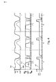
図3には、時間の経過につれた3つのダイアグラムが示されている。上のダイアグラムは、平面での通常の歩行中の時間に亘る膝角度KAおよび足首トルクAMを示す。真中のダイアグラムは、通常の歩行中の時間に亘る屈曲制動FDおよび伸展制動EDを示し、下のダイアグラムは、各々の時点における弁の位置VPを示す。これらのダイアグラムは、人工膝関節としての関節装置の実施の形態に関して示されている。ダイアグラムは、踵が接地する時点、すなわち、いわゆる「ヒール・ストライク」の時点で始まる。膝角度KAは180°であり、足首トルクAMは、平面方向に作用し、かくして、水平線の下に延びている。足首トルクAMがプラスになる時点まで、屈曲制動は高く、伸展制動は低い。次に、伸展制動は、ほぼ、屈曲制動FDのレベルに上昇され、前方への新たなスイングまで、そこに留まる。屈曲制動FDは、前足の離地の時点、すなわちいわゆる「トゥオフ」まで高いままである。次に、屈曲制動FDを低下させる。その目的は、後方への下腿のスイングを可能にするためである。屈曲の最大値の直前まで、屈曲制動は低いままであり、屈曲の最大値の、すなわち最小の膝角度KAの達成直前に、屈曲制動を再度増加させる。その目的は、一方では、屈曲動作を制動するためであり、他方では、意図されない座屈に対する最大限の安全をできる限り早急に得るためである。同時に、伸展制動EDを減少する。その目的は、下腿および義足足部のできる限りスムーズな前進を可能にするためである。立脚相の間に、弁位置VPは、受動的屈曲が生じる位置Cにある。屈曲最大値の始まりの直前に、切換手段60を、位置Aに移動させる。その目的は、屈曲支援を提供するためである。所定の膝角度が達成されるや否や、屈曲支援を形成する。制御された伸展制動EDは、いわゆる「踵挙上」の回避を引き起こす。能動屈曲支援を、足首トルクAMの経過に基づいて認識する。 FIG. 3 shows three diagrams over time. The upper diagram shows knee angle KA and ankle torque AM over time during normal walking in the plane. The middle diagram shows the flexion braking FD and the extension braking ED over time during normal walking, and the lower diagram shows the valve position VP at each time point. These diagrams are shown for an embodiment of a joint device as an artificial knee joint. The diagram begins at the point where the heel touches the ground, ie the so-called “heel strike”. The knee angle KA is 180 °, and the ankle torque AM acts in the plane direction and thus extends below the horizontal line. Up to the point where the ankle torque AM becomes positive, flexural braking is high and extension braking is low. Next, extension braking is raised to approximately the level of flexion braking FD and remains there until a new forward swing. The flexural braking FD remains high until the point of departure of the forefoot, ie the so-called “toe off”. Next, the bending brake FD is lowered. The purpose is to allow the lower leg to swing backwards. Until just before the maximum value of flexion, the flexural braking remains low and just before reaching the maximum value of flexion, ie the minimum knee angle KA, the flexural braking is increased again. The purpose is on the one hand to brake the bending movement and on the other hand to obtain the maximum safety against unintentional buckling as soon as possible. At the same time, the extension braking ED is reduced. The purpose is to allow as smooth advancement of the lower leg and prosthetic leg as possible. During the stance phase, the valve position VP is in position C where passive bending occurs. The switching means 60 is moved to the position A immediately before the start of the bending maximum value. The purpose is to provide bending support. As soon as a predetermined knee angle is achieved, flex support is formed. The controlled extension braking ED causes the so-called “lifting” avoidance. The active bending support is recognized based on the progress of the ankle torque AM.
弁40,50および切換手段60による液圧ユニット10の正確な制御を保証するために、個々の構成要素をモニタするセンサが設けられている。膝角度センサおよび足首トルクセンサのほかに、軸力センサも設けられていてもよい。制御を、例えば、関節角速度の観察によって、行なうことができる。関節角速度の転換点では、能動的な屈曲支援を、所定の期間、弁位置Aによって活動化する。屈曲弁50を、低い値に設定し、かつ、所定の関節角度を越えたとき、支援をオフに切り換え、切換手段を位置Cに移動させる。
In order to ensure accurate control of the
制御過程の変形例が、図4に示されており、この図には、伸展補助装置による能動的な支援を用いた支援が示されている。足部の持ち上げ(このことは、足首トルクAMで認識される)まで、制御は、図3に示すように推移する。持ち上げ後に、切換手段60のための位置Cへ再度移動する代わりに、弁位置Bを占め、かつ、伸展制動EDを増加させる。切換手段60の弁位置Bで、伸展を支援し、すなわち、膝角度速度を減少させ、回転方向を反転させる。伸展支援のスムーズな接続のために、伸展弁40を適切な時点で閉じ、かつ、再度開くことができる。伸展支援の、スムーズなオフへの切換を、屈曲弁50を閉じることによって達成する。
A modification of the control process is shown in FIG. 4, which shows assistance using active assistance by the extension assistance device. Control continues as shown in FIG. 3 until the foot is lifted (this is recognized by the ankle torque AM). Instead of moving again to the position C for the switching means 60 after lifting, it occupies the valve position B and increases the extension braking ED. At the valve position B of the switching means 60, extension is supported, that is, the knee angular velocity is reduced and the direction of rotation is reversed. For smooth connection of extension support, the
図5には、階段の上りに関するダイアグラムが示されている。足首トルクは存在していない。足部を持ち上げた後、膝角度KAが減少する。このことを容易にするために、伸展制動EDを低減し、切換手段60は、位置Aに移動する。その目的は、屈曲支援を引き起こすためである。屈曲制動FDは、更に、低いままである。伸展制動EDを、能動的な屈曲の期間の間、同様に、減少させる。続いて、切換手段60を位置Cへ移動させる。その目的は、膝角度KAが最小になるまで、屈曲動作の制動による受動的な屈曲を達成するためである。最終的に、切換手段60を弁位置Bに移動させる。この弁位置によって、能動的な伸展を達成する。それ故に、支援が圧力供給手段20によって作動することができる。切換手段60の切換時間中に、伸展制動EDを再度増加させる。能動的な伸展が変換される位置Bでは、伸展制動EDを減少させる。その目的は、支援の完全な有効性を保証するためである。屈曲制動FDを、患者自らの身体を持ち上げる間に、膝角度KAに従ってゆっくりと増大させる。このことによって、支援トルクが、前のトルクより小さくなり、かつ、伸展止めへの急停止を回避する。更に、ほとんど伸展した膝関節では、伸展制動EDを増加させる。その目的は、急停止を同様に制動するためである。 FIG. 5 shows a diagram relating to ascending the stairs. There is no ankle torque. After lifting the foot, the knee angle KA decreases. In order to facilitate this, the extension braking ED is reduced and the switching means 60 moves to position A. The purpose is to cause bending support. The flexural braking FD remains low further. The extension braking ED is similarly reduced during the period of active bending. Subsequently, the switching means 60 is moved to the position C. The purpose is to achieve passive flexion by braking the flexion motion until the knee angle KA is minimized. Finally, the switching means 60 is moved to the valve position B. This valve position achieves active extension. Therefore, the assistance can be activated by the pressure supply means 20. During the switching time of the switching means 60, the extension braking ED is increased again. In position B where the active extension is converted, the extension braking ED is decreased. The purpose is to ensure the full effectiveness of the support. The flexural braking FD is slowly increased according to the knee angle KA while lifting the patient's own body. This makes the support torque smaller than the previous torque and avoids a sudden stop to the extension stop. Furthermore, the extension braking ED is increased at the knee joint almost extended. The purpose is to brake sudden stops as well.
図5aには、図5に示したタイミング図の変形例が示されている。制御手段は、或る段を上がることが意図される状況を認識する。位置Cから始まって、切換手段60を所定の膝角度から位置Aへ移動させる。その目的は、能動的な屈曲制動を達成するためである。従って、患者は、支援を受けて、人工関節を装着した脚を、段のために屈曲する。かくして、階段の段の下縁に引っ掛からないように、義足足部を後方にスイングすることができる。能動的な屈曲制動の有効性を保証するために、屈曲制動FDを減少させる。伸展制動は、高い出力レベルにとどまっている。 FIG. 5a shows a modification of the timing diagram shown in FIG. The control means recognizes the situation intended to go up a certain stage. Starting from the position C, the switching means 60 is moved from the predetermined knee angle to the position A. The purpose is to achieve active flexural braking. Thus, with assistance, the patient bends the leg with the prosthetic joint for the step. Thus, the prosthetic leg can be swung backward so as not to be caught by the lower edge of the step of the stairs. In order to ensure the effectiveness of active flex braking, the flex braking FD is reduced. Extension braking remains at a high output level.
膝角度KAの所定の目標角度から上では、屈曲支援をオフに切り換え、切換手段60は、位置Cへ戻る。屈曲制動FDおよび伸展制動FDは変化されないままである。最大膝角度に到達直後に、屈曲制動を増加させる。その目的は、最大膝角度KAを制限するためである。最大膝角度に到達し、かつ、足部を接地した後に、伸展支援を作動させ、かつ、切換手段60を弁位置Bに移行する。同時に、伸展制動EDを減少させる。その目的は、持ち上げ動作の完全な支援を保証するためである。屈曲制動を高いレベルで維持するのは、例えば、患者の転倒を防止するためである。患者自らの身体を持ち上げる際に、膝角度KAに従って、伸展制動EDをゆっくり増加させる。その目的は、支援トルクをポンプ21または蓄圧器23によって小さくするためであり、かつ、伸展止めへの急停止を回避するためである。最大膝角度に到達した後で、支援をオフに切り換え、かつ、弁位置Bに切り換える。 Above the predetermined target angle of the knee angle KA, the bending support is switched off, and the switching means 60 returns to the position C. The flexion braking FD and the extension braking FD remain unchanged. Immediately after reaching the maximum knee angle, increase flexural braking. The purpose is to limit the maximum knee angle KA. After reaching the maximum knee angle and touching the foot, the extension support is activated and the switching means 60 is shifted to the valve position B. At the same time, the extension braking ED is decreased. The purpose is to ensure full support for the lifting operation. The reason why the flexural braking is maintained at a high level is, for example, to prevent the patient from falling. When lifting the patient's own body, the extension braking ED is slowly increased according to the knee angle KA. The purpose is to reduce the assist torque by the pump 21 or the pressure accumulator 23 and to avoid a sudden stop to the extension stop. After reaching the maximum knee angle, the support is switched off and switched to valve position B.
図6には、能動的な屈曲支援の変形例が湿されている。液圧ユニット10および切換手段60は、実質的に、図2の液圧ユニットおよび切換手段に対応している。しかしながら、圧力供給手段20は、異なる方法で、他の構成要素と結合されている。ポンプ21は、蓄圧器23が圧力媒体を供給することができるように、2方向に作動液を供給することができるポンプとして形成されている。蓄圧器23は、分岐管を介して、ポンプ21と接続されている。このことによって、蓄圧器23への別の加圧を行なうことができる。蓄圧器23から圧力媒体を開放するとき、すなわち、作動液を蓄圧器23から液圧ユニット10の方向に運ぶとき、ポンプ21は、モータにより、圧力を更に増加させることができる。この場合、2つの異なった圧力を実現することが可能である。何故ならば、圧力支援が、通常では、伸展支援よりも少ない圧力を必要とするからである。更に、ポンプ21をジェネレータとして使用することが可能である。蓄圧器23の中の圧力が、液圧ユニット10の液圧シリンダ内で必要とされるよりも著しく高いとき、ポンプ21をジェネレータモードで動作させることができる。その目的は、減圧を引き起こし、同時に、液圧エネルギの一部を電気エネルギに変換するためである。そうでない場合には、液圧エネルギは、各々の弁40,50で失われるであろう。何故ならば、圧力を常にスムーズに接続することが意図されるからである。ジェネレータエネルギの放出の制御によって、可変の圧力差で動作することができる。このことによって、動力損失および熱への圧力エネルギの変換が最小限に抑えられる。
In FIG. 6, a modification of active bending support is moistened. The
更に、図6に示す回路を用いて、弁40,50における損失の増加をもたらすことなく、蓄積器23内の圧力を著しく増大させることができる。従って、蓄積器23は、関節装置の動作からのより多くのエネルギを蓄積することができる。作動液を蓄圧器23から液圧ユニットへ通す際に、ポンプ21を、ジェネレータモードで作動させることができる。その目的は、所望の作動液へ適合させるためである。圧力の低下を、蓄積しかつポンプの動作のために使用することができる、電気エネルギへの変換によって、行なう。能動的支援が伸展動作のために不要であるときは、制御手段60のこの位置を、蓄圧器23に作動液を加えるためにも使用することができる。この目的のために、蓄圧器23内の圧力を、圧力センサ22によって測定し、同時に、液圧シリンダ11の圧力を、伸展室15の出口で測定する。圧力センサ72は、蓄圧器23と伸展室15の間の圧力差があるか否かを示す。圧力差に従って、屈曲弁40を調整する。圧力が蓄圧器23内に存在しないときは、補装具使用者は、伸展弁40が完全に開く際に、全然抵抗を受けないし、転倒するだろう。従って、屈曲弁40を、圧力に従って、関節装置の使用者が階段を下りる際に、常に同じ抵抗を感じるように、切り換える。同じことが、傾斜面上での下降にも当てはまる。蓄圧器23には、下方への歩行毎に、続けてエネルギを供給し、従って、圧力を加えるのである。
In addition, the circuit shown in FIG. 6 can be used to significantly increase the pressure in the accumulator 23 without increasing the losses in the
別の選択として、別の蓄圧器が設けられていてもよい。この蓄圧器は、非常に高い圧力のために設計されており、蓄圧器23が関節装置の正常な動作のために必要とする圧力よりも高いのである。追加の蓄圧器に、階段の上り下りによって、非常に高く圧力媒体を供給することができる。それ故に、エネルギ蓄積能力が増加する。ジェネレータモードで電気エネルギを発生させることができるように、ポンプ21が空気圧式のモータとして動作するという可能性がある。追加の蓄圧器からも、エネルギを、制御下でも、蓄圧器23へ放出することができる。その目的は、圧力の蓄えを作り出すことができるためである。 As another option, another pressure accumulator may be provided. This accumulator is designed for very high pressure, and the accumulator 23 is higher than the pressure required for the normal operation of the joint device. The additional accumulator can be supplied with a very high pressure medium by going up and down the stairs. Therefore, the energy storage capacity is increased. There is a possibility that the pump 21 operates as a pneumatic motor so that electric energy can be generated in the generator mode. Energy can be released from the additional accumulator to the accumulator 23, even under control. The purpose is to create a pressure reserve.
図7には、図6の変形例が示されている。この変形例は、ポンプ21またはジェネレータと蓄圧器23との間に切換弁28が設けられており、この切換弁によって、蓄圧器23を、残りの構成要素から分離することが可能であることを意図する。このことによって、ポンプ21を蓄圧器23に独立して作動させることが可能である。この目的のために、他の逆止弁29が設けられており、この逆止弁は、既存の逆止弁24と平行に設けられている。両方の逆止弁24,29は、ポンプ21から作動液が蓄積器16に供給されることを阻止する。
FIG. 7 shows a modification of FIG. In this modified example, a switching
図8には、図7に示した実施の形態の変形例が示されている。図8に示した実施の形態は、切換弁手段290が、逆止弁29に平行に液圧導管に設けられていることを意図する。この切換弁手段290は、切換位置Aにあるとき、逆止弁29を迂回することを可能にする。この切換位置は示されている。弁手段290の切換位置Bには、バイパスが遮断されている。その目的は、対応の圧力勾配が弁29にあるとき、作動液が逆止弁29を通って流れることができないためである。この追加の弁手段290は、圧力媒体が蓄圧器23に充填されているとき、膝の屈曲により強制される液圧流が、ポンプ21を介して、ジェネレータモードで発電のために用いることができるために、使用される。この目的のために、弁手段290,28,60を対応の位置へ移動しなければならない。その目的は、ポンプ21を、ジェネレータモードで屈曲の際に作動液によって駆動することができるためである。ジェネレータモードによって、必要な場合には追加の屈曲制動を、機械エネルギおよび液圧エネルギを電気エネルギに変換することによって、達成する。 FIG. 8 shows a modification of the embodiment shown in FIG. The embodiment shown in FIG. 8 contemplates that the switching valve means 290 is provided in the hydraulic conduit parallel to the check valve 29. This switching valve means 290 makes it possible to bypass the check valve 29 when in the switching position A. This switching position is shown. The bypass is blocked at the switching position B of the valve means 290. The purpose is that hydraulic fluid cannot flow through the check valve 29 when the corresponding pressure gradient is in the valve 29. This additional valve means 290 allows the hydraulic flow forced by the knee flexion to be used for power generation in the generator mode via the pump 21 when the pressure medium is filled in the accumulator 23. Used. For this purpose, the valve means 290, 28, 60 must be moved to the corresponding positions. The purpose is that the pump 21 can be driven by hydraulic fluid during bending in the generator mode. With generator mode, additional flexural braking is achieved if necessary by converting mechanical and hydraulic energy into electrical energy.
図9には、個々の弁または制御手段の位置ならびに歩行の過程に亘る位置の変化が表形式で示されている。表の上方には、平面での歩行のための歩行周期が示されている。通常の膝角度KAは、最大限に伸展した位置で約180°と、最大限に屈曲した位置での120°との間に延びている。歩行周期は、複数の相に区分される。最重要な区分を、立脚相と遊脚相の間で行なう。踵接地、すなわち、人工足関節の着地(この着地には立脚相における屈曲が続く)で始まる膝角度曲線が示されている。膝関節が安定的な位置にある第1の接地後に、体重による荷重によって膝関節を内側に屈曲させる。荷重に直ぐ続いて生じる屈曲は、地面との接触による衝撃を制動する。初期の接地および荷重応答を、期間1ないし4で行なう。続いて、膝関節の伸展を開始する。その目的は、改善された安定を達成するためである。続いて、伸展を完了する。これは、第6の期間における中期のおよび周期の立脚相である、続いて、いわゆるプレスイング期7で、膝関節の受動的な屈曲を行なう。プレスイング期7の終わりで、いわゆる「トゥオフ」すなわち地面からの足部の持ち上げを行なう。その目的は、脚がプレスイングすることができるためである。初期の遊脚相では、次に、続いて、最大限の屈曲を達成する。中期の遊脚相9では、脚のプレスイングを達成し、終期の遊脚相では、膝関節の伸展を促進する。その目的は、最大限の膝角度を達成し、かつ、立脚期への準備をするためである。
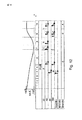
FIG. 9 shows the position of the individual valves or control means and the change in position over the course of walking in tabular form. Above the table, the walking cycle for walking on a plane is shown. The normal knee angle KA extends between about 180 ° at the maximum extended position and 120 ° at the maximum bent position. The walking cycle is divided into a plurality of phases. The most important division is made between the stance phase and the swing phase. Shown is a knee angle curve that begins with heel contact, ie, the landing of an artificial ankle joint, which is followed by flexion in the stance phase. After the first ground contact where the knee joint is in a stable position, the knee joint is bent inward by a load due to weight. The bending that occurs immediately following the load brakes the impact due to contact with the ground. Initial ground contact and load responses are made in
動作のこの経過の下に記載された表では、能動的な伸展支援機能を有する状況および能動的な伸展支援機能を有しない状況に関する関節装置の液圧回路の個々の要素が示されている。終期の立脚相まで、切換手段60が中間位置Cに設けられており、最大限屈曲までの終期立脚相に関しては、切換手段を弁位置Aにもたらす。その目的は、屈曲開始の際に支援を可能にするためである。最大屈曲の達成後に、伸展補助装置機能なしに、すなわち、伸展支援なしに、蓄圧器23またはポンプ21による支援を再度オフに切り換える。伸展支援の際には、最大屈曲の達成後に、(切換手段を)弁位置Bに切り換える。その目的は、伸展支援を達成するためにある。 In the table described under this course of operation, the individual elements of the hydraulic circuit of the joint device are shown for situations with active extension support functions and conditions without active extension support functions. The switching means 60 is provided in the intermediate position C until the final stance phase, and the switching means is brought to the valve position A for the final stance phase until the maximum bending. The purpose is to enable support at the start of bending. After the maximum bending is achieved, the support by the pressure accumulator 23 or the pump 21 is switched off again without the extension assisting device function, ie without extension support. When the extension is supported, the switch position is switched to the valve position B after the maximum bending is achieved. The purpose is to achieve extension support.
この場合、伸展弁40は、立脚相の間に、主に閉じたままである。終期の立脚相の初めになってはじめて、伸展弁が開き、すべての屈曲期の間、実質的に開いたままである。終期の遊脚相の間にはじめて、伸展弁を再度閉じる。その目的は、伸展止めを回避するためである。立脚相の間の高い伸展制動は、立脚相での伸展の間の伸展への急停止を阻止する。
In this case, the
伸展弁50は、まず、主に閉じられている。その目的は、立脚相での屈曲を制動するためである。立脚相での伸展後には、屈曲を可能にするため、屈曲制動を減少させる。屈曲の開始前に、屈曲制動を最大限減少させる。何故ならば、ここでは、膝関節を、地面(床)反力によって停止に保つからである。伸展支援なしに、遊脚相で屈曲制動を増加させる。その目的は、人工足部の過旋回(Ueberschwingen)およびいわゆる「踵挙上」を回避するためである。屈曲制動は高いレベルのままである。その目的は、つまずきを阻止することができるためである。伸展補助装置機能を有する屈曲弁は、屈曲期の間の制動の増加を意図しない。何故ならば、ここでは、「踵挙上」を回避する必要がないからである。その理由は、踵挙上を、伸展支援を作動させることによって行なうからである。屈曲方向における制動は、伸展補助装置機能を有しない制動と比較して長い時間、低いままである。その目的は、伸展支援を可能にするためである。続いて、屈曲制動を再度増加させる。その目的は、つまずきを阻止することができるためである。
First, the
弁290および28を有する図8に示した変形例については、支援または蓄積器への圧力媒体の供給の際に損失を被らないために、弁290が閉じたままであることが意図されている。終期の遊脚相の終わりに、弁を開くことができる。その目的は、作動液の流れをポンプ21によって、ジェネレータモードで導き、従ってまた、機械エネルギを電気エネルギに変換するためである。弁28を終期の遊脚相の間に閉じる。その目的は、圧力媒体を充填した蓄積器23では、強制された作動液の流れを、ポンプ21のジェネレータモードで発電のために使用するためである。
For the variation shown in FIG. 8 with
図10は、急斜面の昇りの際の回路を示す。ここでは、伸展支援機能によって操作を行なうことは有意義である。終期の立脚相まで、弁60は、位置Bにある。その目的は、患者が階段の段をより容易に上ることができるように、あるいは、傾斜面をより容易に上がるように、伸展支援を保証するためである。屈曲支援を、「トゥオフ」後の屈曲開始の際に、行ない、伸展支援を、終期の遊脚相で行なう。伸展弁40は、まず、実質的に開いたままである。その目的は、伸展支援が最大限働くように、伸展方向における低い制動を保証するためである。伸展止めへの到達前に、伸展弁40の閉鎖従ってまた伸展制動の増加が必要である。その目的は、伸展止めへの急停止を回避するためである。切換弁60の切換時点で、伸展弁の短時間の閉鎖は、激しい衝撃を回避するために、意味がある。代わりに、屈曲弁50をこれらの時点で短時間閉じることができる。これとは別に、屈曲弁50は、動作の全期間に亘って実質的に開いている。その目的は、その目的は、最小の制動および最大の支援を可能にするためである。
FIG. 10 shows the circuit during the ascent of the steep slope. Here, it is meaningful to perform an operation using the extension support function. The
図11には、伸展補助装置機能による急斜面の下降に関するダイアグラムが示されている。全立脚相に亘って、切換弁は位置Cにとどまっており、伸展支援または屈曲支援は生じない。初期の遊脚相ではじめて、切換弁は、屈曲支援を達成するために、位置Bを占める。伸展弁は、立脚相で閉じられており、あるいは、急な下り坂が最早ない場合でも、高い伸展制動を保証するために、高い制動を有する。最大の屈曲への到達後に、伸展を可能にするために、伸展制動を減少させる。従って、弁40を開く。遊脚相の終わりで、伸展を再度増加させる。その目的は、伸展止めへの急停止を回避するためである。
FIG. 11 shows a diagram relating to the steep slope descending by the extension assisting device function. During the entire stance phase, the switching valve remains in position C and no extension or flexing support occurs. Only in the early swing phase, the switching valve occupies position B in order to achieve bending support. The extension valve is closed in the stance phase or has high braking to ensure high extension braking even when there is no longer a steep downhill. After reaching maximum flexion, the extension braking is reduced to allow extension. Therefore, the
屈曲弁50は、立脚相の間、下方への移動の際に屈曲を制動するために、増大した屈曲抵抗を有する。続いて、屈曲動作を可能にするために、屈曲弁50をゆっくりと開く。遊脚相では、制動は低いままである。その目的は、望ましい場合には、伸展支援を可能にするためである。代わりに、中期の遊脚相の領域であるように、屈曲制動を増加させることもできる。終期の遊脚相の領域では、再度、最大の屈曲制動を行なう。
The
図12には、回路装置および切換経過(Schaltverlauf)が示されている。図11に示す急な下りの際に、切換経過が生じえるのは、蓄圧器23に圧力媒体を供給すべきとき、または電気エネルギをポンプ21のジェネレータモードで発生させるべきとき、である。切換弁60を立脚相の間に位置Aに移動する。その目的は、エネルギを蓄積器23に運ぶことができるためである。このことを行なうことが有用であるのは、これによって、蓄圧がピストン圧力を上回らない場合のみである。これが万一当てはまるならば、図11に示す切換方式を適用すべきだろう。
FIG. 12 shows a circuit device and a switching process (Schaltverlauf). The switching process can occur during the steep descent shown in FIG. 11 when the pressure medium is to be supplied to the accumulator 23 or when electric energy is to be generated in the generator mode of the pump 21. The switching
図11とは異なり、図12に示す制御では、伸展弁を、既に、終期の立脚相で開き、かつ伸展制動を減少させる。全体の初期の遊脚相に亘って、伸展弁は開いたままである。伸展弁を、中期の遊脚相ではじめて再度閉じる。その目的は、遊脚相の終わりで、急停止を回避すべく、伸展制動を増加させるためである。屈曲弁は、全体の動作の経過に亘って開いたままである。その目的は、エネルギを蓄積器23に導くためである。弁の位置を、蓄積器23とピストンとの間の圧力差に適合するほうがよい。蓄積器23が空であるとき、より高い屈曲制動があるように、屈曲弁50を調整することができる。遊脚相では、屈曲制動を同様に低く保たねばならない。その目的は、伸展支援が望ましい場合には、伸展支援を可能にするためである。切換弁290を立脚相の間に開けるのは、作動液の流れをジェネレータによって発電のために使用することができるためである。弁28は閉じたままである。伸展期では、弁290を閉じる。その目的は、伸展支援を蓄圧器23によって可能にするためである。
Unlike FIG. 11, in the control shown in FIG. 12, the extension valve is already opened in the final stance phase and extension braking is reduced. The extension valve remains open throughout the entire initial swing phase. The extension valve is closed again only during the mid-swing phase. The purpose is to increase extension braking to avoid a sudden stop at the end of the swing phase. The flex valve remains open over the course of the entire operation. The purpose is to guide energy to the accumulator 23. It is better to match the position of the valve to the pressure difference between the accumulator 23 and the piston. The
図13には、歩行周期に関するタイミンダイアグラムが示されている。タイミングダイアグラムには、時間tに亘っての膝角度KAが示されている。膝角度KAは、歩行終期の初めに、すなわち、踵接地つまりいわゆる「ヒールス・トライク」の際に、立脚相における初期の屈曲に基づき、0°よりも大きく、後続の立脚相区分に亘って、0°で一定であり、約1.1秒の後には増加する。膝角度KAは、立脚相の終わりで、いわゆる「トゥオフ」後に、t=1.35秒では、約55°の最大屈曲まで増加し続ける。最大の膝角度KAの達成後、運動の反転を行なう。下腿の構成要素を前方に移動させる。その目的は、膝角度KAが伸展動作により再度減少し、かつ、遊脚相の終わりに、最大のまたはほぼ最大の伸展において、0°の膝関節KAで終了するためである。他の図の描写とは異なり、膝角度KAには、図13では、伸展位置で0°が付されている。 FIG. 13 shows a timing diagram regarding the walking cycle. In the timing diagram, the knee angle KA over time t is shown. The knee angle KA is greater than 0 ° at the beginning of the end of gait, i.e., during heel contact or so-called “Health Strike”, based on the initial flexion in the stance phase, over the subsequent stance phase section, It is constant at 0 ° and increases after about 1.1 seconds. The knee angle KA continues to increase at the end of the stance phase, after a so-called “toe-off”, until a maximum flexion of about 55 ° at t = 1.35 seconds. After achieving the maximum knee angle KA, the movement is reversed. Move the lower leg component forward. The purpose is that the knee angle KA is again reduced by the extension movement and ends at the knee joint KA of 0 ° at the end of the swing phase, at the maximum or almost maximum extension. Unlike the depiction of the other figures, the knee angle KA is given 0 ° in the extended position in FIG.
図13から、更に、支援の屈曲トルクFMを屈曲の直前に加えることが見て取れる。膝角度曲線に基づいて、膝の屈曲を引き起こすためには屈曲トルクFMが十分でないことが分かる。むしろ、屈曲トルクFMのレベルは、使用者が屈曲のための支援のみを提供し、かつ、屈曲を独立的に引き起こさないように、選択されている。このことは、膝角度KAが最大の屈曲トルクFMが全期間に亘って不変のままであることから分かる。既に屈曲のはじめに、すなわち、膝屈曲の方向での膝角度の変化のはじめの前に、屈曲トルクFMのレベルを低下させる。その目的は、膝関節の余りに容易な屈曲に達することを阻止するためである。このことは、結果として膝関節の安定性の欠如をもたらすだろう。屈曲トルクを一時的に加えることは、より少ないエネルギを準備すればよいという利点を有する。同様に、膝関節は、立脚相の間に、主に屈曲支援なしのままである。それ故に、望ましくない屈曲に対する高い安全性が保証されている。屈曲のためのトリガトルクの減少を意味することができる支援によって、安定的な構造を選択することができる。安定的な構造、すなわち、個々の構成要素の互いの割り当ての故に、患者への荷重の増加をもたらすことなく、安定性の増加を供給することができる。 It can further be seen from FIG. 13 that the assist bending torque FM is applied just before the bending. Based on the knee angle curve, it can be seen that the bending torque FM is not sufficient to cause the knee to bend. Rather, the level of flexion torque FM is selected so that the user provides only assistance for flexion and does not cause flexion independently. This can be seen from the fact that the bending torque FM with the maximum knee angle KA remains unchanged over the entire period. Already at the beginning of the flexion, ie before the start of the change of the knee angle in the direction of the knee flexion, the level of the flexion torque FM is reduced. Its purpose is to prevent the knee joint from reaching too easy flexion. This will result in a lack of stability of the knee joint. Applying the bending torque temporarily has the advantage that less energy needs to be provided. Similarly, the knee joint remains largely unflexible during the stance phase. Therefore, a high safety against undesired bending is ensured. With assistance that can mean a reduction in trigger torque for bending, a stable structure can be selected. Because of the stable structure, i.e., the assignment of individual components to each other, increased stability can be provided without resulting in increased load on the patient.
「トゥオフ」後に、すなわち、約t=1.2秒の際に、支援の屈曲トルクが存在しない。むしろ、屈曲制動として作用しかつ膝関節の過度な屈曲を阻止する伸展トルクEMを印加する。伸展トルクEMの能動的な印加の代わりに、純粋に受動的な制動を行なうこともできる。同様に、システムからのエネルギを制動のために変換によって運び出すことも可能であり、屈曲トルクの印加のために必要なエネルギを少なくとも部分的に戻すことができる。伸展トルクEMを印加するとき、伸展トルクEMが印加される相が、膝関節の完全な伸展の前で終わる。 There is no assist flexion torque after “to-off”, ie at about t = 1.2 seconds. Rather, an extension torque EM that acts as a bending brake and prevents excessive bending of the knee joint is applied. Instead of active application of the extension torque EM, purely passive braking can also be performed. Similarly, energy from the system can be carried out by conversion for braking, and the energy required for application of bending torque can be at least partially returned. When applying the extension torque EM, the phase in which the extension torque EM is applied ends before full extension of the knee joint.
エネルギが、動作の際に使用者を支援するために、同じレベルか減少したレベルで、動作の解除を越えても、印加されたままであることは、可能であり、かつ意図される。供給したエネルギの比較的低いレベルは、メンテナンスなしの可能な使用時間を延長する。 It is possible and intended for energy to remain applied across the release of motion at the same or reduced level to assist the user in operation. The relatively low level of energy supplied extends the possible use time without maintenance.
図13に示したダイアグラムでは、更に、印加された出力Pおよびなされた仕事Wがプロットされている。モータで供給された出力Pは、膝の屈曲のはじめに上昇し、「トゥオフ」後に、出力過剰がある。このことは、モータによる出力を供給する必要のないことを意味する。膝角度の最大値に達した後に、出力Pが再度プラスになるように、伸展のために、再度出力を必要とする。 In the diagram shown in FIG. 13, the applied output P and the work W done are also plotted. The output P supplied by the motor rises at the beginning of the knee flexion and there is an excessive output after "toe off". This means that it is not necessary to supply the output from the motor. After reaching the maximum value of the knee angle, the output is required again for the extension so that the output P becomes positive again.
図13を参照して説明した制御は、液圧式の駆動手段によって、実施可能であるだけではない。屈曲トルクおよび伸展トルクを電動モータによって、直に、必要な場合には適切な伝動装置を介して、印加する。終わりで動作を制御するために、モータをジェネレータモードに切り換えることができる。発生した電気エネルギを蓄積器またはコンデンサに蓄積することができる。その目的は、エネルギを所定の時間に取り出すことができるためである。 The control described with reference to FIG. 13 is not only executable by hydraulic drive means. The bending torque and extension torque are applied directly by the electric motor, if necessary, via a suitable transmission. To control the operation at the end, the motor can be switched to generator mode. The generated electrical energy can be stored in an accumulator or capacitor. The purpose is that energy can be extracted at a predetermined time.
1 関節装置
2 上部
3 下部
4 取付手段
5 取付手段
10 液圧ユニット
12 ピストン
15 屈曲室
20 圧力供給手段
21 ポンプ
23 蓄圧器
60 制御手段
DESCRIPTION OF
図13を参照して説明した制御は、液圧式の駆動手段によって、実施可能であるだけではない。屈曲トルクおよび伸展トルクを電動モータによって、直に、必要な場合には適切な伝動装置を介して、印加する。終わりで動作を制御するために、モータをジェネレータモードに切り換えることができる。発生した電気エネルギを蓄積器またはコンデンサに蓄積することができる。その目的は、エネルギを所定の時間に取り出すことができるためである。
以下に、本願出願の当初の特許請求の範囲に記載された発明を付記する。
[1] 装具用のまたは補装具用の関節装置であって、上部(2)と、該上部に喋着された下部(3)と、前記関節装置(1)を使用者に取り付けるための取付手段(4,5)とを有し、前記上部(2)と前記下部(3)との間に少なくとも1つの液圧ユニット(10)を具備し、該液圧ユニットは、伸展室(14)と屈曲室(15)を有するハウジング(11)の中で可動なピストン(11)を有し、該ピストンは、前記上部(2)または前記下部(3)に連結されており、前記液圧ユニットには、ポンプ(21)と蓄圧器(23)を有する圧力供給手段(20)が割り当てられており、該圧力供給手段を介して、制御手段(60)により制御しつつ、前記ピストン(12)に圧力を印加してなる関節装置において、
前記蓄圧器(23)は、前記ポンプ(21)と駆動式に連結されていることを特徴とする関節装置。
[2] 前記ポンプ(21)は、ジェネレータモードで操作可能であることを特徴とする請求項1に記載の関節装置。
[3] 作動液を、前記蓄圧器(23)から前記ポンプ(21)を通って前記液圧ユニット(10)を導くことができることを特徴とする[1]または[2]に記載の関節装置。
[4] 前記ポンプ(21)は、前記蓄圧器(23)内の圧力に適合可能である調整可能な吐出量を有することを特徴とする[1]ないし[3]のいずれか1項に記載の関節装置。
[5] 前記蓄圧器(23)は、圧力導管を介してのみ、前記ポンプ(21)によって前記液圧ユニット(10)に接続されていることを特徴とする[1]ないし[4]のいずれか1項に記載の関節装置。
[6] 関節角度、絶対角度、前記上部または前記下部に作用する軸力、関節トルクおよび/または遠位の接続構成要素に作用するトルクを検出する手段(7,8)が、前記制御手段(60)に割り当てられていることを特徴とする[1]ないし[5]のいずれか1項に記載の関節装置。
[7] 前記関節装置は、補装具用関節装置または装具用関節装置として形成されていることを特徴とする[1]ないし[6]のいずれか1項に記載の関節装置。
[8] 作動液を計量配分して供給または排出するための少なくとも1つに弁ユニット(26,28;40,50)が、前記蓄圧器(23)に割り当てられていることを特徴とする[1]ないし[7]のいずれか1項に記載の関節装置。
[9] 前記ポンプ(21)および前記液圧ユニット(10)は、前記蓄圧器(23)に液圧連通していることを特徴とする[1]ないし[8]のいずれか1項に記載の関節装置。
[10] 異なった圧力レベルおよび/または容量を有する複数の蓄圧器(23)が設けられていることを特徴とする[1]ないし[9]のいずれか1項に記載の関節装置。
[11] 装具用のまたは補装具用の関節装置を制御するための方法であって、該関節装置は、上部(2)と、該上部に喋着された下部(3)と、前記関節装置(1)を使用者に取り付けるための取付手段(4,5)と、前記関節装置にトルクを印加するための駆動手段とを有し、
屈曲または伸展前に、前記関節装置に、屈曲または伸展をもたらすレベルより低い屈曲
トルクまたは伸展トルクを印加することを特徴とする方法。
[12] 前記関節装置を屈曲するとき、あるいは該関節装置を屈曲する前に、屈曲トルクを減少させることを特徴とする[11]に記載の方法。
[13] 前記屈曲トルクを、歩行周期の時間の5%と40%の間、特に歩行周期5%と20%の間である時間空間に、屈曲の前に印加することを特徴とする[11]または[12]に記載の方法。
[14] 歩行状況に従って、高さの異なる屈曲トルクを供給することを特徴とする[11]ないし[13]のいずれか1項に記載の方法。
[15] 補装具構造に従って、高さの異なる屈曲トルクを供給することを特徴とする[11]ないし[14]のいずれか1項に記載の方法。
[16] 前記屈曲トルクを、所定の、決定された屈曲角度まで印加することを特徴とする請求項[11]ないし[15]のいずれか1項に記載の方法。
[17] 前記屈曲トルクの開始後に、受動的な制動を行ない、あるいは、前記ポンプ(21)をジェネレータモードで動作させることを特徴とする[11]ないし[16]のいずれか1項に記載の方法。
[18] 屈曲トルクまたは伸展トルクの印加を、屈曲動作または伸展動作のはじめを越えて維持することを特徴とする[11]ないし[17]のいずれか1項に記載の方法。
[19] 伸展トルクの減少を、伸展止めへの到達前に、開始することを特徴とする[11]ないし[18]のいずれか1項に記載の方法。
[20] 交互の階段上りの際に、前記圧力発生手段(20)は、力ベクトルが膝関節の回転軸の前で保持されるように、伸展トルクを印加することを特徴とする[11]ないし[19]のいずれか1項に記載の方法。
[21] 前記圧力発生手段(20)は、立脚相において、前記膝関節を、トルクで能動的に保持することを特徴とする[11]ないし[20]のいずれか1項に記載の方法。
[22]前記圧力発生手段(20)は、前記伸展トルクを、初期の遊脚相において、前記最大の屈曲トルクの達成まで増加させ、かつ、前記伸展トルクを動作の反転まで維持し、前記屈曲トルクを、屈曲角の減少につれて、再度減少させることを特徴とする[11]ないし[21]のいずれか1項に記載の方法。
The control described with reference to FIG. 13 is not only executable by hydraulic drive means. The bending torque and extension torque are applied directly by the electric motor, if necessary, via a suitable transmission. To control the operation at the end, the motor can be switched to generator mode. The generated electrical energy can be stored in an accumulator or capacitor. The purpose is that energy can be extracted at a predetermined time.
Hereinafter, the invention described in the scope of claims of the present application will be appended.
[1] A joint device for an orthosis or a prosthesis, the upper portion (2), a lower portion (3) attached to the upper portion, and an attachment for attaching the joint device (1) to a user Means (4, 5), comprising at least one hydraulic unit (10) between the upper part (2) and the lower part (3), the hydraulic unit comprising an extension chamber (14) And a movable piston (11) in a housing (11) having a bending chamber (15), the piston being connected to the upper part (2) or the lower part (3), the hydraulic unit The pressure supply means (20) having a pump (21) and a pressure accumulator (23) is allocated to the piston (12) while being controlled by the control means (60) via the pressure supply means. In the joint device formed by applying pressure to
The joint device characterized in that the pressure accumulator (23) is connected to the pump (21) in a driving manner.
[2] The joint device according to
[3] The joint device according to [1] or [2], wherein the hydraulic fluid can be guided from the pressure accumulator (23) through the pump (21) to the hydraulic unit (10). .
[4] The pump (21) according to any one of [1] to [3], wherein the pump (21) has an adjustable discharge amount that can be adapted to the pressure in the accumulator (23). Joint device.
[5] Any of [1] to [4], wherein the pressure accumulator (23) is connected to the hydraulic pressure unit (10) by the pump (21) only through a pressure conduit. The joint device according to
[6] Means (7, 8) for detecting a joint angle, an absolute angle, an axial force acting on the upper part or the lower part, a joint torque and / or a torque acting on a distal connecting component are the control means ( 60), the joint device according to any one of [1] to [5].
[7] The joint device according to any one of [1] to [6], wherein the joint device is formed as a joint device for a prosthesis or a joint device for a brace.
[8] A valve unit (26, 28; 40, 50) is assigned to the pressure accumulator (23) as at least one for distributing and supplying or discharging hydraulic fluid. [1] The joint device according to any one of [7].
[9] According to any one of [1] to [8], the pump (21) and the hydraulic unit (10) are in hydraulic communication with the accumulator (23). Joint device.
[10] The joint device according to any one of [1] to [9], wherein a plurality of pressure accumulators (23) having different pressure levels and / or capacities are provided.
[11] A method for controlling a joint device for a brace or a prosthesis, the joint device comprising an upper part (2), a lower part (3) attached to the upper part, and the joint apparatus (1) having attachment means (4, 5) for attaching to the user, and drive means for applying torque to the joint device;
Bending below the level that causes the articulation device to bend or extend prior to bending or extension
Applying a torque or an extension torque.
[12] The method according to [11], wherein the bending torque is reduced when the joint device is bent or before the joint device is bent.
[13] The bending torque is applied before bending in a time space between 5% and 40% of the time of the walking cycle, particularly between 5% and 20% of the walking cycle [11] ] Or the method according to [12].
[14] The method according to any one of [11] to [13], wherein bending torques having different heights are supplied according to a walking situation.
[15] The method according to any one of [11] to [14], wherein bending torques having different heights are supplied according to the prosthetic device structure.
[16] The method according to any one of [11] to [15], wherein the bending torque is applied up to a predetermined and determined bending angle.
[17] The passive motor according to any one of [11] to [16], wherein passive braking is performed after the bending torque is started, or the pump (21) is operated in a generator mode. Method.
[18] The method according to any one of [11] to [17], wherein the application of the bending torque or the extension torque is maintained beyond the beginning of the bending operation or the extension operation.
[19] The method according to any one of [11] to [18], wherein the reduction of the extension torque is started before reaching the extension stop.
[20] When alternately climbing stairs, the pressure generating means (20) applies an extension torque so that the force vector is held in front of the rotation axis of the knee joint [11]. Or the method according to any one of [19].
[21] The method according to any one of [11] to [20], wherein the pressure generating means (20) actively holds the knee joint with torque in a stance phase.
[22] The pressure generating means (20) increases the extension torque until the maximum bending torque is achieved in the initial swing leg phase, and maintains the extension torque until the reversal of the operation. The method according to any one of [11] to [21], wherein the torque is decreased again as the bending angle decreases.
Claims (22)
前記蓄圧器(23)は、前記ポンプ(21)と駆動式に連結されていることを特徴とする関節装置。 A joint device for a brace or a prosthesis, comprising an upper part (2), a lower part (3) attached to the upper part, and attachment means (4) for attaching the joint apparatus (1) to a user 5), and at least one hydraulic unit (10) is provided between the upper part (2) and the lower part (3), the hydraulic unit comprising an extension chamber (14) and a bending chamber A movable piston (11) in a housing (11) having (15), the piston being connected to the upper part (2) or the lower part (3); A pressure supply means (20) having a pump (21) and a pressure accumulator (23) is allocated, and the pressure is applied to the piston (12) while being controlled by the control means (60) via the pressure supply means. In the applied joint device,
The joint device characterized in that the pressure accumulator (23) is connected to the pump (21) in a driving manner.
屈曲または伸展前に、前記関節装置に、屈曲または伸展をもたらすレベルより低い屈曲トルクまたは伸展トルクを印加することを特徴とする方法。 A method for controlling a joint device for a brace or a prosthesis, the joint device comprising an upper part (2), a lower part (3) attached to the upper part, and the joint apparatus (1) Attachment means (4, 5) for attaching the user to the user, and drive means for applying torque to the joint device,
Before bending or stretching, applying a bending torque or stretching torque to the articulating device that is lower than a level that causes bending or stretching.
Applications Claiming Priority (2)
| Application Number | Priority Date | Filing Date | Title |
|---|---|---|---|
| DE102012013141.0A DE102012013141A1 (en) | 2012-07-03 | 2012-07-03 | Orthotic or prosthetic joint device and method for its control |
| DE102012013141.0 | 2012-07-03 |
Related Parent Applications (1)
| Application Number | Title | Priority Date | Filing Date |
|---|---|---|---|
| JP2015518888A Division JP2015521505A (en) | 2012-07-03 | 2013-06-26 | Prosthetic or prosthetic joint device and method for controlling the joint device |
Publications (2)
| Publication Number | Publication Date |
|---|---|
| JP2017159053A true JP2017159053A (en) | 2017-09-14 |
| JP6851886B2 JP6851886B2 (en) | 2021-03-31 |
Family
ID=48790319
Family Applications (2)
| Application Number | Title | Priority Date | Filing Date |
|---|---|---|---|
| JP2015518888A Pending JP2015521505A (en) | 2012-07-03 | 2013-06-26 | Prosthetic or prosthetic joint device and method for controlling the joint device |
| JP2017077565A Active JP6851886B2 (en) | 2012-07-03 | 2017-04-10 | Joint devices for orthoses or prosthetics and methods of controlling the joint devices |
Family Applications Before (1)
| Application Number | Title | Priority Date | Filing Date |
|---|---|---|---|
| JP2015518888A Pending JP2015521505A (en) | 2012-07-03 | 2013-06-26 | Prosthetic or prosthetic joint device and method for controlling the joint device |
Country Status (6)
| Country | Link |
|---|---|
| US (2) | US11096804B2 (en) |
| EP (1) | EP2869794B1 (en) |
| JP (2) | JP2015521505A (en) |
| CN (1) | CN104602650B (en) |
| DE (1) | DE102012013141A1 (en) |
| WO (1) | WO2014005679A2 (en) |
Families Citing this family (32)
| Publication number | Priority date | Publication date | Assignee | Title |
|---|---|---|---|---|
| US10842653B2 (en) | 2007-09-19 | 2020-11-24 | Ability Dynamics, Llc | Vacuum system for a prosthetic foot |
| CN104887364B (en) * | 2014-03-03 | 2018-11-02 | 精工爱普生株式会社 | Articulations digitorum manus driving device |
| JP6269171B2 (en) * | 2014-03-05 | 2018-01-31 | セイコーエプソン株式会社 | Finger joint drive device |
| JP6432140B2 (en) * | 2014-03-19 | 2018-12-05 | セイコーエプソン株式会社 | Finger joint drive device |
| WO2016094413A1 (en) * | 2014-12-08 | 2016-06-16 | Rehabilitation Institute Of Chicago | Powered and passive assistive device and related methods |
| NL2014674B1 (en) * | 2015-04-20 | 2017-01-20 | Univ Delft Tech | Energy storing prosthetic knee actuator. |
| DE102015106392B4 (en) * | 2015-04-24 | 2020-07-09 | Otto Bock Healthcare Products Gmbh | Method for controlling the stance phase damping of an artificial knee joint |
| JP6712596B2 (en) * | 2015-07-29 | 2020-06-24 | 川村義肢株式会社 | Knee joint control method and lower limb brace |
| KR102452632B1 (en) * | 2015-08-17 | 2022-10-07 | 삼성전자주식회사 | A motion assist apparatus and a control method thereof |
| US10195099B2 (en) | 2016-01-11 | 2019-02-05 | Bionic Power Inc. | Method and system for intermittently assisting body motion |
| DE102016114075B3 (en) * | 2016-07-29 | 2017-11-16 | Otto Bock Healthcare Products Gmbh | Orthopedic technical system and method for its control |
| DE102016118999B4 (en) | 2016-10-06 | 2018-05-09 | Otto Bock Healthcare Products Gmbh | Actuator damper unit |
| US11213407B2 (en) | 2017-03-02 | 2022-01-04 | Proteor USA, LLC | Prosthetic knee with a rectification hydraulic system |
| DE102017112457A1 (en) * | 2017-06-06 | 2018-12-06 | Ottobock Se & Co. Kgaa | Orthopedic technical joint device |
| CN110418625B (en) | 2017-06-06 | 2022-10-18 | 奥托博克欧洲股份两合公司 | Orthopedic joint device |
| US20190240103A1 (en) * | 2018-02-02 | 2019-08-08 | Bionic Power Inc. | Exoskeletal gait rehabilitation device |
| CN108478312A (en) * | 2018-04-09 | 2018-09-04 | 黄其涛 | A kind of artificial ankle of power based on electro-hydraulic straight drive technology |
| DE102018111441A1 (en) * | 2018-05-14 | 2019-11-14 | Ottobock Se & Co. Kgaa | Valve and prosthetic knee joint with such |
| CN109015649B (en) * | 2018-08-23 | 2020-09-01 | 中国船舶重工集团公司第七0七研究所 | Hydraulic exoskeleton robot control system and method for realizing rhythmic compliant motion |
| DE102018133063B4 (en) * | 2018-12-20 | 2021-02-11 | Ottobock Se & Co. Kgaa | Orthopedic joint device |
| CN109764011B (en) * | 2019-01-21 | 2020-03-27 | 北京航空航天大学 | Hydraulic circuit for actively controlling movement of knee and ankle joint of artificial limb |
| AU2020104469A4 (en) * | 2019-02-21 | 2021-11-04 | Hossein Javaheri | Orthopaedic brace |
| DE102019115098A1 (en) * | 2019-06-05 | 2020-12-10 | Otto Bock Healthcare Products Gmbh | Method for controlling an artificial knee joint |
| KR102281103B1 (en) * | 2019-07-02 | 2021-07-23 | 근로복지공단 | Hybrid type prosthesis apparatus and method for controlling the same |
| CN110368165B (en) * | 2019-08-01 | 2021-10-01 | 安徽一锤通物联科技股份有限公司 | Control system of knee joint correction instrument |
| DE102019122372B3 (en) * | 2019-08-20 | 2021-01-14 | Ottobock Se & Co. Kgaa | Orthopedic equipment and energy storage equipment |
| DE102019124545B3 (en) * | 2019-09-12 | 2021-03-11 | Otto Bock Healthcare Products Gmbh | Hydraulic actuator for orthoses or prostheses and orthopedic equipment |
| DE102019130389B4 (en) | 2019-11-11 | 2022-12-29 | Ottobock Se & Co. Kgaa | DEVICE FOR SUPPORTING A USER'S BACK |
| CN112353534B (en) * | 2020-10-28 | 2023-09-12 | 北京工道风行智能技术有限公司 | Intelligent hydraulic motor hybrid driving knee joint device |
| JP2022166623A (en) * | 2021-04-21 | 2022-11-02 | ナブテスコ株式会社 | Knee joint, knee joint power generation method, and program |
| CN112983908B (en) * | 2021-05-17 | 2021-08-27 | 中国人民解放军国防科技大学 | Active and passive hybrid driving device for joint driving |
| JP2023031585A (en) * | 2021-08-25 | 2023-03-09 | ナブテスコ株式会社 | Knee joint and artificial leg |
Citations (1)
| Publication number | Priority date | Publication date | Assignee | Title |
|---|---|---|---|---|
| US20100312363A1 (en) * | 2005-03-31 | 2010-12-09 | Massachusetts Institute Of Technology | Powered Artificial Knee with Agonist-Antagonist Actuation |
Family Cites Families (23)
| Publication number | Priority date | Publication date | Assignee | Title |
|---|---|---|---|---|
| SE446373B (en) * | 1983-06-15 | 1986-09-08 | Landstingens Inkopscentral | ADJUSTABLE CONNECTOR FOR PROTEST PARTS |
| US6689074B2 (en) * | 2000-03-28 | 2004-02-10 | Seiko Epson Corporation | Wearable muscular-force supplementing device |
| DE60226368D1 (en) * | 2001-03-14 | 2008-06-19 | Honda Motor Co Ltd | Stirling engine |
| EP2535024B2 (en) | 2002-08-22 | 2019-01-16 | Victhom Human Bionics Inc. | Actuated prosthesis for above-knee amputees |
| DE50310949D1 (en) * | 2002-10-30 | 2009-01-29 | Helmut Wassermann | ACTIVE ORTHESIS |
| CA2601778C (en) * | 2005-02-02 | 2014-08-12 | Ossur Hf | Prosthetic and orthotic systems usable for rehabilitation |
| WO2006113520A2 (en) * | 2005-04-13 | 2006-10-26 | The Regents Of The University Of California | Semi-powered lower extremity exoskeleton |
| SE528516C2 (en) | 2005-04-19 | 2006-12-05 | Lisa Gramnaes | Combined active and passive leg prosthesis system and a method for performing a movement cycle with such a system |
| US7485152B2 (en) * | 2005-08-26 | 2009-02-03 | The Ohio Willow Wood Company | Prosthetic leg having electronically controlled prosthetic knee with regenerative braking feature |
| US7190141B1 (en) * | 2006-01-27 | 2007-03-13 | Villanova University | Exoskeletal device for rehabilitation |
| US20070198098A1 (en) | 2006-02-17 | 2007-08-23 | Roston Gerald P | Fluid-powered prosthetic apparatus |
| EP1991180B1 (en) * | 2006-03-09 | 2012-09-05 | The Regents of the University of California | Power generating leg |
| US7434395B2 (en) * | 2006-07-25 | 2008-10-14 | Delphi Technologies, Inc. | Apparatus and method for dual mode compact hydraulic system |
| US20090259320A1 (en) * | 2006-09-15 | 2009-10-15 | Jan Andrysek | Generator for prosthesis and orthosis |
| CA2673399C (en) * | 2007-01-05 | 2017-08-29 | Victhom Human Bionics, Inc. | Joint actuation mechanism for a prosthetic and/or orthotic device having a compliant transmission |
| DE102007053389A1 (en) | 2007-11-07 | 2009-05-20 | Otto Bock Healthcare Ip Gmbh & Co. | Method for controlling an orthopedic joint |
| CN102316828B (en) * | 2008-04-30 | 2016-03-16 | 瑞泽丽欧拓派迪亚公司 | For the automatic artificial limb of above-knee amputee |
| AU2009269892B2 (en) * | 2008-06-16 | 2014-05-08 | Ekso Bionics, Inc. | Semi-actuated transfemoral prosthetic knee |
| DE102008045113B4 (en) * | 2008-09-01 | 2011-08-25 | Otto Bock HealthCare GmbH, 37115 | Prosthetic knee joint and method for operating a prosthetic knee joint |
| EP2346467B1 (en) * | 2008-09-24 | 2019-07-17 | Ekso Bionics, Inc. | Hip and knee actuation systems for lower limb orthotic devices |
| CN102481194A (en) * | 2009-01-30 | 2012-05-30 | 麻省理工学院 | Powered artificial knee with agonist-antagonist actuation |
| DE102009056074A1 (en) * | 2009-11-30 | 2011-07-07 | Gottfried Wilhelm Leibniz Universität Hannover, 30167 | Knee exarticulation prosthesis for use as hydraulic knee joint prosthesis for human leg, has hydraulic barrel assemblies causing motion of artificial replacement member of leg sections around rotary axis by movement in opponent arrangement |
| PL2968052T3 (en) * | 2013-03-14 | 2022-02-07 | Ekso Bionics, Inc. | Powered orthotic system for cooperative overground rehabilitation |
-
2012
- 2012-07-03 DE DE102012013141.0A patent/DE102012013141A1/en not_active Withdrawn
-
2013
- 2013-06-26 WO PCT/EP2013/001868 patent/WO2014005679A2/en active Application Filing
- 2013-06-26 JP JP2015518888A patent/JP2015521505A/en active Pending
- 2013-06-26 US US14/412,422 patent/US11096804B2/en active Active
- 2013-06-26 CN CN201380045999.5A patent/CN104602650B/en active Active
- 2013-06-26 EP EP13736756.1A patent/EP2869794B1/en active Active
-
2017
- 2017-04-10 JP JP2017077565A patent/JP6851886B2/en active Active
-
2021
- 2021-08-23 US US17/409,659 patent/US20220104953A1/en active Pending
Patent Citations (1)
| Publication number | Priority date | Publication date | Assignee | Title |
|---|---|---|---|---|
| US20100312363A1 (en) * | 2005-03-31 | 2010-12-09 | Massachusetts Institute Of Technology | Powered Artificial Knee with Agonist-Antagonist Actuation |
Also Published As
| Publication number | Publication date |
|---|---|
| JP6851886B2 (en) | 2021-03-31 |
| JP2015521505A (en) | 2015-07-30 |
| WO2014005679A2 (en) | 2014-01-09 |
| WO2014005679A3 (en) | 2014-03-27 |
| DE102012013141A1 (en) | 2014-05-08 |
| EP2869794A2 (en) | 2015-05-13 |
| CN104602650B (en) | 2017-04-26 |
| US11096804B2 (en) | 2021-08-24 |
| EP2869794B1 (en) | 2017-08-09 |
| CN104602650A (en) | 2015-05-06 |
| US20150164660A1 (en) | 2015-06-18 |
| US20220104953A1 (en) | 2022-04-07 |
Similar Documents
| Publication | Publication Date | Title |
|---|---|---|
| JP6851886B2 (en) | Joint devices for orthoses or prosthetics and methods of controlling the joint devices | |
| US11432947B2 (en) | Lower limb prosthesis | |
| US9717606B2 (en) | Combined active and passive leg prosthesis system and a method for performing a movement with such a system | |
| US20190231562A1 (en) | Method for controlling an orthopedic joint device, and orthopedic joint device | |
| JP6109793B2 (en) | How to control an orthopedic joint | |
| US8920517B2 (en) | Modeling and desired control of an energy-storing prosthetic knee | |
| US9289316B2 (en) | Quasi-active prosthetic joint system | |
| US20230210674A1 (en) | Orthopedic joint device and method for controlling same | |
| Versluys et al. | A pneumatically powered below-knee prosthesis: Design specifications and first experiments with an amputee | |
| CN206044937U (en) | A kind of multistage energy storage assistance exoskeleton | |
| EP3256038A1 (en) | Energy-harvesting mesofluidic impulse prosthesis | |
| Awad et al. | Estimation of actuation system parameters for lower limb prostheses | |
| Rakib et al. | Mechanically Actuated Stance-Control-Orthoses: Advantages, Design Evaluation and Future Directions |
Legal Events
| Date | Code | Title | Description |
|---|---|---|---|
| A521 | Request for written amendment filed |
Free format text: JAPANESE INTERMEDIATE CODE: A523 Effective date: 20170426 |
|
| A621 | Written request for application examination |
Free format text: JAPANESE INTERMEDIATE CODE: A621 Effective date: 20170426 |
|
| A131 | Notification of reasons for refusal |
Free format text: JAPANESE INTERMEDIATE CODE: A131 Effective date: 20180206 |
|
| A521 | Request for written amendment filed |
Free format text: JAPANESE INTERMEDIATE CODE: A523 Effective date: 20180501 |
|
| A131 | Notification of reasons for refusal |
Free format text: JAPANESE INTERMEDIATE CODE: A131 Effective date: 20181030 |
|
| A521 | Request for written amendment filed |
Free format text: JAPANESE INTERMEDIATE CODE: A523 Effective date: 20190129 |
|
| A02 | Decision of refusal |
Free format text: JAPANESE INTERMEDIATE CODE: A02 Effective date: 20190702 |
|
| A521 | Request for written amendment filed |
Free format text: JAPANESE INTERMEDIATE CODE: A523 Effective date: 20191009 |
|
| C60 | Trial request (containing other claim documents, opposition documents) |
Free format text: JAPANESE INTERMEDIATE CODE: C60 Effective date: 20191009 |
|
| A911 | Transfer to examiner for re-examination before appeal (zenchi) |
Free format text: JAPANESE INTERMEDIATE CODE: A911 Effective date: 20191018 |
|
| C21 | Notice of transfer of a case for reconsideration by examiners before appeal proceedings |
Free format text: JAPANESE INTERMEDIATE CODE: C21 Effective date: 20191023 |
|
| A912 | Re-examination (zenchi) completed and case transferred to appeal board |
Free format text: JAPANESE INTERMEDIATE CODE: A912 Effective date: 20191227 |
|
| C211 | Notice of termination of reconsideration by examiners before appeal proceedings |
Free format text: JAPANESE INTERMEDIATE CODE: C211 Effective date: 20200107 |
|
| C22 | Notice of designation (change) of administrative judge |
Free format text: JAPANESE INTERMEDIATE CODE: C22 Effective date: 20200623 |
|
| C13 | Notice of reasons for refusal |
Free format text: JAPANESE INTERMEDIATE CODE: C13 Effective date: 20200901 |
|
| A521 | Request for written amendment filed |
Free format text: JAPANESE INTERMEDIATE CODE: A523 Effective date: 20201120 |
|
| C302 | Record of communication |
Free format text: JAPANESE INTERMEDIATE CODE: C302 Effective date: 20201225 |
|
| C23 | Notice of termination of proceedings |
Free format text: JAPANESE INTERMEDIATE CODE: C23 Effective date: 20210112 |
|
| C03 | Trial/appeal decision taken |
Free format text: JAPANESE INTERMEDIATE CODE: C03 Effective date: 20210209 |
|
| C30A | Notification sent |
Free format text: JAPANESE INTERMEDIATE CODE: C3012 Effective date: 20210209 |
|
| A61 | First payment of annual fees (during grant procedure) |
Free format text: JAPANESE INTERMEDIATE CODE: A61 Effective date: 20210310 |
|
| R150 | Certificate of patent or registration of utility model |
Ref document number: 6851886 Country of ref document: JP Free format text: JAPANESE INTERMEDIATE CODE: R150 |
|
| R250 | Receipt of annual fees |
Free format text: JAPANESE INTERMEDIATE CODE: R250 |