JP2017156085A - Pressure-sensitive sensor module, guide wire for measuring pressure, and pressure measuring device - Google Patents
Pressure-sensitive sensor module, guide wire for measuring pressure, and pressure measuring device Download PDFInfo
- Publication number
- JP2017156085A JP2017156085A JP2014124293A JP2014124293A JP2017156085A JP 2017156085 A JP2017156085 A JP 2017156085A JP 2014124293 A JP2014124293 A JP 2014124293A JP 2014124293 A JP2014124293 A JP 2014124293A JP 2017156085 A JP2017156085 A JP 2017156085A
- Authority
- JP
- Japan
- Prior art keywords
- pressure
- guide wire
- pair
- frame
- sensor module
- Prior art date
- Legal status (The legal status is an assumption and is not a legal conclusion. Google has not performed a legal analysis and makes no representation as to the accuracy of the status listed.)
- Pending
Links
Images


Classifications
-
- A—HUMAN NECESSITIES
- A61—MEDICAL OR VETERINARY SCIENCE; HYGIENE
- A61B—DIAGNOSIS; SURGERY; IDENTIFICATION
- A61B1/00—Instruments for performing medical examinations of the interior of cavities or tubes of the body by visual or photographical inspection, e.g. endoscopes; Illuminating arrangements therefor
-
- A—HUMAN NECESSITIES
- A61—MEDICAL OR VETERINARY SCIENCE; HYGIENE
- A61B—DIAGNOSIS; SURGERY; IDENTIFICATION
- A61B5/00—Measuring for diagnostic purposes; Identification of persons
-
- G—PHYSICS
- G01—MEASURING; TESTING
- G01L—MEASURING FORCE, STRESS, TORQUE, WORK, MECHANICAL POWER, MECHANICAL EFFICIENCY, OR FLUID PRESSURE
- G01L5/00—Apparatus for, or methods of, measuring force, work, mechanical power, or torque, specially adapted for specific purposes
Abstract
Description
本発明の実施形態は、例えば内視鏡ガイドワイヤに適用される感圧センサモジュール、圧力測定用ガイドワイヤ及び圧力測定装置に関する。 Embodiments described herein relate generally to a pressure-sensitive sensor module, a pressure measurement guide wire, and a pressure measurement device that are applied to, for example, an endoscope guide wire.
医療分野において、例えば十二指腸の乳頭括約筋における機能障害(以降SODと表記)の内視鏡的診断では、4Fr.(φ1.35mm)〜8Fr.(φ2.7mm)のカテーテルを胆管、膵管に挿入して圧力を測定している。しかしながら、SODの内視鏡的診断に使用できる、簡便・安全且つ実用的な圧力測定カテーテルがないため、検査後の膵炎発症率が高く、一般には普及していないのが実状である。 In the medical field, for example, for endoscopic diagnosis of dysfunction in the duodenal papillary sphincter (hereinafter referred to as SOD), a 4Fr. (Φ1.35mm) to 8Fr. (Φ2.7mm) catheter is inserted into the bile duct and pancreatic duct. To measure the pressure. However, since there is no simple, safe and practical pressure measurement catheter that can be used for endoscopic diagnosis of SOD, the incidence of pancreatitis after the examination is high, and it is not common.
一方、冠動脈の圧力測定用ガイドワイヤ(非特許文献1参照)を用いて内視鏡的逆行性胆管膵管造影(ERCP)下にてSODの圧力測定を行うことで、良好な結果を得られたとの報告がある。冠動脈の圧力測定ガイドワイヤはφ0.035inch(φ0.89mm)であり、この程度の直径が有効であることが判った。 On the other hand, when a SOD pressure measurement was performed under endoscopic retrograde cholangiopancreatography (ERCP) using a coronary pressure measurement guidewire (see Non-Patent Document 1), good results were obtained. There is a report. The coronary pressure measurement guidewire is φ0.035 inch (φ0.89 mm), and it was found that this diameter is effective.
ところが、冠動脈の圧力測定に用いられる感圧センサモジュールはあくまでも冠動脈における血液の内圧が測定対象であり、構造的に乳頭括約筋のような筋力の測定には向いていない。そこで、冠動脈のガイドワイヤの直径に入り、SOD診断に使用できる感圧センサモジュールと、そのセンサ出力から高精度に圧力を測定することのできる圧力測定装置が望まれている。 However, the pressure-sensitive sensor module used for measuring the pressure in the coronary arteries only measures the internal pressure of blood in the coronary arteries, and is not structurally suitable for measuring muscle strength like the papillary sphincter. Therefore, a pressure-sensitive sensor module that can be used for SOD diagnosis by entering the diameter of the guide wire of the coronary artery and a pressure measuring device that can measure pressure with high accuracy from the sensor output are desired.
本実施形態は、小形且つ乳頭括約筋のような筋力測定に好適な感圧センサモジュール、圧力測定用ガイドワイヤ及び圧力測定装置を提供しようとするものである。 The present embodiment is intended to provide a pressure-sensitive sensor module, a pressure measuring guide wire, and a pressure measuring device that are small and suitable for measuring muscle strength such as a papillary sphincter.
本実施形態の感圧センサモジュールは、それぞれ長方形の基板上に歪ゲージを形成してなる一対の歪センサと、長手方向に貫通孔を形成してなる中空パイプ状で、周面に前記一対の歪センサを長手方向に沿って平行にかつ対向するようにして、それぞれの両端部を保持するフレームとを具備し、前記フレームは前記貫通孔にガイドワイヤが挿通され当該ガイドワイヤの任意の位置に固定されている。 The pressure-sensitive sensor module of the present embodiment is a pair of strain sensors each formed by forming a strain gauge on a rectangular substrate and a hollow pipe formed by forming a through hole in the longitudinal direction, and the pair of sensors on the peripheral surface. A frame that holds both ends of the strain sensor in parallel and opposite to each other in the longitudinal direction, and the frame has a guide wire inserted through the through hole and is positioned at an arbitrary position of the guide wire. It is fixed.
本実施形態の圧力測定用ガイドワイヤは、長手方向に貫通孔を形成してなる中空パイプ状のフレームの周面に、それぞれ長方形の基板上に歪ゲージを形成してなる一対の歪センサを、長手方向に沿って平行にかつ対向するようにして、それぞれの両端部を保持する感圧センサモジュールを備え、前記フレームの貫通孔に挿通され、任意の位置に前記感圧センサモジュールが固定されている。 The pressure measurement guide wire of the present embodiment includes a pair of strain sensors each having a strain gauge formed on a rectangular substrate on the peripheral surface of a hollow pipe-shaped frame formed with a through hole in the longitudinal direction. A pressure-sensitive sensor module that holds both ends of the pressure-sensitive sensor module parallel to the longitudinal direction and facing each other is inserted into the through-hole of the frame, and the pressure-sensitive sensor module is fixed at an arbitrary position. Yes.
本実施形態の圧力測定装置は、長手方向に貫通孔を形成してなる中空パイプ状のフレームの周面に、それぞれ長方形の基板上に歪ゲージを形成してなる一対の歪センサを、長手方向に沿って平行にかつ対向するようにして、それぞれの両端部を保持する感圧センサモジュールを備え、前記フレームの貫通孔に挿通され、任意の位置に前記感圧センサモジュールが固定される圧力測定用ガイドワイヤと、前記一対の歪センサそれぞれの歪ゲージに生じる抵抗分を電圧値に換算し合成することで圧力を計測する計測演算手段とを具備している。 The pressure measuring device according to the present embodiment includes a pair of strain sensors each having a strain gauge formed on a rectangular substrate on the peripheral surface of a hollow pipe-shaped frame formed with through holes in the longitudinal direction. The pressure measurement sensor module includes pressure-sensitive sensor modules that hold both ends of the frame in parallel with each other, and is inserted into the through-hole of the frame, and the pressure-sensitive sensor module is fixed at an arbitrary position. And a measurement calculation means for measuring the pressure by converting the resistance components generated in the strain gauges of the pair of strain sensors into voltage values and combining them.
以下、実施の形態について、図面を参照して説明する。図面において、同一部分には同一符号を付している。 Hereinafter, embodiments will be described with reference to the drawings. In the drawings, the same parts are denoted by the same reference numerals.
(第1の実施形態)
図1乃至図7を参照して、本発明の第1の実施形態について説明する。
(First embodiment)
A first embodiment of the present invention will be described with reference to FIGS.
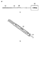
図1において、(a)は第1の実施形態に係る圧力測定装置の概略構成を示す平面図、(b)は(a)の感圧センサモジュール部分を拡大して示す斜視図である。図1において、圧力測定装置は、ガイドワイヤ100の先端から所定の位置に感圧センサモジュール200を装着し、感圧センサモジュール200から引き出されるリードワイヤを計測演算装置300に接続する。そして、当該計測演算装置300にて、感圧センサモジュール200の歪検出出力からセンサ設置点における圧力を算出する。ガイドワイヤ100には、コイル800(Pt、Au)が巻装され、その上に親水性コーティングが施されている。
1A is a plan view showing a schematic configuration of the pressure measuring device according to the first embodiment, and FIG. 1B is an enlarged perspective view showing a pressure-sensitive sensor module portion of FIG. In FIG. 1, the pressure measurement device attaches a pressure-
図2は図1に示す感圧センサモジュール200の構造を示す分解斜視図である。図2において、210はガイドワイヤ100が挿通され、その先端から所定の位置に固定されるフレームである。このフレーム210は中空パイプ状であり、その周面に第1の歪センサ220と第2の歪センサ230がそれぞれ平行に対向配置される。
FIG. 2 is an exploded perspective view showing the structure of the pressure-
図3は上記第1及び第2の歪センサ220、230の具体的な構成を示す平面図である。尚、第2の歪センサ230は第1の歪センサ220と同様の構成であるので、ここでは第1の歪センサ220を用いてその構成を説明する。尚、かっこ内の符号は第2の歪センサ230の符号を示している。
FIG. 3 is a plan view showing a specific configuration of the first and
図3に示す第1の歪センサ220(230)において、基板221(231)は、例えば矩形状であり、例えばセラミック基板、又は絶縁膜が塗布された金属基板、或いはガラス基板により構成される。基板221(231)は、その幅方向に剛性を有し、厚み方向に変位可能である必要がある。 In the first strain sensor 220 (230) shown in FIG. 3, the substrate 221 (231) has, for example, a rectangular shape, and is made of, for example, a ceramic substrate, a metal substrate coated with an insulating film, or a glass substrate. The substrate 221 (231) needs to be rigid in the width direction and displaceable in the thickness direction.
セラミック基板としては、例えばジルコニア、酸化アルミニウム、窒化アルミニウムが適用可能である。セラミック基板は、基板そのものが絶縁性を有しており、特に、ジルコニアは、脆性破壊に対して強い材料である。よって、本実施形態では、基板221(230)としてジルコニアの使用が望ましい。 As the ceramic substrate, for example, zirconia, aluminum oxide, or aluminum nitride is applicable. The ceramic substrate itself has an insulating property, and in particular, zirconia is a material strong against brittle fracture. Therefore, in this embodiment, it is desirable to use zirconia as the substrate 221 (230).
絶縁膜が塗布された金属基板としては、例えば鉄、又は、ステンレススチールが適用可能である。絶縁膜としては、例えばケイ酸ガラス、酸化アルミニウム、窒化アルミニウム、ポリイミドなどが適用可能である。絶縁膜が塗布された金属基板は、基材としての金属基板そのものが脆性破壊に対して強い材料であるという特徴を有している。 As the metal substrate on which the insulating film is applied, for example, iron or stainless steel is applicable. As the insulating film, for example, silicate glass, aluminum oxide, aluminum nitride, polyimide, or the like is applicable. A metal substrate coated with an insulating film has a feature that the metal substrate itself as a base material is a material strong against brittle fracture.
ガラス基板としては、耐熱強化ガラス、例えばパイレックス(登録商標)、テンパックス(登録商標)などが適用可能である。ガラス基板は、基板そのものが絶縁性を有するとともに、安価であるという特徴を有している。 As the glass substrate, heat-resistant tempered glass such as Pyrex (registered trademark), Tempax (registered trademark), or the like is applicable. The glass substrate is characterized in that the substrate itself has insulating properties and is inexpensive.
基板221(231)の一表面において、例えば長手方向ほぼ中央部には、例えば薄膜パターンにより、感歪抵抗膜としての歪ゲージ222(232)が形成されている。 On one surface of the substrate 221 (231), a strain gauge 222 (232) as a strain sensitive resistance film is formed, for example, by a thin film pattern, for example, at a substantially central portion in the longitudinal direction.
この歪ゲージ222(232)は、基板221(231)上に例えば高いゲージ率を有する感歪抵抗膜として機能するもので、金属材料又は半導体材料が、例えばスパッタリング、及びエッチングを用いて形成したものである。歪ゲージ222(232)は、薄膜パターンを基板221(231)の長手方向と直交する方向に複数回折り返すことで、感度の向上を図ったものである。 The strain gauge 222 (232) functions as a strain sensitive resistance film having a high gauge factor, for example, on the substrate 221 (231), and a metal material or a semiconductor material is formed by using, for example, sputtering and etching. It is. The strain gauge 222 (232) is intended to improve sensitivity by diffracting the thin film pattern a plurality of times in a direction orthogonal to the longitudinal direction of the substrate 221 (231).
基板221(231)の両端部には電極パッド223、224(233、234)が配置されており、歪ゲージ222(232)の両端部は、パターン配線によって電極パッド223、224(233、234)に接続されている。これら電極パッド223、224(233、234)には、それぞれリードワイヤ225、226(235、236)の端部が長手方向に沿うようにして、例えば半田付けにより接続される。リードワイヤ225(235)は、リードワイヤ226(236)の引き出し方向と同一方向に引き出され、ガイドワイヤ100を辿って計測演算装置300の信号入力端に接続される。
尚、歪ゲージ222(232)の形成位置は、基板221(231)の中央部に限定されるものではなく、基板221(231)の端部近傍に配置するようにしてもよい。すなわち、基板221(231)の変形により、歪ゲージ222(232)に応力が十分に印加される位置であればよい。 The formation position of the strain gauge 222 (232) is not limited to the central portion of the substrate 221 (231), but may be arranged near the end of the substrate 221 (231). In other words, it may be a position where stress is sufficiently applied to the strain gauge 222 (232) due to the deformation of the substrate 221 (231).
図4は、図2に示すフレーム210の具体的な構成を示すもので、(a)は平面図、(b)は正面図、(c)は側面図である。このフレーム210は、第1の歪センサ220と第2の歪センサ230を長手方向に沿って平行に、表面または裏面が対向した状態で配置されるように収容する第1の基板収容部211と第2の基板収容部212を備える。
FIG. 4 shows a specific configuration of the
上記第1の基板収容部211は、収容された基板221に圧力が加わったとき、基板221が内側にたわむように、基板221の両端部を支持して基板中央部を浮かせた状態にする棚部211a、211bを備える。同様に、上記第2の基板収容部212も棚部212a、212bを備える。
The first
また、フレーム210には、第1の基板収容部211の両端から第1の歪センサ220のリードワイヤ225、226を長手方向に案内するためのガイド溝211c、211dが形成され、第2の基板収容部212の両端から第2の歪センサ230のリードワイヤ235、236を長手方向に案内するためのガイド溝212c、212dが形成される。さらに、フレーム210の一方の端面周囲には、ガイド溝211c、212cにより案内されたリードワイヤ225、235を周面に沿って案内するための段差213が形成され、フレーム210の側面には、フレーム端面の段差213によって案内されたリードワイヤ225、235を他方の他面側に案内するためのガイド溝214、215が形成される。これにより、第1及び第2の基板収容部211、212に収容された第1及び第2の歪センサ220、230のリードワイヤ225、226、235、236をフレーム210の一方端から共に引き出し、ガイドワイヤ100に沿って計測演算装置300に接続することができる。
The
図5は、図1に示す計測演算装置300の構成を示すブロック図である。図5において、計測演算装置300は、第1及び第2のブリッジ回路310、320、A/D(アナログ/デジタル)変換部330、演算部340及び表示部350を備える。
FIG. 5 is a block diagram showing a configuration of the
第1のブリッジ回路310、第2のブリッジ回路320は、それぞれ第1、第2の歪センサ220、230を被測定抵抗として接続し、センサに加えられた歪量に相当する抵抗値の変化を電圧値として検出する。
The
図6は、第1及び第2のブリッジ回路310、320の一例を示すものである。第1及び第2のブリッジ回路310、320は、同一回路であるため、第1のブリッジ回路310についてのみ説明する。
FIG. 6 shows an example of the first and
図6に示す第1のブリッジ回路310は、所謂ホーイトストンブリッジ回路である。ホーイトストンブリッジ回路の動作原理は、周知であるため、説明は省略する。このブリッジ回路310では、電源端子Vと接地間に第1の歪センサ(抵抗値Rg)220と抵抗311が直列接続され、さらに、電源端子Vと接地間に抵抗312、313が直列接続されている。これら抵抗311、312、313は、温度補償された抵抗であり、共に抵抗値が“R”に設定されている。第1の歪センサ220と抵抗311との接続ノードと、抵抗312、313の接続ノードとの電位差から電圧Voutが出力される。第1の歪センサ220に応力が加わると、第1の歪センサ220の抵抗値Rgが変化し、出力電圧Voutが変化する。
The
尚、第2のブリッジ回路320には、図6に示す第1の歪センサ220に代えて、第2の歪センサ230が接続されている。
The
図5において、第1及び第2のブリッジ回路310、320の出力電圧Vx1、Vx2は、アナログ/デジタル(A/D)変換部330によりデジタル化された後、演算部340に供給される。演算部340は、A/D変換部330から供給されるデジタル化された第1及び第2のブリッジ回路310、320の出力電圧に基づき、感圧センサ200に加わる圧力値を演算する。その演算結果は、表示部350に表示される。
In FIG. 5, output voltages Vx1 and Vx2 of the first and
上記演算部340の圧力値の演算について、図7を参照して説明する。
The calculation of the pressure value of the
まず、図7(a)に示すように、第1及び第2の歪センサ220、230の基板221、231の長手方向支点間の長さをL、幅をW、厚さをhとし、歪センサ222、232の位置をLs、基板中央で荷重Pを与える位置をL/2、通常状態での変位をδとする。例として、それぞれL=8.0mm, W=0.4mm, h=0.1mm, Ls=3.0mm, P=0.53N (≒5.4gf), δ=約0.1mm とする。このときの表面歪ε(両端及び中央の3点での曲げ)を計算すると、
ε=−702.7×10⁻⁶
となる。
First, as shown in FIG. 7A, the length between the longitudinal fulcrums of the
ε = −702.7 × 10 −6
It becomes.
今、図7(b)に示すように荷重Pがセンサ中央に圧力として与えられたとき、薄膜ゲージ率をKg、ブリッジ供給電圧をVとし、
Kg≒12、V=5.0V
とすると、各歪センサ220、230に生じる歪検出電圧Voutは、
Vout=(1/4)×Kg×V×ε≒−10.5mV
となる。この場合、各歪センサ220、230の出力電圧は共に同極性であることから、両者を合成することで出力電圧は略2倍となり、より精度良く計測することが可能となる。
Now, as shown in FIG. 7B, when a load P is applied as pressure to the center of the sensor, the thin film gauge factor is Kg, the bridge supply voltage is V,
Kg ≒ 12, V = 5.0V
Then, the strain detection voltage Vout generated in each
Vout = (1/4) × Kg × V × ε ≒ −10.5mV
It becomes. In this case, since the output voltages of the
一方、上記の条件で図7(c)に示すように荷重Pがセンサ端部に曲げ応力として与えられたとき、第1及び第2の歪センサ220、230に生じる歪検出電圧Voutは互いに同一電圧となるが、極性が逆になる。このため、両者を合成することで曲げ応力成分はキャンセルされ、圧力の計測には影響しない。
On the other hand, when the load P is applied as a bending stress to the sensor end as shown in FIG. 7C under the above conditions, the strain detection voltages Vout generated in the first and
以上のように、第1の実施形態に係る感圧センサモジュール200によれば、乳頭括約筋測定用のガイドワイヤ100に装着可能なφ0.035inch(φ0.89mm)に組み込めるサイズとして実現することができる。
As described above, the pressure-
特に、この感圧センサモジュール200を中空パイプ構造として、ガイドワイヤ100の芯線が貫通できる構造としたので、ガイドワイヤ100とは別個に容易に製造することができ、圧力測定用ガイドワイヤの製造・組立を容易にすることができる。
In particular, since the pressure-
さらに、歪センサ220、230を2枚、表面または裏面が対向するようにフレーム210に取り付けるようにしたので、計測演算装置300において、感圧センサモジュール200に作用する曲げ力をキャンセルして乳頭括約筋の締め付け力だけを測定することが可能となり、より高精度な圧力の測定することができる。
Further, since two
(第2の実施形態)
図8及び図9を参照して、本発明の第2の実施形態について説明する。
(Second Embodiment)
A second embodiment of the present invention will be described with reference to FIGS.
図8において、(a)は第2の実施形態に係る圧力測定装置の概略構成を示す斜視図、(b)は(a)の感圧センサモジュール部分を拡大して示す斜視図である。図8に示す圧力測定装置は、挿入案内部700、圧力センサモジュール500、計測演算装置600を備える。計測演算装置600は、第1の実施形態の計測演算装置300と同様なので、ここでは説明を省略する。
8A is a perspective view showing a schematic configuration of a pressure measuring device according to the second embodiment, and FIG. 8B is an enlarged perspective view showing a pressure-sensitive sensor module portion of FIG. The pressure measurement device shown in FIG. 8 includes an
上記計測演算装置600から引き出されるガイドワイヤ401の先端部には、弾性変形結合部501を介して感圧センサモジュール500が取り付けられ、さらに、感圧センサモジュール500の他端部にはもう一つの弾性変形結合部502を介して、弾性変形可能で先端に向かって細くなる形状の先端コアシャフト702が取り付けられ、その先端にはコイル(図示せず)が巻装され、その上に親水コーティングが施されている。コイルは第1の実施形態の図1に示すコイル800と同様である。感圧センサモジュール500から引き出されるリードワイヤ(図示せず)は計測演算装置600に接続される。そして、当該計測演算装置600にて、感圧センサモジュール500の歪検出出力からセンサ設置点における圧力が算出される。
A pressure-
図9(a),(b)はそれぞれ図8に示す感圧センサモジュール500の全体図と構造を示す分解斜視図である。図9において、510は両端がそれぞれ非挿入側ガイドワイヤ401の端部と先端コアシャフト702の端部と弾性変形部材501,502を介して結合されるフレームである。このフレーム510は柱状であり、その周面に第1の歪センサ520と第2の歪センサ530がそれぞれ平行に、表面または裏面が対向するように配置した状態で保持される。
FIGS. 9A and 9B are an overall perspective view and an exploded perspective view showing the structure of the pressure-
尚、歪センサ520、530は、図3に示した第1の実施形態の歪センサ220、230と同様の構成である。よって、ここでは歪センサそのものの説明は省略する。また、リードワイヤについても、第1の実施形態の歪センサ220、230と同様の構成なので、フレーム510における配線経路の形成等についても説明及び図示を省略する。
The
上記フレーム510は、第1の歪センサ520と第2の歪センサ530を長手方向に沿って平行に、表面または裏面が対向して配置されるように収容する第1の基板収容部511と第2の基板収容部(図示せず)を備える。
The
上記第1の基板収容部511は、収容された歪センサ520の基板に圧力が加わったとき、基板が内側にたわむように、基板の両端部を支持して基板の中央部を浮かせた状態にする棚部511a、511bを備える。同様に、上記第2の基板収容部も棚部を備える。
When the pressure is applied to the substrate of the stored
すなわち、上記構成による圧力測定装置では、感圧センサモジュール500を、弾性変形結合部501を介してガイドワイヤ401の先端部近傍に設け、そのモジュール500から弾性変形結合部502を介して、弾性変形可能で先端に向かって細くなる形状の先端コアシャフト702を延設し、その先端に先端チップコイル703を取り付けるようにしたので、乳頭部括約筋等の患部まで感圧センサ部分を容易に挿入することができる。
That is, in the pressure measuring device having the above-described configuration, the pressure-
また、感圧センサモジュール500では、一対の歪センサ520、530がそれぞれの表面あるいは裏面が対向するように略平行状態に保持されているので、第1の実施形態と同様に、計測演算装置600において、感圧センサモジュール500に作用する曲げ力をキャンセルして乳頭括約筋の締め付け力だけを測定することが可能となり、より高精度な圧力の測定することができる。
Further, in the pressure-
本発明は上記各実施形態そのままに限定されるものではなく、実施段階ではその要旨を逸脱しない範囲で構成要素を変形して具体化できる。また、上記各実施形態に開示されている複数の構成要素の適宜な組み合わせにより、種々の発明を形成できる。例えば、実施形態に示される全構成要素から幾つかの構成要素を削除してもよい。さらに、異なる実施形態にわたる構成要素を適宜組み合わせてもよい。 The present invention is not limited to the above-described embodiments as they are, and can be embodied by modifying the components without departing from the scope of the invention in the implementation stage. Moreover, various inventions can be formed by appropriately combining a plurality of constituent elements disclosed in the above embodiments. For example, some components may be deleted from all the components shown in the embodiment. Furthermore, constituent elements over different embodiments may be appropriately combined.
100、401…ガイドワイヤ、200、500…感圧センサモジュール、210、510…フレーム、211、511…第1の基板収容部、212…第2の基板収容部、211a、211b、212a、212b、511a、511b…棚部、211c、211d、212c、212d、214、215…ガイド溝、213…段差、220、520…第1の歪センサ、221…基板、222…歪ゲージ、223、224…電極パッド、225、226…リードワイヤ、230…第2の歪センサ、231…基板、232…歪ゲージ、233、234…電極パッド、235、236…リードワイヤ、300…計測演算装置、310…第1のブリッジ回路、311、312、313…抵抗、320…第2のブリッジ回路、330…A/D(アナログ/デジタル)変換部、340…演算部、350…表示部、700…挿入案内部、702…先端コアシャフト、703…先端チップコイル
DESCRIPTION OF
Claims (8)
周面に、前記一対の歪センサを長手方向に沿って平行にかつ表面または裏面を対向させた状態でそれぞれの両端を保持する一対の収容部を形成してなるフレームと
を具備し、
前記フレームはガイドワイヤの任意の位置に固定される感圧センサモジュール。 A pair of strain sensors each formed by forming a strain gauge on a rectangular substrate;
A frame formed on the peripheral surface with a pair of accommodating portions that hold both ends of the pair of strain sensors in parallel with each other along the longitudinal direction and with the front or back surfaces facing each other;
The frame is a pressure-sensitive sensor module fixed to an arbitrary position of a guide wire.
前記フレームの両端に弾性変形結合部を装備して前記ガイドワイヤと弾性変形自在に結合する請求項1記載の感圧センサモジュール。 The frame is columnar,
The pressure-sensitive sensor module according to claim 1, wherein an elastic deformation coupling portion is provided at both ends of the frame so as to be elastically deformable with the guide wire.
前記フレームの両端に弾性変形結合部を装備して前記ガイドワイヤと弾性変形自在に結合する請求項4記載の圧力測定用ガイドワイヤ。 The frame is columnar,
The pressure measurement guide wire according to claim 4, wherein an elastic deformation coupling portion is provided at both ends of the frame so as to be elastically deformable with the guide wire.
前記一対の歪センサそれぞれの歪ゲージに生じる抵抗分を電圧値に換算し合成することで圧力を計測する計測演算手段と
を具備する圧力測定装置。 A pair of strain sensors each formed by forming a strain gauge on a rectangular substrate is housed in a pair of housing portions formed on the peripheral surface of the frame, and the pair of strain sensors are parallel to the longitudinal direction on the surface. Alternatively, a pressure-measuring guide wire in which a pressure-sensitive sensor module in which both ends are held in a state where the back surfaces face each other is arranged at an arbitrary position of the guide wire, and
A pressure measurement apparatus comprising: a measurement calculation unit that measures a pressure by converting a resistance component generated in a strain gauge of each of the pair of strain sensors into a voltage value and combining them.
それぞれ前記一対の歪センサを被測定抵抗として接続し、各センサに加えられた歪量に相当する抵抗値の変化を電圧値として検出する一対のブリッジ回路と、
前記一対のブリッジ回路の出力電圧をそれぞれの極性に基づいて合成する合成手段と
を備える請求項7記載の圧力測定装置。 The measurement calculation means includes
A pair of bridge circuits that connect the pair of strain sensors as resistances to be measured and detect a change in resistance value corresponding to the amount of strain applied to each sensor as a voltage value;
The pressure measuring apparatus according to claim 7, further comprising a combining unit that combines the output voltages of the pair of bridge circuits based on respective polarities.
Priority Applications (2)
| Application Number | Priority Date | Filing Date | Title |
|---|---|---|---|
| JP2014124293A JP2017156085A (en) | 2014-06-17 | 2014-06-17 | Pressure-sensitive sensor module, guide wire for measuring pressure, and pressure measuring device |
| PCT/JP2015/067488 WO2015194598A1 (en) | 2014-06-17 | 2015-06-17 | Pressure-sensor module, pressure-measurement guide wire, and pressure measurement device |
Applications Claiming Priority (1)
| Application Number | Priority Date | Filing Date | Title |
|---|---|---|---|
| JP2014124293A JP2017156085A (en) | 2014-06-17 | 2014-06-17 | Pressure-sensitive sensor module, guide wire for measuring pressure, and pressure measuring device |
Publications (1)
| Publication Number | Publication Date |
|---|---|
| JP2017156085A true JP2017156085A (en) | 2017-09-07 |
Family
ID=54935578
Family Applications (1)
| Application Number | Title | Priority Date | Filing Date |
|---|---|---|---|
| JP2014124293A Pending JP2017156085A (en) | 2014-06-17 | 2014-06-17 | Pressure-sensitive sensor module, guide wire for measuring pressure, and pressure measuring device |
Country Status (2)
| Country | Link |
|---|---|
| JP (1) | JP2017156085A (en) |
| WO (1) | WO2015194598A1 (en) |
Families Citing this family (2)
| Publication number | Priority date | Publication date | Assignee | Title |
|---|---|---|---|---|
| CN106943137B (en) * | 2017-05-02 | 2023-09-15 | 温州市中心医院 | Intelligent biliary tract pressure measuring device |
| JP6738509B2 (en) * | 2018-07-13 | 2020-08-12 | Semitec株式会社 | System with sensor device, catheter and sensor device |
Family Cites Families (5)
| Publication number | Priority date | Publication date | Assignee | Title |
|---|---|---|---|---|
| FR2543834B1 (en) * | 1983-04-07 | 1985-08-23 | Descartes Universite Rene | VARIABLE GEOMETRY PROBE FOR MEASURING RADIAL CONSTRAINTS IN A SPHINCTER OF A LIVING ORGANISM |
| US4850358A (en) * | 1986-11-14 | 1989-07-25 | Millar Instruments, Inc. | Method and assembly for introducing multiple devices into a biological vessel |
| JPH04141139A (en) * | 1990-10-03 | 1992-05-14 | Aisin Seiki Co Ltd | Catheter |
| JP2007503286A (en) * | 2003-05-13 | 2007-02-22 | サバコア インコーポレイテッド | System and method for detecting, diagnosing and treating cardiovascular disease |
| GB0519259D0 (en) * | 2005-09-21 | 2005-10-26 | Imp College Innovations Ltd | A device |
-
2014
- 2014-06-17 JP JP2014124293A patent/JP2017156085A/en active Pending
-
2015
- 2015-06-17 WO PCT/JP2015/067488 patent/WO2015194598A1/en active Application Filing
Also Published As
| Publication number | Publication date |
|---|---|
| WO2015194598A1 (en) | 2015-12-23 |
Similar Documents
| Publication | Publication Date | Title |
|---|---|---|
| JP5054103B2 (en) | Force sensor for detecting force vector | |
| CN108778181B (en) | Instrument force sensor using strain gauges in a faraday cage | |
| WO2015194597A1 (en) | Pressure sensor and pressure-sensitive catheter | |
| DK1240868T3 (en) | Apparatus for measuring a plurality of electrical signals from a patient's body | |
| EP2658438A2 (en) | Lumen based pressure sensing guidewire system with distortion correction | |
| US20160310080A1 (en) | Polymer-based cardiovascular biosensors, manufacture, and uses thereof | |
| JP2017156085A (en) | Pressure-sensitive sensor module, guide wire for measuring pressure, and pressure measuring device | |
| JP6466678B2 (en) | Semiconductor integrated circuit, variable gain amplifier, and sensor system | |
| US8640552B2 (en) | MEMS airflow sensor die incorporating additional circuitry on the die | |
| Maundy et al. | Strain gauge amplifier circuits | |
| Melvås et al. | A free-hanging strain-gauge for ultraminiaturized pressure sensors | |
| JP6290250B2 (en) | Pressure sensing endovascular device, system, and method | |
| EP3749175A1 (en) | Arrangement with catheter and sensor arrangement | |
| KR101074599B1 (en) | Temperature Detector and Measurement Method Of The Same | |
| JP4209429B2 (en) | Strain / temperature measurement method | |
| JP7430575B2 (en) | Voltage zeroing pressure sensor preamplifier | |
| Maeda et al. | Micro-Machineed Catheter Sensor Systematization for In-Situ Breathing and Optical Imaging Measurements in Bronchus Region in Lung System | |
| Sousa et al. | A thin-film aluminum strain gauges array in a flexible gastrointestinal catheter for pressure measurements | |
| TW200803789A (en) | Pulse measuring device | |
| JP3546203B2 (en) | Strain gauge | |
| Hsu et al. | Development of A MEMS Based Manometric Catheter for Diagnosis of Functional Swallowing Disorders. | |
| Silva et al. | Flexible gastrointestinal motility pressure sensors based on aluminum thin-film strain-gauge arrays | |
| JP6738509B2 (en) | System with sensor device, catheter and sensor device | |
| Pelgrims et al. | Sensor and instrumentation for cable tension quantification | |
| Dong¹ et al. | Check for updates |