JP2017155779A - Controller of vehicular automatic transmission - Google Patents
Controller of vehicular automatic transmission Download PDFInfo
- Publication number
- JP2017155779A JP2017155779A JP2016037728A JP2016037728A JP2017155779A JP 2017155779 A JP2017155779 A JP 2017155779A JP 2016037728 A JP2016037728 A JP 2016037728A JP 2016037728 A JP2016037728 A JP 2016037728A JP 2017155779 A JP2017155779 A JP 2017155779A
- Authority
- JP
- Japan
- Prior art keywords
- input shaft
- rotational speed
- automatic transmission
- abnormal
- vehicle
- Prior art date
- Legal status (The legal status is an assumption and is not a legal conclusion. Google has not performed a legal analysis and makes no representation as to the accuracy of the status listed.)
- Pending
Links
Images


Abstract
Description
本発明は、油圧式摩擦係合装置が係合されることで複数のギヤ段が選択的に形成される車両用自動変速機の制御装置に関するものである。 The present invention relates to a control device for an automatic transmission for a vehicle in which a plurality of gear stages are selectively formed by engaging a hydraulic friction engagement device.
複数のソレノイドバルブから係合油圧がそれぞれ供給される複数の油圧式摩擦係合装置を有する車両用自動変速機において、複数のソレノイドバルブのうちの所定数のソレノイドバルブを制御して所定の変速段が選択的に成立させられる車両用自動変速機の制御装置が知られている。たとえば、特許文献1に記載された車両用自動変速機の制御装置がそれである。 In a vehicular automatic transmission having a plurality of hydraulic friction engagement devices to which engagement hydraulic pressures are respectively supplied from a plurality of solenoid valves, a predetermined gear stage is controlled by controlling a predetermined number of solenoid valves among the plurality of solenoid valves. There is known a control device for an automatic transmission for a vehicle in which is established selectively. For example, this is the control device for an automatic transmission for a vehicle described in Patent Document 1.
上記特許文献1の技術では、複数のソレノイドバルブのうちの故障したソレノイドバルブを検出する故障検出部を車両用自動変速機の制御装置に備え、故障したソレノイドバルブが検出された場合には、そのソレノイドバルブ以外のソレノイドバルブで形成される変速段へ変速させる。その際、急減速を発生させる可能性がある場合には、車速が所定値に低下するまで車両用自動変速機を中立状態(ニュートラル状態)としている。しかしながら、上記特許文献1では、故障検出部でソレノイドバルブの故障が検出された後に車両用自動変速機を変速させているため、ソレノイドバルブの故障によって車両用自動変速機の入力軸回転数および出力軸回転数に回転数差が生じて、入力軸回転数が同期回転数よりも高くなる過高回転状態または入力軸回転数が同期回転数よりも低くなる過低回転状態が、車両用自動変速機の内部構成部品、たとえばピニオンなどの内部メンバの過回転を生じさせる場合には、内部メンバの過回転が入力軸回転数の上昇に起因する場合は燃料供給を停止するエンジンフューエルカットを実行することで入力軸回転数を正常な回転数まで抑えることで、内部メンバの過回転を回避できる。しかし、内部メンバの過回転が入力軸回転数の下降に起因する場合はエンジンフューエルカットを実行しても過回転を回避することはできなかった。そのような内部メンバの過回転は、自動変速機の耐久性に影響する可能性がある。 In the technique of the above-mentioned Patent Document 1, a failure detection unit that detects a broken solenoid valve among a plurality of solenoid valves is provided in a control device for an automatic transmission for a vehicle, and when a broken solenoid valve is detected, Shifting to a gear stage formed by a solenoid valve other than the solenoid valve. At this time, if there is a possibility of sudden deceleration, the vehicle automatic transmission is kept in a neutral state (neutral state) until the vehicle speed drops to a predetermined value. However, in Patent Document 1, since the vehicle automatic transmission is shifted after the failure detection unit detects the failure of the solenoid valve, the input shaft rotational speed and output of the vehicle automatic transmission due to the failure of the solenoid valve. An automatic speed change for a vehicle is caused by an excessively high speed state in which the rotational speed difference occurs in the shaft rotational speed and the input shaft rotational speed is higher than the synchronous rotational speed or an excessively low rotational speed in which the input shaft rotational speed is lower than the synchronous rotational speed. When an internal member of the machine, for example, an internal member such as a pinion is over-rotated, if the internal member over-rotation is caused by an increase in the input shaft rotational speed, an engine fuel cut is performed to stop fuel supply. By suppressing the input shaft rotational speed to a normal rotational speed, it is possible to avoid over-rotation of the internal member. However, when the overspeed of the internal member is caused by the decrease of the input shaft speed, the overspeed cannot be avoided even if the engine fuel cut is executed. Such over-rotation of the internal member can affect the durability of the automatic transmission.
本発明は、以上の事情を背景として為されたものであり、その目的とするところは、車両用自動変速機のソレノイドバルブが故障した場合に、車両用自動変速機の内部メンバの過回転状態を抑制する車両用自動変速機の制御装置を提供することにある。 The present invention has been made against the background of the above circumstances, and the object of the present invention is to provide an over-rotation state of an internal member of a vehicle automatic transmission when a solenoid valve of the vehicle automatic transmission fails. It is providing the control apparatus of the automatic transmission for vehicles which suppresses.
本発明の要旨とするところは、(a)複数のソレノイドバルブから係合油圧がそれぞれ供給される複数の油圧式摩擦係合装置を有する車両用自動変速機において、前記複数のソレノイドバルブのうちの所定数のソレノイドバルブを制御して所定の変速段が選択的に成立させられる車両用自動変速機の制御装置であって、(b)前記車両用自動変速機の入力軸回転数を算出する入力軸回転数算出部と、(c)前記車両用自動変速機の出力軸回転数を算出する出力軸回転数算出部と、(d)前記所定の変速段に対応する変速比が得られる場合の入力軸回転数よりも低回転数側に予め設定された入力軸異常回転数閾値を前記出力軸回転数に基づいて設定する入力軸異常回転数設定部と、(e)前記入力軸回転数算出部で算出された前記入力軸回転数が、前記入力軸異常回転数未満であるか否かを判定する異常判定部と、(f)前記異常判定部で前記入力軸回転数が前記入力軸異常回転数未満であったと判定された場合には、そのときの変速段を成立させている複数の油圧式摩擦係合装置を全て非係合とする異常時制御部と、を備えることにある。 The gist of the present invention is that: (a) in an automatic transmission for a vehicle having a plurality of hydraulic friction engagement devices to which engagement hydraulic pressures are respectively supplied from a plurality of solenoid valves, A control device for an automatic transmission for a vehicle that controls a predetermined number of solenoid valves to selectively establish a predetermined shift speed, and (b) an input for calculating an input shaft rotational speed of the automatic transmission for the vehicle A shaft rotation number calculation unit, (c) an output shaft rotation number calculation unit for calculating an output shaft rotation number of the vehicle automatic transmission, and (d) a gear ratio corresponding to the predetermined gear stage is obtained. An input shaft abnormal rotational speed setting unit for setting an input shaft abnormal rotational speed threshold value set in advance on the lower rotational speed side than the input shaft rotational speed based on the output shaft rotational speed; and (e) calculating the input shaft rotational speed. The input shaft rotation speed calculated by the unit An abnormality determination unit that determines whether or not the input shaft is below the abnormal rotational speed; and (f) when the abnormality determination unit determines that the input shaft rotational speed is less than the input shaft abnormal rotational speed. Is provided with an abnormal-time control unit that disengages all of the plurality of hydraulic friction engagement devices that establish the gear position at that time.
このようにすれば、前記入力軸回転数が、前記所定の変速段に対応する変速比が得られる場合の正常な入力軸回転数よりも低回転数側に設定された前記入力軸異常回転数閾値未満となると前記異常判定部で判定された場合には、そのときの変速段を成立させている油圧式摩擦係合装置の全てが非係合とされることにより前記車両用自動変速機をニュートラル状態とされるので、前記車両用自動変速機の内部メンバの過回転が抑制することができる。 In this case, the input shaft rotational speed is set to a lower rotational speed side than the normal input shaft rotational speed when the gear ratio corresponding to the predetermined shift speed is obtained. When the abnormality determination unit determines that the vehicle speed is less than the threshold value, all of the hydraulic friction engagement devices that establish the gear position at that time are disengaged, and thus the vehicle automatic transmission is Since it is in the neutral state, over-rotation of the internal member of the vehicle automatic transmission can be suppressed.
以下、本発明の一実施例について図面を参照して説明する。なお、以下の実施例において図は適宜簡略化或いは変形されており、各部の寸法比および形状等は必ずしも正確に描かれていない。 An embodiment of the present invention will be described below with reference to the drawings. In the following embodiments, the drawings are appropriately simplified or modified, and the dimensional ratios, shapes, and the like of the respective parts are not necessarily drawn accurately.
図1は、本発明が適用される車両10の概略構成を説明する図であると共に、車両10における制御系統の要部を説明する図である。図1において、車両10は、走行用の駆動力源として機能するガソリンエンジンやディーゼルエンジン等のエンジン12と、駆動輪14と、エンジン12と駆動輪14との間に設けられた動力伝達装置16とを備えている。動力伝達装置16は、車体に取り付けられる非回転部材としてのトランスミッションケース18(以下、ケース18という)内において、エンジン12に連結された流体式伝動装置としての公知のトルクコンバータ20、トルクコンバータ20に連結された車両用自動変速機22(以下、自動変速機22という)、自動変速機22の出力回転部材である出力軸24に連結されたプロペラシャフト26、そのプロペラシャフト26に連結された差動歯車装置(ディファレンシャルギヤ)28、その差動歯車装置28に連結された1対の車軸30等を備えている。このように構成された動力伝達装置16において、エンジン12の動力(或いはトルク)は、トルクコンバータ20、自動変速機22、プロペラシャフト26、差動歯車装置28、及び車軸30等を順次介して1対の駆動輪14へ伝達される。
FIG. 1 is a diagram illustrating a schematic configuration of a
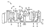
図2は、トルクコンバータ20や自動変速機22を説明する骨子図である。尚、トルクコンバータ20や自動変速機22等は中心線(軸心RC)に対して略対称的に構成されており、図2ではその中心線の下半分が省略されている。又、図2中の軸心RCはエンジン12、トルクコンバータ20の回転軸心である。
FIG. 2 is a skeleton diagram illustrating the
図2において、トルクコンバータ20は、軸心RCと同心に配設されており、エンジン12に連結されたポンプ翼車20p、及び自動変速機22の入力回転部材である変速機入力軸32に連結されたタービン翼車20tを備えている。ポンプ翼車20pには、機械式のオイルポンプ34が連結されている。これにより、機械式のオイルポンプ34はエンジン12により回転駆動されることにより自動変速機22を変速制御したり、動力伝達装置16の動力伝達経路の各部に潤滑油を供給したりする為の作動油圧を発生する。
In FIG. 2, the
自動変速機22は、エンジン12から駆動輪14までの動力伝達経路の一部を構成し、複数の摩擦係合装置の何れかが選択的に係合されることによりギヤ比(変速比)が異なる複数のギヤ段(変速段)が形成される有段式の自動変速機として機能する遊星歯車式多段変速機である。例えば、公知の車両によく用いられる所謂クラッチツゥクラッチ変速を行う有段変速機である。この自動変速機22は、シングルピニオン型の第1遊星歯車装置36と、ラビニヨ型に構成されているシングルピニオン型の第2遊星歯車装置38及びダブルピニオン型の第3遊星歯車装置40と、シングルピニオン型の第4遊星歯車装置42とを同軸線上(軸心RC上)に有し、入力軸32の回転を変速して出力軸24から出力する。
The
第1遊星歯車装置36、第2遊星歯車装置38、第3遊星歯車装置40、及び第4遊星歯車装置42は、良く知られているように、サンギヤ(S1、S2、S3、S4)、ピニオンギヤ(P1、P2、P3、P4)を自転及び公転可能に支持するキャリヤ(CA1、CA2、CA3、CA4)、及びピニオンギヤを介してサンギヤと噛み合うリングギヤ(R1、R2、R3、R4)によって各々3つの回転要素(回転部材)が構成されている。そして、それら各々3つの回転要素は、直接的に或いは摩擦係合装置(クラッチC1,C2,C3,C4、及びブレーキB1,B2)を介して間接的(或いは選択的)に、一部が互いに連結されたり、変速機入力軸32、ケース18、或いは出力軸24に連結されている。
As is well known, the first
上記クラッチC1,C2,C3,C4、及びブレーキB1,B2(以下、特に区別しない場合は、それ等を単にクラッチC、ブレーキB、或いは係合装置という)は、公知の車両用自動変速機においてよく用いられている油圧式の摩擦係合装置であって、油圧アクチュエータにより押圧される湿式多板型のクラッチやブレーキ、油圧アクチュエータによって引き締められるバンドブレーキなどにより構成される。このように構成されたクラッチC及びブレーキBは、自動変速機22に備えられた油圧制御回路50(図1、図4参照)が有するリニアソレノイドバルブSL1−SL6等からの油圧によりそれぞれのトルク容量(すなわち係合力)が変化させられて、係合と解放とが切り替えられる。
The clutches C1, C2, C3, and C4 and the brakes B1 and B2 (hereinafter referred to simply as the clutch C, the brake B, or the engaging device unless otherwise distinguished) are known in a known automatic transmission for vehicles. A hydraulic friction engagement device that is often used, and includes a wet multi-plate clutch and brake pressed by a hydraulic actuator, a band brake tightened by a hydraulic actuator, and the like. The clutch C and the brake B configured in this way have their torque capacities depending on the hydraulic pressure from the linear solenoid valves SL1-SL6 and the like included in the hydraulic control circuit 50 (see FIGS. 1 and 4) provided in the
油圧制御回路50によってクラッチC及びブレーキBの係合と解放とが制御されることで、図3の作動図表に示すように、運転者のアクセル操作や車速V等に応じて前進10段の各ギヤ段が形成される。図3の「1st」−「10th」はそれぞれ前進ギヤ段としての第1速ギヤ段−第10速ギヤ段を意味しており、各ギヤ段に対応する自動変速機22のギヤ比γ(=変速機入力軸回転速度Nin/出力軸回転速度Nout)は、第1遊星歯車装置36、第2遊星歯車装置38、第3遊星歯車装置40、及び第4遊星歯車装置42の各歯車比(=サンギヤの歯数/リングギヤの歯数)によって適宜定められる。「Rev」は後進ギヤ段を意味している。
By controlling the engagement and disengagement of the clutch C and the brake B by the
図3の作動図表は、上記各ギヤ段とリニアソレノイドバルブSL1−SL6に対するソレノイド指示との関係、及び上記各ギヤ段と係合装置の各作動状態との関係をまとめたものである。図3において、「○」はリニアソレノイドバルブSL1−SL6を作動させる(オンする)係合指令信号の出力および係合装置の係合を、空欄は上記係合指令信号の非出力および係合装置の非係合(解放)をそれぞれ表している。このように、自動変速機22は、所定のリニアソレノイドバルブSL1−SL6等の作動による所定の係合装置への係合油圧の供給によってその所定の係合装置が係合されることで複数のギヤ段が択一的(選択的)に形成される自動変速機である。
The operation chart of FIG. 3 summarizes the relationship between the gears and solenoid instructions for the linear solenoid valves SL1 to SL6, and the relationship between the gears and the operating states of the engagement devices. In FIG. 3, “◯” indicates the output of the engagement command signal for operating (turning on) the linear solenoid valves SL1-SL6 and the engagement of the engagement device, and the blank indicates the non-output of the engagement command signal and the engagement device. Represents non-engagement (release). As described above, the
図1に戻り、車両10には、例えば自動変速機22の変速制御などに関連する自動変速機22の制御装置を含む電子制御装置80が備えられている。よって、図1は、電子制御装置80の入出力系統を示す図でもあり、又、電子制御装置80による制御機能の要部を説明する機能ブロック線図である。電子制御装置80は、例えばCPU、RAM、ROM、入出力インターフェース等を備えた所謂マイクロコンピュータを含んで構成されており、CPUはRAMの一時記憶機能を利用しつつ予めROMに記憶されたプログラムに従って信号処理を行うことにより車両10の各種制御を実行する。例えば、電子制御装置80は、エンジン12の出力制御、自動変速機22の変速制御等を実行するようになっており、必要に応じてエンジン出力制御用電子制御装置や油圧制御用電子制御装置等に分けて構成される。
Returning to FIG. 1, the
電子制御装置80には、車両10が備える各種センサ(例えば各種回転速度センサ70,72,74、アクセル開度センサ76、スロットルセンサ78など)による検出信号に基づく各種実際値(例えばエンジン回転速度Ne(rpm)、タービン回転速度Nt(rpm)である変速機入力軸回転速度Nin(rpm)、車速Vに対応する出力軸回転速度Nout(rpm)、アクセル開度θacc(%)、スロットル弁開度θth(%)など)が、それぞれ供給される。又、電子制御装置80からは、エンジン12の出力制御の為のエンジン出力制御指令信号Se、自動変速機22の変速に関する油圧制御の為の油圧制御指令信号Sp等が、それぞれ出力される。油圧制御指令信号Spは、例えば所定の係合装置を係合させる為の係合指令信号であって、クラッチC、ブレーキBの各油圧アクチュエータACT1−ACT6へ供給される各係合油圧Pc1,Pc2,Pc3,Pc4,Pb1,Pb2を調圧する各リニアソレノイドバルブSL1−SL6を作動させる為の係合指令信号であり、油圧制御回路50(すなわち所定のリニアソレノイドバルブSL1−SL6)へ出力される。
The
図4は、クラッチC及びブレーキBの各油圧アクチュエータACT1−ACT6の作動を制御するリニアソレノイドバルブSL1−SL6等に関する油圧制御回路50の要部を示す回路図である。図4において、油圧制御回路50は、油圧供給装置52と、リニアソレノイドバルブSL1−SL6とを備えている。
FIG. 4 is a circuit diagram showing a main part of the
油圧供給装置52は、オイルポンプ34が発生する油圧を元圧としてライン油圧PLを調圧する例えばリリーフ型のプライマリレギュレータバルブ54と、スロットル弁開度θth等で表されるエンジン負荷(例えばエンジントルクTeや変速機入力トルクTat等)に応じてライン油圧PLが調圧される為にプライマリレギュレータバルブ54へ信号圧Psltを供給するリニアソレノイドバルブSLTと、ライン油圧PLを元圧としてモジュレータ油圧PMを一定値に調圧するモジュレータバルブ56と、シフトレバー60の切替操作に連動して機械的或いは電気的に油路が切り替えられるマニュアルバルブ58とを備えている。マニュアルバルブ58は、シフトレバー60が前進走行操作ポジションDにあるときには、入力されたライン油圧PLを前進油圧(Dレンジ圧)PDとして出力し、シフトレバー60が後進走行操作ポジションRにあるときには、入力されたライン油圧PLを後進油圧(Rレンジ圧)PRとして出力する。又、マニュアルバルブ58は、シフトレバー60がニュートラル操作ポジションN或いはパーキング操作ポジションPにあるときには、油圧の出力を遮断し、前進油圧PD及び後進油圧PRを排出側へ導く。このように、油圧供給装置52は、ライン油圧PL、モジュレータ油圧PM、前進油圧PD、及び後進油圧PRを出力する。
The hydraulic
クラッチC1,C4,ブレーキB1の各油圧アクチュエータACT1,ACT4,ACT5には、前進油圧PDを元圧としてそれぞれリニアソレノイドバルブSL1,SL4,SL5により調圧された係合油圧Pc1,Pc4,Pb1が供給される。又、クラッチC2,C3,B2の各油圧アクチュエータACT2,ACT3,ACT6には、ライン油圧PLを元圧としてそれぞれリニアソレノイドバルブSL2,SL3,SL6により調圧された係合油圧Pc2,Pc3,Pb2が供給される。リニアソレノイドバルブSL1−SL6は、基本的には何れも同じ構成であり、電子制御装置80によりそれぞれ独立に励磁、非励磁や電流制御が為される。
The hydraulic actuators ACT1, ACT4, and ACT5 of the clutches C1, C4, and the brake B1 are supplied with engagement hydraulic pressures Pc1, Pc4, and Pb1 that are regulated by the linear solenoid valves SL1, SL4, and SL5, respectively, using the forward hydraulic pressure PD as a source pressure. Is done. Further, the hydraulic actuators ACT2, ACT3, ACT6 of the clutches C2, C3, B2 have engagement hydraulic pressures Pc2, Pc3, Pb2 regulated by the linear solenoid valves SL2, SL3, SL6, respectively, using the line hydraulic pressure PL as a source pressure. Supplied. The linear solenoid valves SL1 to SL6 basically have the same configuration, and are individually excited, de-energized, and controlled by the
図1に戻り、電子制御装置80は、入力軸回転数算出手段すなわち入力軸回転数算出部82、出力軸回転数算出手段すなわち出力軸回転数算出部84、入力軸異常回転数閾値設定手段すなわち入力軸異常回転数閾値設定部86、異常判定手段すなわち異常判定部88、異常時制御手段すなわち異常時制御部90、および変速制御手段すなわち変速制御部92を機能的に備えている。
Returning to FIG. 1, the
変速制御部92は、通常(正常時)は車速V及びアクセル開度Accを変数として予め定められた関係(変速マップ、変速線図)に実際の車速V及びアクセル開度Accを適用することで変速判断を行い、その判断した所定の前進ギヤ段が得られるように自動変速機22の変速に関与する係合装置を係合させる変速指令として油圧制御指令信号Sp(係合指令信号)を油圧制御回路50へ出力する。この油圧制御指令信号Spに従って、自動変速機22の変速が実行されるように油圧制御回路50内のリニアソレノイドバルブSL1−SL6が駆動(作動)させられて、その変速に関与する係合装置の油圧アクチュエータACT1−ACT6が作動させられる。
The
入力軸回転数算出部82は、車両10が備える入力軸回転速度センサ72から出力されるパルス信号に基づき、所定の変速段での入力軸32の入力軸回転数Nin(rpm)を算出する。出力軸回転数算出部84は、車両10が備える出力軸回転速度センサ74から出力されるパルス信号に基づき、所定の変速段での出力軸24の出力軸回転数Nout(rpm)を算出する。
The input shaft rotational
入力軸異常回転数閾値設定部86は、入力軸異常回転数閾値NAを、現車速に対応する変速比が得られる場合の同期回転数つまり正常時の入力軸回転数Nin0よりも、所定値たとえば同期回転数の10%または1000rpm程度低回転数側に予め設定する。たとえば、変速段「1st」では、SL1が故障した場合の図示しない異常回転閾値マップA1、SL2が故障した場合の図示しない異常回転閾値マップA2、およびSL6が故障した場合の図示しない異常回転閾値マップA6を利用する。それぞれの異常回転閾値マップには、入力軸回転数Ninと出力軸回転数Noutとの関係において異常状態を示す領域が設定されており、変速段「1st」で異常が生じた場合には、異常回転閾値マップA1、A2およびA6を足し合わせていずれかのマップで異常状態と判定される閾値を異常判定閾値とする。そして、入力軸回転数Ninが正常時の入力軸回転数Nin0よりも低回転数側である場合の異常判定閾値を入力軸異常回転数閾値NAとして設定する。
The input shaft abnormal rotation speed threshold
図5は、所定の変速段における入力軸回転数Ninと出力軸回転数Noutとの関係を示す概略図である。図5の縦軸は入力軸回転数Ninを示し、横軸は出力軸回転数Noutを示している。図5で示されるギヤ段同期回転数は、入力軸回転数Ninと出力軸回転数Noutとの比(Nin/Nout)が上記所定の変速段の変速比と一致する場合、つまり正常時の入力軸回転数Nin0と出力軸回転数Nout0との関係を表している。図5の斜線で示される2箇所の領域は、所定の変速段で自動変速機22内のピニオンなどの内部メンバがその許容域を超える過回転状態と判定される内部メンバ過回転領域を示している。ここで、入力軸異常回転数閾値NAは、ギヤ段同期回転数より低い側の内部メンバ過回転領域と車両用自動変速機22の内部メンバに異常が発生しない領域との境界で表される。
FIG. 5 is a schematic diagram showing the relationship between the input shaft rotational speed Nin and the output shaft rotational speed Nout at a predetermined gear position. The vertical axis in FIG. 5 represents the input shaft rotational speed Nin, and the horizontal axis represents the output shaft rotational speed Nout. The gear speed synchronous speed shown in FIG. 5 is obtained when the ratio (Nin / Nout) between the input shaft speed Nin and the output shaft speed Nout matches the speed ratio of the predetermined speed, that is, the normal input. The relationship between the shaft rotational speed Nin0 and the output shaft rotational speed Nout0 is shown. The two regions indicated by hatching in FIG. 5 indicate internal member over-rotation regions where internal members such as pinions in the
入力軸異常回転数閾値NAが算出されると、入力軸異常回転数閾値設定部86は、その入力軸異常回転数閾値NAに基づき、出力軸回転数算出部84で算出された出力軸回転数Noutから実際の車速および変速段で入力軸回転数の異常を判定するための入力軸異常回転数NAdを算出する。
When the input shaft abnormal rotational speed threshold NA is calculated, the input shaft abnormal rotational speed
異常判定部88は、入力軸回転数算出部82で算出された入力軸回転数Ninが入力軸異常回転数閾値設定部86で算出された入力軸異常回転数NAd未満であるか否かを判定する。つまり、異常判定部88は、入力軸回転数Ninが入力軸異常回転数NAd未満となって車両自動変速機22内の内部メンバが過回転している異常状態であるか否かを判定している。
The
異常時制御部90は、入力軸回転数Ninが入力軸異常回転数NAd未満であったと異常判定部88で判定された場合に、そのときの変速段を成立させている複数の油圧式摩擦係合装置を非係合とするために、それらに係合油圧を供給する複数のリニアソレノイドバルブ全てに対して、油圧式摩擦係合装置への係合油圧の供給を停止させる制御を行う。ここで、油圧式摩擦係合装置へ係合油圧を供給するリニアソレノイドバルブSL1−SL6のいずれかに故障が生じると、その故障したリニアソレノイドバルブから係合油圧が油圧式摩擦係合装置へ供給されなくなるため車両用自動変速機22が正常な係合状態ではない異常な係合状態となる。たとえば、図5に示すように、リニアソレノイドバルブの故障によって車両用自動変速機22の入力軸回転数Ninが入力軸異常回転数閾値NA未満となると車両用自動変速機22内のピニオンなどの内部メンバは過回転状態となる。この状態を回避するために、異常時制御部90は、そのときの変速段を成立させている複数の油圧式摩擦係合装置に係合油圧を供給する複数のリニアソレノイドバルブ全てを解放させるOFF指示を実行して油圧式摩擦係合装置への係合油圧の供給を停止させて車両用自動変速機22をニュートラル状態にする。車両用自動変速機22をニュートラル状態にすることにより、車両用自動変速機22内の内部メンバの過回転状態が回避されたら、異常時制御部90はリニアソレノイドバルブへのOFF指示の実行を中止する。
When the
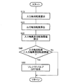
図6は、電子制御装置80の制御作動の要部、すなわち車両用自動変速機22の内部メンバが過回転状態となった場合に、過回転状態を抑制するための制御動作を説明するフローチャートであり、繰り返し実行される。
FIG. 6 is a flowchart for explaining a control operation for suppressing the overspeed state when the main part of the control operation of the
入力軸回転数算出部82に対応するステップ(以下、ステップを省略する)S10では、車両10が備える入力軸回転速度センサ72からのパルス信号に基づき、入力軸32の入力軸回転数Ninが算出される。続いて、出力軸回転数算出部84に対応するS20では、車両10が備える出力軸回転速度センサ74からのパルス信号に基づき、出力軸24の出力軸回転数Noutが算出される。
In a step (hereinafter, step is omitted) S10 corresponding to the input shaft rotational
次に、入力軸異常回転数閾値設定部86に対応するS30では、実際のギヤ段の変速比に対応する正常時の入力軸回転数Nin0、すなわちギヤ段同期回転数よりも、たとえば1000rpm程度低回転数側の値のうち現車両、すなわち出力軸回転数Noutに対応する値に設定された入力軸異常回転数閾値NAが設定される。その入力軸異常回転数閾値NAに基づき、出力軸回転数算出部84で算出された出力軸回転数Noutから異常状態となる入力軸異常回転数NAdが算出される。
Next, in S30 corresponding to the input shaft abnormal rotation speed threshold
次に、異常判定部88に対応するS40では、S10で算出された入力軸回転数Ninが、S30で算出された入力軸異常回転数NAd未満であるか否かが判定される。入力軸回転数Ninが、入力軸異常回転数NAd未満ではない場合は、本ルーチンは終了させられる。しかし、入力軸回転数Ninが入力軸異常回転数NAd未満である場合は、S50が実行される。
Next, in S40 corresponding to the
異常時制御部90に対応するS50では、入力軸回転数Ninが入力軸異常回転数NAd未満であるときの変速段を成立させる複数の油圧式摩擦係合装置に係合油圧を供給する複数のリニアソレノイドバルブ全てに対して、油圧式摩擦係合装置への係合油圧の供給を停止させる制御が行われる。具体的には、入力軸回転数Ninが入力軸異常回転数NAd未満であると判定、つまり車両用自動変速機22内の内部メンバが過回転状態と判定された場合には、異常時制御部90がそのときの変速段を成立させている複数の油圧式摩擦係合装置に係合油圧を供給する複数のリニアソレノイドバルブ全てを解放させるOFF指示を実行することで車両用自動変速機22がニュートラル状態とされる。そして、車両用自動変速機22内の内部メンバの過回転状態が回避されるとリニアソレノイドバルブへのOFF指示が中止される。その後、本ルーチンは終了させられる。
In S50 corresponding to the abnormal
このように、本実施例によれば、入力軸回転数Ninが、所定の変速段に対応する変速比が得られる場合の正常な入力軸回転数Nin0すなわち同期回転数よりも低回転数側に設定された入力軸異常回転数閾値NAd未満となると異常判定部88で判定された場合には、そのときの変速段を成立させている油圧式摩擦係合装置に係合油圧を供給する複数のリニアソレノイドバルブ全てからの係合油圧の供給を異常時制御部90で停止させることにより、車両用自動変速機22をニュートラル状態にすることで車両用自動変速機22内の内部メンバの過回転状態を抑制し、車両用自動変速機22の耐久性を確保する。
Thus, according to the present embodiment, the input shaft rotational speed Nin is on the lower rotational speed side than the normal input shaft rotational speed Nin0, that is, the synchronous rotational speed when the gear ratio corresponding to the predetermined gear stage is obtained. When the
以上、本発明の実施例を図面に基づいて説明したが、本発明はその他の様態にも適用される。 As mentioned above, although the Example of this invention was described based on drawing, this invention is applied also to another aspect.
たとえば、前述の実施例では、異常時制御部90で入力軸回転数Ninが入力軸異常回転数NAd未満であるときの変速段を成立させている複数の油圧式摩擦係合装置に係合油圧を供給する複数のリニアソレノイドバルブ全てを解放させるOFF指示を行っているが、必ずしもこれに限らず、油圧制御回路50が有するリニアソレノイドバルブSL1−SL6全てを解放させるOFF指示を行ってもよい。
For example, in the above-described embodiment, the engagement hydraulic pressure is applied to the plurality of hydraulic friction engagement devices that establish the shift stage when the input shaft rotational speed Nin is less than the input shaft abnormal rotational speed NAd in the
なお、上述したのはあくまでも一実施形態であり、その他一々例示はしないが、本発明は、その趣旨を逸脱しない範囲で当業者の知識に基づいて種々変更、改良を加えた態様で実施することができる。 It should be noted that the above description is merely an embodiment, and other examples are not illustrated. However, the present invention is implemented in variously modified and improved modes based on the knowledge of those skilled in the art without departing from the spirit of the present invention. Can do.
10:車両
22:車両用自動変速機
82:入力軸回転数算出部
84:出力軸回転数算出部
86:入力軸異常回転数閾値設定部
88:異常判定部
90:異常時制御部
Nin:入力軸回転数
Nout:出力軸回転数
NA:入力軸異常回転数閾値
NAd:入力軸異常回転数
10: Vehicle 22: Vehicle automatic transmission 82: Input shaft rotational speed calculation unit 84: Output shaft rotational speed calculation unit 86: Input shaft abnormal rotational speed threshold value setting unit 88: Abnormality determination unit 90: Control unit during abnormality Nin: Input Shaft rotational speed Nout: Output shaft rotational speed NA: Input shaft abnormal rotational speed threshold NAd: Input shaft abnormal rotational speed
Claims (1)
前記車両用自動変速機の入力軸回転数を算出する入力軸回転数算出部と、
前記車両用自動変速機の出力軸回転数を算出する出力軸回転数算出部と、
前記所定の変速段に対応する変速比が得られる場合の入力軸回転数よりも低回転数側に予め設定された入力軸異常回転数閾値を前記出力軸回転数に基づいて設定する入力軸異常回転数設定部と、
前記入力軸回転数算出部で算出された前記入力軸回転数が、前記入力軸異常回転数未満であるか否かを判定する異常判定部と、
前記異常判定部で前記入力軸回転数が前記入力軸異常回転数未満であったと判定された場合には、そのときの変速段を成立させている複数の油圧式摩擦係合装置を全て非係合とする異常時制御部と、
を備えることを特徴とする車両用自動変速機の制御装置。
In a vehicular automatic transmission having a plurality of hydraulic friction engagement devices to which engagement hydraulic pressures are respectively supplied from a plurality of solenoid valves, a predetermined number of solenoid valves among the plurality of solenoid valves are controlled to achieve a predetermined speed change. A control device for an automatic transmission for a vehicle in which a stage is selectively established,
An input shaft rotational speed calculation unit for calculating an input shaft rotational speed of the vehicle automatic transmission;
An output shaft rotational speed calculation unit for calculating the output shaft rotational speed of the vehicle automatic transmission;
An input shaft abnormality in which an input shaft abnormal rotation speed threshold value set in advance on the lower rotation speed side than the input shaft rotation speed when a gear ratio corresponding to the predetermined gear stage is obtained is set based on the output shaft rotation speed. A rotation speed setting section;
An abnormality determination unit that determines whether or not the input shaft rotation number calculated by the input shaft rotation number calculation unit is less than the input shaft abnormal rotation number;
When the abnormality determining unit determines that the input shaft rotational speed is less than the input shaft abnormal rotational speed, all of the plurality of hydraulic friction engagement devices that establish the gear stage at that time are disengaged. An abnormal time control unit,
A control device for an automatic transmission for a vehicle, comprising:
Priority Applications (1)
| Application Number | Priority Date | Filing Date | Title |
|---|---|---|---|
| JP2016037728A JP2017155779A (en) | 2016-02-29 | 2016-02-29 | Controller of vehicular automatic transmission |
Applications Claiming Priority (1)
| Application Number | Priority Date | Filing Date | Title |
|---|---|---|---|
| JP2016037728A JP2017155779A (en) | 2016-02-29 | 2016-02-29 | Controller of vehicular automatic transmission |
Publications (1)
| Publication Number | Publication Date |
|---|---|
| JP2017155779A true JP2017155779A (en) | 2017-09-07 |
Family
ID=59809372
Family Applications (1)
| Application Number | Title | Priority Date | Filing Date |
|---|---|---|---|
| JP2016037728A Pending JP2017155779A (en) | 2016-02-29 | 2016-02-29 | Controller of vehicular automatic transmission |
Country Status (1)
| Country | Link |
|---|---|
| JP (1) | JP2017155779A (en) |
Cited By (5)
| Publication number | Priority date | Publication date | Assignee | Title |
|---|---|---|---|---|
| JP2018135936A (en) * | 2017-02-21 | 2018-08-30 | クノールブレムゼ商用車システムジャパン株式会社 | Transmission controller, control method and program |
| EP3486102A1 (en) | 2017-11-20 | 2019-05-22 | Toyota Jidosha Kabushiki Kaisha | Control system for hybrid vehicle |
| DE102018220838A1 (en) | 2017-12-05 | 2019-06-06 | Toyota Jidosha Kabushiki Kaisha | SWITCHING CONTROL SYSTEM FOR ONE VEHICLE |
| WO2021106785A1 (en) * | 2019-11-29 | 2021-06-03 | ジヤトコ株式会社 | Control device and control method for automatic transmission |
| US11180131B2 (en) | 2017-11-08 | 2021-11-23 | Toyota Jidosha Kabushiki Kaisha | Control system for hybrid vehicle |
Citations (5)
| Publication number | Priority date | Publication date | Assignee | Title |
|---|---|---|---|---|
| JPH01172663A (en) * | 1987-12-28 | 1989-07-07 | Aisin Aw Co Ltd | Fail-safe controller for electronic control type automatic transmission |
| JP2001059570A (en) * | 1999-08-20 | 2001-03-06 | Jatco Transtechnology Ltd | Shift controller at the time of trouble in automatic transmission |
| JP2003254429A (en) * | 2002-03-05 | 2003-09-10 | Aisin Aw Co Ltd | Control system for automatic transmission |
| JP2007162846A (en) * | 2005-12-14 | 2007-06-28 | Toyota Motor Corp | Abnormality determination device of automatic transmission |
| WO2011145393A1 (en) * | 2010-05-17 | 2011-11-24 | アイシン・エィ・ダブリュ株式会社 | Automatic transmission controller |
-
2016
- 2016-02-29 JP JP2016037728A patent/JP2017155779A/en active Pending
Patent Citations (5)
| Publication number | Priority date | Publication date | Assignee | Title |
|---|---|---|---|---|
| JPH01172663A (en) * | 1987-12-28 | 1989-07-07 | Aisin Aw Co Ltd | Fail-safe controller for electronic control type automatic transmission |
| JP2001059570A (en) * | 1999-08-20 | 2001-03-06 | Jatco Transtechnology Ltd | Shift controller at the time of trouble in automatic transmission |
| JP2003254429A (en) * | 2002-03-05 | 2003-09-10 | Aisin Aw Co Ltd | Control system for automatic transmission |
| JP2007162846A (en) * | 2005-12-14 | 2007-06-28 | Toyota Motor Corp | Abnormality determination device of automatic transmission |
| WO2011145393A1 (en) * | 2010-05-17 | 2011-11-24 | アイシン・エィ・ダブリュ株式会社 | Automatic transmission controller |
Cited By (9)
| Publication number | Priority date | Publication date | Assignee | Title |
|---|---|---|---|---|
| JP2018135936A (en) * | 2017-02-21 | 2018-08-30 | クノールブレムゼ商用車システムジャパン株式会社 | Transmission controller, control method and program |
| US11180131B2 (en) | 2017-11-08 | 2021-11-23 | Toyota Jidosha Kabushiki Kaisha | Control system for hybrid vehicle |
| EP3486102A1 (en) | 2017-11-20 | 2019-05-22 | Toyota Jidosha Kabushiki Kaisha | Control system for hybrid vehicle |
| RU2705867C1 (en) * | 2017-11-20 | 2019-11-12 | Тойота Дзидося Кабусики Кайся | Hybrid vehicle drive control system |
| DE102018220838A1 (en) | 2017-12-05 | 2019-06-06 | Toyota Jidosha Kabushiki Kaisha | SWITCHING CONTROL SYSTEM FOR ONE VEHICLE |
| WO2021106785A1 (en) * | 2019-11-29 | 2021-06-03 | ジヤトコ株式会社 | Control device and control method for automatic transmission |
| JPWO2021106785A1 (en) * | 2019-11-29 | 2021-06-03 | ||
| CN114391072A (en) * | 2019-11-29 | 2022-04-22 | 加特可株式会社 | Control device and control method for automatic transmission |
| JP7185790B2 (en) | 2019-11-29 | 2022-12-07 | ジヤトコ株式会社 | AUTOMATIC TRANSMISSION CONTROL DEVICE AND CONTROL METHOD |
Similar Documents
| Publication | Publication Date | Title |
|---|---|---|
| JP4353148B2 (en) | Control device for automatic transmission | |
| JP4158792B2 (en) | Hydraulic control device for automatic transmission for vehicle | |
| JP4887677B2 (en) | Hydraulic control device for automatic transmission for vehicle | |
| JP2017155779A (en) | Controller of vehicular automatic transmission | |
| JP4779938B2 (en) | Hydraulic control device for vehicle | |
| JP5633579B2 (en) | Control device for automatic transmission for vehicle | |
| JP6225884B2 (en) | Vehicle control device | |
| JP6520895B2 (en) | Control device of power transmission device for vehicle | |
| JP6102894B2 (en) | Control device for automatic transmission | |
| US10253877B2 (en) | Vehicle and control method for vehicle | |
| JP4654872B2 (en) | Hydraulic control device for automatic transmission for vehicle | |
| JP2008039114A (en) | Control device for automatic transmission for vehicle | |
| JP6269691B2 (en) | Control device for vehicle power transmission device | |
| JP6520804B2 (en) | Control device of automatic transmission for vehicle | |
| JP6627562B2 (en) | Control device for automatic transmission for vehicles | |
| JP6439661B2 (en) | Control device for stepped automatic transmission for vehicle | |
| WO2012086092A1 (en) | Control device for automatic transmission for vehicle | |
| JP6583187B2 (en) | Vehicle control device | |
| JP2008151190A (en) | Controller of automatic transmission for vehicle | |
| JP2017089691A (en) | Control device of automatic transmission for vehicle | |
| JP6720879B2 (en) | Control device for automatic transmission for vehicle | |
| JP5124944B2 (en) | Control device for automatic transmission | |
| JP2017088010A (en) | Vehicular automatic transmission control device | |
| JP2016114107A (en) | Control device of automatic transmission | |
| JP2017203544A (en) | Hydraulic circuit control device of transmission for vehicle |
Legal Events
| Date | Code | Title | Description |
|---|---|---|---|
| A621 | Written request for application examination |
Free format text: JAPANESE INTERMEDIATE CODE: A621 Effective date: 20180417 |
|
| A977 | Report on retrieval |
Free format text: JAPANESE INTERMEDIATE CODE: A971007 Effective date: 20190222 |
|
| A131 | Notification of reasons for refusal |
Free format text: JAPANESE INTERMEDIATE CODE: A131 Effective date: 20190305 |
|
| A521 | Request for written amendment filed |
Free format text: JAPANESE INTERMEDIATE CODE: A523 Effective date: 20190416 |
|
| A131 | Notification of reasons for refusal |
Free format text: JAPANESE INTERMEDIATE CODE: A131 Effective date: 20191008 |
|
| A02 | Decision of refusal |
Free format text: JAPANESE INTERMEDIATE CODE: A02 Effective date: 20200331 |