JP2017155455A - Drain piping - Google Patents
Drain piping Download PDFInfo
- Publication number
- JP2017155455A JP2017155455A JP2016038383A JP2016038383A JP2017155455A JP 2017155455 A JP2017155455 A JP 2017155455A JP 2016038383 A JP2016038383 A JP 2016038383A JP 2016038383 A JP2016038383 A JP 2016038383A JP 2017155455 A JP2017155455 A JP 2017155455A
- Authority
- JP
- Japan
- Prior art keywords
- pipe
- drainage
- drain
- main
- branch
- Prior art date
- Legal status (The legal status is an assumption and is not a legal conclusion. Google has not performed a legal analysis and makes no representation as to the accuracy of the status listed.)
- Granted
Links
Images


Abstract
Description
本発明は、槽体の排水配管に関するものであって、槽体底面に設けられた排水口からの排水を行う主排水管と、槽体側面に設けられた側面排水口からの排水を行う枝排水管と、からなる排水配管において、側面排水口に排水中の泡が逆流することを防ぐ機能を備えた排水配管に関するものである。 The present invention relates to a drainage pipe for a tank body, and includes a main drain pipe for draining from a drain port provided on the bottom surface of the tank body, and a branch for draining from a side drain port provided on a side surface of the tank body. The present invention relates to a drainage pipe having a function of preventing bubbles in drainage from flowing backward to a side drainage port in a drainage pipe comprising a drainage pipe.
従来より、洗面台や流し台、浴槽などの槽体に対して、槽体内部の吐水を排出するために、槽体の底面に排水口を設け、この排水口からパイプ管等からなる主排水管を介し、下水側に繋がる床下配管へ排水を行う構造が知られている。また、上記槽体において、必要に応じ、排水口を閉塞して槽体内に吐水を溜める場合がある。この場合に、槽体内に継続して吐水を行うと、最終的には槽体上縁から槽体内の吐水が溢れてしまうため、特許文献1に記載の槽体のように、槽体の側面であって上縁近傍に側面排水口を設けて、この側面排水口から槽体内の排水を排出し、吐水が溢れることを防止する構造も良く知られている。
上記側面排水口からの配管は、ホース管等を利用した枝排水管を介して槽体底面の排水口から床下配管に繋がる主排水管に略T字形状を成す枝付き管を利用して枝管接続するように構成され、これにより、槽体内の吐水は、側面排水口、枝排水管、枝付き管、主排水管の順に流れ、最終的には下水側の床下配管に排出することができる。
尚、この特許文献1に記載の排水配管においては、枝付き管の上下に延出された縦管部の内部に排水口からの配管を同心円状に収納してなり、排水口からの配管の側面に設けた開口を介して、枝排水管からの排水を主排水管に流入するように構成してなる。
Conventionally, in order to discharge the water discharged from the inside of the tank body to a tank body such as a wash basin, a sink, and a bathtub, a drain outlet is provided on the bottom surface of the tank body, and a main drain pipe comprising a pipe pipe or the like from this drain outlet. There is a known structure that drains water to the underfloor pipe connected to the sewage side through the sewage. Moreover, in the said tank body, a drain outlet may be obstruct | occluded as needed and water discharge may be collected in the tank body. In this case, if water is continuously discharged into the tank body, the water discharge in the tank body eventually overflows from the upper edge of the tank body, so that the side surface of the tank body as in the tank body described in
The pipe from the side drain outlet is branched using a branch pipe having a substantially T-shape to the main drain pipe connected from the drain outlet on the bottom of the tank body to the underfloor pipe via the branch drain pipe using a hose pipe or the like. It is configured to connect to the pipe, so that the water discharge in the tank flows in the order of the side drainage port, the branch drainage pipe, the branch pipe, and the main drainage pipe, and is finally discharged to the underfloor pipe on the sewage side. it can.
In addition, in the drainage pipe described in this
上記のような特許文献1に記載の槽体の排水配管の場合、以下に記載するような問題点があった。
槽体内からの排水には、石鹸や洗剤などに由来する泡が混じる場合が多い。洗面台の場合では手洗いや一部の洗濯物のうち汚れの激しい部位の汚れを取り去る為に特に洗面台で洗う場合があり、この時の石鹸や洗剤に由来する泡が排水に混じる場合がある。また、流し台の場合では、食器を洗った際の洗剤に由来する泡が排水に混じる場合がある。
また、浴槽の場合には入浴後に、浴槽内を洗う場合に使用した洗剤に由来する泡が排水に混じる場合がある。
これらの泡混じりの排水も、上記したように、槽体底面の排水口から主排水管を介して下水側に繋がる床下配管に排出が行われるが、この際に、排水に比べて比重が軽い泡が、主配管内部に留まり、更には枝付き管及び枝排水管を介して側面排水口から槽体内に逆流を生じる場合があった。
上記問題点を解決するため、特許文献1に記載の発明では、排水口からの配管の側面に設けた開口を閉塞する可動式の壁面を設け、排水口が開口するときは壁面により側面排水口からの排水流路を閉口するようにし、上記した泡の逆流の防止を行っている。
しかしながら、上記特許文献1に記載の発明では、排水口を成す管体内面に、可動式の壁面が接しながら上下動するため、摩擦が大きくなり、可動式の壁面の動作が困難である、という問題があった。
また、排水口を閉口する蓋部材に、可動式の壁面を連動するように構成したため、可動式の壁面の動作に不具合が生じると、そのまま蓋部材の排水口への閉口にも不具合が生じ、排水口から漏水が生じる、といった問題があった。
本発明は上記問題点に鑑み発明されたものであって、排水口からの配管に、側面排水口からの配管を接続した排水配管において、排水口から泡まじりの排水を流した場合に、側面排水口から泡が逆流することを容易且つ確実に防止する排水配管に関するものである。
In the case of the drainage pipe of the tank body described in
In many cases, the wastewater from the tank is mixed with bubbles derived from soap or detergent. In the case of a wash basin, there is a case where it is washed with a wash basin in order to remove dirt on a heavily soiled part of hand washing or some laundry, and bubbles derived from soap and detergent at this time may be mixed with drainage . Moreover, in the case of a sink, the foam derived from the detergent at the time of washing tableware may mix with waste water.
Moreover, in the case of a bathtub, the foam derived from the detergent used when wash | cleaning the inside of a bathtub after bathing may mix with waste_water | drain.
As described above, drainage mixed with bubbles is also discharged from the drainage port on the bottom of the tank body to the underfloor pipe connected to the sewage side via the main drainage pipe. At this time, the specific gravity is lighter than the drainage. In some cases, the foam stayed inside the main pipe, and further, a back flow occurred from the side drainage port into the tank through the branch pipe and the branch drainage pipe.
In order to solve the above problems, in the invention described in
However, in the invention described in
In addition, since the movable wall surface is interlocked with the lid member that closes the drain port, if a malfunction occurs in the operation of the movable wall surface, the lid member also has a malfunction in closing the drain port, There was a problem that water leaked from the drain.
The present invention has been invented in view of the above problems, and in a drainage pipe in which a pipe from a side drainage port is connected to a pipe from a drainage port, when foamed wastewater flows from the drainage port, The present invention relates to a drainage pipe for easily and reliably preventing bubbles from flowing backward from a drainage port.
請求項1に記載の本発明は、槽体の底面に設けられた排水口と、槽体の側面に設けられた側面排水口と、排水口からの排水を下水側に排出する主排水管と、側面排水口からの排水を主排水管の途中部分に排出する枝排水管と、からなる槽体の排水配管において、
常時閉塞して排水口からの泡の逆流が側面排水口に生じることを防止すると共に、側面排水口から排水を生じた場合のみ開口して主排水管側への通水を行う逆流防止弁を備えたことを特徴とする排水配管である。
The present invention described in
A backflow prevention valve that is always closed to prevent backflow of bubbles from the drainage outlet to the side drainage outlet and opens only when drainage is generated from the side drainage outlet and allows water to flow to the main drainage pipe side. It is the drainage piping characterized by having provided.
請求項2に記載の本発明は、上記排水配管において、逆流防止弁を、側面排水口内又は枝排水管内に備えたことを特徴とする排水配管である。 According to a second aspect of the present invention, in the above drainage pipe, a backflow prevention valve is provided in the side drainage port or the branch drainage pipe.
請求項3に記載の本発明は、上記排水配管において、
主排水管上に設けられるか、又は主排水管に沿って設けられる管体である主管部、該主管部の側面から延出された枝管部、からなる枝付き管を備え、枝付き管の主管部は主排水管側に、枝管部は側面排水口からの配管に、それぞれ接続されると共に、枝管部内に逆流防止弁を備えたことを特徴とする、請求項1又は請求項2に記載の排水配管である。
According to a third aspect of the present invention, in the drain pipe,
A branch pipe having a branch pipe comprising a main pipe portion which is a pipe provided on or along the main drain pipe, and a branch pipe portion extending from a side surface of the main pipe portion. The main pipe part is connected to the main drain pipe side, the branch pipe part is connected to the pipe from the side drain outlet, and a backflow prevention valve is provided in the branch pipe part. 2. The drainage pipe according to 2.
請求項4に記載の本発明は、上記排水配管において、
主排水管上に設けられるか、又は主排水管に沿って設けられる管体である主管部、該主管部の側面から延出された枝管部、からなる枝付き管を備え、枝付き管の主管部は主排水管側に、枝管部は側面排水口からの配管に、それぞれ接続されると共に、枝管部の端部に、逆流防止弁を備えた継手管を接続することを特徴とする、請求項1又は請求項2に記載の排水配管である。
According to a fourth aspect of the present invention, in the drain pipe,
A branch pipe having a branch pipe comprising a main pipe portion which is a pipe provided on or along the main drain pipe, and a branch pipe portion extending from a side surface of the main pipe portion. The main pipe part is connected to the main drain pipe side, the branch pipe part is connected to the pipe from the side drain outlet, and a joint pipe equipped with a backflow prevention valve is connected to the end of the branch pipe part. The drainage pipe according to
請求項5に記載の本発明は、上記排水配管において、
逆流防止弁は、板状の弁体と、該弁体を管体に対して回動自在に取り付けられるヒンジ部と、管体に備えられた、弁体が当接する弁座部と、からなり、通常時は弁体が管体内面に接して、逆流した排水や排水中の泡の通過を防止すると共に、排水時には管体内面から離間して側面排水口からの排水や排水中の泡を通過させて排水を行うことを特徴とする、請求項1乃至請求項4のいずれか一つに記載の排水配管である。
The present invention according to
The backflow prevention valve is composed of a plate-shaped valve body, a hinge portion on which the valve body is rotatably attached to the tube body, and a valve seat portion provided on the tube body and in contact with the valve body. Normally, the valve body contacts the inner surface of the pipe to prevent the passage of backflow drainage and bubbles in the drainage, and at the time of drainage, the valve body is separated from the inner surface of the pipe and drains from the side drainage port and bubbles in the drainage. The drainage pipe according to any one of
請求項6に記載の本発明は、上記排水配管において、
逆流防止弁を備えた管体が、他の枝排水管の部材に対して着脱自在に構成され、着脱により開放された箇所から弁体を枝排水管外に取り出し可能に構成したことを特徴とする、請求項に記載の排水配管である。
The present invention according to
The pipe body provided with the backflow prevention valve is configured to be detachable with respect to other branch drainage pipe members, and the valve body can be taken out of the branch drainage pipe from a position opened by the detachment. The drainage pipe according to claim.
請求項7に記載の本発明は、上記排水配管において、
逆流防止弁の弁体の開き角度に制限を行い、弁体を通過した排水が、弁体に対向する管体の壁面に対して略45度よりも小さい角度にて衝突するようにしたことを特徴とする、請求項1乃至請求項6のいずれか一つに記載の排水配管である。
The present invention according to
The opening angle of the valve body of the backflow prevention valve is limited so that the drainage that has passed through the valve body collides with the wall surface of the pipe body facing the valve body at an angle smaller than about 45 degrees. The drainage pipe according to any one of
請求項1に記載の本発明では、排水口からの配管に、側面排水口からの配管を接続した排水配管において、排水口から泡まじりの排水を流した場合に、側面排水口から泡が逆流することを防止することができる。
請求項2乃至請求項5に記載の本発明では、発明の構成を明確化できる。
請求項6に記載の本発明では、逆流防止弁近傍の配管内部を簡単に露出させることができ、清掃や破損時のメンテナンスを容易に行うことができる。
請求項7に記載の本発明では、弁体を一種の排水の為のガイドとして扱うことで、枝管部からの排水が、本管部へ合流する際に、合流がスムーズに行われて乱流の発生を防ぎ、排水性能を良好なものとすることができる。
In the first aspect of the present invention, in the drainage pipe in which the pipe from the drainage port is connected to the pipe from the side drainage port, when foam-fed drainage flows from the drainage port, the bubbles flow backward from the side drainage port. Can be prevented.
In the present invention described in
In this invention of
In the present invention according to
以下に、本発明の第一実施例を、図面を参照しつつ説明する。
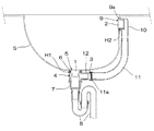
図1乃至図4に示した、本発明の第一実施例の排水配管は、槽体である洗面ボウルSに施工される排水配管であって、以下に記載する主排水管、枝排水管、逆流防止弁3を備えた継手管12、から構成され、以下に記載する洗面台に施工される。
洗面ボウルSは、上方が開口した略箱体形状を成す槽体であって、底面には後述する排水口本体5を取り付ける底面開口部H1を、側面の上端近傍には側面排水口本体9を取り付ける側面開口部H2を、それぞれ備えてなる。
主排水管は、洗面ボウルSの底面の底面開口部H1に接続され、槽体底面からの排水を下水側に排出するための配管であって、以下に記載する、排水口本体5、テールピース管7、トラップ管8、より構成されてなる。
排水口本体5は、略円筒形状を成す管体であって、上端外側面には外径方向に突出するフランジ部6を備え、該フランジ部6よりも下方の側面に管体の内外を貫通する貫通孔5aを2カ所備えてなる。また、貫通孔5aの下方の外側面には、下端まで雄ネジを備えてなる。また、施工完了時、排水口本体5の内部は槽体である洗面ボウルS内の排水を排出する排水口1を形成する。
テールピース管7は、略直線状を成す管体からなる部材であって、上端の内周部分に排水口本体5の雄ネジと螺合する雌ネジを備えてなる。
トラップ管8はS字形状に屈曲させた管体を、90度横転させた形状を成す配管部材であって、使用時にその内部に排水を溜めることによってトラップ機能と呼ばれる、下流側から上流側への臭気また害虫類の逆流を防止する機能を備えた部材である。本実施例ではJ字形状に屈曲した管体を2本組み合わせてS字形状となるように構成している。また、トラップ管8の下流側は直下方向に延出されており、トラップ管8の下流側端部と、下水側に繋がる床下配管とが接続されるように構成されてなる。
枝排水管は、洗面台の側面の上端近傍に設けられた、側面開口部H2に接続され、槽体側面からの排水を主排水管側に排出するための配管であって、以下に記載する、側面排水口本体9、エルボ管10、ホース管11、枝付き管4、継手管12、より構成されてなる。
側面排水口本体9は、略円筒形状を成す管体であって、その一端の外側面には外径方向に突出する鍔部9aを備えてなる。また、側面排水口本体9の外側面には、下龍側端部まで雄ネジを備えてなる。また、施工完了時、側面排水口本体9の内部は槽体である洗面ボウルS内の排水を排出する側面排水口2を形成する。
エルボ管10は、90度に屈曲した管体からなる部材であって、上流側の端部の内周部分に側面排水口本体9の雄ネジと螺合する雌ネジを備えてなる。
ホース管11は洗面ボウルSの外側面に沿って配置される、可撓性を備えた管体であって、一端はエルボ管10の下流側端部に接続され、他端には、内部に雌ネジを備えたナット部材11aを回動自在に備えてなる。
枝付き管4は、上下に延出された主管部4aと、該主管部4aの側面から延出された枝管部4b、から構成される管体である。この枝管部4bの端部の外周の外径は、一般的な規格品のホース管11の内の一つ(例えば管径30ミリメートル)の寸法の内径に合致するに構成されてなる。
また、後述するように、施工完了時、主管部4aの内部に、排水口本体5の一部が同心円状に収納配置される。即ち、主管部4aは、主排水管の一部である排水口本体5に沿って設けられる管体である。
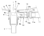
継手管12は、その内部に逆流防止弁3を構成する管体であって、以下に記載する継手管本体13と、弁本体15と、弁押え部材16と、から構成される。
継手管本体13は略円筒形状を成す管体であって、上流側端部は外側面にホース管11のナット部材11aの雌ネジと螺合する雌ネジを備えてなり、またその内部には、後述する弁本体15の回転軸15bを回動自在に収納する溝部14を備えてなる。
また、継手管本体13の下流側端部は、その内径が一般的な規格品のホース管11の内の一つの内径と同じ寸法に構成されてなる。ここでは、上記枝付き管4の枝管部4b端と同様の、管径30ミリメートルとなるように構成されている。このため、継手管本体13の上記端部は、枝付き管4の枝管部4bに対し、枝管部4b端部をその内部に収納するようにして接続することができる。
弁押え部材16は、後述する弁本体15を継手管本体13の端部からその内部に配置した後、更に継手管12端部より挿入するリング状の部材であって、溝部14に配置された回転軸15bが端部側より抜けないように押えると共に、通常時、また逆流の発生時に弁本体15の弁体15aが当接して逆流した泡の通過を防ぐ弁座部16aを備えてなる。
弁本体15は、略円盤状の部材であって、弁座部16aに当接して継手管12内の流路を閉塞する弁体15aと、該弁体15aの端部に備えられた、溝部14に回動自在に配置される回転軸15bと、から構成されてなる。
施工完了時、弁本体15が継手管本体13内に、回動自在に収納配置された場合、弁本体15の弁体15aは、通常時は自重にて垂立した状態となることで弁座部16aに当接し、排水の流路を閉塞する。このため、枝付き管4の枝管部4bから、泡等が逆流を生じても、弁本体15よりも上流側に逆流が上昇することを防止する。
一方、側面排水口2から流れてきた排水が逆流防止弁3に達した場合、排水の水圧によって弁部材は回転軸15bを中心に回転し、弁体15aが弁座部16aから離間して排水の流路を開口し、これにより排水を下流側に流出することができる。
即ち、本実施例の継手管12は、常時は閉塞し、側面排水口2から排水を生じた場合のみ開口する逆流防止弁3をその内部に備えてなる。また、本実施例では、弁本体15は回転軸15bと溝部14とを組み合わせたことでヒンジ部3aを形成する。即ち、本実施例の逆流防止弁3は、管体(継手管12)に対して回動自在に取り付けられるヒンジ部3aを備えた弁体15aからなる。
また、本実施例の排水配管は、必要に応じ排水口本体5の上端の開口を覆って閉塞する、弾性素材からなる蓋部材17を備えてなる。
Below, the 1st example of the present invention is described, referring to drawings.
The drainage pipe of the first embodiment of the present invention shown in FIG. 1 to FIG. 4 is a drainage pipe constructed in the wash bowl S that is a tank body, and includes a main drainage pipe, a branch drainage pipe described below, It is comprised from the joint pipe |
The wash bowl S is a tank body having a substantially box shape with an upper opening, and a bottom opening H1 to which a drain outlet
The main drain pipe is connected to the bottom opening H1 on the bottom surface of the wash bowl S, and is a pipe for discharging waste water from the bottom surface of the tank body to the sewage side. The
The drain outlet
The
The
The branch drain pipe is connected to a side opening H2 provided near the upper end of the side surface of the washstand, and is a pipe for discharging waste water from the tank side face to the main drain pipe side, which will be described below. , Side drain outlet
The side drainage
The
The
The
Further, as will be described later, when the construction is completed, a part of the drain outlet
The
The joint pipe
Further, the downstream end portion of the joint pipe
The
The
When the
On the other hand, when the waste water flowing from the
That is, the
Further, the drainage pipe of the present embodiment includes a
上記した各部材から構成される排水配管は、以下のようにして洗面台に施工される。
尚、本実施例において、特に詳述しない場合でも、各配管の接続箇所等は、必要に応じ接着やパッキングを利用した接続により、漏水などが生じないように構成されてなる。
始めに、工場等において、ホース管11のナット部材11aを備えない側の端部に、エルボ管10の下流側端部を接着によって水密的に接続する。
また、継手管本体13の下流側端部に、枝付き管4の枝管部4bを、接着によって水密的に接続する。
また、継手管本体13の溝部14に弁本体15の回転軸15bを収納し、更に弁押え部材16を継手管本体13内に挿入して、継手管本体13内に逆流防止弁3を構成する。
更に、ホース管11のナット部材11aの雌ネジを継手管本体13の雄ネジに螺合させて、継手管本体13をホース管11に水密的且つ着脱自在に接続する。
上記のようにして枝排水管の一部を構成した上で、施工現場に各部材を搬入し、次のようにして施工を行う。
施工現場において、まず、キャビネットや台座等を設置した上で、その上に洗面ボウルSを配置して洗面台を構成する。また、この際のキャビネット下の床面には開口が設けられ、開口部分から下水側に繋がる、床下空間に配管された床下配管に管体を接続できるように構成されてなる。
次に、洗面ボウルSの底面開口部H1に排水口本体5を挿通し、排水口本体5のフランジ部6下面と、底面開口部H1周縁の上面とが当接するように配置する。更に枝付き管4を、洗面ボウルSの下方側から配置する。この時は、枝付き管4の主管部4aの内部に、主管部4aと排水口本体5とが同心円状になるように、枝付き管4を挿通させる。また、枝管部4bが側面排水口2側を向く方に配置しておく。
次に、排水口本体5の下端から、排水口本体5の雄ネジにテールピース管7の雌ネジを螺合させて締め付けを行う。この時、枝付き管4の主管部4aは、上端は洗面ボウルSの底面開口部H1周縁の下面に、下端はテールピース管7の上端にそれぞれ水密的に当接した状態となる。
このようにして、底面開口部H1の周縁を、枝付き管4の主管部4aを介して、排水口本体5のフランジ部6とテールピース管7上面とで挟持することで、排水口本体5及びテールピース管7が洗面ボウルSに接続固定される。
次に、洗面ボウルSの側面開口部H2の周縁の裏面側に、エルボ管10の上流側端部を当接させた上で、側面排水口本体9を側面開口部H2に挿通し、側面排水口本体9の雄ネジを、エルボ管10の雌ネジに螺合させ、締め付けを行う。
このようにして、側面開口部H2の周縁を、側面排水口本体9の鍔部9aとエルボ管10の上流側端部とで挟持することで、側面排水口本体9及びエルボ管10が洗面ボウルSに接続固定される。
更に、テールピース管7の下流側端部にトラップ管8の上流側端部を接続し、トラップ管8の下流側端部を床下配管に接続して、本実施例の排水配管の、洗面台への施工が完了する。
尚、継手管12を上記のように構成・接続したことから、本実施例の排水配管は、常時は閉塞し、側面排水口2から排水を生じた場合のみ開口する逆流防止弁3を備えた継手管12を、枝管部4bの端部に接続した排水配管である。
The drainage pipe composed of each member described above is applied to the washstand as follows.
In the present embodiment, even if not specifically described, the connection locations of the respective pipes are configured so that water leakage does not occur due to connection using bonding or packing as necessary.
First, in a factory or the like, the downstream end of the
Further, the
Further, the
Further, the female thread of the
After configuring a part of the branch drainage pipe as described above, each member is carried into the construction site, and construction is performed as follows.
At the construction site, first, a cabinet, a pedestal, and the like are installed, and then a wash bowl S is arranged thereon to constitute a wash basin. Moreover, an opening is provided in the floor surface under the cabinet in this case, and the pipe body is configured to be connected to an underfloor pipe connected to the underfloor space connected from the opening portion to the sewage side.
Next, the drain outlet
Next, from the lower end of the drain port
In this way, the drain opening
Next, after the upstream end of the
In this way, by holding the peripheral edge of the side opening H2 between the
Furthermore, the upstream end of the
In addition, since the
上記のように構成した配管構造において、洗面台を使用し、洗面ボウルS内に排水が発生すると、排水は、洗面ボウルS底面に配置された排水口本体5内部の排水口1から、排水口本体5内部、テールピース管7、トラップ管8、の順に通過し、最終的には床下配管から下水側に排出される。
また、上記排水口1に、図3のように蓋部材17を配置して排水口1からの排水が行われないようにした上で、洗面ボウルS内に吐水を行うと、吐水は排出されること無く洗面ボウルS内に吐水が溜まってゆく。溜まった吐水の水位が側面排水口2の下端よりも上方に達すると、洗面ボウルS内に溜まった吐水は側面排水口2から、側面排水口本体9内部、エルボ管10、ホース管11、継手管12、枝付き管4の枝管部4b、枝付き管4の主管部4a内から排水口本体5の貫通孔5aを介して排水口本体5内に流入し、更に(排水口1からの排水の場合と同様に)テールピース管7、トラップ管8、の順に通過し、最終的には床下配管から下水側に排出される。
尚、上記のように側面排水口2から排水が行われる場合、排水が継手管12内を通過する際に、図3に示したように、排水の水圧によって継手管12の内部で弁本体15が回転軸15bを中心に回動して排水の流路を開放し、排水の通過が行われる。排水が終了し、継手管12内から排水が無くなると、弁本体15は再び弁本体15の自重によって垂立した状態となることで弁座部16aに当接し、排水の流路を閉塞する。
また、上記のようにして排水が行われ、トラップ管8内を排水が通過する際、トラップ管8の屈曲部分の内部に排水の溜まり部分が生じる。この排水の溜まり部分によって、トラップ管8内の流路には、(長期間の放置によって蒸発しない限り)排水が常に満水状態となっている箇所が発生する。この、流路が排水によって満水となった部分によって、下流側から臭気や害虫類が屋内側に逆流することが防止される。このように、下水側に繋がる配管から臭気や害虫類が屋内側に侵入することを防止する機能を「トラップ機能」と呼ぶ。また、上記トラップ管8の曲がり部分に溜まって流路を満水状態とした排水は「封水」と呼ばれる。本実施例のトラップ管8は、封水を利用してトラップ機能を生じさせた、「封水式排水トラップ」である。
In the piping structure configured as described above, when a wash basin is used and waste water is generated in the wash bowl S, the waste water is discharged from the
In addition, when the
When drainage is performed from the
In addition, drainage is performed as described above, and when the drainage passes through the
上記のように構成した配管構造において、洗面台にて石鹸・洗剤などを使用し、洗面ボウルS内に泡混じりの排水を発生させた上で、この排水を排水口1から排出した場合、泡混じりの排水は、洗面ボウルS底面に配置された排水口本体5内部の排水口1から、排水口本体5内部、テールピース管7、トラップ管8、の順に通過し、最終的には床下配管から下水側に排出される。
この場合において、排水配管上に封水式排水トラップを備えたことで、排水中の泡が下流側に流出しにくくなる状態が発生する。詳述すると、封水式排水トラップを含む配管において、排水等が封水の部分を通過して下流側に流出するためには、封水の水面よりも下方になる位置まで通過しなければならないが、泡は気体を含有している為、排水に比べて比重は相当に軽く、封水水面よりも下方に下がるためには泡と共に流れる排水の勢いが相当に強くなければならない。このため、排水の量が少なく、勢いが弱かったり、排水の終了間際で排水の流れの勢いが弱まった状態の際に流れ込む泡は、封水を超えることができず、封水よりも上流側に残留する。
この場合に、洗面ボウルS側面の排水口1からは排水が継続して流れている場合が多く、泡は封水の水面上から堆積してゆき、排水口本体5内部、貫通孔5a、枝付き管4の主管部4a内、枝管部4b、まで充満するが、本実施例では、継手管12内において、常時は閉塞し、側面排水口2から排水を生じた場合のみ開口する逆流防止弁3を備えてなる。具体的には、継手管本体13の内部において、弁本体15が弁座部16aに通常時当接すると共に、下流側から上流側へ泡の圧力が生じても、そのまま弁本体15の弁体15aが、弁座部16aに強く当接して、確実に泡の逆流を防止する。
このため、排水中に石鹸・洗剤などに由来する泡が混入していても、継手管12の逆流防止弁3によって逆流が防止され、側面排水口2から泡が逆流して溢れ出す、ということは無い。
In the piping structure configured as described above, when soap and detergent are used in the washstand and foamy wastewater is generated in the washbasin S, the wastewater is discharged from the
In this case, since the sealed drainage trap is provided on the drainage pipe, a state in which bubbles in the drainage hardly flow out to the downstream side occurs. More specifically, in a pipe including a sealed drain trap, in order for drainage and the like to pass through the sealed water and flow downstream, it must pass to a position below the surface of the sealed water. However, since the bubbles contain gas, the specific gravity is considerably lighter than that of the drainage, and the power of the drainage flowing along with the bubbles must be considerably strong in order to fall below the sealed water surface. For this reason, the amount of drainage is low, the momentum is weak, or the foam that flows in when the drainage flow is weak just before the end of drainage cannot exceed the sealed water, upstream of the sealed water To remain.
In this case, in many cases, drainage continues to flow from the
For this reason, even if bubbles derived from soap, detergent, etc. are mixed in the drainage, the
また、上記継手管12の逆流防止弁3の回動する回転軸15bのように、機械要素を備えた場合、排水中の塵芥や油分、また泡の原因となった石鹸・洗剤成分などが回転軸15b等に付着したり、また弁体15aと弁座部16aとの間に付着し弁体15aから弁座部16aを離間し難くする場合があるが、本実施例では、継手管12の端部とホース管11とをナット部材11aを利用して接続しており、ナット部材11aの螺合を緩めることで、ホース管11と継手管12とを容易に着脱・分離することができる。このようにホース管11と継手管12とを着脱・分離し、弁本体15や弁押え部材16を取り出して、各部材や継手管12内部を清掃し、再度接続を行うことで、上記の様に排水中の石鹸や洗剤、塵芥や油分等の汚濁物質などに由来する動作異常を容易に解消することができる。また、部材の破損等による動作異常が発生しても、同様にホース管11と継手管12とを容易に着脱・分離し、破損した部材(弁本体15や弁押え部材16)の交換を行う等することで、容易に修理作業を行うことができる。
即ち、本実施例では、逆流防止弁3を備えた枝排水管の管体である継手管12が、他の枝排水管の部材であるホース管11に対して着脱自在に構成され、着脱により開放された箇所から弁体15aを枝排水管外に取り出して部材交換や清掃が可能に構成されてなる。
Further, when a mechanical element is provided such as the
That is, in the present embodiment, the
次に、本発明の第二実施例を、図面を参照しつつ説明する。
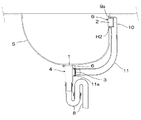
図5乃至図8に示した、本発明の第二実施例の排水配管は、槽体である洗面ボウルSに施工される排水配管であって、以下に記載する枝付き管4、トラップ管8、側面排水口本体9、エルボ管10、ホース管11、弁本体15より構成されてなる。
この内、トラップ管8、側面排水口本体9、エルボ管10、ホース管11は、段落0014に記載された第一実施例の各部材と同一の構成のため、説明は省略し、洗面ボウルS、枝付き管4、弁本体15、及び弁押え部材16の構造について説明する。
洗面ボウルSは、上方が開口した略箱体形状を成す槽体であって、底面には上下に貫通した開口からなる排水口1を、側面の上端近傍には側面排水口本体9を取り付ける側面開口部H2を、それぞれ備えてなる。また、排水口1周縁の下面には、後述するビス部材18aを螺合するためのネジ穴部18bを複数備えてなる。
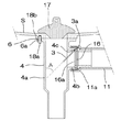
枝付き管4は、上下に延出された主管部4aと、該主管部4aの側面から延出された枝管部4b、から構成される管体であって、主管部4aの上面には外周方向に突出したフランジ部6を備え、また該フランジ部6の数カ所に、後述するビス部材18aが貫通するための穴部6aを備えてなる。
また枝管部4bの外側面にはホース管11のナット部材11aの雌ネジと螺合する雄ネジを備えてなり、またその内部には、弁本体15の回転軸15bを回動自在に収納する溝部14を備えてなる。
弁押え部材16は、後述する弁本体15を枝付き管4の枝管部4bの端部からその内部に配置した後、更に枝管部4b端部より挿入するリング状の部材であって、溝部14に配置された回転軸15bが端部側より抜けないように押えると共に、通常時、また逆流の発生時に弁本体15の弁体15aが当接して逆流した泡の通過を防ぐ弁座部16aを備えてなる。
弁本体15は、略円盤状の部材であって、弁座部16aに当接して枝管部4b内の流路を閉塞する弁体15aと、該弁体15aの端部に備えられた、溝部14に回動自在に配置される回転軸15bと、から構成されてなる。
施工完了時、弁本体15が枝管部4b内に、回動自在に収納配置された場合、弁本体15の弁体15aは、通常時は自重にて垂立した状態となることで弁座部16aに当接し、排水の流路を閉塞する。このため、枝付き管4の主管部4aから、泡等が逆流を生じても、弁本体15よりも上流側に逆流が上昇することを防止する。
一方、側面排水口2から流れてきた排水が逆流防止弁3に達した場合、排水の水圧によって弁部材は回転軸15bを中心に回転し、弁体15aが弁座部16aから離間して排水の流路を開口し、これにより排水を下流側に流出することができる。
即ち、本実施例の枝付き管4の枝管部4bは、常時は閉塞し、側面排水口2から排水を生じた場合のみ開口する逆流防止弁3をその内部に備えてなる。また、本実施例では、弁本体15は回転軸15bと溝部14とを組み合わせたことでヒンジ部3aを形成する。即ち、本実施例の逆流防止弁3は、管体(枝管部4b)に対して回動自在に取り付けられるヒンジ部3aを備えた弁体15aからなる。
また、本実施例の枝付き管4と逆流防止弁3においては、枝付き管4の枝管部4b内に弁体15aの回動の程度をコントロールする突起部分4cを設けてなる。
この突起部分4cによって、弁本体15の弁体15aは、最も開いた時(弁座部16aから離間した時)、その先端が枝付き管4の主管部4a内に突出すると共に、弁体15aの平面と、主管部4aの弁体15aに対向する面とが成す角度(図7のAで示される角度)が略45度以下となるように構成されてなる。これにより、枝管部4bを通過して主管部4a内に流入する排水は、主管部4aの弁体15aに対向する面に衝突する場合でも、弁体15aがガイドとなって45度より小さい角度で衝突することとなり、衝突の衝撃が(壁面に正面から衝突する等45度を超える角度で衝突する場合に比べ)小さくなり、本管部へ合流する際に、合流がスムーズに行われて乱流の発生を防ぎ、排水性能を良好なものとすることができる。
尚、本実施例では上記のように弁本体15の弁体15aは、最も開いた時、弁体15aの平面と、主管部4aの弁体15aに対向する面とが成す角度を略45度以下となるように構成したが、要求されるのは弁体15aにガイドされて枝管部4bを通過した排水が、対向する壁面に衝突する際に略45度以下となることであって、弁体15aを通過してから対向する壁面に衝突するまでに重力によって多少下方に屈曲するため、その分を見越して、弁体15aが最も開いた時、弁体15aの平面と、主管部4aの弁体15aに対向する面とが成す角度が55度程度までであれば、ほぼ確実に、排水が枝管部4bに対向する壁面に衝突する際に略45度以下とすることができる。もちろん、確実さを求めるのであれば、上記本実施例のように、略45度以下となるようにすることで確実に略45度以下とすることができる。
ビス部材18aは、枝付き管4を洗面ボウルS下面に取り付けるための雄ネジを備えた部材であって、枝付き管4の穴部6aを貫通した上で、洗面ボウルSの下面のネジ穴部18bに螺合するように構成されてなる。
また、本実施例の排水配管は、必要に応じ排水口本体5の上端の開口を覆って閉塞する、弾性素材からなる蓋部材17を備えてなる。
Next, a second embodiment of the present invention will be described with reference to the drawings.
The drainage pipe of the second embodiment of the present invention shown in FIGS. 5 to 8 is a drainage pipe constructed on the wash bowl S which is a tank body, and is described below with a
Among these, the
The wash bowl S is a tank body having a substantially box shape with an open top, and a side surface to which a
The
Further, the outer surface of the
The
The
When construction is completed, when the valve
On the other hand, when the waste water flowing from the
That is, the
Further, in the
By this protruding
In the present embodiment, as described above, the
The
Further, the drainage pipe of the present embodiment includes a
上記した各部材から構成される排水配管は、以下のようにして洗面台に施工される。
尚、本実施例において、特に詳述しない場合でも、各配管の接続箇所等は、必要に応じ接着やパッキングを利用した接続により、漏水などが生じないように構成されてなる。
始めに、工場等において、ホース管11のナット部材11aを備えない側の端部に、エルボ管10の下流側端部を接着によって水密的に接続する。
また、枝付き管4の溝部14に、弁本体15の回転軸15bを収納し、更に弁押え部材16を枝管部4b内に挿入して、枝管部4b内に逆流防止弁3を構成する。
更に、ホース管11のナット部材11aの雌ネジを枝付き管4の枝管部4bの雄ネジに螺合させて、枝付き管4をホース管11に水密的且つ着脱自在に接続する。
上記のようにして枝排水管の一部を構成した上で、施工現場に各部材を搬入し、次のようにして施工を行う。
施工現場において、まず、キャビネットや台座等を設置した上で、その上に洗面ボウルSを配置して洗面台を構成する。また、この際のキャビネット下の床面には開口が設けられ、開口部分から下水側に繋がる、床下空間に配管された床下配管に管体を接続できるように構成されてなる。
次に、洗面ボウルSの排水口1周縁の下面に枝付き管4のフランジ部6を当接させ、更にフランジ部6に複数設けられた穴部6aを介した上でビス部材18aをネジ穴部18bに螺合させて、枝付き管4を洗面ボウルSに接続固定する(前述のように、必要に応じてパッキングを利用し水密的に接続する)。
また、この接続の際には、枝管部4bが側面排水口2側を向く方に配置しておく。
次に、洗面ボウルSの側面開口部H2の周縁の裏面側に、エルボ管10の上流側端部を当接させた上で、側面排水口本体9を側面開口部H2に挿通し、側面排水口本体9の雄ネジを、エルボ管10の雌ネジに螺合させ、締め付けを行う。
このようにして、側面開口部H2の周縁を、側面排水口本体9の鍔部9aとエルボ管10の上流側端部とで挟持することで、側面排水口本体9及びエルボ管10が洗面ボウルSに接続固定される。
更に、枝付き管4の下端にトラップ管8の上流側端部を接続し、トラップ管8の下流側端部を床下配管に接続して、本実施例の排水配管の、洗面台への施工が完了する。
尚、枝付き管4の枝管部4bを上記のように構成・接続したことから、本実施例の排水配管は、常時は閉塞し、側面排水口2から排水を生じた場合のみ開口する逆流防止弁3を、枝付き管4の枝管部4bに備えた排水配管である。
The drainage pipe composed of each member described above is applied to the washstand as follows.
In the present embodiment, even if not specifically described, the connection locations of the respective pipes are configured so that water leakage does not occur due to connection using bonding or packing as necessary.
First, in a factory or the like, the downstream end of the
Further, the
Further, the female thread of the
After configuring a part of the branch drainage pipe as described above, each member is carried into the construction site, and construction is performed as follows.
At the construction site, first, a cabinet, a pedestal, and the like are installed, and then a wash bowl S is arranged thereon to constitute a wash basin. Moreover, an opening is provided in the floor surface under the cabinet in this case, and the pipe body is configured to be connected to an underfloor pipe connected to the underfloor space connected from the opening portion to the sewage side.
Next, the
In this connection, the
Next, after the upstream end of the
In this way, by holding the peripheral edge of the side opening H2 between the
Further, the upstream end of the
Since the
上記のように構成した配管構造において、洗面台を使用し、洗面ボウルS内に排水が発生すると、排水は、洗面ボウルS底面の排水口1から、枝付き管4の主管部4a内部、トラップ管8、の順に通過し、最終的には床下配管から下水側に排出される。
また、上記排水口1に、図7のように蓋部材17を配置して排水口1からの排水が行われないようにした上で、洗面ボウルS内に吐水を行うと、吐水は排出されること無く洗面ボウルS内に吐水が溜まってゆく。溜まった吐水の水位が側面排水口2の下端よりも上方に達すると、洗面ボウルS内に溜まった吐水は側面排水口2から、側面排水口本体9内部、エルボ管10、ホース管11、枝付き管4の枝管部4bから、(排水口1からの排水の場合と同様に)枝付き管4の主管部4a内、トラップ管8、の順に通過し、最終的には床下配管から下水側に排出される。
尚、上記のように側面排水口2から排水が行われる場合、排水が枝管部4b内を通過する際に、図7に示したように排水の水圧によって枝管部4bの内部で弁本体15が回転軸15bを中心に回動して排水の流路を開放し、排水の通過が行われる。排水が終了し、枝管部4b内から排水が無くなると、弁本体15は再び弁本体15の自重によって垂立した状態となることで弁座部16aに当接し、排水の流路を閉塞する。
また、この逆流防止弁3の弁体15aを排水が通過する際には、前述のように、突起部分4cによって弁体15aの開口の程度がコントロールされ、弁体15aの平面と、主管部4aの弁体15aに対向する面とが成す角度(図7のAで示される角度)が最大でも略45度以下となるように構成されてなる。これにより、弁体15aが一種のガイドとなって、枝管部4bに対向する主管部4aの壁面に対し、排水は45度より小さい角度で衝突することとなり、衝突の衝撃が小さくなり、本管部へ合流する際に、合流がスムーズに行われて乱流の発生を防ぎ、排水性能を良好なものとすることができる。
また、上記のようにして排水が行われた際に、トラップ管8内に排水が溜まることで、トラップ管8が、下流側からの臭気や害虫類の逆流を防止する「封水式排水トラップ」となることは、第一実施例で記載した通りである。
In the piping structure configured as described above, when a wash basin is used and wastewater is generated in the washbasin bowl S, the wastewater is discharged from the
In addition, when the
When drainage is performed from the
When drainage passes through the
Further, when drainage is performed as described above, the
上記のように構成した配管構造において、洗面台にて石鹸・洗剤などを使用し、洗面ボウルS内に泡混じりの排水を発生させた上で、この排水を排水口1から排出した場合、泡混じりの排水は、洗面ボウルS底面の排水口1から、枝付き管4の主管部4a内部、トラップ管8、の順に通過し、最終的には床下配管から下水側に排出される。
この場合において、第一実施例と同様に、排水配管上に封水式排水トラップを備えたことで、排水中の泡が下流側に流出しにくくなる状態が発生する。
この場合に、泡は封水の水面上から堆積してゆき、枝付き管4の主管部4a内部に充満するが、本実施例では枝付き管4の枝管部4b内において、常時は閉塞し、側面排水口2から排水を生じた場合のみ開口する逆流防止弁3を備えてなる。具体的には、枝管部4bの内部において、弁本体15が弁座部16aに通常時当接すると共に、下流側から上流側へ泡の圧力が生じても、そのまま弁本体15の弁体15aが、弁座部16aに強く当接して、確実に泡の逆流を防止する。
このため、排水中に石鹸・洗剤などに由来する泡が混入していても、継手管12の逆流防止弁3によって逆流が防止され、側面排水口2から泡が逆流して溢れ出す、ということは無い。
In the piping structure configured as described above, when soap and detergent are used in the washstand and foamy wastewater is generated in the washbasin S, the wastewater is discharged from the
In this case, as in the first embodiment, the provision of the sealed drain trap on the drain pipe causes a state in which bubbles in the drain are less likely to flow downstream.
In this case, the foam accumulates from the surface of the sealed water and fills the inside of the
For this reason, even if bubbles derived from soap, detergent, etc. are mixed in the drainage, the
また、上記枝管部4bの逆流防止弁3が、第一実施例と同様に、排水中の塵芥や油分、また泡の原因となった石鹸・洗剤成分などの汚濁物質、また弁本体15の破損等によって動作異常を生じる場合があるが、本実施例では、枝管部4bの端部とホース管11とをナット部材11aを利用して接続しており、ナット部材11aの螺合を緩めることで、ホース管11と枝管部4bとを容易に着脱・分離することができる。これにより、弁本体15や弁押え部材16を取り出して各部材や枝管部4b内部を清掃し、また弁本体15や弁押え部材16が破損していた場合は部材の交換を行う等した上で、再度ホース管11と枝管部4bとを接続することで、容易に動作異常を解消したり、破損の修理作業を行うことができる。
即ち、本実施例では、逆流防止弁3を備えた枝排水管の管体である枝管部4bが、他の枝排水管の部材であるホース管11に対して着脱自在に構成され、着脱により開放された箇所から弁体15aを枝排水管外に取り出して部材交換や清掃が可能に構成されてなる。
In addition, the
That is, in this embodiment, the
本発明の実施例は以上のようであるが、本発明は上記実施例に限定される物ではなく、主旨を変更しない範囲において自由に変更が可能である。
例えば上記実施例においては、排水配管が施工される排水機器は洗面台の洗面ボウルSであるが、本発明は上記実施例に限定されるものでは無く、浴槽の排水配管や、流し台の排水配管など、どの様な排水機器の排水配管に採用しても構わない。
また、上記実施例では、枝付き管4の主管部4aを鉛直方向に、枝管部4bを水平方向に、それぞれ配置してなるが、本発明は上記実施例に限定されるものでは無く、主管部4aを水平方向に、枝管部4bを略鉛直方向に配置する等しても構わない。
また、上記実施例では、枝付き管4の主管部4aと枝管部4bとはほぼ90度となるように構成されてなるが、本発明は上記実施例に限定されるものでは無く、主管部4aに対して枝管部を例えば70度など傾斜する角度にて構成しても構わない。
また、上記実施例では、逆流防止弁3を側面排水口2からの流路上に配置して構成してなるが、本発明は上記実施例に限定されるものでは無く、排水口1からの流路上であって、側面排水口2からの排水が合流する開口箇所に逆流防止弁3を配置するように構成しても構わない。
The embodiments of the present invention are as described above. However, the present invention is not limited to the above-described embodiments, and can be freely changed without departing from the scope of the present invention.
For example, in the above embodiment, the drainage device on which the drainage pipe is constructed is the washbasin bowl S of the washstand, but the present invention is not limited to the above embodiment, and the drainage pipe of the bathtub or the drainage pipe of the sink For example, it may be used for drainage piping of any drainage equipment.
Moreover, in the said Example, although the
Moreover, in the said Example, although the
Moreover, in the said Example, although the
1 排水口 2 側面排水口
3 逆流防止弁 3a ヒンジ部
4 枝付き管 4a 主管部
4b 枝管部 4c 突起部分
5 排水口本体 5a 貫通孔
6 フランジ部 6a 穴部
7 テールピース管 8 トラップ管
9 側面排水口本体 9a 鍔部
10 エルボ管 11 ホース管
11a ナット部材 12 継手管
13 継手管本体 14 溝部
15 弁本体 15a 弁体
15b 回転軸 16 弁押え部材
16a 弁座部 17 蓋部材
18a ビス部材 18b ネジ穴部
S 洗面ボウル H1 底面開口部
H2 側面開口部
DESCRIPTION OF
Claims (7)
槽体の側面に設けられた側面排水口と、
排水口からの排水を下水側に排出する主排水管と、
側面排水口からの排水を主排水管の途中部分に排出する枝排水管と、
からなる槽体の排水配管において、
常時閉塞して排水口からの泡の逆流が側面排水口に生じることを防止すると共に、側面排水口から排水を生じた場合のみ開口して主排水管側への通水を行う逆流防止弁を備えたことを特徴とする排水配管。 A drain outlet provided on the bottom of the tank body;
A side drain provided on the side of the tank body;
A main drain pipe that discharges drainage from the drain to the sewage side;
A branch drainage pipe that drains the drainage from the side drainage port to the middle part of the main drainage pipe,
In the drainage pipe of the tank body consisting of
A backflow prevention valve that is always closed to prevent backflow of bubbles from the drainage outlet to the side drainage outlet and opens only when drainage is generated from the side drainage outlet and allows water to flow to the main drainage pipe side. Drainage pipe characterized by having.
主排水管上に設けられるか、又は主排水管に沿って設けられる管体である主管部、該主管部の側面から延出された枝管部、からなる枝付き管を備え、
枝付き管の主管部は主排水管側に、枝管部は側面排水口からの配管に、それぞれ接続されると共に、
枝管部内に逆流防止弁を備えたことを特徴とする、請求項1又は請求項2に記載の排水配管。 In the above drain pipe,
Provided with a branch pipe comprising a main pipe portion which is provided on the main drain pipe or a pipe body provided along the main drain pipe, a branch pipe portion extending from a side surface of the main pipe portion,
The main pipe part of the branch pipe is connected to the main drain pipe side, the branch pipe part is connected to the pipe from the side drain port,
The drainage pipe according to claim 1 or 2, wherein a backflow prevention valve is provided in the branch pipe part.
主排水管上に設けられるか、又は主排水管に沿って設けられる管体である主管部、該主管部の側面から延出された枝管部、からなる枝付き管を備え、
枝付き管の主管部は主排水管側に、枝管部は側面排水口からの配管に、それぞれ接続されると共に、
枝管部の端部に、逆流防止弁を備えた継手管を接続することを特徴とする、請求項1又は請求項2に記載の排水配管。 In the above drain pipe,
Provided with a branch pipe comprising a main pipe portion which is provided on the main drain pipe or a pipe body provided along the main drain pipe, a branch pipe portion extending from a side surface of the main pipe portion,
The main pipe part of the branch pipe is connected to the main drain pipe side, the branch pipe part is connected to the pipe from the side drain port,
The drainage pipe according to claim 1 or 2, wherein a joint pipe having a backflow prevention valve is connected to an end of the branch pipe part.
板状の弁体と、
該弁体を管体に対して回動自在に取り付けられるヒンジ部と、
管体に備えられた、弁体が当接する弁座部と、
からなり、
通常時は弁体が管体内面に接して、逆流した排水や排水中の泡の通過を防止すると共に、
排水時には管体内面から離間して側面排水口からの排水や排水中の泡を通過させて排水を行うことを特徴とする、請求項1乃至請求項4のいずれか一つに記載の排水配管。 In the drainage pipe, the backflow prevention valve is
A plate-shaped valve body;
A hinge portion for rotatably attaching the valve body to the tube body;
A valve seat provided on the tube body and in contact with the valve body;
Consists of
Normally, the valve body is in contact with the inner surface of the tube to prevent the backflowing drainage and the passage of bubbles in the drainage,
The drainage pipe according to any one of claims 1 to 4, wherein drainage is performed by draining water from a side drainage port or passing bubbles in drainage while being separated from the inner surface of the pipe body during drainage. .
逆流防止弁を備えた管体が、他の枝排水管の部材に対して着脱自在に構成され、着脱により開放された箇所から弁体を枝排水管外に取り出し可能に構成したことを特徴とする、請求項に記載の排水配管。 In the above drain pipe,
The pipe body provided with the backflow prevention valve is configured to be detachable with respect to other branch drainage pipe members, and the valve body can be taken out of the branch drainage pipe from a position opened by the detachment. The drainage pipe according to claim.
逆流防止弁の弁体の開き角度に制限を行い、弁体を通過した排水が、弁体に対向する管体の壁面に対して略45度よりも小さい角度にて衝突するようにしたことを特徴とする、請求項1乃至請求項6のいずれか一つに記載の排水配管。 In the above drain pipe,
The opening angle of the valve body of the backflow prevention valve is limited so that the drainage that has passed through the valve body collides with the wall surface of the pipe body facing the valve body at an angle smaller than about 45 degrees. The drainage pipe according to any one of claims 1 to 6, wherein the drainage pipe is characterized.
Priority Applications (1)
| Application Number | Priority Date | Filing Date | Title |
|---|---|---|---|
| JP2016038383A JP6936423B2 (en) | 2016-02-29 | 2016-02-29 | Drainage piping |
Applications Claiming Priority (1)
| Application Number | Priority Date | Filing Date | Title |
|---|---|---|---|
| JP2016038383A JP6936423B2 (en) | 2016-02-29 | 2016-02-29 | Drainage piping |
Publications (2)
| Publication Number | Publication Date |
|---|---|
| JP2017155455A true JP2017155455A (en) | 2017-09-07 |
| JP6936423B2 JP6936423B2 (en) | 2021-09-15 |
Family
ID=59808270
Family Applications (1)
| Application Number | Title | Priority Date | Filing Date |
|---|---|---|---|
| JP2016038383A Active JP6936423B2 (en) | 2016-02-29 | 2016-02-29 | Drainage piping |
Country Status (1)
| Country | Link |
|---|---|
| JP (1) | JP6936423B2 (en) |
Cited By (2)
| Publication number | Priority date | Publication date | Assignee | Title |
|---|---|---|---|---|
| JP2019055065A (en) * | 2017-09-21 | 2019-04-11 | Toto株式会社 | Sanitary equipment |
| JP2020002661A (en) * | 2018-06-28 | 2020-01-09 | 丸一株式会社 | Drainage piping for drainage equipment |
Citations (6)
| Publication number | Priority date | Publication date | Assignee | Title |
|---|---|---|---|---|
| JPS50106723U (en) * | 1974-01-25 | 1975-09-02 | ||
| JP2004003313A (en) * | 2002-04-10 | 2004-01-08 | Noriatsu Kojima | Drain pipe joint |
| JP2004250911A (en) * | 2003-02-18 | 2004-09-09 | Kagami:Kk | Drainage trap |
| JP2006265971A (en) * | 2005-03-24 | 2006-10-05 | Matsushita Electric Works Ltd | Structure for preventing water from flowing back to water flow type bowl via overflow pipe |
| JP2008121338A (en) * | 2006-11-14 | 2008-05-29 | Shin Meiwa Ind Co Ltd | Check valve structure |
| JP2015068039A (en) * | 2013-09-30 | 2015-04-13 | 株式会社Lixil | Drainage system of water tank |
-
2016
- 2016-02-29 JP JP2016038383A patent/JP6936423B2/en active Active
Patent Citations (6)
| Publication number | Priority date | Publication date | Assignee | Title |
|---|---|---|---|---|
| JPS50106723U (en) * | 1974-01-25 | 1975-09-02 | ||
| JP2004003313A (en) * | 2002-04-10 | 2004-01-08 | Noriatsu Kojima | Drain pipe joint |
| JP2004250911A (en) * | 2003-02-18 | 2004-09-09 | Kagami:Kk | Drainage trap |
| JP2006265971A (en) * | 2005-03-24 | 2006-10-05 | Matsushita Electric Works Ltd | Structure for preventing water from flowing back to water flow type bowl via overflow pipe |
| JP2008121338A (en) * | 2006-11-14 | 2008-05-29 | Shin Meiwa Ind Co Ltd | Check valve structure |
| JP2015068039A (en) * | 2013-09-30 | 2015-04-13 | 株式会社Lixil | Drainage system of water tank |
Cited By (5)
| Publication number | Priority date | Publication date | Assignee | Title |
|---|---|---|---|---|
| JP2019055065A (en) * | 2017-09-21 | 2019-04-11 | Toto株式会社 | Sanitary equipment |
| JP6991457B2 (en) | 2017-09-21 | 2022-01-12 | Toto株式会社 | Sanitary equipment |
| JP2022028944A (en) * | 2017-09-21 | 2022-02-16 | Toto株式会社 | Sanitary equipment |
| JP2020002661A (en) * | 2018-06-28 | 2020-01-09 | 丸一株式会社 | Drainage piping for drainage equipment |
| JP7138319B2 (en) | 2018-06-28 | 2022-09-16 | 丸一株式会社 | Drainage piping for drainage equipment |
Also Published As
| Publication number | Publication date |
|---|---|
| JP6936423B2 (en) | 2021-09-15 |
Similar Documents
| Publication | Publication Date | Title |
|---|---|---|
| JP5597831B2 (en) | Drainage pipes and drainage traps for drainage equipment | |
| JP5291404B2 (en) | Siphon drainage system | |
| JP2015507113A (en) | Installation structure and installation method of pop-up device for basin | |
| JP2017155455A (en) | Drain piping | |
| JP5651830B2 (en) | Connection structure between tank and drainage | |
| JP6060344B2 (en) | Waterproof pan and tank | |
| JP4797205B2 (en) | Drain trap | |
| JP2013100716A (en) | Drain pipe for draining device, and drain trap | |
| JP2012136915A (en) | Water supply equipment | |
| JP2013014947A (en) | Drainage piping | |
| JP4399522B2 (en) | Overflow device | |
| JP2006265971A (en) | Structure for preventing water from flowing back to water flow type bowl via overflow pipe | |
| JP2003253722A (en) | Drainage structure of bathroom unit | |
| KR101401231B1 (en) | Drain apparatus for a washbowl | |
| KR200440682Y1 (en) | Preventing device for flowing backward wastewater of dish washer | |
| KR20160081050A (en) | I type drain trap with float ball and sink unit with the same | |
| JP3711192B2 (en) | Drainage equipment | |
| JP4206437B2 (en) | Drainage equipment | |
| JP2015078500A (en) | Drainage member | |
| FI92743C (en) | Odor trap and drain flushing device | |
| JP6040354B2 (en) | Drainage equipment | |
| KR20100005037U (en) | Drain Trap Combined with Coupling Socket | |
| KR100218648B1 (en) | A toilet bowl | |
| JP2018096167A (en) | Toilet bowl device | |
| JP3116422U (en) | Wastewater supply switching device |
Legal Events
| Date | Code | Title | Description |
|---|---|---|---|
| A621 | Written request for application examination |
Free format text: JAPANESE INTERMEDIATE CODE: A621 Effective date: 20190125 |
|
| A977 | Report on retrieval |
Free format text: JAPANESE INTERMEDIATE CODE: A971007 Effective date: 20191113 |
|
| A131 | Notification of reasons for refusal |
Free format text: JAPANESE INTERMEDIATE CODE: A131 Effective date: 20191224 |
|
| A521 | Request for written amendment filed |
Free format text: JAPANESE INTERMEDIATE CODE: A523 Effective date: 20200220 |
|
| A131 | Notification of reasons for refusal |
Free format text: JAPANESE INTERMEDIATE CODE: A131 Effective date: 20200714 |
|
| A521 | Request for written amendment filed |
Free format text: JAPANESE INTERMEDIATE CODE: A523 Effective date: 20200909 |
|
| A131 | Notification of reasons for refusal |
Free format text: JAPANESE INTERMEDIATE CODE: A131 Effective date: 20201208 |
|
| A521 | Request for written amendment filed |
Free format text: JAPANESE INTERMEDIATE CODE: A523 Effective date: 20210118 |
|
| TRDD | Decision of grant or rejection written | ||
| A01 | Written decision to grant a patent or to grant a registration (utility model) |
Free format text: JAPANESE INTERMEDIATE CODE: A01 Effective date: 20210518 |
|
| A61 | First payment of annual fees (during grant procedure) |
Free format text: JAPANESE INTERMEDIATE CODE: A61 Effective date: 20210525 |
|
| R150 | Certificate of patent or registration of utility model |
Ref document number: 6936423 Country of ref document: JP Free format text: JAPANESE INTERMEDIATE CODE: R150 |