JP2017154709A - Pneumatic tire - Google Patents
Pneumatic tire Download PDFInfo
- Publication number
- JP2017154709A JP2017154709A JP2016042415A JP2016042415A JP2017154709A JP 2017154709 A JP2017154709 A JP 2017154709A JP 2016042415 A JP2016042415 A JP 2016042415A JP 2016042415 A JP2016042415 A JP 2016042415A JP 2017154709 A JP2017154709 A JP 2017154709A
- Authority
- JP
- Japan
- Prior art keywords
- sipe
- axial direction
- composite
- tire
- pneumatic tire
- Prior art date
- Legal status (The legal status is an assumption and is not a legal conclusion. Google has not performed a legal analysis and makes no representation as to the accuracy of the status listed.)
- Granted
Links
- 239000002131 composite material Substances 0.000 claims abstract description 63
- 238000009826 distribution Methods 0.000 description 9
- 150000001875 compounds Chemical class 0.000 description 5
- 238000012360 testing method Methods 0.000 description 5
- 230000000694 effects Effects 0.000 description 4
- 230000000052 comparative effect Effects 0.000 description 3
- 238000006073 displacement reaction Methods 0.000 description 3
- XLYOFNOQVPJJNP-UHFFFAOYSA-N water Substances O XLYOFNOQVPJJNP-UHFFFAOYSA-N 0.000 description 3
- 238000004891 communication Methods 0.000 description 2
- 230000007423 decrease Effects 0.000 description 1
- 230000003247 decreasing effect Effects 0.000 description 1
- 238000013461 design Methods 0.000 description 1
- 238000011161 development Methods 0.000 description 1
- 230000000737 periodic effect Effects 0.000 description 1
- 230000003014 reinforcing effect Effects 0.000 description 1
- 238000010998 test method Methods 0.000 description 1
Images


Classifications
-
- B—PERFORMING OPERATIONS; TRANSPORTING
- B60—VEHICLES IN GENERAL
- B60C—VEHICLE TYRES; TYRE INFLATION; TYRE CHANGING; CONNECTING VALVES TO INFLATABLE ELASTIC BODIES IN GENERAL; DEVICES OR ARRANGEMENTS RELATED TO TYRES
- B60C11/00—Tyre tread bands; Tread patterns; Anti-skid inserts
- B60C11/03—Tread patterns
- B60C11/12—Tread patterns characterised by the use of narrow slits or incisions, e.g. sipes
- B60C11/1259—Depth of the sipe
- B60C11/1263—Depth of the sipe different within the same sipe
-
- B—PERFORMING OPERATIONS; TRANSPORTING
- B60—VEHICLES IN GENERAL
- B60C—VEHICLE TYRES; TYRE INFLATION; TYRE CHANGING; CONNECTING VALVES TO INFLATABLE ELASTIC BODIES IN GENERAL; DEVICES OR ARRANGEMENTS RELATED TO TYRES
- B60C11/00—Tyre tread bands; Tread patterns; Anti-skid inserts
- B60C11/03—Tread patterns
- B60C11/0304—Asymmetric patterns
-
- B—PERFORMING OPERATIONS; TRANSPORTING
- B60—VEHICLES IN GENERAL
- B60C—VEHICLE TYRES; TYRE INFLATION; TYRE CHANGING; CONNECTING VALVES TO INFLATABLE ELASTIC BODIES IN GENERAL; DEVICES OR ARRANGEMENTS RELATED TO TYRES
- B60C11/00—Tyre tread bands; Tread patterns; Anti-skid inserts
- B60C11/03—Tread patterns
- B60C11/0306—Patterns comprising block rows or discontinuous ribs
-
- B—PERFORMING OPERATIONS; TRANSPORTING
- B60—VEHICLES IN GENERAL
- B60C—VEHICLE TYRES; TYRE INFLATION; TYRE CHANGING; CONNECTING VALVES TO INFLATABLE ELASTIC BODIES IN GENERAL; DEVICES OR ARRANGEMENTS RELATED TO TYRES
- B60C11/00—Tyre tread bands; Tread patterns; Anti-skid inserts
- B60C11/03—Tread patterns
- B60C11/04—Tread patterns in which the raised area of the pattern consists only of continuous circumferential ribs, e.g. zig-zag
-
- B—PERFORMING OPERATIONS; TRANSPORTING
- B60—VEHICLES IN GENERAL
- B60C—VEHICLE TYRES; TYRE INFLATION; TYRE CHANGING; CONNECTING VALVES TO INFLATABLE ELASTIC BODIES IN GENERAL; DEVICES OR ARRANGEMENTS RELATED TO TYRES
- B60C11/00—Tyre tread bands; Tread patterns; Anti-skid inserts
- B60C11/03—Tread patterns
- B60C11/12—Tread patterns characterised by the use of narrow slits or incisions, e.g. sipes
- B60C11/1204—Tread patterns characterised by the use of narrow slits or incisions, e.g. sipes with special shape of the sipe
-
- B—PERFORMING OPERATIONS; TRANSPORTING
- B60—VEHICLES IN GENERAL
- B60C—VEHICLE TYRES; TYRE INFLATION; TYRE CHANGING; CONNECTING VALVES TO INFLATABLE ELASTIC BODIES IN GENERAL; DEVICES OR ARRANGEMENTS RELATED TO TYRES
- B60C11/00—Tyre tread bands; Tread patterns; Anti-skid inserts
- B60C11/03—Tread patterns
- B60C11/12—Tread patterns characterised by the use of narrow slits or incisions, e.g. sipes
- B60C11/1236—Tread patterns characterised by the use of narrow slits or incisions, e.g. sipes with special arrangements in the tread pattern
- B60C11/125—Tread patterns characterised by the use of narrow slits or incisions, e.g. sipes with special arrangements in the tread pattern arranged at the groove bottom
-
- B—PERFORMING OPERATIONS; TRANSPORTING
- B60—VEHICLES IN GENERAL
- B60C—VEHICLE TYRES; TYRE INFLATION; TYRE CHANGING; CONNECTING VALVES TO INFLATABLE ELASTIC BODIES IN GENERAL; DEVICES OR ARRANGEMENTS RELATED TO TYRES
- B60C11/00—Tyre tread bands; Tread patterns; Anti-skid inserts
- B60C11/03—Tread patterns
- B60C11/12—Tread patterns characterised by the use of narrow slits or incisions, e.g. sipes
- B60C11/1272—Width of the sipe
-
- B—PERFORMING OPERATIONS; TRANSPORTING
- B60—VEHICLES IN GENERAL
- B60C—VEHICLE TYRES; TYRE INFLATION; TYRE CHANGING; CONNECTING VALVES TO INFLATABLE ELASTIC BODIES IN GENERAL; DEVICES OR ARRANGEMENTS RELATED TO TYRES
- B60C11/00—Tyre tread bands; Tread patterns; Anti-skid inserts
- B60C11/03—Tread patterns
- B60C11/13—Tread patterns characterised by the groove cross-section, e.g. for buttressing or preventing stone-trapping
- B60C11/1369—Tie bars for linking block elements and bridging the groove
-
- B—PERFORMING OPERATIONS; TRANSPORTING
- B60—VEHICLES IN GENERAL
- B60C—VEHICLE TYRES; TYRE INFLATION; TYRE CHANGING; CONNECTING VALVES TO INFLATABLE ELASTIC BODIES IN GENERAL; DEVICES OR ARRANGEMENTS RELATED TO TYRES
- B60C11/00—Tyre tread bands; Tread patterns; Anti-skid inserts
- B60C11/03—Tread patterns
- B60C11/13—Tread patterns characterised by the groove cross-section, e.g. for buttressing or preventing stone-trapping
- B60C11/1376—Three dimensional block surfaces departing from the enveloping tread contour
- B60C11/1384—Three dimensional block surfaces departing from the enveloping tread contour with chamfered block corners
-
- B—PERFORMING OPERATIONS; TRANSPORTING
- B60—VEHICLES IN GENERAL
- B60C—VEHICLE TYRES; TYRE INFLATION; TYRE CHANGING; CONNECTING VALVES TO INFLATABLE ELASTIC BODIES IN GENERAL; DEVICES OR ARRANGEMENTS RELATED TO TYRES
- B60C11/00—Tyre tread bands; Tread patterns; Anti-skid inserts
- B60C11/03—Tread patterns
- B60C11/13—Tread patterns characterised by the groove cross-section, e.g. for buttressing or preventing stone-trapping
- B60C11/1376—Three dimensional block surfaces departing from the enveloping tread contour
- B60C11/1392—Three dimensional block surfaces departing from the enveloping tread contour with chamfered block edges
-
- B—PERFORMING OPERATIONS; TRANSPORTING
- B60—VEHICLES IN GENERAL
- B60C—VEHICLE TYRES; TYRE INFLATION; TYRE CHANGING; CONNECTING VALVES TO INFLATABLE ELASTIC BODIES IN GENERAL; DEVICES OR ARRANGEMENTS RELATED TO TYRES
- B60C11/00—Tyre tread bands; Tread patterns; Anti-skid inserts
- B60C11/03—Tread patterns
- B60C2011/0337—Tread patterns characterised by particular design features of the pattern
- B60C2011/0339—Grooves
- B60C2011/0341—Circumferential grooves
-
- B—PERFORMING OPERATIONS; TRANSPORTING
- B60—VEHICLES IN GENERAL
- B60C—VEHICLE TYRES; TYRE INFLATION; TYRE CHANGING; CONNECTING VALVES TO INFLATABLE ELASTIC BODIES IN GENERAL; DEVICES OR ARRANGEMENTS RELATED TO TYRES
- B60C11/00—Tyre tread bands; Tread patterns; Anti-skid inserts
- B60C11/03—Tread patterns
- B60C2011/0337—Tread patterns characterised by particular design features of the pattern
- B60C2011/0339—Grooves
- B60C2011/0358—Lateral grooves, i.e. having an angle of 45 to 90 degees to the equatorial plane
-
- B—PERFORMING OPERATIONS; TRANSPORTING
- B60—VEHICLES IN GENERAL
- B60C—VEHICLE TYRES; TYRE INFLATION; TYRE CHANGING; CONNECTING VALVES TO INFLATABLE ELASTIC BODIES IN GENERAL; DEVICES OR ARRANGEMENTS RELATED TO TYRES
- B60C11/00—Tyre tread bands; Tread patterns; Anti-skid inserts
- B60C11/03—Tread patterns
- B60C2011/0337—Tread patterns characterised by particular design features of the pattern
- B60C2011/0386—Continuous ribs
- B60C2011/0388—Continuous ribs provided at the equatorial plane
-
- B—PERFORMING OPERATIONS; TRANSPORTING
- B60—VEHICLES IN GENERAL
- B60C—VEHICLE TYRES; TYRE INFLATION; TYRE CHANGING; CONNECTING VALVES TO INFLATABLE ELASTIC BODIES IN GENERAL; DEVICES OR ARRANGEMENTS RELATED TO TYRES
- B60C11/00—Tyre tread bands; Tread patterns; Anti-skid inserts
- B60C11/03—Tread patterns
- B60C11/12—Tread patterns characterised by the use of narrow slits or incisions, e.g. sipes
- B60C11/1259—Depth of the sipe
- B60C2011/1268—Depth of the sipe being different from sipe to sipe
-
- B—PERFORMING OPERATIONS; TRANSPORTING
- B60—VEHICLES IN GENERAL
- B60C—VEHICLE TYRES; TYRE INFLATION; TYRE CHANGING; CONNECTING VALVES TO INFLATABLE ELASTIC BODIES IN GENERAL; DEVICES OR ARRANGEMENTS RELATED TO TYRES
- B60C11/00—Tyre tread bands; Tread patterns; Anti-skid inserts
- B60C11/03—Tread patterns
- B60C11/12—Tread patterns characterised by the use of narrow slits or incisions, e.g. sipes
- B60C11/1272—Width of the sipe
- B60C2011/1286—Width of the sipe being different from sipe to sipe
Abstract
Description
本発明は、ドライ路面での操縦安定性と、氷雪路面での走行性能とを向上させた空気入りタイヤに関する。 The present invention relates to a pneumatic tire with improved driving stability on a dry road surface and running performance on an icy and snowy road surface.
下記特許文献1には、雪上性能を高めるために、陸部にサイプが設けられた空気入りタイヤが提案されている。しかしながら、上記サイプは、直線状又はL字状であり、特定の方向についてしか摩擦力向上効果が得られないという問題があった。また、単にサイプを設けるだけでは、陸部の剛性が低下し、ひいてはドライ路面での操縦安定性が低下する傾向があった。 Patent Document 1 below proposes a pneumatic tire in which a sipe is provided on a land portion in order to improve performance on snow. However, the sipe is linear or L-shaped, and there is a problem that the effect of improving the frictional force can be obtained only in a specific direction. Further, simply providing sipes has a tendency to reduce the rigidity of the land portion and, consequently, the steering stability on the dry road surface.
本発明は、以上のような問題点に鑑み案出なされたもので、サイプの形状等を改善することを基本として、ドライ路面での操縦安定性と、氷雪路面での走行性能とを向上させた空気入りタイヤを提供することを主たる目的としている。 The present invention has been devised in view of the above problems, and is based on improving the shape of the sipe and the like, and improves driving stability on dry road surfaces and driving performance on icy and snowy road surfaces. The main purpose is to provide a pneumatic tire.
本発明は、トレッド部に、タイヤ周方向にのびる陸部が設けられた空気入りタイヤであって、前記陸部には、前記陸部のタイヤ軸方向の一方の端縁から他方の端縁に向かって直線状にのびる直線部と、前記直線部から前記他方の端縁までの間を円弧状に湾曲してのびる円弧部とを含む複合サイプが複数設けられ、前記複数の複合サイプは、前記円弧部の最大深さが前記直線部の最大深さよりも大きい第1複合サイプと、前記直線部の最大深さが前記円弧部の最大深さよりも大きい第2複合サイプとを含んでいることを特徴とするのが望ましい。 The present invention is a pneumatic tire in which a tread portion is provided with a land portion extending in a tire circumferential direction, and the land portion has a tire axial direction from one end edge to the other end edge of the land portion. A plurality of composite sipes including a straight portion extending linearly and an arc portion extending in a circular arc from the straight portion to the other edge, wherein the plurality of composite sipes are A first composite sipe in which the maximum depth of the arc portion is greater than the maximum depth of the linear portion; and a second composite sipe in which the maximum depth of the linear portion is greater than the maximum depth of the arc portion. It is desirable to have a feature.
本発明の空気入りタイヤにおいて、前記直線部は、タイヤ軸方向に対して30〜40°の角度で傾斜しているのが望ましい。 In the pneumatic tire of the present invention, it is desirable that the straight portion is inclined at an angle of 30 to 40 ° with respect to the tire axial direction.
本発明の空気入りタイヤにおいて、タイヤ軸方向に対する前記円弧部の角度は、前記他方の端縁から前記直線部に向かって漸減しているのが望ましい。 In the pneumatic tire of the present invention, it is desirable that the angle of the arc portion with respect to the tire axial direction is gradually decreased from the other end edge toward the straight portion.
本発明の空気入りタイヤにおいて、前記直線部のタイヤ軸方向の長さは、前記円弧部のタイヤ軸方向の長さよりも大きいのが望ましい。 In the pneumatic tire of the present invention, it is preferable that the length of the linear portion in the tire axial direction is larger than the length of the arc portion in the tire axial direction.
本発明の空気入りタイヤにおいて、前記陸部は、前記陸部の全幅を横切ってのびる横溝で区分された複数のブロックを含み、前記各ブロックには、前記第1複合サイプ及び前記第2複合サイプが設けられているのが望ましい。 In the pneumatic tire of the present invention, the land portion includes a plurality of blocks divided by transverse grooves that extend across the entire width of the land portion, and each of the blocks includes the first composite sipe and the second composite sipe. It is desirable to be provided.
本発明の空気入りタイヤにおいて、前記各ブロックには、前記第1複合サイプと前記第2複合サイプとの間を連通する縦サイプが設けられているのが望ましい。 In the pneumatic tire of the present invention, it is desirable that each block is provided with a vertical sipe that communicates between the first composite sipe and the second composite sipe.
本発明の空気入りタイヤにおいて、前記横溝は、溝底が隆起したタイバーがタイヤ軸方向の一方側に設けられた第1横溝と、前記タイバーがタイヤ軸方向の他方側に設けられた第2横溝とを含み、前記ブロックは、前記第1横溝と前記第2横溝との間に設けられているのが望ましい。 In the pneumatic tire of the present invention, the lateral groove includes a first lateral groove in which a tie bar having a raised groove bottom is provided on one side in the tire axial direction, and a second lateral groove in which the tie bar is provided on the other side in the tire axial direction. The block is preferably provided between the first lateral groove and the second lateral groove.
本発明の空気入りタイヤにおいて、前記タイバーには、溝底サイプが設けられているのが望ましい。 In the pneumatic tire of the present invention, it is preferable that the tie bar is provided with a groove bottom sipe.
本発明の空気入りタイヤの陸部には、陸部のタイヤ軸方向の一方の端縁から他方の端縁に向かって直線状にのびる直線部と、前記直線部から前記他方の端縁までの間を円弧状に湾曲してのびる円弧部とを含む複合サイプが複数設けられている。このような複合サイプは、円弧部のエッジが、直線部が提供する摩擦力とは異なる方向の摩擦力を提供し、ひいては氷雪路面での操縦安定性が高められる。しかも、複合サイプは、円弧部を含んでいるため、タイヤ走行時において互いに向き合うサイプ壁が接触したとき、陸部の見かけの横剛性を高めることができる。このため、ドライ路面での操縦安定性が維持される。 The land portion of the pneumatic tire of the present invention includes a straight portion extending linearly from one end edge in the tire axial direction of the land portion to the other end edge, and from the straight portion to the other end edge. A plurality of composite sipes including a circular arc part extending in a circular arc shape is provided. In such a composite sipe, the edge of the arc portion provides a frictional force in a direction different from the frictional force provided by the linear portion, and as a result, the handling stability on the ice and snow road surface is improved. Moreover, since the composite sipe includes an arc portion, the apparent lateral rigidity of the land portion can be increased when the sipe walls facing each other contact each other during tire traveling. For this reason, steering stability on the dry road surface is maintained.
複数の複合サイプは、円弧部の最大深さが直線部の最大深さよりも大きい第1複合サイプと、直線部の最大深さが円弧部の最大深さよりも大きい第2複合サイプとを含んでいる。このような第1複合サイプ及び第2複合サイプは、深さが異なる直線部及び円弧部を含んでいるため、深さが小さい部分によって陸部の剛性を維持することができ、深さが大きい部分によってエッジによる大きい摩擦力を提供することができる。このため、ドライ路面での操縦安定性と氷雪路面での走行性能とがバランス良く高められる。また、このような第1複合サイプ及び第2複合サイプは、陸部の剛性を維持する部分を分散させるため、陸部の剛性分布を均一にし、ひいては陸部の偏摩耗が抑制される。 The plurality of composite sipes include a first composite sipe in which the maximum depth of the arc portion is greater than the maximum depth of the straight portion, and a second composite sipe in which the maximum depth of the straight portion is greater than the maximum depth of the arc portion. Yes. Since such a 1st compound sipe and a 2nd compound sipe contain the linear part and circular arc part from which depth differs, the rigidity of a land part can be maintained by the part with small depth, and depth is large. The part can provide a large frictional force due to the edge. For this reason, steering stability on a dry road surface and running performance on an icy and snowy road surface can be improved in a well-balanced manner. Moreover, since such a 1st composite sipe and a 2nd composite sipe distribute the part which maintains the rigidity of a land part, the rigidity distribution of a land part is made uniform, and the uneven wear of a land part is suppressed by extension.
以下、本発明の実施の一形態が図面に基づき説明される。
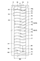
図1は、本発明の一実施形態を示す空気入りタイヤ1のトレッド部2の展開図である。本実施形態の空気入りタイヤ(以下、単に「タイヤ」ということがある)1は、例えば、冬用の乗用車用タイヤとして好適に用いられる。
Hereinafter, an embodiment of the present invention will be described with reference to the drawings.
FIG. 1 is a development view of a
図1に示されるように、トレッド部2には、タイヤ周方向に連続してのびる主溝3と、主溝3に区分された陸部6とが設けられている。
As shown in FIG. 1, the
主溝3は、例えば、ショルダー主溝4と、クラウン主溝5とを含んでいる。
The
ショルダー主溝4は、例えば、タイヤ赤道Cの各側において、最もトレッド端Te側に設けられている。
The shoulder
「トレッド端Te」は、正規リムにリム組みされかつ正規内圧が充填された無負荷である正規状態のタイヤ1に、正規荷重を負荷してキャンバー角0度で平面に接地させたときの最もタイヤ軸方向外側の接地位置である。特に断りがない場合、タイヤの各部の寸法等は、正規状態で測定された値である。 The “tread end Te” is the most when a normal load is loaded on a normal rim that is assembled with a normal rim and filled with a normal internal pressure, and a normal load is applied to the flat tire with a camber angle of 0 degrees. This is a contact position on the outer side in the tire axial direction. Unless otherwise noted, the dimensions and the like of each part of the tire are values measured in a normal state.
「正規リム」とは、タイヤが基づいている規格を含む規格体系において、当該規格がタイヤ毎に定めるリムであり、例えばJATMAであれば "標準リム" 、TRAであれば "Design Rim" 、ETRTOであれば "Measuring Rim" である。 The “regular rim” is a rim determined for each tire in the standard system including the standard on which the tire is based. For example, “Standard Rim” for JATMA, “Design Rim” for TRA, ETRTO Then "Measuring Rim".
「正規内圧」は、タイヤが基づいている規格を含む規格体系において、各規格がタイヤ毎に定めている空気圧であり、JATMAであれば "最高空気圧" 、TRAであれば表 "TIRE LOAD LIMITS AT VARIOUS COLD INFLATION PRESSURES" に記載の最大値、ETRTOであれば "INFLATION PRESSURE" である。 “Regular internal pressure” is the air pressure that each standard defines for each tire in the standard system including the standard on which the tire is based. “JAMATA” is the “highest air pressure”, TRA is the table “TIRE LOAD LIMITS AT” The maximum value described in “VARIOUS COLD INFLATION PRESSURES”, “INFLATION PRESSURE” for ETRTO.
「正規荷重」は、タイヤが基づいている規格を含む規格体系において、各規格がタイヤ毎に定めている荷重であり、JATMAであれば "最大負荷能力" 、TRAであれば表 "TIRE LOAD LIMITS AT VARIOUS COLD INFLATION PRESSURES" に記載の最大値、ETRTOであれば "LOAD CAPACITY" である。 “Regular load” is a load determined by each standard for each tire in the standard system including the standard on which the tire is based. “JATMA” is “Maximum load capacity”, TRA is “TIRE LOAD LIMITS” The maximum value described in “AT VARIOUS COLD INFLATION PRESSURES”, “LOAD CAPACITY” in the case of ETRTO.
クラウン主溝5は、例えば、ショルダー主溝4のタイヤ軸方向内側に設けられている。本実施形態のクラウン主溝5は、例えば、タイヤ赤道Cを挟むように一対設けられている。クラウン主溝5は、例えば、タイヤ赤道C上に1本設けられるものでも良い。
The crown
各主溝4、5は、例えば、タイヤ周方向に直線状にのびている。各主溝4、5は、代替的に、タイヤ周方向にジグザグ状又は波状にのびるものでも良い。
Each
各主溝4、5の溝幅W1は、例えば、トレッド接地幅TWの2%〜9%であるのが望ましい。各主溝4、5の溝深さ(図示省略)は、例えば、5.0〜15.0mmであるのが望ましい。各主溝4、5は、ドライ路面での操縦安定性と氷雪路面での走行性能とをバランス良く高めるのに役立つ。なお、トレッド接地幅TWは、前記正規状態で測定される各トレッド端Te、Te間のタイヤ軸方向の距離である。
The groove width W1 of each of the
陸部6は、上述した主溝4、5に区分され、タイヤ周方向にのびている。陸部6は、例えば、クラウン陸部10、ミドル陸部11、及び、ショルダー陸部12を含んでいる。
The land portion 6 is divided into the
図2には、ミドル陸部11の拡大図が示されている。図2に示されるように、ミドル陸部11は、クラウン主溝5とショルダー主溝4との間に区分されている。
FIG. 2 shows an enlarged view of the
ミドル陸部11には、その全幅を横切ってのびる横溝25が複数設けられている。これにより、ミドル陸部11は、横溝25で区分されたブロック28がタイヤ周方向に並ぶブロック列である。横溝25のさらに詳細な構成は、後述される。
The
ブロック28には、複合サイプ35が設けられている。複合サイプ35は、ミドル陸部11のタイヤ軸方向の一方の端縁11aから他方の端縁11bに向かって直線状にのびる直線部34と、直線部34から前記他方の端縁11bまでの間を円弧状に湾曲してのびる円弧部33とを含んでいる。これにより、複合サイプ35は、ミドル陸部11の全幅を横切っている。本明細書において、「サイプ」とは、幅が1.5mm以下の切れ込みを意味する。
A
このような複合サイプ35は、円弧部33のエッジが、直線部34が提供する摩擦力とは異なる方向の摩擦力を提供し、ひいては氷雪路面での操縦安定性が高められる。しかも、複合サイプ35は、円弧部33を含んでいるため、タイヤ走行時において互いに向き合うサイプ壁が接触したときに相互に噛み合い、軸方向のズレを防止することができる。これにより、陸部の見かけの横剛性が高められ、ドライ路面での操縦安定性が維持される。
In such a
直線部34のタイヤ軸方向の長さL1は、円弧部33のタイヤ軸方向の長さL2よりも大きいのが望ましい。具体的には、直線部34の前記長さL1は、円弧部33の前記長さL2の2.5〜3.0倍であるのが望ましい。これにより、ミドル陸部11のタイヤ軸方向外側の摩耗が抑制される。
The length L1 of the
直線部34は、タイヤ軸方向に対して30〜40°の角度θ1で傾斜しているのが望ましい。このような直線部34は、タイヤ周方向及びタイヤ軸方向の摩擦力をバランス良く高めるのに役立つ。
The
円弧部33は、直線部34のタイヤ軸方向内側に設けられているのが望ましい。このような円弧部33は、ミドル陸部11のタイヤ軸方向内側の剛性を高め、ひいてはドライ路面での操縦安定性を向上させるのに役立つ。
It is desirable that the
タイヤ軸方向に対する円弧部33の角度θ2は、他方の端縁11bから直線部34に向かって漸減しているのが望ましい。このような円弧部33は、ウェット走行時、水膜を効果的に切断することができる。
It is desirable that the angle θ2 of the
円弧部33の曲率半径R1は、望ましくは10mm以上、より望ましくは20mm以上であり、望ましくは40mm以下、より望ましくは30mm以下である。曲率半径R1が10mmよりも小さい場合、円弧部33付近で偏摩耗を招くおそれがある。曲率半径R1が40mmよりも大きい場合、前記効果が小さくなるおそれがある。
The radius of curvature R1 of the
複合サイプ35は、深さの分布が異なる第1複合サイプ36及び第2複合サイプ37を含んでいる。図3(a)には、図2の第1複合サイプ36のA−A線断面図が示されている。図3(b)には、図2の第2複合サイプ37のB−B線断面図が示されている。図3(a)及び(b)に示されるように、第1複合サイプ36は、円弧部33の最大深さd1が直線部34の最大深さd2よりも大きい。第2複合サイプ37は、直線部34の最大深さd4が、円弧部33の最大深さd3よりも大きい。
The
このような第1複合サイプ36及び第2複合サイプ37は、深さが異なる直線部34及び円弧部33を含んでいるため、深さが小さい部分によって陸部の剛性を維持することができ、深さが大きい部分によってエッジによる大きい摩擦力を提供することができる。このため、ドライ路面での操縦安定性と氷雪路面での走行性能とがバランス良く高められる。また、第1複合サイプ36及び第2複合サイプ37は、陸部の剛性を維持する部分を分散させるため、陸部の剛性分布を均一にし、ひいては陸部の偏摩耗が抑制される。
Since the first
ドライ路面での操縦安定性と氷雪路面での走行性能とを両立させるために、第1複合サイプ36の円弧部33の最大深さd1、及び、第2複合サイプ37の直線部34の最大深さd4は、例えば、クラウン主溝5の深さd5の0.65〜0.75倍であるのが望ましい。第1複合サイプ36の直線部34の最大深さd2及び第2複合サイプ37の円弧部33の最大深さd3は、例えば、クラウン主溝5の深さd5の0.45〜0.55倍であるのが望ましい。
In order to achieve both driving stability on the dry road surface and traveling performance on icy and snowy road surfaces, the maximum depth d1 of the
同様の観点から、複合サイプ36、37において、深さが大きくなっている部分31のタイヤ軸方向の長さL4は、複合サイプ36、37のタイヤ軸方向の長さL3の0.30〜0.40倍であるのが望ましい。
From the same viewpoint, in the
図2に示されるように、本実施形態では、1つのブロック28に、第1複合サイプ36及び第2複合サイプ37が一対設けられている。これにより、ブロック28の偏摩耗が抑制される。
As shown in FIG. 2, in this embodiment, a pair of first
ブロック28には、第1複合サイプ36と第2複合サイプ37との間を連通する縦サイプ32が設けられているのが望ましい。さらに望ましい態様として、縦サイプ32は、ブロック28のタイヤ軸方向の中央位置よりもタイヤ軸方向内側に設けられている。このような縦サイプ32は、氷雪路面での旋回性能を高めることができる。
The
図4には、図2の第1複合サイプ36と第2複合サイプ37との間の陸部片38のC−C線断面図が示されている。図4に示されるように、前記陸部片38のコーナ部には、陸部片38の踏面38aと側面38bとの間を斜めにのびる面取り部39が設けられているのが望ましい。面取り部39は、雪上走行時、ショルダー主溝4とともに大きな雪柱を生成するのに役立つ。
FIG. 4 is a cross-sectional view taken along line CC of the
図2に示されるように、横溝25は、例えば、タイヤ軸方向に対して例えば30〜40°の角度で直線状にのびる本体部25aと、本体部25aのタイヤ軸方向内側で湾曲してのびる湾曲部25bとを含んでいる。
As shown in FIG. 2, for example, the
本体部25aは、例えば、複合サイプ35の直線部34と同じ向きに傾斜しているのが望ましく、本実施形態では、直線部34と平行にのびている。このような本体部25aは、ミドル陸部11の偏摩耗を抑制することができる。
For example, the
本実施形態の湾曲部25bは、例えば、タイヤ軸方向に対する角度が本体部25a側に向かって漸減する向きに湾曲している。望ましい態様として、湾曲部25bは、複合サイプ35と同じ向きに傾斜している。このような湾曲部25bは、ミドル陸部11の偏摩耗を抑制しつつ、クラウン主溝5の水をタイヤ軸方向外側にスムーズに案内するのに役立つ。
The
湾曲部25bは、クラウン主溝5側に向かって溝幅が漸増する開口部を含んでいるのが望ましい。湾曲部25bは、ウェット走行時、クラウン主溝5内の水を効果的にタイヤ軸方向外側に案内することができる。
The
本実施形態の横溝25は、深さの分布が異なる第1横溝26及び第2横溝27を含んでいる。図5(a)には、図2の第1横溝26のD−D線断面図が示されている。図5(b)には、図2の第2横溝27のE−E線断面図が示されている。図5(a)及び(b)に示されるように、第1横溝26は、タイヤ軸方向の一方側(本実施形態では、タイヤ軸方向内側)に溝底が隆起したタイバー29が設けられている。第2横溝27は、タイヤ軸方向の他方側(本実施形態では、タイヤ軸方向外側)に溝底が隆起したタイバー29が設けられている。このような第1横溝26及び第2横溝27は、ミドル陸部11の剛性を維持し、ドライ路面での操縦安定性を維持するのに役立つ。
The
各タイバー29には、溝底サイプ30が設けられているのが望ましい。このような溝底サイプ30は、タイバー29による補強効果を損ねることなく、横溝25を開口し易くし、雪上走行時、雪の詰まりを抑制することもできる。
Each
図2に示されるように、本実施形態では、第1横溝26と第2横溝27とがタイヤ周方向に交互に設けられている。これにより、第1横溝26と第2横溝27との間に、ブロック28が設けられている。このような第1横溝26及び第2横溝27は、ミドル陸部11の剛性分布を均一にするのに役立つ。
As shown in FIG. 2, in the present embodiment, the first
タイヤ軸方向内側にタイバー29が設けられた第1横溝26のタイヤ周方向の両側には、タイヤ軸方向内側で深さが大きい第1複合サイプ36が設けられるのが望ましい。同様に、タイヤ軸方向外側にタイバー29が設けられた第2横溝27のタイヤ周方向の両側には、タイヤ軸方向外側で深さが大きい第2複合サイプ37が設けられるのが望ましい。これにより、ミドル陸部11の剛性分布がさらに均一になり、ミドル陸部11の偏摩耗が抑制される。
It is desirable that first
図6には、クラウン陸部10の拡大図が示されている。図6に示されるように、クラウン陸部10は、例えば、クラウン主溝5、5の間に設けられ、タイヤ赤道C上に配置されている。
FIG. 6 shows an enlarged view of the
クラウン陸部10には、その全幅を横切ってのびる横サイプ15が複数設けられている。本実施形態のクラウン陸部10は、複数の横サイプ15のみが設けられ、排水用の横溝が設けられていないクラウンリブである。このようなクラウンリブは、高い剛性を有し、ドライ路面での操縦安定性を維持することができる。
The
各横サイプ15は、タイヤ周方向の一方側(図6では上側)に凸の円弧状である第1部分18とタイヤ周方向の他方側(図6では下側)に凸の円弧状である第2部分19とが連通した波状である。このような横サイプ15は、タイヤ周方向の摩擦力だけでなく、タイヤ軸方向の摩擦力も大きくすることができる。また、横サイプ15は、第1部分18と第2部分19とで実質的にあらゆる方向に対して高い摩擦力を発揮することができる。このため、氷雪路面での旋回性能が高められる。しかも、波状の横サイプ15は、タイヤ走行時において互いに向き合うサイプ壁が接触したときに相互に噛み合い、軸方向のズレを防止することができる。これにより、陸部の見かけの横剛性が高められ、ドライ路面での操縦安定性が維持される。
Each
本実施形態の横サイプ15は、例えば、第1部分18と第2部分19とで構成され、実質的に1周期分の波が形成されている。但し、横サイプ15は、このような態様に限定されるものではなく、複数の第1部分18及び第2部分19が設けられることにより、複数の振幅を有する波状であるものでも良い。
The
横サイプ15は、例えば、波の振幅中心線15cがタイヤ軸方向に対して15°以下の角度でのびているのが望ましい。本実施形態の前記振幅中心線15cは、タイヤ軸方向に沿ってのびている。このような横サイプ15は、クラウン陸部10の偏摩耗を効果的に抑制することができる。
For example, the
第1部分18又は第2部分19の振幅中心線15cからの振幅量A1は、好ましくは前記ピッチP2の0.20〜0.30倍であるのが望ましい。前記振幅量A1が前記ピッチP2の0.20倍よりも小さい場合、上述した効果が小さくなるおそれがある。前記振幅量A1が前記ピッチP2の0.30倍よりも大きい場合、クラウン陸部10の偏摩耗を招くおそれがある。
The amplitude A1 from the
横サイプ15の端部におけるクラウン主溝5との角度θ3は、好ましくは70〜90°であるのが望ましい。これにより、横サイプ15の端部を起点としたクラウン陸部10の損傷を抑制することができる。
The angle θ3 with the crown
第1部分18は、クラウン陸部10のタイヤ軸方向の一方の端縁21からクラウン陸部10のタイヤ軸方向の中央部23まで一定の曲率半径R1で湾曲している。第2部分19は、クラウン陸部10のタイヤ軸方向の他方の端縁22から前記中央部23まで一定の曲率半径R2で湾曲している。このような横サイプ15は、エッジによって多方向の摩擦力を高めるとともに、クラウン陸部10の一部に応力が集中するのを抑制するのに役立つ。
The
上述の効果をさらに発揮させるために、曲率半径R1、R2は、それぞれ、望ましくは15mm以上、より望ましくは18mm以上であり、望ましくは25mm以下、より望ましくは22mm以下である。 In order to further exert the above-described effects, the curvature radii R1 and R2 are each preferably 15 mm or more, more preferably 18 mm or more, preferably 25 mm or less, more preferably 22 mm or less.
横サイプ15は、深さの分布が異なる第1横サイプ16及び第2横サイプ17を含んでいる。図7(a)には、第1横サイプ16及び第2横サイプ17の拡大平面図が示されている。図7(b)には、(a)の第1横サイプ16のF−F線断面図が示されている。図7(c)には、(a)の第2横サイプ17のG−G線断面図が示されている。
The
図7に示されるように、第1横サイプ16は、第1部分18の深さd6が第2部分19の深さd7よりも大きい。第2横サイプ17は、第2部分19の深さd9が第1部分18の深さd8よりも大きい。このような第1横サイプ16及び第2横サイプ17は、深さが小さい部分によって陸部の剛性を維持することができ、深さが大きい部分によってエッジによる大きい摩擦力を提供することができる。また、このような第1横サイプ16及び第2横サイプ17は、陸部の剛性を維持する部分を分散させるため、陸部の剛性分布を均一にし、ひいては陸部の偏摩耗が抑制される。
As shown in FIG. 7, in the first
第1部分18の少なくとも一部、及び、第2部分19の少なくとも一部は、それぞれ、タイヤ軸方向に一定の深さを有しているのが望ましい。さらに望ましい態様として、本実施形態では、第1部分18の全体、及び、第2部分19の全体が、一定の深さを有し、第1部分18と第2部分19との連通部20を含む領域で、深さが変化している。このような各横サイプ15が設けられたクラウン陸部10は、タイヤ軸方向の各部分での剛性が大きく異なるため、ドライ路面走行時の路面の打音をホワイトノイズ化することができる。
It is desirable that at least a part of the
第1横サイプ16の第1部分18の深さd6、及び、第2横サイプ17の第2部分19の深さd9は、例えば、クラウン主溝5の深さd5の0.65〜0.75倍であるのが望ましい。第1横サイプ16の第2部分19の深さd7、及び、第2横サイプ17の第1部分18の深さd8は、例えば、クラウン主溝5の深さd5の0.45〜0.55倍であるのが望ましい。このような第1横サイプ16及び第2横サイプ17は、エッジによる大きな摩擦力を提供しつつ、クラウン陸部10の剛性を維持することができる。
The depth d6 of the
図6に示されるように、本実施形態の第1横サイプ16と第2横サイプ17とは、タイヤ周方向に周期的に設けられている。周期的配置の代表例は、交互配置である。代替的に、第1横サイプ16又は第2横サイプ17が2つずつや3つずつで交互配置されても良い。これにより、クラウン陸部10の剛性分布を均一にすることができ、クラウン陸部10の偏摩耗を抑制することができる。
As FIG. 6 shows, the 1st
図1に示されるように、クラウン陸部10に設けられた横サイプ15のタイヤ周方向のピッチP2は、ミドル横溝25のタイヤ周方向のピッチP1の0.20〜0.35倍であるのが望ましい。このような横サイプ15は、氷雪路面での走行性能を効果的に高めることができる。
As shown in FIG. 1, the pitch P2 in the tire circumferential direction of the
図8には、ショルダー陸部12の拡大図が示されている。図8に示されるように、ショルダー陸部12は、ショルダー主溝4のタイヤ軸方向外側に区分されている。
FIG. 8 shows an enlarged view of the
ショルダー陸部12には、複数のショルダー横溝40及び複数のショルダーサイプ45が設けられている。
The
ショルダー横溝40は、例えば、ショルダー主溝4からタイヤ軸方向外側にのびかつトレッド端Te付近で終端している第1ショルダー横溝41と、ショルダー主溝4からタイヤ軸方向外側にのび、第1ショルダー横溝41よりもタイヤ軸方向外側にのびる第2ショルダー横溝42とを含んでいる。望ましい態様として、第1ショルダー横溝41と第2ショルダー横溝42とは、例えば、タイヤ周方向に交互に設けられている。このような第1ショルダー横溝41及び第2ショルダー横溝42は、ドライ路面での操縦安定性と氷雪路面でのワンダリング性能とをバランス良く高める。
The
第1ショルダー横溝41と第2ショルダー横溝42との間には、複数のショルダーサイプ45が設けられている。本実施形態では、2本のショルダーサイプ45が設けられている。
A plurality of
ショルダーサイプ45は、例えば、ショルダー主溝4からタイヤ軸方向外側にジグザグ状にのびている。このようなショルダーサイプ45は、ショルダー陸部12の見かけの剛性を高めるのに役立つ。
For example, the
図9には、2本のショルダーサイプ45、45の間の陸部片44のH−H線断面図が示されている。図9に示されるように、前記陸部片44のコーナ部には、陸部片44の踏面44aと側面44bとの間を斜めにのびる面取り部48が設けられているのが望ましい。
FIG. 9 is a cross-sectional view of the
図8に示されるように、ショルダー陸部12に設けられた面取り部48の少なくとも一部は、ミドル陸部11に設けられた面取り部39とタイヤ軸方向で向き合っているのが望ましい。これにより、雪上走行時、より大きな雪柱せん断力が得られる。
As shown in FIG. 8, it is desirable that at least a part of the chamfered
以上、本発明の一実施形態の空気入りタイヤが詳細に説明されたが、本発明は、上記の具体的な実施形態に限定されることなく、種々の態様に変更して実施され得る。 As mentioned above, although the pneumatic tire of one embodiment of the present invention was explained in detail, the present invention is not limited to the above-mentioned specific embodiment, and can be carried out by changing to various modes.
図1の基本パターンを有するサイズ215/60R16の空気入りタイヤが試作された。比較例として、図1の基本パターンを有し、かつ、複合サイプの深さが一定である空気入りタイヤが試作された。各テストタイヤの氷雪路面での制動性能及び旋回性能、並びに、ドライ路面での操縦安定性がテストされた。各テストタイヤの共通仕様やテスト方法は、以下の通りである。
装着リム:16×6J
タイヤ内圧:240kPa
テスト車両:排気量2400cc、前輪駆動車
タイヤ装着位置:全輪
A pneumatic tire of size 215 / 60R16 having the basic pattern of FIG. 1 was manufactured. As a comparative example, a pneumatic tire having the basic pattern of FIG. 1 and having a constant composite sipe depth was manufactured. Each test tire was tested for braking performance and turning performance on icy and snowy road surfaces, and steering stability on dry road surfaces. The common specifications and test methods for each test tire are as follows.
Wearing rim: 16 × 6J
Tire internal pressure: 240kPa
Test vehicle: displacement 2400cc, front-wheel drive vehicle Tire mounting position: all wheels
<氷雪路面での制動性能及び旋回性能>
氷雪路面で制動したとき及び旋回したときの性能が、運転者の官能により評価された。結果は、比較例を100とする評点であり、数値が大きい程、氷雪路面での制動性能又は旋回性能が優れていることを示す。
<Brake performance and turning performance on icy and snowy road>
The performance when braking and turning on an icy and snowy road surface was evaluated by the driver's sensuality. A result is a score which makes a comparative example 100, and shows that braking performance or turning performance on an icy and snowy road surface is excellent, so that a numerical value is large.
<ドライ路面での操縦安定性>
ドライ路面を走行したときの操縦安定性が、運転者の官能により評価された。結果は、比較例を100とする評点であり、数値が大きい程、ドライ性能が優れていることを示す。
テスト結果が表1に示される。
<Operation stability on dry road>
Steering stability when driving on a dry road surface was evaluated by the driver's sensuality. A result is a score which makes the comparative example 100, and shows that dry performance is excellent, so that a numerical value is large.
The test results are shown in Table 1.

テストの結果、実施例のタイヤは、ドライ路面での操縦安定性及び氷雪路面での走行性能を向上させているのが確認できた。 As a result of the test, it was confirmed that the tires of the examples improved the handling stability on the dry road surface and the running performance on the icy and snowy road surface.
2 トレッド部
6 陸部
33 円弧部
34 直線部
35 複合サイプ
36 第1複合サイプ
37 第2複合サイプ
2 Tread 6 Land
33
Claims (8)
前記陸部には、前記陸部のタイヤ軸方向の一方の端縁から他方の端縁に向かって直線状にのびる直線部と、前記直線部から前記他方の端縁までの間を円弧状に湾曲してのびる円弧部とを含む複合サイプが複数設けられ、
前記複数の複合サイプは、前記円弧部の最大深さが前記直線部の最大深さよりも大きい第1複合サイプと、前記直線部の最大深さが前記円弧部の最大深さよりも大きい第2複合サイプとを含んでいることを特徴とする空気入りタイヤ。 A pneumatic tire in which a tread portion is provided with a land portion extending in the tire circumferential direction,
The land portion has a linear portion extending linearly from one edge in the tire axial direction of the land portion to the other edge, and an arc shape from the straight portion to the other end edge. A plurality of composite sipes including a curved and extending arc portion are provided,
The plurality of composite sipes include a first composite sipe in which the maximum depth of the arc portion is greater than the maximum depth of the linear portion, and a second composite sipe in which the maximum depth of the linear portion is greater than the maximum depth of the arc portion. A pneumatic tire comprising sipe.
前記各ブロックには、前記第1複合サイプ及び前記第2複合サイプが設けられている請求項1乃至4のいずれかに記載の空気入りタイヤ。 The land portion includes a plurality of blocks divided by transverse grooves extending across the entire width of the land portion,
The pneumatic tire according to any one of claims 1 to 4, wherein each of the blocks is provided with the first composite sipe and the second composite sipe.
前記ブロックは、前記第1横溝と前記第2横溝との間に設けられている請求項5又は6記載の空気入りタイヤ。 The lateral groove includes a first lateral groove in which a tie bar having a raised groove bottom is provided on one side in the tire axial direction, and a second lateral groove in which the tie bar is provided on the other side in the tire axial direction,
The pneumatic tire according to claim 5 or 6, wherein the block is provided between the first lateral groove and the second lateral groove.
Priority Applications (5)
| Application Number | Priority Date | Filing Date | Title |
|---|---|---|---|
| JP2016042415A JP6672900B2 (en) | 2016-03-04 | 2016-03-04 | Pneumatic tire |
| CN201710092132.5A CN107150555B (en) | 2016-03-04 | 2017-02-21 | Pneumatic tire |
| EP17158020.2A EP3213933B1 (en) | 2016-03-04 | 2017-02-27 | Pneumatic tire |
| US15/448,266 US10766312B2 (en) | 2016-03-04 | 2017-03-02 | Pneumatic tire |
| JP2020034681A JP6933272B2 (en) | 2016-03-04 | 2020-03-02 | Pneumatic tires |
Applications Claiming Priority (1)
| Application Number | Priority Date | Filing Date | Title |
|---|---|---|---|
| JP2016042415A JP6672900B2 (en) | 2016-03-04 | 2016-03-04 | Pneumatic tire |
Related Child Applications (1)
| Application Number | Title | Priority Date | Filing Date |
|---|---|---|---|
| JP2020034681A Division JP6933272B2 (en) | 2016-03-04 | 2020-03-02 | Pneumatic tires |
Publications (2)
| Publication Number | Publication Date |
|---|---|
| JP2017154709A true JP2017154709A (en) | 2017-09-07 |
| JP6672900B2 JP6672900B2 (en) | 2020-03-25 |
Family
ID=58185359
Family Applications (1)
| Application Number | Title | Priority Date | Filing Date |
|---|---|---|---|
| JP2016042415A Active JP6672900B2 (en) | 2016-03-04 | 2016-03-04 | Pneumatic tire |
Country Status (4)
| Country | Link |
|---|---|
| US (1) | US10766312B2 (en) |
| EP (1) | EP3213933B1 (en) |
| JP (1) | JP6672900B2 (en) |
| CN (1) | CN107150555B (en) |
Cited By (4)
| Publication number | Priority date | Publication date | Assignee | Title |
|---|---|---|---|---|
| EP3466726A1 (en) | 2017-10-05 | 2019-04-10 | Sumitomo Rubber Industries, Ltd. | Tire |
| CN109835122A (en) * | 2017-11-27 | 2019-06-04 | 住友橡胶工业株式会社 | Tire |
| JP2020196283A (en) * | 2019-05-31 | 2020-12-10 | 住友ゴム工業株式会社 | tire |
| JP7268429B2 (en) | 2019-03-20 | 2023-05-08 | 住友ゴム工業株式会社 | tire |
Families Citing this family (12)
| Publication number | Priority date | Publication date | Assignee | Title |
|---|---|---|---|---|
| JP6668782B2 (en) * | 2016-01-26 | 2020-03-18 | 住友ゴム工業株式会社 | tire |
| JP6627554B2 (en) * | 2016-02-15 | 2020-01-08 | 住友ゴム工業株式会社 | Pneumatic tire |
| DE112019001568T5 (en) * | 2018-03-26 | 2020-12-10 | The Yokohama Rubber Co., Ltd. | tire |
| JP7099021B2 (en) * | 2018-04-10 | 2022-07-12 | 住友ゴム工業株式会社 | tire |
| CN110422015B (en) * | 2018-05-01 | 2022-10-11 | 住友橡胶工业株式会社 | Tyre for vehicle wheels |
| US11945263B2 (en) * | 2018-07-03 | 2024-04-02 | The Yokohama Rubber Co., Ltd. | Pneumatic tire |
| CN109532342B (en) * | 2019-01-04 | 2024-04-09 | 安徽佳通乘用子午线轮胎有限公司 | Special pneumatic tire for pure electric passenger car |
| DE102020212456A1 (en) * | 2020-10-01 | 2022-04-07 | Continental Reifen Deutschland Gmbh | Vehicle Pneumatic Tires |
| JP2022067496A (en) | 2020-10-20 | 2022-05-06 | 住友ゴム工業株式会社 | tire |
| JP2022097874A (en) * | 2020-12-21 | 2022-07-01 | Toyo Tire株式会社 | Pneumatic tire |
| JP2022173900A (en) * | 2021-05-10 | 2022-11-22 | 住友ゴム工業株式会社 | tire |
| WO2023238027A1 (en) * | 2022-06-10 | 2023-12-14 | Pirelli Tyre S.P.A. | A vehicle wheel tyre |
Citations (9)
| Publication number | Priority date | Publication date | Assignee | Title |
|---|---|---|---|---|
| JPH08104112A (en) * | 1993-11-18 | 1996-04-23 | Bridgestone Corp | Pneumatic tire |
| US5814169A (en) * | 1993-11-18 | 1998-09-29 | Bridgestone Corporation | Pneumatic tire including sipes |
| JP2008120174A (en) * | 2006-11-09 | 2008-05-29 | Bridgestone Corp | Pneumatic tire |
| US20090301623A1 (en) * | 2008-06-04 | 2009-12-10 | The Yokohama Rubber Co., Ltd. | Pneumatic tire |
| JP2013193464A (en) * | 2012-03-15 | 2013-09-30 | Sumitomo Rubber Ind Ltd | Pneumatic tire |
| US20140230980A1 (en) * | 2011-09-29 | 2014-08-21 | Michelin Recherche Et Technique S.A. | Tire with tread having improved snow and dry traction |
| US20140345767A1 (en) * | 2013-05-27 | 2014-11-27 | Sumitomo Rubber Industries, Ltd. | Pneumatic tire |
| JP2014531365A (en) * | 2011-09-29 | 2014-11-27 | コンパニー ゼネラール デ エタブリッスマン ミシュラン | Tread tires with improved snow and dry traction |
| JP2014227157A (en) * | 2013-05-27 | 2014-12-08 | 住友ゴム工業株式会社 | Pneumatic tire |
Family Cites Families (13)
| Publication number | Priority date | Publication date | Assignee | Title |
|---|---|---|---|---|
| JPH02179508A (en) * | 1988-12-29 | 1990-07-12 | Yokohama Rubber Co Ltd:The | Pneumatic tire |
| JPH0717214A (en) * | 1993-07-07 | 1995-01-20 | Yokohama Rubber Co Ltd:The | Pneumatic radial tire for heavy load |
| JP2966748B2 (en) * | 1994-03-08 | 1999-10-25 | 住友ゴム工業株式会社 | Pneumatic tire |
| EP1787826B1 (en) * | 2004-08-25 | 2010-06-16 | Bridgestone Corporation | Pneumatic tire |
| JP4800610B2 (en) | 2004-12-07 | 2011-10-26 | 株式会社ブリヂストン | Pneumatic radial tire |
| KR100838443B1 (en) * | 2007-06-27 | 2008-06-16 | 금호타이어 주식회사 | Heavy duty pneumatic radial tire |
| DE102007044435A1 (en) * | 2007-09-18 | 2009-03-19 | Continental Aktiengesellschaft | Vehicle tires |
| BRPI0722194A2 (en) * | 2007-11-05 | 2014-05-06 | Pirelli | PNEUMATIC |
| JP4378414B1 (en) * | 2008-05-28 | 2009-12-09 | 横浜ゴム株式会社 | Pneumatic tire |
| BRPI0822813A8 (en) * | 2008-06-23 | 2016-01-05 | Michelin Rech Tech | TIRE, AND, TREADMILL FOR A TIRE |
| JP5687446B2 (en) * | 2010-07-13 | 2015-03-18 | 株式会社ブリヂストン | tire |
| JP5266307B2 (en) * | 2010-12-27 | 2013-08-21 | 住友ゴム工業株式会社 | Pneumatic tire |
| JP6627554B2 (en) * | 2016-02-15 | 2020-01-08 | 住友ゴム工業株式会社 | Pneumatic tire |
-
2016
- 2016-03-04 JP JP2016042415A patent/JP6672900B2/en active Active
-
2017
- 2017-02-21 CN CN201710092132.5A patent/CN107150555B/en active Active
- 2017-02-27 EP EP17158020.2A patent/EP3213933B1/en active Active
- 2017-03-02 US US15/448,266 patent/US10766312B2/en active Active
Patent Citations (11)
| Publication number | Priority date | Publication date | Assignee | Title |
|---|---|---|---|---|
| JPH08104112A (en) * | 1993-11-18 | 1996-04-23 | Bridgestone Corp | Pneumatic tire |
| US5814169A (en) * | 1993-11-18 | 1998-09-29 | Bridgestone Corporation | Pneumatic tire including sipes |
| JP2008120174A (en) * | 2006-11-09 | 2008-05-29 | Bridgestone Corp | Pneumatic tire |
| US20090301623A1 (en) * | 2008-06-04 | 2009-12-10 | The Yokohama Rubber Co., Ltd. | Pneumatic tire |
| JP2009292253A (en) * | 2008-06-04 | 2009-12-17 | Yokohama Rubber Co Ltd:The | Pneumatic tire |
| US20140230980A1 (en) * | 2011-09-29 | 2014-08-21 | Michelin Recherche Et Technique S.A. | Tire with tread having improved snow and dry traction |
| JP2014531365A (en) * | 2011-09-29 | 2014-11-27 | コンパニー ゼネラール デ エタブリッスマン ミシュラン | Tread tires with improved snow and dry traction |
| JP2013193464A (en) * | 2012-03-15 | 2013-09-30 | Sumitomo Rubber Ind Ltd | Pneumatic tire |
| US20150151588A1 (en) * | 2012-03-15 | 2015-06-04 | Sumitomo Rubber Industries, Ltd. | Pneumatic tire |
| US20140345767A1 (en) * | 2013-05-27 | 2014-11-27 | Sumitomo Rubber Industries, Ltd. | Pneumatic tire |
| JP2014227157A (en) * | 2013-05-27 | 2014-12-08 | 住友ゴム工業株式会社 | Pneumatic tire |
Cited By (8)
| Publication number | Priority date | Publication date | Assignee | Title |
|---|---|---|---|---|
| EP3466726A1 (en) | 2017-10-05 | 2019-04-10 | Sumitomo Rubber Industries, Ltd. | Tire |
| JP2019064564A (en) * | 2017-10-05 | 2019-04-25 | 住友ゴム工業株式会社 | tire |
| US11325426B2 (en) | 2017-10-05 | 2022-05-10 | Sumitomo Rubber Industries, Ltd. | Tire |
| CN109835122A (en) * | 2017-11-27 | 2019-06-04 | 住友橡胶工业株式会社 | Tire |
| CN109835122B (en) * | 2017-11-27 | 2022-11-08 | 住友橡胶工业株式会社 | Tyre |
| JP7268429B2 (en) | 2019-03-20 | 2023-05-08 | 住友ゴム工業株式会社 | tire |
| JP2020196283A (en) * | 2019-05-31 | 2020-12-10 | 住友ゴム工業株式会社 | tire |
| JP7314625B2 (en) | 2019-05-31 | 2023-07-26 | 住友ゴム工業株式会社 | tire |
Also Published As
| Publication number | Publication date |
|---|---|
| EP3213933A1 (en) | 2017-09-06 |
| US10766312B2 (en) | 2020-09-08 |
| US20170253090A1 (en) | 2017-09-07 |
| CN107150555B (en) | 2020-08-18 |
| CN107150555A (en) | 2017-09-12 |
| EP3213933B1 (en) | 2018-11-21 |
| JP6672900B2 (en) | 2020-03-25 |
Similar Documents
| Publication | Publication Date | Title |
|---|---|---|
| JP6672900B2 (en) | Pneumatic tire | |
| JP6627554B2 (en) | Pneumatic tire | |
| US10894446B2 (en) | Tire | |
| JP6711169B2 (en) | tire | |
| JP6006772B2 (en) | Pneumatic tire | |
| US9555669B2 (en) | Pneumatic tire | |
| JP6699193B2 (en) | Pneumatic tire | |
| JP2018079741A (en) | tire | |
| JP6711171B2 (en) | tire | |
| JP6420709B2 (en) | Pneumatic tire | |
| JP6374819B2 (en) | Pneumatic tire | |
| JP5834046B2 (en) | Pneumatic tire | |
| JP6077934B2 (en) | Pneumatic tire | |
| JP2017170938A (en) | Pneumatic tire | |
| JP2018188009A (en) | tire | |
| JP6445886B2 (en) | Pneumatic tire | |
| KR102327919B1 (en) | Tire | |
| JP2018075929A (en) | tire | |
| JP2019064564A (en) | tire | |
| JP5830079B2 (en) | Pneumatic tire | |
| JP6496208B2 (en) | Pneumatic tire | |
| JP2019182146A (en) | tire | |
| JP7318472B2 (en) | tire | |
| JP2018131111A (en) | tire | |
| JP7342400B2 (en) | tire |
Legal Events
| Date | Code | Title | Description |
|---|---|---|---|
| A621 | Written request for application examination |
Free format text: JAPANESE INTERMEDIATE CODE: A621 Effective date: 20190107 |
|
| A977 | Report on retrieval |
Free format text: JAPANESE INTERMEDIATE CODE: A971007 Effective date: 20200117 |
|
| TRDD | Decision of grant or rejection written | ||
| A01 | Written decision to grant a patent or to grant a registration (utility model) |
Free format text: JAPANESE INTERMEDIATE CODE: A01 Effective date: 20200204 |
|
| A61 | First payment of annual fees (during grant procedure) |
Free format text: JAPANESE INTERMEDIATE CODE: A61 Effective date: 20200217 |
|
| R150 | Certificate of patent or registration of utility model |
Ref document number: 6672900 Country of ref document: JP Free format text: JAPANESE INTERMEDIATE CODE: R150 |
|
| R250 | Receipt of annual fees |
Free format text: JAPANESE INTERMEDIATE CODE: R250 |
|
| R250 | Receipt of annual fees |
Free format text: JAPANESE INTERMEDIATE CODE: R250 |