JP2017154392A - Spatula for ink - Google Patents
Spatula for ink Download PDFInfo
- Publication number
- JP2017154392A JP2017154392A JP2016040150A JP2016040150A JP2017154392A JP 2017154392 A JP2017154392 A JP 2017154392A JP 2016040150 A JP2016040150 A JP 2016040150A JP 2016040150 A JP2016040150 A JP 2016040150A JP 2017154392 A JP2017154392 A JP 2017154392A
- Authority
- JP
- Japan
- Prior art keywords
- ink
- spatula
- shaped
- line
- tip
- Prior art date
- Legal status (The legal status is an assumption and is not a legal conclusion. Google has not performed a legal analysis and makes no representation as to the accuracy of the status listed.)
- Granted
Links
Images

Landscapes
- Inking, Control Or Cleaning Of Printing Machines (AREA)
Abstract
【課題】
インク容器から常に一定範囲内の量のインクを繰り返し採取して印刷版に供給できるとともに、インク容器内部のインクを無駄なく取り出すことができる、インク用へらを提供する。
【解決手段】
棒状の持ち手部と細長い薄板形状であり樹脂製のへら部からなるインク用へらにおいて、該へら部には、V字,U字,コの字,台形状の切欠きや刻印からなる1個以上のインク定量用マークを有する。また、該へら部の先端部が、円弧状の切欠きを有する。
【選択図】図1
【Task】
Provided is an ink spatula that can always repeatedly collect an amount of ink from an ink container and supply it to a printing plate, and can take out the ink inside the ink container without waste.
[Solution]
In a spatula for ink consisting of a rod-shaped handle portion and a thin and thin plate-shaped resin spatula portion, the spatula portion includes one piece made of V-shaped, U-shaped, U-shaped, trapezoidal notch or stamp. It has the above ink determination mark. Further, the tip of the spatula has an arc-shaped notch.
[Selection] Figure 1
Description
本発明は、スクリーン印刷に使用されるインク用へらに関するものである。 The present invention relates to an ink spatula used for screen printing.
スクリーン印刷において、導電性ペーストや塗料などの粘性流体(インク)を、撹拌したり、印刷版の上に供給したり、印刷版の上から取り除いたりするために、へらが使用されている(例えば特許文献1参照)。 In screen printing, a spatula is used to stir, feed or remove viscous fluid (ink) such as conductive paste or paint from the printing plate (for example, Patent Document 1).
特許文献1では、スクリーン印刷による電子部品の表面実装や、半導体チップへのバンプ形成において、導電性ペースト等を、印刷版を損傷することなく供給・除去するために、ソフトへらのへら部を、ポリエチレン等の耐インク性のプラスチック系素材で形成している。
In
ここで、印刷版に供給するインクの量が少なすぎる場合には、インク不足により印刷品質を低下させる恐れがある。一方、インクの量が多すぎる場合には、印刷中に過剰に供給されたインクが乾燥して、印刷品質を落としたり、乾燥によりインクのロスが発生したりする。また、印刷後に印刷版から余ったインクを除去する作業が必要になり、工程効率を落とすことになり、さらにインクが印刷版上から除去しきれずに残留することが避けられない為にロスが発生したりする。さらに、外部に曝け出された多量のインクから揮発する溶剤や、インクをふき取った紙や布を廃棄することによる環境へのダメージも懸案されるところである。特に、特許文献1が対象とする導電性ペースト、例えば銀ペーストやはんだペーストの様な高価なインクは、できるだけロスは少なくしなければならないし、また有鉛はんだペーストのような有害物質を含んでいる場合には、廃棄にあたる環境負荷も問題となる。
Here, when the amount of ink supplied to the printing plate is too small, the print quality may be deteriorated due to insufficient ink. On the other hand, when the amount of ink is too large, the excessively supplied ink is dried during printing, and the print quality is deteriorated or ink loss is caused by drying. In addition, it is necessary to remove excess ink from the printing plate after printing, which reduces process efficiency. In addition, it is unavoidable that ink cannot be completely removed from the printing plate, resulting in loss. To do. Furthermore, there is a concern about environmental damage caused by discarding a solvent that volatilizes a large amount of ink exposed to the outside or paper or cloth from which ink has been wiped off. In particular, the conductive ink targeted by
このような事情を考えると、印刷版へのインクの供給量は、印刷の目的や印刷版、インクの種類によって変わってくるので、それぞれのケースに適正なものに合わせることが好ましいし、インク容器から器具によりすくい上げたインクは、できるだけ器具上に残さずに、印刷版に供給することが好ましい。また、印刷後には、印刷版上や器具上にできるだけインクを残さずに除去することがさらに望ましい。 In consideration of such circumstances, the amount of ink supplied to the printing plate varies depending on the purpose of printing, the printing plate, and the type of ink. The ink scooped up by the instrument is preferably supplied to the printing plate as little as possible on the instrument. Further, after printing, it is more desirable to remove the ink as much as possible on the printing plate and the instrument.
さらに、同様の事情で、インク容器の中のインクも、インク容器の底や側壁に残さずに、すくい上げることが望ましい。 Further, for the same reason, it is desirable to scoop up the ink in the ink container without leaving it on the bottom or side wall of the ink container.
しかしながら、文献1記載のソフトへらを用いた作業では、へら部が平坦であるので、インクをすくい易く、除去しやすいというメリットはあるものの、インク容器から採取するインク量は、作業者の感覚に頼らざるを得ないため、常に一定の範囲の量を採取することは難しい。一方、スプーンやアイスクリームディッシャーのような窪みを有する器具では、一定量のインクを計量し易いが、インクが窪み内に残留しやすいため、インクのロスや廃棄時の環境問題が避けがたいという問題があった。
However, in the work using the soft spatula described in
また、インク容器の底に残ったインクは、容器の底が中央に向かって凸型に盛り上がっている場合には、先端が文献1のように丸い形状をしているへらでは、へらを容器の底に当接したとき、容器の底の一点のみに接触している状態なので、有効にインクをすくい取ることができなかった。
Further, the ink remaining in the bottom of the ink container has a spatula whose tip is rounded as in
この発明は、上記事情に鑑み、インク容器から安定した量のインクを繰り返し採取し、印刷版に供給できるとともに、インク容器の内部や印刷版からインクを有効に除去できる、インク用へらを提供することを目的とする。 In view of the above circumstances, the present invention provides a spatula for ink that can repeatedly collect a stable amount of ink from an ink container and supply it to a printing plate, and can effectively remove ink from the inside of the ink container or from the printing plate. For the purpose.
上記の目的を達成するために、請求項1に記載の発明は、スクリーン印刷に供されるインク用へらであって、長さが100mm〜150mmである棒状の持ち手部と、前記持ち手部に接続され、長さが100mm〜200mm、厚みが0.2〜5mmであり、幅が前記持ち手部との境界部分において20mm〜30mmの細長い薄板形状のへら部と、を備え、前記へら部は、1個以上のインク定量用マークを有する、ことを特徴とする。
また、請求項2に記載の発明は、請求項1に記載のインク用へらであって、前記へら部は、曲げ弾性率が3〜50トン/cm2の耐印刷インク性のプラスチック系材料からなり、略平坦な表面と、前記へら部の長辺方向の中心線部から前記へら部の長辺方向の先端部及び短辺方向のエッジ部に向けて薄くなるテーパー形状をした裏面からなり、前記先端部及び前記エッジ部の厚さは0.2〜0.5mmである、ことを特徴とする。
また、請求項3に記載の発明は、請求項1または2のいずれか1項に記載のインク用へらであって、前記インク定量用マークのうち少なくとも1個以上は、V字状、コの字状、またはU字状の切欠きであり、該切欠きにおける前記へら部の幅は、前記持ち手部との境界部分における幅の1/2以上である、ことを特徴とする。
また、請求項4に記載の発明は、請求項1から3のいずれか1項に記載のインク用へらであって、前記インク定量用マークのうち少なくとも1個以上は、前記表面に形成された刻印であり、該刻印は、前記へら部のエッジ部の方向に向いた二本以上の線で構成される、
ことを特徴とする。
請求項5に記載の発明は、請求項1から4のいずれか1項に記載のインク用へらであって、前記へら部の前記先端部が、前記持ち手部側に向かってカーブした円弧状の切欠きを有する、ことを特徴とする。
In order to achieve the above object, the invention according to
The invention according to claim 2 is the spatula for ink according to
The invention according to
The invention according to claim 4 is the spatula for ink according to any one of
It is characterized by that.
The invention according to claim 5 is the spatula for ink according to any one of
請求項1、3、4の発明によれば、へら部に形成された定量マークにより、へら部に乗ったインクの量を把握できるため、印刷版上に適量のインクを供給することが可能となる。 According to the first, third, and fourth aspects of the invention, since the amount of ink on the spatula can be grasped by the quantitative mark formed on the spatula, it is possible to supply an appropriate amount of ink on the printing plate. Become.
請求項2の発明によれば、へら部の素材に一定の曲げ弾性を有する耐印刷インク性のプラスチック系材料を用い、へら部をブレード状の形状にすることで、効率よくインクをインク容器内で撹拌でき、印刷版に供給・除去することが可能となる。 According to the invention of claim 2, by using a printing ink-resistant plastic material having a certain bending elasticity as a material of the spatula part and making the spatula part into a blade-like shape, the ink is efficiently contained in the ink container. Can be stirred and can be supplied to and removed from the printing plate.
請求項5の発明によれば、へら部の先端部の円弧状の切欠きにより先端部が二股に分かれているため、先端部が凸型に盛り上がったインク容器の底と線状に接触するため、インク容器の底のインクを効率よくすくい上げることが可能となる。 According to the fifth aspect of the present invention, since the tip end portion is divided into two forks by the arc-shaped notch at the tip end portion of the spatula portion, the tip end portion comes into linear contact with the bottom of the raised ink container. The ink at the bottom of the ink container can be efficiently scooped up.
実施の形態1
本発明の実施の形態について、添付の図面を参照しながら説明する。
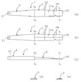
図1は、実施の形態1に係る、インク用へら1の概略全体図の正面図(a)と、裏面図(b)と、側面図(c)と、X0−X0断面図(d)と、X1−X1断面図(e)である。まず、インク用へら1は、持ち手部2と、持ち手部2に接続されたへら部3から構成される。
Embodiments of the present invention will be described with reference to the accompanying drawings.
FIG. 1 is a front view (a), a rear view (b), a side view (c), and a cross-sectional view taken along line X 0 -X 0 (d) of the
持ち手部2は、作業者がインク用へら1を使用する際にこの部位を把持して作業をするためのものであり、長さ100〜150mm、幅が10〜30mm、厚さが10〜20mmの略直方体の棒であり、具体的なサイズは、作業者が取扱い易いものに適宜調整する。本実施の形態1では、長さ130mm、幅は根元(へら部3との境界)付近が28mmであり、先端に近づくつれ細くなり、先端付近が15mmである。また、厚さは15mmに設定された。持ち手部2の素材は、金属、プラスチック、木材など、様々な種類から選択可能である。本実施の形態1では、後述するように、へら部3と同一の素材を用いた。
The handle portion 2 is for an operator to grip and work when using the
持ち手部2の先端近傍には、直径10mmの貫通孔である係合孔21が形成されている。係合孔21は、インク用へら1を使用しないときに、壁や機器などに設置されたフック等に係合するためのものである。
An
へら部3は、持ち手部2に接続され、実際にインクを取り扱う部位である。へら部3は、長さが100mm〜200mm、厚みが0.2〜5mmであり、幅が持ち手部2との境界部分において20mm〜30mmの細長い薄板形状をしており、表面31aと、裏面31bからなる。表面31aは、略平坦な形状をしており、インクを乗せたり撹拌したり等、実際にインクを取り扱うための面である。裏面31bは、図1(c)、(d)、(e)に示すように、へら部3の長辺方向の中心線部から、へら部3の短辺方向のエッジ部32及び長辺方向の先端部33に向けて薄くなるテーパー形状をしている。そして、先端部33のエッジ部32の厚さは0.2〜1.0mmであり、インクを適正に取り扱えるように、使用されるプラスチック材料の曲げ弾性率により適宜設定される。本実施の形態1では、へら部3は長さ140mmである。幅と厚さは、取扱い易くするために、持ち手部2との境界から先端に向かうに従って、細く、薄くなっている。すなわち、幅は持ち手部2との境界近傍で30mm、先端部33近傍で25mm、厚さが持ち手部2との境界近傍で7mm、先端部33近傍で1.5mmと設定した。
The
へら部3の素材は、曲げ弾性率が3〜50トン/cm2の耐印刷インク性のプラスチック系材料である。曲げ弾性率が3トン/cm2以下のプラスチック材料では、へら部3のエッジ部の厚みを0.5mm以上にしないと曲がり易くなり、ソルダーペーストを充分除去できなくなる。また、へら部3の中心線部の厚みを5mm以上に厚くしなければならない。また、曲げ弾性率が50トン/cm2以上のプラスチック材料は硬すぎるので、特にへら部3のエッジ部の厚みが0.2〜0.5mmと薄いためにマスク版に損傷を与えるので好ましくない。
The material of the
曲げ弾性率3〜50トン/cm2で、耐印刷インク性のプラスチック系材料としては、ポリエチレン、ポリプロピレン、4−メチルペンテンー1、ポリオキシメチレン、ポリブチレンテレフタレート、ポリエチレンテレフタレート、ナイロン、ポリウレタン、ポリテトラフルオロエチレン、ポリアセタールが挙げられるが、へら部3と持ち手部2を一体成形する際には、溶融成形可能なポリエチレン、ポリプロピレン、4−メチルペンテンー1、ポリオキシメチレン、ポリブチレンテレフタレート、ポリエチレンテレフタレート、ナイロン、ポリアセタールが実用上好ましい。本実施の形態1では、持ち手部2とへら部3を一体成形するために、ポリプロピレンを用いた。
Examples of plastic materials having a flexural modulus of 3 to 50 ton / cm 2 and a printing ink resistance include polyethylene, polypropylene, 4-methylpentene-1, polyoxymethylene, polybutylene terephthalate, polyethylene terephthalate, nylon, polyurethane, poly Examples include tetrafluoroethylene and polyacetal. When the
さらに、へら部3の成形方法としては、射出成形法、圧縮成形法など、一般に樹脂成形に用いられる方法の他、素材を機械加工して形作る方法、3Dプリンタで形成する方法も使用できる。本実施の形態では、生産性や成形精度を考慮して、射出成形法を用いた。
Further, as a method for forming the
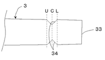
次に、図2に示すように、へら部3の表面31aには、表面31a上に適正にインクを採取するための指標である、インク定量マーク34が1個以上形成されている。本実施の形態1では、インク定量マーク34は、V字状の切欠きで構成し、両側のエッジ部32の向かい合う位置に、1個ずつ形成されている。ここで、図2において、点線U、C、Lは説明の便宜のために図中に記載した仮想の線であり、V字の先端部33側の一端を通る点線Lは、最小ラインを、V字の中心を通る点線Cは目標ラインを、そしてV点の他端を通る線Uは最大ラインを意味する。すなわち、インクを採取するときに、先端部33から点線L乃至Uの間にインクを収めることで、常に一定の範囲内の量のインクを採取することになる。なお、採取されるインクの具体的な量(質量、体積)は、インクの物性(密度や粘度など)により異なってくるので、インク毎に設定をする。なお、物性が近いインクであれば、略同じ質量または体積を採取することになるので、その都度設定する必要はない。
Next, as shown in FIG. 2, one or more ink
インク定量マーク34の位置は、定量採取されるインクの量を決めるものであり、インクの物性と、印刷に必要なインクの量を考慮して、適正な位置に調整される。すなわち、インク定量マーク34が先端部33に近づくほど、採取されるインクは少なくなり、遠ざかるほど多くなる。本実施の形態1では、インクを80g採取するために、インク定量マーク34の中央(点線Cに相当)を、先端部33から40mmの位置に設定した。
The position of the ink
また、インク定量マーク34の大きさは、任意のものに設定可能であるが、へら部3の剛性を保つためには、V字の中心を通る点線C上でのへら部3の幅が、持ち手部2との境界部分における幅の、1/2以上必要である。本実施の形態1では、前者が23mmであり、後者が30mmと設定した。また、V字の両端の間隔(点線UとLの間隔)は10mmに設定した。
The size of the ink fixed
次に、本実施の形態1に係るインク用へら1の作用である、インク用へら1によるインク採取方法について、図3に基づいて説明する。
Next, an ink collection method using the
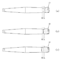
ここでは導電性ペーストPをインク容器から一定量採取する場合について説明する。図3において、(a)の様に導電性ペーストPが点線L、すなわちインク定量マーク34の先端部33側の一端に被らない場合、導電性ペーストPは不足している。また、(b)のように、点線C、すなわちインク定量マーク34の中心近傍にある場合には、導電性ペーストPは適量が採取されていることを意味する。さらに、(c)のように、点線U、すなわちインク定量マーク34の他端側を乗り越えている場合には、導電性ペーストPは過剰に採取されていることを示す。
Here, a case where a certain amount of the conductive paste P is collected from the ink container will be described. In FIG. 3, when the conductive paste P does not cover the dotted line L, that is, one end of the ink fixed
本実施の形態1によれば、へら部3に形成された定量マーク34により、へら部3に乗ったインクの量を把握できるため、印刷版上に適量のインクを供給することが可能となる。
According to the first embodiment, since the amount of ink on the
また、へら部3の素材に一定の曲げ弾性を有する耐印刷インク性のプラスチック系材料を用い、へら部3をブレード状の形状にすることで、効率よくインクをインク容器内で撹拌でき、印刷版に供給・除去することが可能となる。
In addition, by using a printing ink-resistant plastic material having a certain bending elasticity as the material of the
実施の形態2
図4〜図7は、本発明の実施の形態2に係る、インク用へら1のへら部3の主要部を示している。ここで、本実施の形態2の実施の形態1との主な相違点は、インク定量マーク35〜37の形態であるので、これを中心に説明をする。その他、実施の形態1と同様の構成は、図面の符号と説明を省略する。
Embodiment 2
4 to 7 show the main part of the
図4において、インク定量マーク35は、へら部3に対向する配置で形成された、U字状の切欠きであり、実施の形態1と同様に、U字の先端部33側の一端が点線L(最低ライン)、中心が点線C(目標ライン)、他端が点線U(最高ライン)を示している。ここで、インク定量マーク35のサイズと位置は、実施の形態1と同様の方針で設定する。
In FIG. 4, the ink fixed
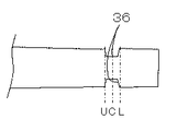
図5において、インク定量マーク36は、へら部3に対向する配置で形成された、コの字状の切欠きであり、実施の形態1と同様に、コの字の先端部33側の一端が点線L(最低ライン)、中心が点線C(目標ライン)、他端が点線U(最高ライン)を示している。ここで、インク定量マーク36のサイズと位置は、実施の形態1と同様の方針で設定する。
In FIG. 5, the ink fixed
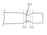
図6において、インク定量マーク37は、へら部3に対向する配置で形成された、図5のコの字を引き延ばした形状である台形状の切欠きである。実施の形態1と同様に、コの字の先端部33側の一端が点線L(最低ライン)、中心が点線C(目標ライン)、他端が点線U(最高ライン)を示している。ここで、インク定量マーク37のサイズと位置は、実施の形態1と同様の方針で設定する。
In FIG. 6, the ink fixed
インク定量マーク37は、実施の形態1とは異なり、最低ラインと最高ラインが2か所備えており、目標ラインを有さない。すなわち、図6においては、持ち手部2側に最高ライン(点線U1)、最低ライン(点線L1)が先端部33側にもう一方の、最高ライン(点線U2)、最低ライン(点線L2)があり、目標ライン(点線C)に相当するものを有さない。
Unlike the first embodiment, the ink fixed
この場合、点線U2とL2に挟まれた領域で第一の定量水準を、U1とL1挟まれた領域で第二の定量水準を形成している。第二の定量水準は、第一の定量水準より多い量のインクを定量することができる。すなわち、図6のインク用へら1は、一個のインク定量マーク37で、2水準の定量をすることが可能である。
In this case, the first quantitative level is formed in the region sandwiched between the dotted lines U2 and L2, and the second quantitative level is formed in the region sandwiched between U1 and L1. The second quantitative level can quantify an amount of ink greater than the first quantitative level. That is, the
図6では、実施の形態1と同様にインク定量マーク37の大きさは、へら部3の剛性を保つために、台形状の切欠きにおけるへら部3の幅が、持ち手部2との境界部分における幅の、1/2以上必要である。図6では、前者が23mmであり、後者が30mmと設定した。また、点線U1とL2の間隔は23mm、U2とL1の間隔は10mmに設定した。
In FIG. 6, as in the first embodiment, the size of the ink
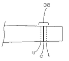
図7において、インク定量用マーク38は、表面31aに形成された刻印である。刻印38は、へら部3のエッジ部の方向(へら部3の短辺方向)に向いた二本以上の線で構成される。図7では3本の線で形成した。
In FIG. 7, the
ここで、最低ライン、目標ライン、最高ラインはそれぞれこれまでの実施の形態と異なり、実際にへら部3上に形成されているものである。そこで、ここでは線U、線C、線Lと呼称する。
Here, the lowest line, the target line, and the highest line are actually formed on the
また、識別の便宜のために、線Uと線Lは破線で、線Cは実線で形成した。もちろん、これ以外の組み合わせや線種を用いても良い。線の太さと深さまたは高さは視認性と取扱い性を考えて0.2〜1mmが好ましい。0.2mmより細い(浅い)と、視認が困難であり、1mmより太い(深い)と、インクが線に引っかかり、除去しづらくなり、取扱い性を損なう。図7においては、太さと深さを0.5mmに設定した。 For convenience of identification, the lines U and L are formed by broken lines, and the line C is formed by a solid line. Of course, other combinations and line types may be used. The thickness, depth, or height of the line is preferably 0.2 to 1 mm in view of visibility and handleability. If it is thinner (shallow) than 0.2 mm, it is difficult to visually recognize it. If it is thicker (deep) than 1 mm, the ink will be caught by the line and it will be difficult to remove, and the handling will be impaired. In FIG. 7, the thickness and depth were set to 0.5 mm.
本実施の形態2によれば、へら部3に形成された定量マーク35〜38により、へら部3に乗ったインクの量を把握できるため、印刷版上に適量のインクを供給することが可能となる。
According to the second embodiment, since the amount of ink on the
また、へら部3の素材に一定の曲げ弾性を有する耐印刷インク性のプラスチック系材料を用い、へら部3をブレード状の形状にすることで、効率よくインクをインク容器内で撹拌でき、印刷版に供給・除去することが可能となる。
In addition, by using a printing ink-resistant plastic material having a certain bending elasticity as the material of the
実施の形態3
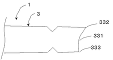
図8は、本発明の実施の形態3に係る、インク用へら1のへら部3の主要部を示している。ここで、本実施の形態3の実施の形態1との主な相違点は、先端部33の形状であるので、これを中心に説明をする。その他、実施の形態1と同様の構成は、図面の符号と説明を省略する。
FIG. 8 shows the main part of the
本実施の形態3において、へら部3の先端部33には、持ち手部2側に向かってカーブした円弧状の切欠き331が形成されており、先端部33二股に分かれた形態をしている。この切欠き331は、インク容器Cの底の形状にフィットするように形成されている。
In the third embodiment, the
次に、本実施の形態3に係るインク用へら1の作用である、インク用へら1によるインク採取方法について、図9に基づいて説明する。
Next, an ink collection method using the
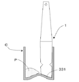
図9は、インク容器Cにインク用へら1を挿入している状態の、概略内部構成であり、容器の底に導電性ペーストPが少量残存している。
FIG. 9 shows a schematic internal configuration in a state where the
また、インク容器Cの底は中央に向かって凸型に盛り上がっている。 Further, the bottom of the ink container C is raised in a convex shape toward the center.
本実施の形態3に係るインク用へら1は、先端部33が円弧状の切欠き331を有するので、先端部33をインク容器Cの底当接したとき、底にフィットすることができる。
In the
インク用へら1を、インク容器Cの底と側壁に押し当てながら、インク容器C内を摺動させることで、底に残った導電性ペーストPを有効に採取する。
By sliding the
本実施の形態3によれば、へら部3の先端部33の円弧状の切欠き331により先端部が二股に分かれているため、先端部33が、底が凸型に盛り上がったインク容器Cの底と線状に接触するため、インク容器Cの導電性ペーストPを効率よく採取することが可能となる。
According to the third embodiment, since the tip portion is divided into two forks by the arc-shaped
以上、実施の形態1〜3について説明したが、本発明はこれに限られるものではない。例えば、上記実施の形態では、インク定量マーク34〜38はエッジ部32の両側に1個ずつ設けたが、これは片側1個だけでも良ければ、片側または両側2個以上設けても良いし。ここで、エッジ部32の片側または両側に2個以上設けられた場合は、1本のインク用へら1で、インク定量できる水準を増やすことが可能となる。
While the first to third embodiments have been described above, the present invention is not limited to this. For example, in the above-described embodiment, one ink fixed
また、1本のインク用へら1に、異なる形態のインク定量マーク34〜38を設けても良い。
In addition, different amounts of ink
また、図6のインク定量マーク37の場合において、U1とL1、U2とL2の間に、インク定量マーク38のCのような刻印を設けて、目標ラインを視覚化してもよい。
In the case of the ink fixed
さらに、実施の形態3には、刻印38は線に限られるものではなく、例えば記号や数字、文字など、視認性のあるものであれば、他の形態をとることが可能である。また、凸形状であってもよい。 Further, in the third embodiment, the marking 38 is not limited to a line, and may take other forms as long as it has visibility such as symbols, numbers, and characters. Moreover, a convex shape may be sufficient.
1 インク用へら
2 持ち手部
3 へら部
31a 表面
31b 裏面
32 エッジ部
33 先端部
331 切欠き
34、35、36、37、38 インク定量マーク
DESCRIPTION OF
Claims (5)
長さが100mm〜150mmである棒状の持ち手部と、
前記持ち手部に接続され、長さが100mm〜200mm、厚みが0.2〜5mmであり、幅が前記持ち手部との境界部分において20mm〜30mmの細長い薄板形状のへら部と、を備え、
前記へら部は、1個以上のインク定量用マークを有する、
ことを特徴とするインク用へら。 A spatula for ink used for screen printing,
A rod-shaped handle having a length of 100 mm to 150 mm;
An elongated thin plate-like spatula portion connected to the handle portion, having a length of 100 mm to 200 mm, a thickness of 0.2 to 5 mm, and a width of 20 mm to 30 mm at a boundary portion with the handle portion. ,
The spatula portion has one or more ink quantitative marks,
Spatula for ink characterized by that.
ことを特徴とする請求項1に記載のインク用へら。 The spatula portion is made of a printing ink-resistant plastic material having a flexural modulus of 3 to 50 ton / cm 2 , and has a substantially flat surface and a center line portion in the long side direction of the spatula portion. It consists of a back surface having a tapered shape that becomes thinner toward the front end portion in the long side direction and the edge portion in the short side direction, and the thickness of the front end portion and the edge portion is 0.2 to 0.5 mm.
The spatula for ink according to claim 1.
該切欠きにおける前記へら部の幅は、前記持ち手部との境界部分における幅の1/2以上である、
ことを特徴とする、請求項1または2のいずれか1項に記載のインク用へら。 At least one of the ink determination marks is a V-shaped, U-shaped or U-shaped notch,
The width of the spatula portion in the notch is 1/2 or more of the width in the boundary portion with the handle portion,
The ink spatula according to claim 1, wherein the spatula for ink is used.
ことを特徴とする、請求項1から3のいずれか1項に記載のインク用へら。 At least one or more of the ink quantification marks is a mark formed on the surface, and the mark is composed of two or more lines facing the edge portion of the spatula portion.
The ink spatula according to any one of claims 1 to 3, wherein the spatula for ink is used.
ことを特徴とする、請求項1から4のいずれか1項に記載のインク用へら。
The tip of the spatula has an arc-shaped notch that is curved toward the handle portion side,
The ink spatula according to any one of claims 1 to 4, wherein the spatula for ink is used.
Priority Applications (1)
| Application Number | Priority Date | Filing Date | Title |
|---|---|---|---|
| JP2016040150A JP6405548B2 (en) | 2016-03-02 | 2016-03-02 | Spatula for ink |
Applications Claiming Priority (1)
| Application Number | Priority Date | Filing Date | Title |
|---|---|---|---|
| JP2016040150A JP6405548B2 (en) | 2016-03-02 | 2016-03-02 | Spatula for ink |
Publications (2)
| Publication Number | Publication Date |
|---|---|
| JP2017154392A true JP2017154392A (en) | 2017-09-07 |
| JP6405548B2 JP6405548B2 (en) | 2018-10-17 |
Family
ID=59808645
Family Applications (1)
| Application Number | Title | Priority Date | Filing Date |
|---|---|---|---|
| JP2016040150A Active JP6405548B2 (en) | 2016-03-02 | 2016-03-02 | Spatula for ink |
Country Status (1)
| Country | Link |
|---|---|
| JP (1) | JP6405548B2 (en) |
Cited By (1)
| Publication number | Priority date | Publication date | Assignee | Title |
|---|---|---|---|---|
| WO2019031584A1 (en) | 2017-08-09 | 2019-02-14 | 国立研究開発法人科学技術振興機構 | Measurement device and irradiation device |
Citations (5)
| Publication number | Priority date | Publication date | Assignee | Title |
|---|---|---|---|---|
| JPH0294560U (en) * | 1988-09-07 | 1990-07-27 | ||
| JP2000225687A (en) * | 1999-02-08 | 2000-08-15 | Process Lab Micron:Kk | Soft spatula |
| JP3167367U (en) * | 2010-12-15 | 2011-04-21 | 井上工具株式会社 | Spatula |
| JP3195010U (en) * | 2014-08-27 | 2014-12-25 | 井上工具株式会社 | Spatula |
| JP2015150503A (en) * | 2014-02-14 | 2015-08-24 | 大志 金原 | Putty spatula |
-
2016
- 2016-03-02 JP JP2016040150A patent/JP6405548B2/en active Active
Patent Citations (5)
| Publication number | Priority date | Publication date | Assignee | Title |
|---|---|---|---|---|
| JPH0294560U (en) * | 1988-09-07 | 1990-07-27 | ||
| JP2000225687A (en) * | 1999-02-08 | 2000-08-15 | Process Lab Micron:Kk | Soft spatula |
| JP3167367U (en) * | 2010-12-15 | 2011-04-21 | 井上工具株式会社 | Spatula |
| JP2015150503A (en) * | 2014-02-14 | 2015-08-24 | 大志 金原 | Putty spatula |
| JP3195010U (en) * | 2014-08-27 | 2014-12-25 | 井上工具株式会社 | Spatula |
Cited By (1)
| Publication number | Priority date | Publication date | Assignee | Title |
|---|---|---|---|---|
| WO2019031584A1 (en) | 2017-08-09 | 2019-02-14 | 国立研究開発法人科学技術振興機構 | Measurement device and irradiation device |
Also Published As
| Publication number | Publication date |
|---|---|
| JP6405548B2 (en) | 2018-10-17 |
Similar Documents
| Publication | Publication Date | Title |
|---|---|---|
| JP6405548B2 (en) | Spatula for ink | |
| SE510370C2 (en) | Tool for mechanical sealing of hollow hoses of flexible material | |
| US6434838B1 (en) | Protective sheath for saw teeth of a handsaw | |
| US7603740B2 (en) | Spatula for cleaning cylindrical containers | |
| US7788760B2 (en) | Transfer tool | |
| SE511864C2 (en) | Spatula for sampling including perforations | |
| US4115892A (en) | Scraping tool | |
| CN106475347A (en) | A kind of ink puddler cleaning device | |
| US889004A (en) | Envelop-opener. | |
| CN201776979U (en) | Printing ink scraping brush | |
| JP2005338058A (en) | Oil level gage | |
| EP0992354A3 (en) | Cleaning fluid for inkjet printers | |
| JP2009226672A (en) | Fluid jetting apparatus | |
| JP2006234408A (en) | Measuring spoon | |
| JP2012163542A (en) | Measuring spoon | |
| CN106999877B (en) | Stirring paddle | |
| JP2015150503A (en) | Putty spatula | |
| US233202A (en) | Butter-trier | |
| CN213973210U (en) | Cleaning device for printer | |
| JP3081560U (en) | Eraser | |
| JP4505744B2 (en) | Mayonnaise scraped stick | |
| CN106958342A (en) | A kind of conductive primary coat construction trowel | |
| US1696076A (en) | Combination implement | |
| JP7351208B2 (en) | measuring spoon | |
| JP7327797B2 (en) | Molding sand raking tool and molding sand raking tool set |
Legal Events
| Date | Code | Title | Description |
|---|---|---|---|
| A621 | Written request for application examination |
Free format text: JAPANESE INTERMEDIATE CODE: A621 Effective date: 20180328 |
|
| A871 | Explanation of circumstances concerning accelerated examination |
Free format text: JAPANESE INTERMEDIATE CODE: A871 Effective date: 20180328 |
|
| A975 | Report on accelerated examination |
Free format text: JAPANESE INTERMEDIATE CODE: A971005 Effective date: 20180524 |
|
| A131 | Notification of reasons for refusal |
Free format text: JAPANESE INTERMEDIATE CODE: A131 Effective date: 20180530 |
|
| A521 | Request for written amendment filed |
Free format text: JAPANESE INTERMEDIATE CODE: A523 Effective date: 20180719 |
|
| TRDD | Decision of grant or rejection written | ||
| A01 | Written decision to grant a patent or to grant a registration (utility model) |
Free format text: JAPANESE INTERMEDIATE CODE: A01 Effective date: 20180821 |
|
| A61 | First payment of annual fees (during grant procedure) |
Free format text: JAPANESE INTERMEDIATE CODE: A61 Effective date: 20180822 |
|
| R150 | Certificate of patent or registration of utility model |
Ref document number: 6405548 Country of ref document: JP Free format text: JAPANESE INTERMEDIATE CODE: R150 |
|
| R250 | Receipt of annual fees |
Free format text: JAPANESE INTERMEDIATE CODE: R250 |
|
| R250 | Receipt of annual fees |
Free format text: JAPANESE INTERMEDIATE CODE: R250 |
|
| R250 | Receipt of annual fees |
Free format text: JAPANESE INTERMEDIATE CODE: R250 |
|
| R250 | Receipt of annual fees |
Free format text: JAPANESE INTERMEDIATE CODE: R250 |
|
| R250 | Receipt of annual fees |
Free format text: JAPANESE INTERMEDIATE CODE: R250 |