JP2017152909A - Monitoring camera system - Google Patents
Monitoring camera system Download PDFInfo
- Publication number
- JP2017152909A JP2017152909A JP2016033302A JP2016033302A JP2017152909A JP 2017152909 A JP2017152909 A JP 2017152909A JP 2016033302 A JP2016033302 A JP 2016033302A JP 2016033302 A JP2016033302 A JP 2016033302A JP 2017152909 A JP2017152909 A JP 2017152909A
- Authority
- JP
- Japan
- Prior art keywords
- monitoring
- surveillance camera
- camera
- camera system
- battery
- Prior art date
- Legal status (The legal status is an assumption and is not a legal conclusion. Google has not performed a legal analysis and makes no representation as to the accuracy of the status listed.)
- Pending
Links
Images

Landscapes
- Closed-Circuit Television Systems (AREA)
- Studio Devices (AREA)
Abstract
Description
本発明は、建設現場、解体現場、資材置場、畜産現場、農場等の電力の供給が困難な場所において使用する監視カメラシステムに関するものである。 The present invention relates to a surveillance camera system used in places where it is difficult to supply electric power, such as construction sites, dismantling sites, material storage sites, livestock production sites, and farms.
従来、建設現場、解体現場、資材置場等においては、高価な重機や資材、又はビル等の解体時に集積されるスクラップ材の盗難対策として、監視カメラを設置し、現場を撮影することが行われている。同様に、畜産現場、農場等においても、家畜や農産物等の盗難対策、野生動物による食害対策として、監視カメラを設置し現場を監視することが行われている。 Conventionally, at construction sites, demolition sites, materials storage, etc., as a countermeasure against theft of expensive heavy machinery and materials, or scrap materials accumulated at the time of demolition of buildings, etc., surveillance cameras have been set up and filmed at the site ing. Similarly, in livestock production sites and farms, monitoring cameras are installed by monitoring cameras as a countermeasure against theft of livestock and agricultural products and as a countermeasure against food damage caused by wild animals.
昼夜別なく常時、監視カメラを作動するためには、バッテリではなく商用電源から電力供給を行う必要がある。 In order to always operate the surveillance camera day and night, it is necessary to supply power from a commercial power supply instead of a battery.
しかし、建設現場、解体現場、工事現場、資材置場、畜産現場、農場等の作業現場においては、必ずしも商用電源が常時供給されているとは限らない。例えば、ビル等の解体現場においては、安全面の問題等から商用電源の契約を解除した上で解体作業を行っている。このような場合には、商用電源を利用した監視カメラによって常時、作業現場を監視を行うことができないという問題が発生する。 However, commercial power is not always supplied at work sites such as construction sites, demolition sites, construction sites, material storage sites, livestock sites, and farms. For example, in a demolition site such as a building, the demolition work is performed after canceling the contract of the commercial power supply due to safety problems. In such a case, there arises a problem that the work site cannot always be monitored by a monitoring camera using a commercial power source.
また、単なる資材置場や農場においては、元々商用電源が敷設されていない場合も多い。広大な資材置場や農場を監視するためには、商業電源を電源ケーブルにより長い距離を引き込む必要があり、コスト的負担が極めて大きい。 In addition, there are many cases where commercial power sources are not originally laid in simple material storage areas or farms. In order to monitor vast material storage and farms, it is necessary to draw a commercial power source over a long distance with a power cable, which is extremely costly.
また、農場等の監視においては、常時、広大な農場全体をくまなく監視するのではなく、野生動物による食害が発生した際に、野生動物の侵入経路や食害エリアを監視したり、或いは収穫期にのみ監視できるように、監視カメラの移動・設置・撤去等を簡便にできることも求められている。 In addition, when monitoring farms, etc., the entire vast farm is not always monitored, but when wild animals cause food damage, the path of wild animals and the damage area are monitored, or the harvest period It is also required that the surveillance camera can be easily moved, installed, removed, etc. so that it can only be monitored.
同様に、建設現場、解体現場、工事現場等の現場においても、監視期間は一時的であるため、監視カメラの移動・設置・撤去等を簡便にできることも求められている。 Similarly, at the construction site, the demolition site, the construction site, and the like, since the monitoring period is temporary, it is required that the monitoring camera can be easily moved, installed, removed, and the like.
本発明の目的は、上述の課題を解消し、商用電源が使用できない現場においても監視が可能であって、現場機器の移動・設置・撤去等を簡便にできる監視カメラシステムを提供することにある。 An object of the present invention is to provide a surveillance camera system that solves the above-described problems, can be monitored even in a site where a commercial power source cannot be used, and can easily move, install, and remove field devices. .
上記目的を達成するための本発明に係る監視カメラシステムは、現場に設置する現場機器と、該現場機器と無線ネットワーク網を介して接続した中央監視装置とから成る監視カメラシステムであって、前記現場機器は、バッテリ及び該バッテリに接続した発電装置から成るカメラ接続機器と、前記バッテリに接続する1個又は複数個の監視カメラとから構成したことを特徴とする。 In order to achieve the above object, a surveillance camera system according to the present invention is a surveillance camera system comprising a field device installed in a field, and a central monitoring device connected to the field device via a wireless network, The field device includes a camera connection device including a battery and a power generation device connected to the battery, and one or a plurality of monitoring cameras connected to the battery.
本発明に係る監視カメラシステムによれば、電源自給型の監視カメラを用いることで、商用電源が使用できない現場を監視することができ、監視カメラを含む現場機器を使用目的・個所に応じて、簡便に設置可能である。 According to the surveillance camera system of the present invention, by using a self-powered surveillance camera, it is possible to monitor a site where commercial power cannot be used, and depending on the purpose and location of the field equipment including the surveillance camera, It can be installed easily.
本発明を図示の実施例に基づいて詳細に説明する。 The present invention will be described in detail based on the embodiments shown in the drawings.
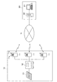
図1は本実施例1における監視カメラシステムのブロック図である。この監視カメラシステムは、建設現場、解体現場、工事現場等の作業現場に配置する現場機器10と、携帯通信網等の無線ネットワーク網Nを介して、現場機器10と接続し、監視センタ等に設置する中央監視装置20とから構成されている。
FIG. 1 is a block diagram of the surveillance camera system according to the first embodiment. This surveillance camera system is connected to a
現場機器10は、資材やスクラップ材を監視する単色又はカラー用の少なくとも1台の監視カメラ11を有し、各監視カメラ11には共用のバッテリ12を介して1個の太陽電池パネル13が接続されている。
The
バッテリ12及び太陽電池パネル13から成るカメラ接続機器は、太陽電池パネル13に代えて、燃料を利用した発電機等の適宜の自給式発電装置をバッテリ12に接続するようにしてもよい。
The camera connection device including the
このように電源自給型の監視カメラ11は、CCD型等の撮像素子及び撮影レンズから成る撮像部11aを備え、この撮像部11aはカメラ11内の無線通信部11bに接続されている。また、監視カメラ11に例えば撮像部11aが透明のドーム状の樹脂製フード体により覆われた防水構造を採用することができる。
Thus, the self-powered
監視センタに設置する中央監視装置20は、監視端末21と、この監視端末21に接続する監視サーバ22とから構成されている。監視端末21はモニタ、キーボード及びマウス等から構成され、監視員がモニタを見ながら監視カメラ1に対する各種の操作を行うようになっている。
The
図1においては、バッテリ12と太陽電池パネル13の1組に対して、3台の監視カメラ11が接続されているが、監視カメラ1同士が離れている場合等においては、複数組のバッテリ12と太陽電池パネル13とを用意し、それぞれに単体又は複数台の監視カメラ11を接続するようにしてもよい。
In FIG. 1, three
監視カメラ11と接続するバッテリ12は、昼間は太陽電池パネル13からの出力により充電をすると共に、監視カメラ11に電力を供給している。夜間になると、昼間に充電した電力によって、バッテリ12から監視カメラ11に電力を供給する。
The
監視カメラ11とバッテリ12と太陽電池パネル13は、1つの架台に取り付けるようにしてもよく、このような場合に、架台の移動を容易にするキャスタを架台に取り付けることが好ましい。この架台は組立式とし、分解して、監視カメラ11とバッテリ12と太陽電池パネル13とを個々に撤去することが可能である。
The
また、1組のバッテリ12と太陽電池パネル13とに対して、図示するように複数個の監視カメラ11を接続する場合には、電源用延長ケーブルを敷設することで、複数個の監視カメラ11を用いて広範囲な監視を行うことが可能となる。
In addition, when a plurality of
監視カメラ11の撮像部11aによって撮像された映像は、無線通信部11bのアンテナからインタネット等のネットワーク網Nを介して、中央監視装置20に送信される。
The video imaged by the
中央監視装置20の監視端末21からネットワーク網Nを介する遠隔操作により、監視カメラ11は撮像部11aのズーミングやパンニングを操作する機能を備えている。例えば、監視カメラ11の映像を監視している監視センタにおいて、監視員が不審者が侵入したことを察知した場合には、その不審者に向けて撮像部11aをズーミングし、不審者の顔等を鮮明に映し出すことが可能である。
The
また、監視カメラ11はマイクロホンやスピーカを内蔵しており、必要に応じてマイクロホンを介して作業現場の音声を収集したり、スピーカを介して音声による注意喚起や警告音等を出力することができる。更に、監視カメラ11の撮像部11aは赤外線カメラモードを備えるようにしてもよく、赤外線カメラモードに切換えることで、夜間でも赤外線を用いた撮像により鮮明に映像を映し出すことができる。
Moreover, the
また、監視カメラ11には、人間や動物等の動く物体に反応する近赤外線や超音波を利用した人感センサが反応した場合に、中央監視装置20から必要に応じた緊急通知処理を行えばよい。或いは、人感センサが反応した際に監視カメラ11による撮像を開始したり、それまでの間欠的な撮像を連続的な撮像に切換えて、監視端末21に表示させる。このようにすることで、夜間におけるバッテリ12の電力消費を抑えることができる。
Further, when a human sensor using near infrared rays or ultrasonic waves that reacts to a moving object such as a human being or an animal reacts with the
また、外部からネットワーク網Nを介して、バッテリ12のバッテリ残量を把握することもできる。仮に、バッテリ12のバッテリ残量が少ないと判明した場合には、監視カメラ11の撮影モードを節電モードとすることもできる。この節電モードでは、リアルタイムで映像を送信する通常モードに代えて、例えば映像を所定時間間隔で中央監視装置20に送信することで、消費電力を節約できる。
Further, the remaining battery level of the
監視端末21のモニタには、作業現場に配置した複数個の監視カメラ11からリアルタイムで送信される映像を、監視端末21のモニタ画面上の小区画にそれぞれ同時に表示させることが可能である。監視員は小区画の映像を拡大表示したり、監視カメラ11に対してズーミングやパンニング、音声出力等の遠隔操作を適宜に実施することが可能である。また、モニタ画面には監視カメラ11毎の画像をに所定の時間間隔で切換えながら表示することもできる。
On the monitor of the
監視サーバ22は有線によりネットワーク網Nと接続されており、監視カメラ11からインタネット等のネットワーク網Nを介して送信されるリアルタイムの映像を監視サーバ22内のハードディスク等の記録媒体に記録してゆく。
The
これらの記録された映像は、記録媒体に保存後に、所定期間が経過すると新しく送信された撮影データを上書きすることにより更新される。なお、監視カメラ11の撮影映像は、監視カメラ11本体に内蔵した記憶媒体にも一定期間、記憶することもできる。
These recorded videos are updated by overwriting newly transmitted shooting data after a predetermined period of time has elapsed after being stored in the recording medium. Note that the video captured by the
監視センタの監視員は、昼間は作業現場の作業員が安全に作業をしているか、又は作業の進捗状況を監視している。そして、夜間になると、作業員がいない作業現場において、重機、資材やスクラップ材の盗難を監視することになる。 The supervisor at the monitoring center monitors whether the workers at the work site are working safely during the day or the progress of the work. At night, theft of heavy machinery, materials and scrap materials is monitored at work sites where there are no workers.
夜間では、監視カメラ11を通常モードから前述の赤外線カメラモードに切換え、併せて人感センサを起動することで、複数個の監視カメラ11の映像の中から、人感センサが反応した監視カメラ11の映像を優先的に監視端末21に拡大表示したり、別途に人感カメラからの通知を受けることもできる。
At night, the
なお、監視カメラ11の昼間と夜間の切換えはタイマを用いてもよく、或いは照度センサを用いて昼夜の区別により切換えるようにしてもよい。これらのタイマや照度センサは監視カメラ11本体に内蔵させることが好ましい。
Note that the
また、夜間での撮像は主として防犯用のためであるので、監視カメラ11は広い範囲を水平方向にパンニングすることを繰り返し、人感センサによって動く物体を検知すると監視カメラ11をその方向に固定し撮影を続け、必要に応じてズーミングを行うことが考えられる。そして、物体の動きがなくなれば再びパンニングを繰り返せばよい。
Also, since nighttime imaging is mainly for crime prevention, the
更に、昼間と夜間では、現場機器10の配置位置を変更することもできる。例えば、昼間では主に作業を行う作業員を監視できる場所に現場機器10を設置させ、夜間では車両の出入口や資材置場を監視できる場所に移動させることも好適である。
Furthermore, the arrangement position of the
図1のブロック図では、1個所の作業現場に対して、1個の中央監視装置20を用いることを説明した。図2は実施例2のブロック図を示し、複数の作業現場の現場機器10に対して、1個の中央監視装置20で運用することを可能としている。なお、実施例1と同様の部材には同一の符号を付している。
In the block diagram of FIG. 1, it has been described that one
また、各監視カメラ11の映像を集約して管理する監視サーバ22に対して、携帯電話等の移動端末30や作業現場に配置したノートパソコン等の操作端末14からアクセスして、監視カメラ11の撮影映像を確認することも可能である。
In addition, the monitoring
このような場合には、監視サーバ22には各接続端末に対して、ユーザIDとパスワードを設定し、ユーザIDとパスワードとが一致した接続端末のみに対してアクセスを許可し、監視カメラ11の映像を送信することになる。
In such a case, the monitoring
移動端末30はどの個所からでも、任意の監視カメラ11の映像を確認することができ、作業現場で異変が発生した場合に、作業現場に向う途中の監視員に作業現場の状況をリアルタイムで確認することができる。
The
また、作業現場で作業を監督する監督員は、仮事務所等に設けたノートパソコンやタブレットPC等の操作端末14を用いて、現場の作業員が安全に作業をしているか、又は作業の進捗状況を把握することが可能である。
In addition, the supervisor who supervises the work at the work site uses the
実施例1、2における監視カメラシステムは、商用電源又は光ファイバ等の通信回線を敷設していない現場や、敷設困難な現場等においても、現場機器10を配置することで、簡便に監視システムを構築することができる。また、現場機器10の撤去も簡便に行うことができる。
In the surveillance camera system in the first and second embodiments, the
このような監視カメラシステムを設けることにより、監視カメラ11で撮影した映像を無線ネットワーク網Nを介して遠隔地にリアルタイムで送信でき、重機、備品、資材、家畜、農産物の盗難を防止したり、野生動物による食害の監視、不審者の侵入を監視することができる。
By providing such a surveillance camera system, video taken by the
10 現場機器
11 監視カメラ
11a 撮像部
11b 無線通信部
12 バッテリ
13 太陽電池パネル
14 操作端末
20 中央監視装置
21 監視端末
22 監視サーバ
30 移動端末
DESCRIPTION OF
Claims (7)
前記現場機器は、バッテリ及び該バッテリに接続した発電装置から成るカメラ接続機器と、前記バッテリに接続する1個又は複数個の監視カメラとから構成したことを特徴とする監視カメラシステム。 A surveillance camera system comprising a field device installed in a field and a central monitoring device connected to the field device via a wireless network;
The on-site device comprises a camera connection device comprising a battery and a power generation device connected to the battery, and one or a plurality of monitoring cameras connected to the battery.
Priority Applications (1)
| Application Number | Priority Date | Filing Date | Title |
|---|---|---|---|
| JP2016033302A JP2017152909A (en) | 2016-02-24 | 2016-02-24 | Monitoring camera system |
Applications Claiming Priority (1)
| Application Number | Priority Date | Filing Date | Title |
|---|---|---|---|
| JP2016033302A JP2017152909A (en) | 2016-02-24 | 2016-02-24 | Monitoring camera system |
Publications (1)
| Publication Number | Publication Date |
|---|---|
| JP2017152909A true JP2017152909A (en) | 2017-08-31 |
Family
ID=59740938
Family Applications (1)
| Application Number | Title | Priority Date | Filing Date |
|---|---|---|---|
| JP2016033302A Pending JP2017152909A (en) | 2016-02-24 | 2016-02-24 | Monitoring camera system |
Country Status (1)
| Country | Link |
|---|---|
| JP (1) | JP2017152909A (en) |
Cited By (4)
| Publication number | Priority date | Publication date | Assignee | Title |
|---|---|---|---|---|
| CN107592501A (en) * | 2017-09-19 | 2018-01-16 | 成都金雅图科技有限公司 | Acquisition system and method for farming activities process data |
| CN108833844A (en) * | 2018-06-29 | 2018-11-16 | 安徽香妃茶业有限公司 | A kind of solar energy monitor |
| WO2019198436A1 (en) * | 2018-04-10 | 2019-10-17 | 株式会社クボタ | Work machine monitoring system |
| KR102648016B1 (en) * | 2023-07-25 | 2024-03-18 | 주식회사 유클리드소프트 | Solar cell based low-power intelligent waste dumping detection system and method |
-
2016
- 2016-02-24 JP JP2016033302A patent/JP2017152909A/en active Pending
Cited By (6)
| Publication number | Priority date | Publication date | Assignee | Title |
|---|---|---|---|---|
| CN107592501A (en) * | 2017-09-19 | 2018-01-16 | 成都金雅图科技有限公司 | Acquisition system and method for farming activities process data |
| WO2019198436A1 (en) * | 2018-04-10 | 2019-10-17 | 株式会社クボタ | Work machine monitoring system |
| JP2019182212A (en) * | 2018-04-10 | 2019-10-24 | 株式会社クボタ | Monitoring system for work machine |
| US11954947B2 (en) | 2018-04-10 | 2024-04-09 | Kubota Corporation | Monitoring system for working machine |
| CN108833844A (en) * | 2018-06-29 | 2018-11-16 | 安徽香妃茶业有限公司 | A kind of solar energy monitor |
| KR102648016B1 (en) * | 2023-07-25 | 2024-03-18 | 주식회사 유클리드소프트 | Solar cell based low-power intelligent waste dumping detection system and method |
Similar Documents
| Publication | Publication Date | Title |
|---|---|---|
| CN206932333U (en) | Power grid visualization intelligent monitoring administration plateform system | |
| US10392829B2 (en) | Smart fence | |
| KR101565134B1 (en) | Wild animals extermination system | |
| US20090122143A1 (en) | Security system and network | |
| KR101178927B1 (en) | Remote fire protection system | |
| JP2017152909A (en) | Monitoring camera system | |
| KR101381924B1 (en) | System and method for monitoring security using camera monitoring apparatus | |
| JP3204442U (en) | Surveillance camera system | |
| KR102124594B1 (en) | Intense Heat and Cold Wave Alert System Using CCTV Emergency Bell Network | |
| KR100771985B1 (en) | Movable and installable type control tower | |
| KR101483949B1 (en) | Total mornitoring system | |
| CN202771568U (en) | Infrared detection alarm all-in-one machine with remote alarm function | |
| JP2009015536A (en) | Suspicious person report device, suspicious person monitoring device and remote monitoring system using the same | |
| CN102184602A (en) | Bank automatic teller machine (ATM) and field facility narrow-band monitoring and warning system | |
| JP3185350U (en) | Remote monitoring device | |
| JP2001069268A (en) | Communication equipment | |
| KR101281494B1 (en) | An auto control system of intelligent ptz camera using smart phone | |
| KR101594053B1 (en) | Security System Through Convergence Solutions | |
| JP2017173998A (en) | Security system | |
| JP2011164768A (en) | Security system | |
| JP2017175184A (en) | Monitoring camera system | |
| KR20160104332A (en) | A system for providing notification service for emergency using imaging apparatus and a method for the same | |
| KR101416076B1 (en) | Cctv emergency call system | |
| KR100977537B1 (en) | All in one type DVR having homenetwork system | |
| KR20220128166A (en) | Construction site smart vehicle with smart safety mobile camera |