JP2017149115A - Ink roller and printer - Google Patents
Ink roller and printer Download PDFInfo
- Publication number
- JP2017149115A JP2017149115A JP2016035970A JP2016035970A JP2017149115A JP 2017149115 A JP2017149115 A JP 2017149115A JP 2016035970 A JP2016035970 A JP 2016035970A JP 2016035970 A JP2016035970 A JP 2016035970A JP 2017149115 A JP2017149115 A JP 2017149115A
- Authority
- JP
- Japan
- Prior art keywords
- ink
- ink roller
- rollers
- printing
- tube
- Prior art date
- Legal status (The legal status is an assumption and is not a legal conclusion. Google has not performed a legal analysis and makes no representation as to the accuracy of the status listed.)
- Granted
Links
Images


Landscapes
- Rotary Presses (AREA)
- Inking, Control Or Cleaning Of Printing Machines (AREA)
Abstract
Description
本発明は、刷版を用いて印刷を行うオフセット輪転印刷機において、インキを転写するインキローラ及び印刷機に関するものである。 The present invention relates to an ink roller and a printing press for transferring ink in an offset rotary printing press that performs printing using a printing plate.
例えば、新聞用オフセット輪転印刷機は、給紙装置と印刷装置とウェブパス装置と折機とから構成されている。そして、印刷装置は、複数の印刷ユニットを有し、各印刷ユニットは、対応するウェブに対して印刷を行う。そして、印刷ユニットは、インキ供給源と、複数のローラを用いてインキを供給するインキ供給装置と、刷版が装着された版胴と、インキ(画像)を印刷紙に転写するフランケット胴を有している。 For example, an offset rotary printing press for newspapers includes a paper feeding device, a printing device, a web pass device, and a folding machine. The printing apparatus includes a plurality of printing units, and each printing unit performs printing on a corresponding web. The printing unit includes an ink supply source, an ink supply device that supplies ink using a plurality of rollers, a plate cylinder on which a printing plate is mounted, and a flanket cylinder that transfers ink (image) to printing paper. Have.
印刷ユニットにて、インキ供給装置は、表面にゴム層を有する複数のインキローラを備えており、このインキローラは、金属製の円筒管の表面にゴムが巻き付けられたゴムローラとして構成されている。このようなインキローラとして、例えば、下記特許文献1に記載されたものがある。 In the printing unit, the ink supply device includes a plurality of ink rollers having a rubber layer on the surface, and the ink roller is configured as a rubber roller in which rubber is wound around the surface of a metal cylindrical tube. An example of such an ink roller is described in Patent Document 1 below.
鉄鋼材料である厚肉鋼管を使用しており、剛性が高いものの重量物であることから慣性力も大きい。そのため、鋼管の外周面を研削加工して外径を小さくする必要がある。また、インキローラが高速回転して使用することから、鋼管の内周面を偏肉加工する必要があり、高度な加工技術が必要となる。そのため、従来のインキローラは、製造コストが増加すると共に、重量物であって取扱性がよくないという問題がある。 A thick steel pipe, which is a steel material, is used, and the inertial force is large because it is heavy but heavy. Therefore, it is necessary to grind the outer peripheral surface of the steel pipe to reduce the outer diameter. Further, since the ink roller is rotated at a high speed, the inner peripheral surface of the steel pipe needs to be unevenly machined, and a high-level processing technique is required. Therefore, the conventional ink roller has a problem that the manufacturing cost is increased and the handling property is not good because it is heavy.
本発明は、上述した課題を解決するものであり、製造コストを低減すると共に軽量化を図るインキローラ及び印刷機を提供することを目的とする。 SUMMARY An advantage of some aspects of the invention is to provide an ink roller and a printing machine that reduce the manufacturing cost and reduce the weight.
上述の目的を達成するための本発明のインキローラは、周方向の一部に継ぎ目部を有する金属製のシームド管と、前記シームド管の外周面に形成された弾性層と、前記シームド管における軸方向の両端部に固定される一対の支持軸と、を備えることを特徴とするものである。 In order to achieve the above object, an ink roller according to the present invention includes a metal seamed tube having a seam part in a circumferential direction, an elastic layer formed on an outer peripheral surface of the seamed tube, and the seamed tube. And a pair of support shafts fixed to both ends in the axial direction.
従って、継ぎ目部を有する金属製のシームド管の外周面に弾性層を形成してインキローラを構成することで、鋼管を使用する場合に比べて、鋼管の外周面及び内周面の加工を不要として製造コストを低減することができ、また、肉厚を薄くすることで軽量化を図ることができる。 Therefore, by forming an ink layer by forming an elastic layer on the outer peripheral surface of a metal seamed tube having a seam, it is not necessary to process the outer peripheral surface and inner peripheral surface of the steel tube compared to the case where a steel tube is used. The manufacturing cost can be reduced, and the weight can be reduced by reducing the wall thickness.
本発明のインキローラでは、前記金属製のシームド管は、肉厚の一定な金属板を管状に丸めて加工し、周方向の端部同士を溶接して前記継ぎ目部を形成する電縫管であることを特徴としている。 In the ink roller according to the present invention, the metal seamed tube is an electric sewing tube that is formed by rolling a metal plate having a constant thickness into a tubular shape and welding the end portions in the circumferential direction to form the joint portion. It is characterized by being.
従って、金属製のシームド管を電縫管とすることで、低コスト化、軽量化、高精度化を図ることができる。 Therefore, cost reduction, weight reduction, and high precision can be achieved by using a metal seamed tube as an electric resistance tube.
本発明のインキローラでは、前記シームド管の端部と前記支持軸とは、前記継ぎ目部を除いた接触部が溶接により接合されることを特徴としている。 In the ink roller according to the present invention, the end portion of the seamed tube and the support shaft are joined at a contact portion excluding the joint portion by welding.
従って、シームド管の端部と支持軸とを溶接するとき、シームド管の継ぎ目部を除いて溶接することで、溶接熱による継ぎ目部の変形を防止することができる。 Therefore, when welding the end portion of the seamed pipe and the support shaft, the seam can be prevented from being deformed by welding heat by welding except the seam of the seamed pipe.
本発明のインキローラでは、前記シームド管の厚さが前記シームド管の内径の4%以上で且つ8%以下に設定されると共に、前記シームド管の厚さが前記弾性層の厚さの40%以上で且つ80%以下に設定されることを特徴としている。 In the ink roller of the present invention, the thickness of the seamed tube is set to 4% or more and 8% or less of the inner diameter of the seamed tube, and the thickness of the seamed tube is 40% of the thickness of the elastic layer. It is the above and is set to 80% or less.
従って、シームド管の厚さをシームド管の内径の直径の4%以上で、且つ、8%以下に設定し、電縫管の厚さをゴム層の厚さの40%以上で、且つ、80%以下に設定することで、電縫管の剛性を確保する一方で、総重量と慣性を低減することができる。また、インキローラの高速回転時の摩擦による熱膨張の影響を受けにくくなり、熱膨張量が減少して駆動力を低減することができる。また、インキローラと他のローラとのニップによる変形が少なくなるため、インキ練り動作によりインキを平滑化しやすくなる。 Therefore, the thickness of the seamed tube is set to 4% or more and 8% or less of the diameter of the inner diameter of the seamed tube, the thickness of the ERW tube is set to 40% or more of the thickness of the rubber layer, and 80%. By setting it to% or less, the total weight and inertia can be reduced while ensuring the rigidity of the ERW pipe. In addition, the ink roller is less susceptible to thermal expansion due to friction during high-speed rotation of the ink roller, and the amount of thermal expansion is reduced, thereby reducing the driving force. In addition, since deformation due to the nip between the ink roller and other rollers is reduced, the ink is easily smoothed by the ink kneading operation.
本発明のインキローラでは、ゴム巻き部と軸部を含めた軸方向のローラ総長さが2000mm以下の範囲で且つ重量が50kg以下に設定されることを特徴としている。 The ink roller according to the present invention is characterized in that the total length of the roller including the rubber winding portion and the shaft portion is set to 2000 mm or less and the weight is set to 50 kg or less.
従って、インキを練るために十分な剛性を確保することができると共に、軽量化を図ることができ、インキローラの組付性やメンテナンス性を向上することができる。 Therefore, sufficient rigidity for kneading the ink can be ensured, the weight can be reduced, and the assembling property and maintenance property of the ink roller can be improved.
また、本発明の印刷機は、前記インキローラを有してインキを供給するインキ供給装置と、前記インキ供給装置から外周部に装着された刷版にインキが供給される版胴と、前記版胴から受け取ったインキの画像をウェブに転写するブランケット胴と、を備えることを特徴とするものである。 The printing machine of the present invention includes an ink supply device that has the ink roller and supplies ink, a plate cylinder that supplies ink from the ink supply device to a printing plate mounted on an outer peripheral portion, and the plate And a blanket cylinder for transferring an image of ink received from the cylinder onto the web.
従って、シームド管の外周面に弾性層を形成してインキローラを構成し、このインキローラをインキ供給装置のローラに適用することで、インキ供給装置の製造コストを低減することができると共に、肉厚を薄くして軽量化を図ることができる。その結果、印刷機の製造コストを低減することができると共に、メンテナンス性を図ることができる。 Therefore, by forming an ink layer by forming an elastic layer on the outer peripheral surface of the seamed tube and applying this ink roller to the roller of the ink supply device, it is possible to reduce the manufacturing cost of the ink supply device and The thickness can be reduced to reduce the weight. As a result, the manufacturing cost of the printing press can be reduced, and maintainability can be improved.
本発明のインキローラ及び印刷機によれば、シームド管の外周面に弾性層を形成してインキローラを構成することで、製造コストを低減することができると共に、肉厚を薄くして軽量化を図ることができる。 According to the ink roller and the printing machine of the present invention, an ink layer is formed by forming an elastic layer on the outer peripheral surface of the seamed tube, so that the manufacturing cost can be reduced and the thickness is reduced and the weight is reduced. Can be achieved.
以下に添付図面を参照して、本発明に係るインキローラ及び印刷機の好適な実施形態を詳細に説明する。なお、この実施形態により本発明が限定されるものではなく、また、複数の実施形態がある場合には、各実施形態を組み合わせて構成するものも含むものである。 Exemplary embodiments of an ink roller and a printing machine according to the present invention will be described below in detail with reference to the accompanying drawings. In addition, this invention is not limited by this embodiment, Moreover, when there exist several embodiment, what comprises combining each embodiment is also included.
図4は、新聞用オフセット輪転印刷機を表す概略構成図、図5は、新聞用オフセット輪転印刷機における印刷ユニットを表す概略構成図、図6は、印刷ユニットにおけるローラ配列を表す概略図である。 4 is a schematic configuration diagram illustrating a newspaper offset rotary printing press, FIG. 5 is a schematic configuration diagram illustrating a printing unit in the newspaper offset rotary printing press, and FIG. 6 is a schematic diagram illustrating a roller arrangement in the printing unit. .
本実施形態において、図4に示すように、印刷機Pは、給紙装置Rと、インフィード装置Iと、印刷装置Uと、ウェブパス装置Dと、折機Fとから構成されている。給紙装置Rは、複数(本実施形態では、7台)の給紙ユニットR1〜R7を有し、インフィード装置Iは、複数(本実施形態では、7台)のインフィードユニットI1〜I7を有し、印刷装置Uは、複数(本実施形態では、6台)の印刷ユニットU1〜U6を有し、ウェブパス装置Dは、複数(本実施形態では、2台)のウェブパスユニットD1,D2を有し、折機Fは、複数(本実施形態では、2台)の折ユニットF1,F2を有している。 In this embodiment, as shown in FIG. 4, the printing press P includes a paper feeding device R, an infeed device I, a printing device U, a web pass device D, and a folding machine F. The paper feeding device R has a plurality (seven in this embodiment) of paper feeding units R1 to R7, and the infeed device I has a plurality (seven in this embodiment) of infeed units I1 to I7. The printing apparatus U has a plurality (6 in this embodiment) of printing units U1 to U6, and the web pass apparatus D has a plurality of (2 in the present embodiment) web pass units D1. , D2 and the folding machine F has a plurality of (two in this embodiment) folding units F1, F2.
この場合、印刷ユニットU1〜U6を6台として説明したが、各印刷ユニットU1〜U6は、4色刷りが可能であると共に、上下に分割して12台の2色刷りが可能な印刷ユニットU11,U12,U21・・・U61,U62として用いることができる。また、2つの折ユニットF1,F2を上下に並べて記載したが、実際には、紙面に直交する方向に並んで配置される操作側折ユニットF1と駆動側折ユニットF2となっている。更に、印刷装置Uを2つの部分から記載したが、機能上2つに分けて記載しただけであり、実際には、1つの装置となっている。 In this case, the printing units U1 to U6 are described as six units. However, each of the printing units U1 to U6 can perform four-color printing, and can be divided vertically into twelve two-color printing units U11 and U12. , U21... U61, U62. In addition, although the two folding units F1 and F2 are described above and below, actually, there are an operation side folding unit F1 and a driving side folding unit F2 that are arranged side by side in a direction orthogonal to the paper surface. Furthermore, although the printing apparatus U has been described from two parts, it has been described by dividing it into two in terms of function, and in reality, it is a single apparatus.
給紙装置Rにおいて、給紙ユニットR1〜R7は、ほぼ同様の構成をなし、ウェブ(印刷媒体)Wがロール状に巻かれた3つの巻取紙を保持する保持アームを有し、この保持アームを回動することで、巻取紙を給紙位置に回動することができる。また、この各給紙ユニットR1〜R7には、図示しない紙継装置が設けられており、給紙位置で繰り出されている巻取紙が残り少なくなると、この紙継装置により給紙位置にある巻取紙に対して、待機位置にある巻取紙を紙継することができる。 In the paper feeding device R, the paper feeding units R1 to R7 have substantially the same configuration, and have a holding arm for holding three webs on which a web (print medium) W is wound in a roll shape. By rotating, the web can be rotated to the paper feeding position. Each of the paper feeding units R1 to R7 is provided with a paper splicing device (not shown), and when the remaining web fed out at the paper feeding position becomes small, the paper splicing device causes the paper web at the paper feeding position to be fed. Thus, the web at the standby position can be spliced.
インフィード装置Iにおいて、インフィードユニットI1〜I7は、ほぼ同様の構成をなし、印刷装置Uの各印刷ユニットU1〜U6に送り込むウェブWのテンションを調整することで、印刷装置Uを走行するウェブWのテンションを適正値に安定して維持するようにしている。例えば、各インフィードユニットI1〜I7は、インフィードローラ、紙押えゴムローラ、ダンサローラ、ガイドローラなどを有している。そして、ダンサローラをウェブWの張り方向に付勢することでウェブWのテンションを適正にし、このダンサローラの揺動に応じてインフィードローラの周速を変更し、ウェブWの適正なテンションを維持している。 In the infeed apparatus I, the infeed units I1 to I7 have substantially the same configuration, and the web traveling through the printing apparatus U is adjusted by adjusting the tension of the web W fed to the printing units U1 to U6 of the printing apparatus U. The tension of W is stably maintained at an appropriate value. For example, each of the infeed units I1 to I7 includes an infeed roller, a paper pressing rubber roller, a dancer roller, a guide roller, and the like. Then, the tension of the web W is made appropriate by urging the dancer roller in the tensioning direction of the web W, the peripheral speed of the infeed roller is changed according to the swing of the dancer roller, and the proper tension of the web W is maintained. ing.
印刷装置Uにおいて、印刷ユニットU1〜U6は、両面4色印刷を行うことができる多色刷印刷ユニットである。但し、各印刷ユニットU1〜U6は、上下に分割することで、両面2色印刷を行うことができる印刷ユニットU11〜U62とすることができる。各印刷ユニットU11〜U62は、ほぼ同様の構成をなし、後述するが、インキ供給装置、版胴、ブランケット胴などを有している。 In the printing apparatus U, the printing units U1 to U6 are multicolor printing units capable of performing double-sided four-color printing. However, each printing unit U1-U6 can be made into the printing units U11-U62 which can perform double-sided two-color printing by dividing | segmenting up and down. Each of the printing units U11 to U62 has substantially the same configuration and has an ink supply device, a plate cylinder, a blanket cylinder, and the like, which will be described later.
ウェブパス装置Dにおいて、ウェブパスユニットD1は、印刷ユニットU1〜U3に対して設けられ、ウェブパスユニットD2は、印刷ユニットU4〜U6に対して設けられている。各ウェブパスユニットD1,D2は、ほぼ同様の構成をなし、ウェブWを縦(ウェブWの天地長手方向、ウェブWの搬送方向)に沿ってその幅方向の中央部で裁断するスリッタ、縦裁断したウェブWの搬送経路を設定するターンバー、ウェブWにおける天地長手方向における搬送位置を調整するコンペンセータなどを有している。 In the web pass apparatus D, the web pass unit D1 is provided for the printing units U1 to U3, and the web pass unit D2 is provided for the printing units U4 to U6. Each of the web path units D1 and D2 has substantially the same configuration, and is a slitter that cuts the web W along the longitudinal direction (the longitudinal direction of the web W, the conveyance direction of the web W) at the center in the width direction, and the longitudinal cut. A turn bar for setting the transport path of the web W, and a compensator for adjusting the transport position of the web W in the vertical direction.
即ち、各印刷ユニットU1〜U3で印刷が施された各ウェブWは、ウェブパスユニットD1にて、スリッタにより縦裁断され、ターンバーにより搬送経路が変更され、コンペンセータにより搬送位置が調整されてから所定の順番に重ね合わされる。また、印刷ユニットU4〜U6で印刷が施された各ウェブWは、ウェブパスユニットD2にて、スリッタにより縦裁断され、ターンバーにより搬送経路が変更され、コンペンセータにより搬送位置が調整されてから所定の順番に重ね合わされる。 That is, the webs W printed by the printing units U1 to U3 are vertically cut by the slitter in the web pass unit D1, changed by the turn bar, changed by the turn bar, and adjusted by the compensator. Are overlaid in order. Each of the webs W printed by the printing units U4 to U6 is vertically cut by a slitter in the web pass unit D2, is changed by a turn bar, a transfer path is changed, and a transfer position is adjusted by a compensator. They are stacked in order.
折機Fにて、2つの折ユニットF1,F2は、操作側と駆動側に配設されている。即ち、ウェブパスユニットD1から複数のウェブW1が重ねられて導入されると、折ユニットF1は、ウェブW1を縦折りし、所定の長さで横裁断し、横折りして折帖を形成し、新聞として排紙することができる。また、ウェブパスユニットD2から複数のウェブW2が重ねられて導入されると、折ユニットF2は、ウェブW2を縦折りし、所定の長さで横裁断し、横折りして折帖を形成し、新聞として排紙することができる。 In the folding machine F, the two folding units F1 and F2 are arranged on the operation side and the drive side. That is, when a plurality of webs W1 are overlapped and introduced from the web pass unit D1, the folding unit F1 vertically folds the web W1, cuts it horizontally by a predetermined length, and folds it to form a fold. The paper can be discharged as a newspaper. In addition, when a plurality of webs W2 are overlapped and introduced from the web pass unit D2, the folding unit F2 vertically folds the web W2, cuts the web W2 by a predetermined length, and then horizontally folds to form a fold. The paper can be discharged as a newspaper.
ここで、印刷装置Uにおける印刷ユニットU1について詳細に説明する。なお、他の各印刷ユニットU2〜U6もほぼ同様の構成となっている。 Here, the printing unit U1 in the printing apparatus U will be described in detail. The other printing units U2 to U6 have substantially the same configuration.
印刷ユニットU1は、図5に示すように、4色印刷が可能となるように、H型のタワーユニットとなっている。この印刷ユニットU1は、ウェブWの搬送方向が鉛直方向における上方となっており、下から上に向かって、墨(Black)、藍(Cyan)、紅(Magenta)、黄(Yellow)ごとの4つのスタック21,22,23,24が配置されて構成されている。各スタック21,22,23,24は、それぞれ左右対称となるローラ配列となっている。
As shown in FIG. 5, the printing unit U1 is an H-type tower unit so that four-color printing is possible. In the printing unit U1, the conveyance direction of the web W is upward in the vertical direction. From the bottom to the top, 4 for each of black, cyan, magenta, and yellow. Two
各スタック21,22,23,24は、左右に対向してブランケット胴31a,31b,32a,32b,33a,33b,34a,34bがウェブWの搬送経路を挟んで対接可能であり、各ブランケット胴31a,31b,32a,32b,33a,33b,34a,34bに版胴41a,41b,42a,42b,43a,43b,44a,44bが対接している。そして、各スタック21,22,23,24は、各版胴41a,41b,42a,42b,43a,43b,44a,44bに対して、インキ供給装置51a,51b,52a,52b,53a,53b,54a,54bが設けられている。また、各版胴41a,41b,42a,42b,43a,43b,44a,44bに対して、湿し装置61a,61b,62a,62b,63a,63b,64a,64bが設けられている。
Each
この場合、スタック21,23は、ブランケット胴31a,31b,33a,33bと版胴41a,41b,43a,43bがハの字形状に配列され、スタック22,24は、ブランケット胴32a,32b,34a,34bと版胴42a,42b,44a,44bが逆ハの字形状に配列されている。そして、各版胴41a,41b,42a,42b,43a,43b,44a,44bにて、外周面に異なる絵柄を印刷する刷版(図示略)が軸方向、つまり、ウェブWの幅方向に沿って並べて装着可能となっている。
In this case, in the
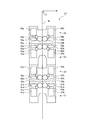
ここで、最も上方側に配置されるスタック24は、図6に示すように、鉛直方向における上方向に沿ったウェブWの搬送経路に対して、左側が表面印刷を行う表面印刷ユニットであり、右側が裏面印刷を行う裏面印刷ユニットである。
Here, as shown in FIG. 6, the
スタック24は、ブランケット胴34a,34bと、版胴44a,44bと、インキ供給装置54a,54bと、湿し装置64a,64bを有している。このインキ供給装置54a,54bは、デジタルインキポンプ方式であって、インキ元ローラ71a,71bと、インキポンプ72a,72bと、インキ受渡しローラ73a,73bと、インキ練りローラ74a,74bと、インキ往復ローラ75a,75bと、インキ着練りローラ76a,76bと、インキ往復ローラ77a,77bと、2つのインキ着ローラ78a,78b,79a,79bから構成されている。また、湿し装置64a,64bは、スプレー方式であって、水ライダローラ81a,81bと、水往復ローラ82a,82bと、水着ローラ83a,83bと、スプレーノズル84a,84bとから構成されている。なお、インキ供給装置54a,54bは、インキつぼ方式であってもよい。
The
インキ受渡しローラ73a,73bは、インキ元ローラ71a,71bのインキを受け渡すものであって、表面が金属または樹脂により形成され、インキ元ローラ71a,71bと所定量のギャップを持って対向するようにフレームに回転自在に支持されている。インキ練りローラ74a,74bは、インキ受渡しローラ73a,73bから受け渡されたインキを練るものであって、表面がゴムにより形成され、インキ受渡しローラ73a,73bに対接するようにフレームに回転自在に支持されている。インキ往復ローラ75a,75bは、インキ練りローラ74a,74bにより練られたインキを幅方向に広げるものであって、表面が金属により形成され、インキ練りローラ74a,74bに対接するようにフレームに回転自在に支持されると共に、軸方向に往復移動可能となっている。
The
インキ着練りローラ76a,76bは、インキ往復ローラ75a,75bから受け渡されたインキを練るものであって、表面がゴムにより形成され、インキ往復ローラ75a,75bに対接するようにフレームに回転自在に支持されている。インキ往復ローラ77a,77bは、インキ着練りローラ76a,76bにより練られたインキを幅方向に広げるものであって、表面が金属により形成され、インキ着練りローラ76a,76bに対接するようにフレームに回転自在に支持されると共に、軸方向に往復移動可能となっている。
The
インキ着ローラ78a,78b,79a,79bは、インキ往復ローラ77a,77bにより幅方向に広げられたインキを受け取って供給するものであって、表面がゴムにより形成され、インキ往復ローラ77a,77bに対接するようにフレームに回転自在に支持されている。そして、インキ受渡しローラ73a,73bとインキ往復ローラ75a,75b,77a,77bは、図示しないギアにより同期駆動するように連結され、図示しない駆動装置により駆動回転可能となっている。また、インキ練りローラ74a,74bとインキ着ローラ78a,78b,79a,79bは、駆動回転する各ローラとの摩擦接触による回転伝達により回転可能となっている。
The
また、水ライダローラ81a,81bは、ローラ間で受け渡される湿し水を練るものであり、表面がゴムにより形成され、隣接するローラに対接するようにフレームに回転自在に支持されている。また、水往復ローラ82a,82bは、隣接するローラ間で受け渡される湿し水を幅方向に広げるものであって、表面が金属により形成され、隣接するローラに対接するようにフレームに回転自在に支持されると共に、軸方向に往復移動可能となっている。水着ローラ83a,83bは、水往復ローラ82a,82bにより幅方向に広げられた湿し水を受け取って供給するものであって、表面がゴムにより形成され、水往復ローラ82a,82bに対接するようにフレームに回転自在に支持されている。スプレーノズル84a,84bは、水往復ローラ82a,82bに対して幅方向に沿って複数配置されている。このとき、複数のスプレーノズル84a,84bのうちのいずれかを作動することで、水往復ローラ82a,82bの軸方向における所定の領域だけに湿し水を供給することができる。そして、水往復ローラ82a,82bは、インキ往復ローラ75a,75b,77a,77bと共にギアにより同期駆動するように連結され、駆動回転可能となっている。また、水ライダローラ81a,81bと水着ローラ83a,83bは、駆動回転する各ローラとの摩擦接触による回転伝達により回転可能となっている。
Further, the
版胴44a,44bは、表面に刷版が巻き付けられる金属ローラであり、水着ローラ83a,83bの湿し水が刷版の非画線部に受け渡された後、インキ着ローラ78a,78b,79a,79bのインキが刷版の画線部に受け渡される。この版胴44a,44bは、インキ着ローラ78a,78b,79a,79bと水着ローラ83a,83bに対接するようにフレームに回転自在に支持されている。ブランケット胴34a,34bは、表面に図示しないブランケット(ゴム)が巻き付けられるゴムローラであり、版胴44a,44bから受け渡されたインキをウェブWに転写するものであって、版胴44a,44bに対接するようにフレームに回転自在に支持されている。そして、版胴44a,44bとブランケット胴34a,34bは、図示しないギアにより同期駆動するように連結され、駆動装置により駆動回転可能となっている。
The
この場合、版胴44a,44bに装着される刷版は、絵柄のある領域(画線部)と絵柄のない領域(非画線部)が形成され、画線部が親油性であり、非画線部が親水性である。そのため、版胴44a,44bに装着された刷版に対して、水着ローラ83a,83bから湿し水が供給された後に、インキ着ローラ78a,78b,79a,79bからインキが供給されると、画線部のみにインキが転写され、非画線部に湿し水が転写される。そして、版胴44a,44bに対してブランケット胴34a,34bが対接して同期回転すると、版胴44a,44bから画線部にあるインキがブランケット胴34a,34bに転写される。
In this case, the printing plates to be mounted on the
なお、スタック24だけ説明したが、他のスタック21,22,23もほぼ同様の構成である。
Although only the
本実施形態のインキローラは、例えば、スタック24で使用されているブランケット胴34a,34b、インキ練りローラ74a,74b、インキ着練りローラ76a,76b、インキ着ローラ78a,78b,79a,79bに適用することができる。
The ink roller of this embodiment is applied to, for example, the
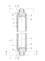
図1は、本実施形態のインキローラを表す断面図、図2は、インキローラの断面を表す図1II−II断面図である。 FIG. 1 is a cross-sectional view showing an ink roller of the present embodiment, and FIG. 2 is a cross-sectional view of FIG. 1II-II showing a cross section of the ink roller.
図1及び図2に示すように、インキローラ10は、金属製のシームド管としての電縫管11と、弾性層としてのゴム層12と、一対の支持軸13,14とを備えている。
As shown in FIGS. 1 and 2, the
電縫管11は、肉厚の一定な金属板を管状に丸めて加工し、周方向の端部同士を溶接して接合することで、軸方向に沿う継ぎ目部11aが形成されたシームド管である。金属板としては、鋼板やアルミ板などが用いられる。ゴム層12は、電縫管11の外周面に全周にわたって密着して設けられており、軸方向の長さが電縫管11より短く設定され、電縫管11は、軸方向の各端部の外周面が露出している。
The
各支持軸13,14は、大径のボス部13a,14aと、小径の軸部13b,14bと有し、このボス部13a,14aと小径の軸部13b,14bが一体に形成されている。ボス部13a,14aは、外径が電縫管11の内径より若干小さく設定される。そして、各支持軸13,14は、大径のボス部13a,14aが電縫管11の軸端部に嵌合し、ボス部13a,14aの外周部における軸端と電縫管11の内周部における軸端とが溶接W1,W2により固定されている。このとき、電縫管11と各支持軸13,14のボス部13a,14aとは、継ぎ目部11aを除いた接触部が溶接により接合される。また、支持軸13,14は、中心Oから径方向にずれた位置に軸方向に沿う貫通孔13c,14cが形成されており、電縫管11との溶接時における熱膨張による変形が防止される。そして、支持軸13,14は、軸部13b,14bが軸受15,16を介して印刷機のフレーム17,18に回転自在に支持されている。
Each of the
図3は、インキローラの寸法を表す概略である。 FIG. 3 is a schematic diagram showing the dimensions of the ink roller.
また、インローラ10は、図3に示すように、電縫管11の厚さT1が電縫管11の内径D、つまり、空洞部の直径の4%以上で、且つ、8%以下に設定されている。また、インキローラ10は、電縫管11の厚さT1がゴム層12の厚さT2の40%以上で、且つ、80%以下に設定されている。この場合、インキローラ10の外径は、例えば、120mm前後であって、電縫管11の厚さT1は、3.5mmから7mmの範囲、ゴム層T2の厚さは、7mmから12mmの範囲、電縫管11の内径(空洞部の直径)Dは、82mmから99mmの範囲が理想的である。
In the in-
電縫管11の厚さT1を電縫管11の内径Dの直径の4%以上で、且つ、8%以下に設定し、電縫管11の厚さT1をゴム層12の厚さT2の40%以上で、且つ、80%以下に設定することで、電縫管11の剛性を確保する一方で、総重量と慣性を低減することができる。また、インキローラ10の高速回転時の摩擦による熱膨張の影響を受けにくくなり、熱膨張量が減少して駆動力を低減することができる。また、インキローラ10と他のローラとのニップによる変形が少なくなるため、インキ練り動作によりインキを平滑化しやすくなる。
The thickness T1 of the
この場合、インキローラ10の外径を従来から変更せずに、電縫管11の厚さT1やゴム層12の厚さT2を適正値としている。従来のインキローラは、金属層(鉄)の外径を小さく、且つ、偏肉加工が可能な厚さまで薄くすることで軽量化していたが、この設定では、剛性は確保されるものの、鋼管厚の限界があり、重量物となっていた。また、インキローラの外径と金属層(鉄)の外径との差は、ゴム層を厚くすることで調整していたので、巻き替えに使用するゴム量が多く必要だった。
In this case, the thickness T1 of the
また、インキローラには、金属層(素管)にカーボン素材を使用したものもあるが、カーボン素材場合、鉄鋼材料並みの剛性を得るには非常に高価で、大径となる場合が多い。また、ゴム巻き替えの際、ゴムを削るときにカーボン表面が毛羽立ってしまい、ゴムがうまく外れなかったり、カーボン自体を削ってしまって、径が変わったり、場合によっては再使用不可の不具合が発生することもあった。また、カーボンと鉄の接着部分が、ゴム巻き替え時の熱で傷む場合があり、ゴム巻き替え再加工回数の制限があった。そのため、カーボン素材を使用したものは、繰り返し加工するには限界があり、ローラ寿命も短い傾向がある。 Some ink rollers use a carbon material for the metal layer (element tube). However, in the case of a carbon material, it is very expensive and often has a large diameter in order to obtain the same rigidity as a steel material. Also, when rewinding rubber, the carbon surface becomes fuzzy when scraping the rubber, the rubber does not come off well, the carbon itself is shaved, the diameter changes, and in some cases a non-reusable malfunction occurs. There was also. In addition, the bonded portion of carbon and iron may be damaged by heat at the time of rubber rewinding, and there has been a limit on the number of times of rubber rewinding rework. For this reason, those using a carbon material have a limit for repeated processing and tend to have a short roller life.
更に、インキローラ10は、ゴム巻き部と軸部を含めた軸方向のローラ総長さが2000mm以下の範囲に設定されている。この場合の軸方向長さとは、支持軸13,14を含めた長さである。なお、本実施形態の新聞用オフセット輪転印刷機にて、インキローラ10のローラ総長さの下限は1200mmであるが、刷版の幅方向長さ、及び刷版の幅方向の装着数により可変である。また、インキローラ10は、重量が50kg以下に設定されている。この場合、好ましくは、重量が45kg以下であって、重量が40kg以下であると最適である。このインキローラ10の重量に関する規定は、欧州にて、EN1005−2「Safety of machinery − Human physical performance Part2:Manual handling of machinery and component parts of machinery」によるものである。また、日本では、「女性労働基準規則及び年少者労働基準規則」によるものである。
Further, the total length of the roller in the axial direction including the rubber winding portion and the shaft portion is set to a range of 2000 mm or less. The axial length in this case is the length including the
このように本実施形態のインキローラにあっては、周方向の一部に継ぎ目部11aを有する金属製の電縫管11と、電縫管11の外周面に形成されたゴム層12と、電縫管11における軸方向の両端部に固定される一対の支持軸13,14とを設けている。
As described above, in the ink roller of the present embodiment, the metal
従って、継ぎ目部11aを有する電縫管11の外周面にゴム層12を形成してインキローラ10を構成することで、鋼管を使用する場合に比べて、鋼管の外周面及び内周面の加工を不要として製造コストを低減することができ、また、肉厚を薄くすることで軽量化を図ることができる。
Therefore, by forming the
本実施形態のインキローラでは、肉厚の一定な金属板を管状に丸めて加工し、周方向の端部同士を溶接して継ぎ目部11aを形成する電縫管11としている。従って、電縫管11を使用することで、低コスト化、軽量化、高精度化を図ることができる。
In the ink roller according to the present embodiment, a metal plate having a constant thickness is rounded and processed into a tubular shape, and the end portions in the circumferential direction are welded to form the
本実施形態のインキローラでは、電縫管11の端部と支持軸13,14とを、継ぎ目部11aを除いた接触部で溶接により接合している。従って、電縫管11の端部と支持軸13,14とを溶接するとき、電縫管11の継ぎ目部11aを除いて溶接することで、溶接熱による継ぎ目部11aの変形を防止することができる。
In the ink roller of the present embodiment, the end portion of the
本実施形態のインキローラでは、電縫管11の厚さT1を電縫管11の内径Dの4%より大きく8%より小さく設定すると共に、電縫管11の厚さT1をゴム層12の厚さT2の50%より大きく75%より小さく設定している。従って、電縫管11の剛性を確保する一方で、総重量を低減することができ、また、電縫管11の厚さT1がゴム層12の厚さT2より薄くなるため、インキローラ10の高速回転時の摩擦による熱膨張の影響を受けにくくなり、熱膨張量が減少して駆動力を低減することができる。
In the ink roller of the present embodiment, the thickness T1 of the
本実施形態のインキローラでは、ゴム巻き部と軸部を含めた軸方向のローラ総長さが2000mm以下の範囲とし、且つ、重量を50kg以下に設定している。インキを練るために十分な剛性を確保することができると共に、軽量化を図ることができ、インキローラ10の組付性やメンテナンス性を向上することができる。
In the ink roller according to the present embodiment, the total length of the roller including the rubber winding portion and the shaft portion is set to a range of 2000 mm or less, and the weight is set to 50 kg or less. In addition to ensuring sufficient rigidity to knead the ink, it is possible to reduce the weight and improve the assembling property and maintenance property of the
また、本実施形態の印刷機にあっては、インキローラ10を有してインキを供給するインキ供給装置51a,51b,52a,52b,53a,53b,54a,54bと、インキ供給装置51a,51b,52a,52b,53a,53b,54a,54bから外周部に装着された刷版にインキが供給される版胴41a,41b,42a,42b,43a,43b,44a,44bと、版胴41a,41b,42a,42b,43a,43b,44a,44bから受け取ったインキの画像をウェブWに転写するブランケット胴31a,31b,32a,32b,33a,33b,34a,34bとを設けている。
Further, in the printing machine of the present embodiment, the
従って、電縫管11の外周面にゴム層12を形成してインキローラ10を構成し、このインキローラ10をインキ供給装置51a,51b,52a,52b,53a,53b,54a,54bのローラに適用することで、インキ供給装置51a,51b,52a,52b,53a,53b,54a,54bの製造コストを低減することができると共に、肉厚を薄くして軽量化を図ることができる。その結果、印刷機の製造コストを低減することができると共に、メンテナンス性を図ることができる。
Accordingly, the
なお、上述した実施形態では、印刷機として新聞用オフセット輪転印刷機Pを適用したが、商業用オフセット輪転印刷機やオフセット枚葉印刷機などに適用してもよい。また、インキローラ10を、ブランケット胴31a,31b,32a,32b,33a,33b,34a,34b、インキ練りローラ74a,74b、インキ着練りローラ76a,76b、インキ着ローラ78a,78b,79a,79bに適用して説明したが、弾性層を有する別のインキローラに敵宇してもよい。
In the above-described embodiment, the newspaper offset rotary printing press P is applied as the printing press. However, it may be applied to a commercial offset rotary printing press or an offset sheet-fed printing press. Further, the
P 新聞用オフセット輪転印刷機(印刷機)
R 給紙装置
R1〜R7 給紙ユニット
I インフィード装置
I1〜I7 インフィードユニット
U 印刷装置
U1〜U6,U11〜U62 印刷ユニット
D ウェブパス装置
D1,D2 ウェブパスユニット
F 折機
F1,F2 折ユニット
10 インキローラ
11 電縫管(シームド管)
11a 継ぎ目部
12 ゴム層(弾性層)
13,14 支持軸
21,22,23,24 スタック
31a,31b,32a,32b,33a,33b,34a,34b ブランケット胴
41a,41b,42a,42b,43a,43b,44a,44b 版胴
51a,51b,52a,52b,53a,53b,54a,54b インキ供給装置
61a,61b,62a,62b,63a,63b,64a,64b 湿し装置
74a,74b インキ練りローラ
76a,76b インキ着練りローラ
78a,78b,79a,79b インキ着ローラ
W ウェブ
P Newspaper web offset press (printer)
R paper feeding device R1 to R7 paper feeding unit I infeed device I1 to I7 infeed unit U printing device U1 to U6, U11 to U62 printing unit D web pass device D1, D2 web pass unit F folding machine F1,
13, 14
Claims (6)
前記シームド管の外周面に形成された弾性層と、
前記シームド管における軸方向の両端部に固定される一対の支持軸と、
を備えることを特徴とするインキローラ。 A metal seamed pipe having a seam part in a circumferential part;
An elastic layer formed on the outer peripheral surface of the seamed tube;
A pair of support shafts fixed to both axial ends of the seamed tube;
An ink roller comprising:
前記インキ供給装置から外周部に装着された刷版にインキが供給される版胴と、
前記版胴から受け取ったインキの画像をウェブに転写するブランケット胴と、
を備えることを特徴とする印刷機。 An ink supply device that has the ink roller according to any one of claims 1 to 5 and supplies ink,
A plate cylinder from which ink is supplied to the printing plate mounted on the outer periphery from the ink supply device;
A blanket cylinder for transferring an image of ink received from the plate cylinder to a web;
A printing machine comprising:
Priority Applications (1)
| Application Number | Priority Date | Filing Date | Title |
|---|---|---|---|
| JP2016035970A JP6461027B2 (en) | 2016-02-26 | 2016-02-26 | Ink roller and printing machine |
Applications Claiming Priority (1)
| Application Number | Priority Date | Filing Date | Title |
|---|---|---|---|
| JP2016035970A JP6461027B2 (en) | 2016-02-26 | 2016-02-26 | Ink roller and printing machine |
Publications (2)
| Publication Number | Publication Date |
|---|---|
| JP2017149115A true JP2017149115A (en) | 2017-08-31 |
| JP6461027B2 JP6461027B2 (en) | 2019-01-30 |
Family
ID=59741941
Family Applications (1)
| Application Number | Title | Priority Date | Filing Date |
|---|---|---|---|
| JP2016035970A Active JP6461027B2 (en) | 2016-02-26 | 2016-02-26 | Ink roller and printing machine |
Country Status (1)
| Country | Link |
|---|---|
| JP (1) | JP6461027B2 (en) |
Cited By (2)
| Publication number | Priority date | Publication date | Assignee | Title |
|---|---|---|---|---|
| CN109591435A (en) * | 2019-01-23 | 2019-04-09 | 北京柏力行彩印有限公司 | Flexographic printing apparatus and its rubber sleeve Replacement procedure |
| CN111255780A (en) * | 2020-03-16 | 2020-06-09 | 中山市谷川金属制品有限公司 | High-tensile-strength-resistant Y-shaped pipe |
Citations (5)
| Publication number | Priority date | Publication date | Assignee | Title |
|---|---|---|---|---|
| JPH0648063A (en) * | 1992-05-29 | 1994-02-22 | Man Roland Druckmas Ag | Rubber blanket for offset printing and its production |
| JPH0890758A (en) * | 1994-09-15 | 1996-04-09 | Man Roland Druckmas Ag | Carrier sleeve for printing plate and transfer plate |
| JPH08290551A (en) * | 1995-04-20 | 1996-11-05 | Mitsubishi Heavy Ind Ltd | Rubber roller |
| US20030075062A1 (en) * | 2001-10-20 | 2003-04-24 | Man Roland Druckmaschinen Ag | Sleeve-like printing or transfer form and device for chamfering the longitudinal ends of a sleeve-like printing or transfer form |
| JP2008094030A (en) * | 2006-10-13 | 2008-04-24 | Asahi Kasei Chemicals Corp | Hollow cylindrical support for printing base material |
-
2016
- 2016-02-26 JP JP2016035970A patent/JP6461027B2/en active Active
Patent Citations (5)
| Publication number | Priority date | Publication date | Assignee | Title |
|---|---|---|---|---|
| JPH0648063A (en) * | 1992-05-29 | 1994-02-22 | Man Roland Druckmas Ag | Rubber blanket for offset printing and its production |
| JPH0890758A (en) * | 1994-09-15 | 1996-04-09 | Man Roland Druckmas Ag | Carrier sleeve for printing plate and transfer plate |
| JPH08290551A (en) * | 1995-04-20 | 1996-11-05 | Mitsubishi Heavy Ind Ltd | Rubber roller |
| US20030075062A1 (en) * | 2001-10-20 | 2003-04-24 | Man Roland Druckmaschinen Ag | Sleeve-like printing or transfer form and device for chamfering the longitudinal ends of a sleeve-like printing or transfer form |
| JP2008094030A (en) * | 2006-10-13 | 2008-04-24 | Asahi Kasei Chemicals Corp | Hollow cylindrical support for printing base material |
Cited By (2)
| Publication number | Priority date | Publication date | Assignee | Title |
|---|---|---|---|---|
| CN109591435A (en) * | 2019-01-23 | 2019-04-09 | 北京柏力行彩印有限公司 | Flexographic printing apparatus and its rubber sleeve Replacement procedure |
| CN111255780A (en) * | 2020-03-16 | 2020-06-09 | 中山市谷川金属制品有限公司 | High-tensile-strength-resistant Y-shaped pipe |
Also Published As
| Publication number | Publication date |
|---|---|
| JP6461027B2 (en) | 2019-01-30 |
Similar Documents
| Publication | Publication Date | Title |
|---|---|---|
| US8544385B2 (en) | Printing press with different fixed cutoffs and method | |
| JP6449051B2 (en) | Control device and method for printing press and printing press | |
| JP6461027B2 (en) | Ink roller and printing machine | |
| JP5465886B2 (en) | Blanket for printing and manufacturing method thereof, blanket cylinder and printing machine | |
| JP6278356B2 (en) | Paper winding prevention device and printing machine | |
| JP5335071B2 (en) | Infinite variable cut-off printing machine | |
| WO2015097754A1 (en) | Printer and ink supply method | |
| JP7100986B2 (en) | Blanket and blanket body and printing press | |
| JP6456187B2 (en) | Printing unit and printing machine | |
| JP2008201092A (en) | Printer | |
| JP5972596B2 (en) | Web conveying device and printing machine | |
| JP5859703B2 (en) | Printer | |
| EP2146850B1 (en) | Printing press with different fixed cutoffs and method | |
| WO2011104832A1 (en) | Printing blanket, manufacturing method therefor, blanket drum, and printer | |
| JP2017189964A (en) | Printing cylinder, printing machine, and blanket | |
| JP2010201650A (en) | Printing machine and method for operating printing machine | |
| JP2013006282A (en) | Printing machine | |
| JPH081904A (en) | Gapless blanket cylinder, and gapless offset press employing gapless blanket cylinder | |
| JP2022057411A (en) | Nip monitoring device of printing pat, and off-set web press | |
| JP2009233982A (en) | Roller deformation detecting apparatus and its method | |
| JP4414170B2 (en) | Multicolor sheet-fed printing machine | |
| JP2009073053A (en) | Nip adjusting mechanism and printer | |
| JP2009220361A (en) | Dampening device for printer, and printer | |
| JP2021062560A (en) | Fanout suppression control device and printer and print control method | |
| EP2280825A1 (en) | Variable cut off printing press having flexible plate and blanket |
Legal Events
| Date | Code | Title | Description |
|---|---|---|---|
| A711 | Notification of change in applicant |
Free format text: JAPANESE INTERMEDIATE CODE: A712 Effective date: 20171219 |
|
| A625 | Written request for application examination (by other person) |
Free format text: JAPANESE INTERMEDIATE CODE: A625 Effective date: 20180220 |
|
| TRDD | Decision of grant or rejection written | ||
| A977 | Report on retrieval |
Free format text: JAPANESE INTERMEDIATE CODE: A971007 Effective date: 20181114 |
|
| A01 | Written decision to grant a patent or to grant a registration (utility model) |
Free format text: JAPANESE INTERMEDIATE CODE: A01 Effective date: 20181127 |
|
| A61 | First payment of annual fees (during grant procedure) |
Free format text: JAPANESE INTERMEDIATE CODE: A61 Effective date: 20181225 |
|
| R150 | Certificate of patent or registration of utility model |
Ref document number: 6461027 Country of ref document: JP Free format text: JAPANESE INTERMEDIATE CODE: R150 |