JP2017148657A - Image capture unit in surgical instrument - Google Patents
Image capture unit in surgical instrument Download PDFInfo
- Publication number
- JP2017148657A JP2017148657A JP2017114998A JP2017114998A JP2017148657A JP 2017148657 A JP2017148657 A JP 2017148657A JP 2017114998 A JP2017114998 A JP 2017114998A JP 2017114998 A JP2017114998 A JP 2017114998A JP 2017148657 A JP2017148657 A JP 2017148657A
- Authority
- JP
- Japan
- Prior art keywords
- image capture
- image
- sensor
- light
- capture sensor
- Prior art date
- Legal status (The legal status is an assumption and is not a legal conclusion. Google has not performed a legal analysis and makes no representation as to the accuracy of the status listed.)
- Granted
Links
- 230000003287 optical effect Effects 0.000 claims abstract description 250
- 238000005286 illumination Methods 0.000 claims description 117
- 238000000034 method Methods 0.000 claims description 87
- 230000010287 polarization Effects 0.000 claims description 62
- 239000013598 vector Substances 0.000 abstract description 73
- 230000001965 increasing effect Effects 0.000 abstract description 12
- 238000000576 coating method Methods 0.000 description 68
- 239000011248 coating agent Substances 0.000 description 65
- 230000008569 process Effects 0.000 description 57
- 230000009977 dual effect Effects 0.000 description 50
- 230000000712 assembly Effects 0.000 description 40
- 238000000429 assembly Methods 0.000 description 40
- 238000003384 imaging method Methods 0.000 description 32
- 230000005284 excitation Effects 0.000 description 21
- 238000012937 correction Methods 0.000 description 18
- 238000010586 diagram Methods 0.000 description 17
- 230000006870 function Effects 0.000 description 17
- 238000012545 processing Methods 0.000 description 17
- 238000005070 sampling Methods 0.000 description 17
- 230000008901 benefit Effects 0.000 description 12
- 239000000463 material Substances 0.000 description 11
- 238000013507 mapping Methods 0.000 description 10
- 239000003086 colorant Substances 0.000 description 8
- 238000002189 fluorescence spectrum Methods 0.000 description 8
- 238000001228 spectrum Methods 0.000 description 8
- 230000005540 biological transmission Effects 0.000 description 7
- 239000011159 matrix material Substances 0.000 description 7
- 239000000758 substrate Substances 0.000 description 7
- 101100248200 Arabidopsis thaliana RGGB gene Proteins 0.000 description 6
- 238000013461 design Methods 0.000 description 6
- 239000010410 layer Substances 0.000 description 6
- 239000004973 liquid crystal related substance Substances 0.000 description 6
- 239000004065 semiconductor Substances 0.000 description 6
- 238000000926 separation method Methods 0.000 description 6
- 230000026676 system process Effects 0.000 description 6
- 230000000295 complement effect Effects 0.000 description 5
- 238000013459 approach Methods 0.000 description 4
- 239000000919 ceramic Substances 0.000 description 4
- 230000008859 change Effects 0.000 description 4
- 238000004590 computer program Methods 0.000 description 4
- 229910052724 xenon Inorganic materials 0.000 description 4
- FHNFHKCVQCLJFQ-UHFFFAOYSA-N xenon atom Chemical compound [Xe] FHNFHKCVQCLJFQ-UHFFFAOYSA-N 0.000 description 4
- 230000004075 alteration Effects 0.000 description 3
- 210000002858 crystal cell Anatomy 0.000 description 3
- 239000000975 dye Substances 0.000 description 3
- GNBHRKFJIUUOQI-UHFFFAOYSA-N fluorescein Chemical compound O1C(=O)C2=CC=CC=C2C21C1=CC=C(O)C=C1OC1=CC(O)=CC=C21 GNBHRKFJIUUOQI-UHFFFAOYSA-N 0.000 description 3
- 239000011521 glass Substances 0.000 description 3
- 230000003595 spectral effect Effects 0.000 description 3
- 238000001429 visible spectrum Methods 0.000 description 3
- 230000000007 visual effect Effects 0.000 description 3
- 239000003795 chemical substances by application Substances 0.000 description 2
- 238000004040 coloring Methods 0.000 description 2
- 239000002131 composite material Substances 0.000 description 2
- 238000007796 conventional method Methods 0.000 description 2
- 230000002708 enhancing effect Effects 0.000 description 2
- 238000000799 fluorescence microscopy Methods 0.000 description 2
- 102000034287 fluorescent proteins Human genes 0.000 description 2
- 108091006047 fluorescent proteins Proteins 0.000 description 2
- 238000001727 in vivo Methods 0.000 description 2
- 238000004519 manufacturing process Methods 0.000 description 2
- 229910052751 metal Inorganic materials 0.000 description 2
- 239000002184 metal Substances 0.000 description 2
- 210000005036 nerve Anatomy 0.000 description 2
- 239000013307 optical fiber Substances 0.000 description 2
- 238000007639 printing Methods 0.000 description 2
- 230000004044 response Effects 0.000 description 2
- 229920006395 saturated elastomer Polymers 0.000 description 2
- 239000000243 solution Substances 0.000 description 2
- 239000002344 surface layer Substances 0.000 description 2
- 238000001356 surgical procedure Methods 0.000 description 2
- 238000012935 Averaging Methods 0.000 description 1
- 201000009273 Endometriosis Diseases 0.000 description 1
- 206010027646 Miosis Diseases 0.000 description 1
- 206010028980 Neoplasm Diseases 0.000 description 1
- OAICVXFJPJFONN-UHFFFAOYSA-N Phosphorus Chemical compound [P] OAICVXFJPJFONN-UHFFFAOYSA-N 0.000 description 1
- XUIMIQQOPSSXEZ-UHFFFAOYSA-N Silicon Chemical compound [Si] XUIMIQQOPSSXEZ-UHFFFAOYSA-N 0.000 description 1
- 238000003491 array Methods 0.000 description 1
- 238000010420 art technique Methods 0.000 description 1
- 238000005452 bending Methods 0.000 description 1
- 230000000903 blocking effect Effects 0.000 description 1
- 238000010276 construction Methods 0.000 description 1
- 230000001419 dependent effect Effects 0.000 description 1
- 201000010099 disease Diseases 0.000 description 1
- 208000037265 diseases, disorders, signs and symptoms Diseases 0.000 description 1
- 238000000295 emission spectrum Methods 0.000 description 1
- 238000005516 engineering process Methods 0.000 description 1
- 239000007850 fluorescent dye Substances 0.000 description 1
- 210000003128 head Anatomy 0.000 description 1
- 238000002329 infrared spectrum Methods 0.000 description 1
- 238000002347 injection Methods 0.000 description 1
- 239000007924 injection Substances 0.000 description 1
- 208000014674 injury Diseases 0.000 description 1
- 239000003550 marker Substances 0.000 description 1
- 230000007246 mechanism Effects 0.000 description 1
- QSHDDOUJBYECFT-UHFFFAOYSA-N mercury Chemical compound [Hg] QSHDDOUJBYECFT-UHFFFAOYSA-N 0.000 description 1
- 229910052753 mercury Inorganic materials 0.000 description 1
- 238000012978 minimally invasive surgical procedure Methods 0.000 description 1
- 238000005457 optimization Methods 0.000 description 1
- 230000001575 pathological effect Effects 0.000 description 1
- 230000002093 peripheral effect Effects 0.000 description 1
- 238000011084 recovery Methods 0.000 description 1
- 238000009877 rendering Methods 0.000 description 1
- 238000009738 saturating Methods 0.000 description 1
- 229910052710 silicon Inorganic materials 0.000 description 1
- 239000010703 silicon Substances 0.000 description 1
- 239000007787 solid Substances 0.000 description 1
- 230000003068 static effect Effects 0.000 description 1
- 238000003860 storage Methods 0.000 description 1
- 238000006467 substitution reaction Methods 0.000 description 1
- 230000002123 temporal effect Effects 0.000 description 1
- 210000002435 tendon Anatomy 0.000 description 1
- 238000012546 transfer Methods 0.000 description 1
- 230000008733 trauma Effects 0.000 description 1
- 230000001960 triggered effect Effects 0.000 description 1
- WFKWXMTUELFFGS-UHFFFAOYSA-N tungsten Chemical compound [W] WFKWXMTUELFFGS-UHFFFAOYSA-N 0.000 description 1
- 229910052721 tungsten Inorganic materials 0.000 description 1
- 239000010937 tungsten Substances 0.000 description 1
- 238000012800 visualization Methods 0.000 description 1
Images


Classifications
-
- A—HUMAN NECESSITIES
- A61—MEDICAL OR VETERINARY SCIENCE; HYGIENE
- A61B—DIAGNOSIS; SURGERY; IDENTIFICATION
- A61B1/00—Instruments for performing medical examinations of the interior of cavities or tubes of the body by visual or photographical inspection, e.g. endoscopes; Illuminating arrangements therefor
- A61B1/00002—Operational features of endoscopes
- A61B1/00004—Operational features of endoscopes characterised by electronic signal processing
- A61B1/00009—Operational features of endoscopes characterised by electronic signal processing of image signals during a use of endoscope
- A61B1/000094—Operational features of endoscopes characterised by electronic signal processing of image signals during a use of endoscope extracting biological structures
-
- A—HUMAN NECESSITIES
- A61—MEDICAL OR VETERINARY SCIENCE; HYGIENE
- A61B—DIAGNOSIS; SURGERY; IDENTIFICATION
- A61B1/00—Instruments for performing medical examinations of the interior of cavities or tubes of the body by visual or photographical inspection, e.g. endoscopes; Illuminating arrangements therefor
- A61B1/00002—Operational features of endoscopes
- A61B1/00004—Operational features of endoscopes characterised by electronic signal processing
- A61B1/00009—Operational features of endoscopes characterised by electronic signal processing of image signals during a use of endoscope
- A61B1/000095—Operational features of endoscopes characterised by electronic signal processing of image signals during a use of endoscope for image enhancement
-
- A—HUMAN NECESSITIES
- A61—MEDICAL OR VETERINARY SCIENCE; HYGIENE
- A61B—DIAGNOSIS; SURGERY; IDENTIFICATION
- A61B1/00—Instruments for performing medical examinations of the interior of cavities or tubes of the body by visual or photographical inspection, e.g. endoscopes; Illuminating arrangements therefor
- A61B1/00064—Constructional details of the endoscope body
- A61B1/00071—Insertion part of the endoscope body
- A61B1/0008—Insertion part of the endoscope body characterised by distal tip features
- A61B1/00096—Optical elements
-
- A—HUMAN NECESSITIES
- A61—MEDICAL OR VETERINARY SCIENCE; HYGIENE
- A61B—DIAGNOSIS; SURGERY; IDENTIFICATION
- A61B1/00—Instruments for performing medical examinations of the interior of cavities or tubes of the body by visual or photographical inspection, e.g. endoscopes; Illuminating arrangements therefor
- A61B1/00163—Optical arrangements
- A61B1/00193—Optical arrangements adapted for stereoscopic vision
-
- A—HUMAN NECESSITIES
- A61—MEDICAL OR VETERINARY SCIENCE; HYGIENE
- A61B—DIAGNOSIS; SURGERY; IDENTIFICATION
- A61B1/00—Instruments for performing medical examinations of the interior of cavities or tubes of the body by visual or photographical inspection, e.g. endoscopes; Illuminating arrangements therefor
- A61B1/04—Instruments for performing medical examinations of the interior of cavities or tubes of the body by visual or photographical inspection, e.g. endoscopes; Illuminating arrangements therefor combined with photographic or television appliances
- A61B1/045—Control thereof
-
- A—HUMAN NECESSITIES
- A61—MEDICAL OR VETERINARY SCIENCE; HYGIENE
- A61B—DIAGNOSIS; SURGERY; IDENTIFICATION
- A61B1/00—Instruments for performing medical examinations of the interior of cavities or tubes of the body by visual or photographical inspection, e.g. endoscopes; Illuminating arrangements therefor
- A61B1/04—Instruments for performing medical examinations of the interior of cavities or tubes of the body by visual or photographical inspection, e.g. endoscopes; Illuminating arrangements therefor combined with photographic or television appliances
- A61B1/05—Instruments for performing medical examinations of the interior of cavities or tubes of the body by visual or photographical inspection, e.g. endoscopes; Illuminating arrangements therefor combined with photographic or television appliances characterised by the image sensor, e.g. camera, being in the distal end portion
- A61B1/051—Details of CCD assembly
-
- A—HUMAN NECESSITIES
- A61—MEDICAL OR VETERINARY SCIENCE; HYGIENE
- A61B—DIAGNOSIS; SURGERY; IDENTIFICATION
- A61B90/00—Instruments, implements or accessories specially adapted for surgery or diagnosis and not covered by any of the groups A61B1/00 - A61B50/00, e.g. for luxation treatment or for protecting wound edges
- A61B90/36—Image-producing devices or illumination devices not otherwise provided for
- A61B90/37—Surgical systems with images on a monitor during operation
-
- A—HUMAN NECESSITIES
- A61—MEDICAL OR VETERINARY SCIENCE; HYGIENE
- A61B—DIAGNOSIS; SURGERY; IDENTIFICATION
- A61B18/00—Surgical instruments, devices or methods for transferring non-mechanical forms of energy to or from the body
- A61B2018/00982—Surgical instruments, devices or methods for transferring non-mechanical forms of energy to or from the body combined with or comprising means for visual or photographic inspections inside the body, e.g. endoscopes
-
- A—HUMAN NECESSITIES
- A61—MEDICAL OR VETERINARY SCIENCE; HYGIENE
- A61B—DIAGNOSIS; SURGERY; IDENTIFICATION
- A61B90/00—Instruments, implements or accessories specially adapted for surgery or diagnosis and not covered by any of the groups A61B1/00 - A61B50/00, e.g. for luxation treatment or for protecting wound edges
- A61B90/36—Image-producing devices or illumination devices not otherwise provided for
- A61B90/361—Image-producing devices, e.g. surgical cameras
- A61B2090/3618—Image-producing devices, e.g. surgical cameras with a mirror
-
- A—HUMAN NECESSITIES
- A61—MEDICAL OR VETERINARY SCIENCE; HYGIENE
- A61B—DIAGNOSIS; SURGERY; IDENTIFICATION
- A61B90/00—Instruments, implements or accessories specially adapted for surgery or diagnosis and not covered by any of the groups A61B1/00 - A61B50/00, e.g. for luxation treatment or for protecting wound edges
- A61B90/36—Image-producing devices or illumination devices not otherwise provided for
- A61B90/37—Surgical systems with images on a monitor during operation
- A61B2090/371—Surgical systems with images on a monitor during operation with simultaneous use of two cameras
-
- A—HUMAN NECESSITIES
- A61—MEDICAL OR VETERINARY SCIENCE; HYGIENE
- A61B—DIAGNOSIS; SURGERY; IDENTIFICATION
- A61B90/00—Instruments, implements or accessories specially adapted for surgery or diagnosis and not covered by any of the groups A61B1/00 - A61B50/00, e.g. for luxation treatment or for protecting wound edges
- A61B90/36—Image-producing devices or illumination devices not otherwise provided for
- A61B90/361—Image-producing devices, e.g. surgical cameras
Landscapes
- Health & Medical Sciences (AREA)
- Life Sciences & Earth Sciences (AREA)
- Surgery (AREA)
- Engineering & Computer Science (AREA)
- Nuclear Medicine, Radiotherapy & Molecular Imaging (AREA)
- General Health & Medical Sciences (AREA)
- Veterinary Medicine (AREA)
- Public Health (AREA)
- Pathology (AREA)
- Animal Behavior & Ethology (AREA)
- Molecular Biology (AREA)
- Biomedical Technology (AREA)
- Heart & Thoracic Surgery (AREA)
- Medical Informatics (AREA)
- Radiology & Medical Imaging (AREA)
- Physics & Mathematics (AREA)
- Optics & Photonics (AREA)
- Biophysics (AREA)
- Signal Processing (AREA)
- Oral & Maxillofacial Surgery (AREA)
- Gynecology & Obstetrics (AREA)
- Endoscopes (AREA)
- Multimedia (AREA)
- Astronomy & Astrophysics (AREA)
- General Physics & Mathematics (AREA)
- Instruments For Viewing The Inside Of Hollow Bodies (AREA)
- Studio Devices (AREA)
- Closed-Circuit Television Systems (AREA)
- Testing, Inspecting, Measuring Of Stereoscopic Televisions And Televisions (AREA)
- Stroboscope Apparatuses (AREA)
- Stereoscopic And Panoramic Photography (AREA)
- Structure And Mechanism Of Cameras (AREA)
Abstract
Description
本発明の態様は、概して内視鏡撮像に関し、さらに詳細には、共通の前端部光学的構造から複数の画像取込みセンサに光を取り込むことに関する。 Aspects of the invention relate generally to endoscopic imaging, and more particularly to capturing light from a common front end optical structure into a plurality of image capture sensors.
米国カリフォルニア州SunnyvaleのIntuitive Surgical社製のda Vinci(登録商標)外科手術システムは、体への外傷が小さい、回復が早い、入院期間が短いなど多くの利点を患者にもたらす、低侵襲遠隔走査型外科手術システムである。da Vinci(登録商標)外科手術システム(例えばモデルIS3000、da Vinci(登録商標)Si HD)の1つの重要な要素は、可視画像の2チャネル(すなわち左右)ビデオ取込みおよび表示を行って、執刀医に立体視を提供する機能である。このような電子立体撮像システムは、高精細度のビデオ画像を執刀医に出力することができ、ズームなどの機能によって、執刀医が特定の組織の種類および特徴を識別し、より高い精度で作業することを可能にする「拡大」ビューを提供することができる。 Da Vinci (R) surgical system from Intuitive Surgical, Sunnyvale, California, USA, is a minimally invasive telescan that offers many benefits to patients, including small trauma, fast recovery, and short hospital stay Surgical system. One important element of the da Vinci® surgical system (eg, model IS3000, da Vinci® Si HD) is the two-channel (ie, left and right) video capture and display of visible images, and the surgeon This is a function that provides a stereoscopic view. Such electronic stereo imaging systems can output high-definition video images to the surgeon, and features such as zoom allow the surgeon to identify specific tissue types and features and work with higher accuracy An “enlarged” view can be provided that allows
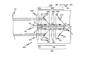
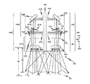
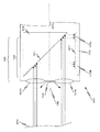
通常、低侵襲外科手術システムでは、画像取込みシステムが、立体内視鏡の近位端部(外科手術部位から離れた端部)に結合される。しかし、一部の立体内視鏡は、画像取込み構成要素を内視鏡の遠位端部(外科手術部位に最も近い端部)に備えている。図1Aから図1Dは、米国特許第4873572号(1988年2月24日出願)に記載の立体内視鏡の遠位端部にある画像取込みセンサの構成の例を示す図である。 Typically, in a minimally invasive surgical system, an image capture system is coupled to the proximal end of the stereoscope (the end away from the surgical site). However, some stereoscopic endoscopes include an image capture component at the distal end of the endoscope (the end closest to the surgical site). 1A to 1D are diagrams showing an example of a configuration of an image capturing sensor at a distal end portion of a stereoscopic endoscope described in US Pat. No. 4,873,572 (filed on Feb. 24, 1988).
図1Aでは、内視鏡の遠位端部100Aは、内視鏡の長手方向軸線133Aと一致する中心線を有する板状パッケージ113Aを含む。2つの電荷結合素子(CCD)114A1および114A2が、パッケージ113Aの対向する表面上に取り付けられる。2つの対物レンズ115A1および115A2が、内視鏡の長手方向軸線133Aの両側に対称に配置される。ミラー116A1および116A2が、それぞれ対物レンズ115A1および115A2の光学軸線上に対照的に配置される。内視鏡外部の物体によって反射された光は、対物レンズ115A1および115A2を通過して、ミラー116A1および116A2によってCCD114A1および114A2の撮像面上に反射される。CCD114A1および114A2からのビデオ信号は、内視鏡外部のビデオ・プロセッサに伝送される。
In FIG. 1A, the
図1Bでは、内視鏡の遠位端部100Bは、図1Aの対物レンズ115A1および115A2と同じように配置された2つの対物レンズ115B1および115B2を含む。ミラー116B1および116B2が、ミラー表面を内視鏡の長手方向軸線133Bと平行に、ただし長手方向軸線133bからずらして取り付けられる。内視鏡外部の物体によって反射された光は、対物レンズ115B1および115B2を通過して、ミラー116B1および116B2によって屈折プリズム117B1および117B2に反射される。プリズム117B1および117B2からの光路は、CCD114B1および114B2の撮像面に向かう。CCD114B1および114B2は、CCD114B1および114B2の撮像面がそれぞれプリズム117B1および117B2からの光路の光学軸線と直角に交差するように取り付けられる。したがって、CCD114B1および114B2はそれぞれ、撮像面が内視鏡の長手方向軸線133Bに対して所定の角度で傾斜した状態で取り付けられる。 In FIG. 1B, the distal end 100B of the endoscope includes two objective lenses 115B1 and 115B2 arranged in the same manner as the objective lenses 115A1 and 115A2 of FIG. 1A. Mirrors 116B1 and 116B2 are mounted with the mirror surface parallel to the endoscope longitudinal axis 133B but offset from the longitudinal axis 133b. The light reflected by the object outside the endoscope passes through the objective lenses 115B1 and 115B2, and is reflected by the mirrors 116B1 and 116B2 to the refractive prisms 117B1 and 117B2. The optical paths from the prisms 117B1 and 117B2 are directed to the imaging surfaces of the CCDs 114B1 and 114B2. The CCDs 114B1 and 114B2 are attached so that the imaging surfaces of the CCDs 114B1 and 114B2 intersect the optical axis of the optical path from the prisms 117B1 and 117B2 at right angles, respectively. Accordingly, the CCDs 114B1 and 114B2 are attached in a state where the imaging surface is inclined at a predetermined angle with respect to the longitudinal axis 133B of the endoscope.
図1Cでは、2つの対物レンズ115C1および115C2は、例えばレンズの中心軸から上側に偏心している。反射プリズム117C1および117C2はそれぞれ、対物レンズ115C1および115C2の光学軸線上に配置される。プリズム115C1および115C2の中心は、それぞれ対物レンズ115C1および115C2と同じ高さに位置決めされるが、水平方向には若干変位している。プリズム117C1は、対物レンズ115C1から左に若干変位しており、プリズム117C2は、対物レンズ115C2から右に若干変位している。 In FIG. 1C, the two objective lenses 115C1 and 115C2 are decentered upward from the central axis of the lens, for example. The reflecting prisms 117C1 and 117C2 are disposed on the optical axes of the objective lenses 115C1 and 115C2, respectively. The centers of the prisms 115C1 and 115C2 are positioned at the same height as the objective lenses 115C1 and 115C2, respectively, but are slightly displaced in the horizontal direction. The prism 117C1 is slightly displaced to the left from the objective lens 115C1, and the prism 117C2 is slightly displaced to the right from the objective lens 115C2.
各プリズム117C1および117C2によって反射された光は、プリズム118Cのそれぞれの斜面で反射されて、パッケージ113Cに取り付けられたCCD114Cの撮像面上に画像を形成する。CCD114Cからのビデオ信号は、内視鏡外部のビデオ・プロセッサに伝送される。
The light reflected by the prisms 117C1 and 117C2 is reflected by the respective slopes of the
図1Dでは、内視鏡の遠位端部100Dは、図1Cの対物レンズ115C1および115C2と同じように配置された2つの偏心対物レンズ115D1および115D2を含む。プリズム117D1および117D2の位置は、図1Cのプリズム117C1および117C2と比較すると前後に変位している。プリズム117D1および117D2によって反射された光はそれぞれ、ミラー118D1および118D2によって反射されて、内視鏡の長手方向軸線と平行なパッケージ113D上に隣接して取り付けられたCCD114D1および114D2上にそれぞれの画像を形成する。 In FIG. 1D, the distal end 100D of the endoscope includes two decentered objective lenses 115D1 and 115D2 arranged in the same manner as the objective lenses 115C1 and 115C2 of FIG. 1C. The positions of the prisms 117D1 and 117D2 are displaced back and forth as compared with the prisms 117C1 and 117C2 in FIG. 1C. The light reflected by prisms 117D1 and 117D2 is reflected by mirrors 118D1 and 118D2, respectively, to place the respective images on CCDs 114D1 and 114D2 mounted adjacently on package 113D parallel to the longitudinal axis of the endoscope. Form.
一方のミラー118D1は、凹型であり、したがってCCD114D2上の画像の光路長より若干短い光路長でCCD114D1上に画像を形成する。したがって、この例では、左の光学チャネルの方が、右の光学チャネルより短い光路長を有する。CCD114D1および114D2からのビデオ信号は、内視鏡外部のビデオ・プロセッサに伝送される。 One mirror 118D1 is concave, and therefore forms an image on the CCD 114D1 with an optical path length slightly shorter than the optical path length of the image on the CCD 114D2. Therefore, in this example, the left optical channel has a shorter optical path length than the right optical channel. Video signals from the CCDs 114D1 and 114D2 are transmitted to a video processor outside the endoscope.
図1Aから図1Dは、内視鏡先端の制約された空間内でステレオ画像を取り込むいくつかの方法を例示するものである。しかし、内視鏡の遠位端部の外径は小さい方が望ましいので、これらの図に示す構成は、外径の小さな遠位端部の画像取込みシステムで高画質の立体画像を取り込むことが、数多くの問題のために如何に困難であるかということも示している。 1A-1D illustrate several methods for capturing stereo images in a constrained space at the endoscope tip. However, since it is desirable that the distal end of the endoscope has a smaller outer diameter, the configurations shown in these figures can capture a high-quality stereoscopic image with a distal end image capture system having a small outer diameter. It also shows how difficult it is because of a number of problems.
図1Aの構成について考える。この装置を合焦させるためには、両対物レンズ115A1および115A2の小さなレンズを極めて精密に移動させて焦点を合わせなければならない。図1Bに示す構成には、プリズムを用いて光を半端な角度で曲げる必要があるという問題がある。これにより、左右の画像センサにおいて横方向の色歪みが生じ、性能が不均一になる可能性が高い。これらの画像は、最適な間隔にならない。 Consider the configuration of FIG. 1A. In order to focus this device, the small lenses of both objective lenses 115A1 and 115A2 must be moved very precisely to achieve focus. The configuration shown in FIG. 1B has a problem that it is necessary to bend light at an odd angle using a prism. As a result, lateral color distortion occurs in the left and right image sensors, and there is a high possibility that the performance will be uneven. These images are not optimally spaced.
図1Cおよび図1Dに示す構成では、画像が光学素子の平面内で水平になるようにする必要がある。CCDまたは光学構成要素を、丸い内視鏡の先端の中央面に載ることはできないので、これらの構成では、極めて小さな光学構成要素(および小さな瞳距離)または非常に小さなCCDが必要となるが、これらは、面積が小さいために画素数および/または画素サイズが制限され、そのために撮像品質が制限される。また、図1Dの構成では、光路長が異なるので、各チャネルの光学構成要素を違うものにしなければならない。 In the configuration shown in FIGS. 1C and 1D, the image needs to be horizontal in the plane of the optical element. These configurations require very small optical components (and small pupil distances) or very small CCDs, as CCDs or optical components cannot be placed on the center plane of the tip of a round endoscope, Since the area is small, the number of pixels and / or the pixel size is limited, and thus imaging quality is limited. Further, since the optical path length is different in the configuration of FIG. 1D, the optical components of each channel must be different.
同一平面の画像取込みセンサを有する画像取込みユニットは、内視鏡の遠位端部で使用される従来技術のカメラの欠点を克服し、多数の新たな機能を提供する。内視鏡の1つのチャネル内の同一平面の画像取込みセンサはそれぞれ、共通の前端部光学構造を有しており、例えば、画像取込みユニット内のレンズ・アセンブリは、各センサで同じである。画像取込みセンサを共通かつ同一平面の光学的構成にすることにより、レンズ・アーチファクトの較正が不要になる。内視鏡の複数の独立したチャネルで取り込まれた異なる画像を再位置合わせが不要となる。内視鏡のチャネルで取り込まれた画像は、時間的に位置合わせされている。また、画像は、互いに空間的に位置合わせされている。 An image capture unit having a coplanar image capture sensor overcomes the shortcomings of prior art cameras used at the distal end of the endoscope and provides a number of new functions. Each coplanar image capture sensor in one channel of the endoscope has a common front end optical structure, for example, the lens assembly in the image capture unit is the same for each sensor. By having a common and coplanar optical configuration for the image capture sensors, no lens artifact calibration is required. Realignment of different images captured in multiple independent channels of the endoscope is not necessary. Images captured in the endoscope channel are temporally aligned. The images are also spatially aligned with each other.
あるシーンの1つまたは複数の可視画像およびそのシーンの1つまたは複数の蛍光画像を、画像取込みユニットによって取得する。制御装置は、取得した画像をエンハンスする。エンハンスされた画像が、1つの態様では、立体視ディスプレイに表示される。エンハンスされた画像としては、(a)シーン中の特定のフィーチャが例えば低侵襲外科手術システムのオペレータに対して強調表示される、フィーチャ精細度がエンハンスされた画像、(b)見かけの解像度が高められた画像、(c)ダイナミック・レンジが高められた画像、(d)3つ以上の色成分を有する画素色成分ベクトルに基づく方法で表示された画像、および(e)被写界深度が拡大された画像などが挙げられる。 One or more visible images of a scene and one or more fluorescent images of the scene are acquired by an image capture unit. The control device enhances the acquired image. In one aspect, the enhanced image is displayed on a stereoscopic display. Enhanced images include: (a) an image with enhanced feature definition where certain features in the scene are highlighted, for example, to an operator of a minimally invasive surgical system, and (b) increased apparent resolution. (C) an image with an increased dynamic range, (d) an image displayed by a method based on a pixel color component vector having three or more color components, and (e) an increased depth of field. Images and the like.
1つの態様では、画像取込みユニットは、第1のセンサ面を有する第1の画像取込みセンサと、第2のセンサ面を有する第2の画像取込みセンサとを含む。第1および第2の画像取込みセンサ面は、同一平面である。別の態様では、第1の面は第1の平面内にあり、第2の面は第2の平面内にある。第1の平面と第2の平面は平行であり、既知の距離だけ離間している。画像取込みユニット内のビーム・スプリッタは、光を受光するように位置決めされる。ビーム・スプリッタは、受光した光の第1の部分を第1のセンサ面に向けて送り、受光した光の第2の部分を通過させる。画像取込みユニット内の反射ユニットは、受光した光の第2の部分を受光し、受光した光の第2の部分を第2の画像取込みセンサに向けて送るように位置決めされる。 In one aspect, the image capture unit includes a first image capture sensor having a first sensor surface and a second image capture sensor having a second sensor surface. The first and second image capture sensor surfaces are coplanar. In another aspect, the first surface is in the first plane and the second surface is in the second plane. The first plane and the second plane are parallel and are separated by a known distance. A beam splitter in the image capture unit is positioned to receive light. The beam splitter sends a first portion of the received light toward the first sensor surface and passes the second portion of the received light. The reflective unit in the image capture unit is positioned to receive a second portion of the received light and send the second portion of the received light toward the second image capture sensor.
1つの態様では、第1の画像取込みセンサおよび第2の画像取込みセンサは、1つの画像取込みセンサ・チップの異なる領域にある。別の態様では、第1の画像取込みセンサおよび第2の画像取込みセンサは、共通のプラットフォーム上に取り付けられた2つの別個の画像取込みセンサ・チップである。さらに別の態様では、第1の画像取込みセンサおよび第2の画像取込みセンサは、単一の画像取込みセンサ・チップ上の2つの別個の撮像領域にある。 In one aspect, the first image capture sensor and the second image capture sensor are in different regions of one image capture sensor chip. In another aspect, the first image capture sensor and the second image capture sensor are two separate image capture sensor chips mounted on a common platform. In yet another aspect, the first image capture sensor and the second image capture sensor are in two separate imaging areas on a single image capture sensor chip.
1つの態様では、内視鏡の遠位端部は、第1および第2の画像取込みセンサと、ビーム・スプリッタを含むプリズム・アセンブリと、反射ユニットとを含む。別の態様では、立体視内視鏡は、遠位端部、1対のチャネル、ならびに複数の第1および第2の画像取込みセンサと、プリズム・アセンブリと、反射アセンブリとを含む。第1の画像取込みセンサ、第2の画像取込みセンサ、プリズム・アセンブリ、および反射ユニットは複数含まれる。1対のチャネルの各チャネルは、立体視内視鏡の遠位端部に、異なる第1の画像取込みセンサ、異なる第2の画像取込みセンサ、異なるプリズム・アセンブリ、および異なる反射ユニットを複数含む。 In one aspect, the distal end of the endoscope includes first and second image capture sensors, a prism assembly including a beam splitter, and a reflection unit. In another aspect, a stereoscopic endoscope includes a distal end, a pair of channels, and a plurality of first and second image capture sensors, a prism assembly, and a reflective assembly. A plurality of first image capture sensors, second image capture sensors, prism assemblies, and reflection units are included. Each channel of the pair of channels includes a plurality of different first image capture sensors, different second image capture sensors, different prism assemblies, and different reflection units at the distal end of the stereoscopic endoscope.
1実施態様では、ビーム・スプリッタは、ビーム・スプリッタから受光した光の第1の部分を第1のセンサ面に向けて送るように位置決めされた面も含むプリズム・アセンブリに含まれる。この面は、それ以外の光がこの面に入射しないように位置決めされる。反射ユニットは、受光した光の第2の部分を第2の画像取込みセンサの表面に反射するように位置決めされた反射面を含む。別の実施態様では、プリズム・アセンブリおよび反射ユニットは、1つの一体構造に含まれる。 In one embodiment, the beam splitter is included in a prism assembly that also includes a surface positioned to send a first portion of light received from the beam splitter toward the first sensor surface. This surface is positioned so that no other light is incident on this surface. The reflective unit includes a reflective surface positioned to reflect a second portion of received light to the surface of the second image capture sensor. In another embodiment, the prism assembly and the reflection unit are included in one integral structure.
1つの態様では、プリズム・アセンブリは、受光した光がプリズム・アセンブリに進入する遠位面を含む。画像取込みユニットは、遠位面から第2のセンサ面までの第2の光路長とほぼ等しいような、遠位面から第1のセンサ面までの第1の光路長を有する。別の態様では、第1の光路等と第2の光路長が異なり、この2つの光路長の差は、第1の画像取込みセンサおよび第2の画像取込みセンサが取得した画像の間の焦点の差をもたらすように構成される。 In one aspect, the prism assembly includes a distal surface through which received light enters the prism assembly. The image capture unit has a first optical path length from the distal surface to the first sensor surface such that it is approximately equal to a second optical path length from the distal surface to the second sensor surface. In another aspect, the second optical path length is different from the first optical path or the like, and the difference between the two optical path lengths is the focus of the image between the images acquired by the first image acquisition sensor and the second image acquisition sensor. Configured to make a difference.
実施態様に関わらず、プリズム・アセンブリは、このプリズム・アセンブリが受光した光の第1の部分を反射するように構成され、かつ受光した光の第2の部分を透過させるように構成されたビーム・スプリッタを含む。1つの態様では、受光した光の第1の部分は、受光した光の第1の割合であり、受光した光の第2の部分は、受光した光の第2の割合である。1つの態様では、ビーム・スプリッタは、第1の割合と第2の割合がほぼ等しくなるように構成される。別の態様では、ビーム・スプリッタは、第1の割合と第2の割合が等しくならないように構成される。ビーム・スプリッタは、薄い金属コーティング、誘電体コーティング、ダイクロイック・コーティング、または普通なら透明な界面上の反射タイルのパターンなど、様々な形態で実装することができる。 Regardless of the embodiment, the prism assembly is configured to reflect a first portion of light received by the prism assembly and configured to transmit a second portion of received light.・ Includes splitter. In one aspect, the first portion of received light is a first proportion of received light and the second portion of received light is a second proportion of received light. In one aspect, the beam splitter is configured such that the first ratio and the second ratio are approximately equal. In another aspect, the beam splitter is configured such that the first ratio and the second ratio are not equal. The beam splitter can be implemented in various forms, such as a thin metal coating, a dielectric coating, a dichroic coating, or a pattern of reflective tiles on an otherwise transparent interface.
第1および第2の画像取込みセンサは、両方ともカラー画像取込みセンサとしてもよいし、あるいは、一方をカラー画像センサとし、もう一方をモノクロ画像取込みセンサとしてもよい。 Both the first and second image capture sensors may be color image capture sensors, or one may be a color image sensor and the other may be a monochrome image capture sensor.
この画像取込みユニットでは、共通の前端部光学系から受光した光の第1の部分による第1の画像を、第1の画像取込みセンサが取り込む。共通の前端部光学系から受光した光の第2の部分による第2の画像を、第2の画像取込みセンサが取り込む。第1の画像取込みセンサおよび第2の画像取込みセンサは、同一平面であり、第1の画像と第2の画像は、取り込まれるときに互いに空間的に位置合わせされる。 In this image capture unit, the first image capture sensor captures a first image of the first portion of light received from the common front end optical system. A second image capture sensor captures a second image of the second portion of light received from the common front end optical system. The first image capture sensor and the second image capture sensor are coplanar and the first image and the second image are spatially aligned with each other when captured.
プリズム・アセンブリおよび反射ユニットの同じ基本的幾何形状を、様々な態様のそれぞれで使用して、上述の利点を得る。特定のエンハンスに応じて、ビーム・スプリッタの構成を変化させ、照明源を変化させることができる。 The same basic geometry of the prism assembly and the reflection unit is used in each of the various aspects to obtain the advantages described above. Depending on the specific enhancement, the configuration of the beam splitter can be changed and the illumination source can be changed.
フィーチャ識別のエンハンスでは、レンズ・アセンブリから受光した光は、遠位面からプリズム・アセンブリに進入する。ビーム・スプリッタは、受光した光の偏光状態に基づいて受光した光の第1の部分を反射するように構成され、かつ受光した光の偏光状態に基づいて受光した光の第2の部分を透過させるように構成される。遠位面から第1のセンサ面までの第1の光路長は、遠位面から第2のセンサ面までの第2の光路長とほぼ等しい。制御装置が、第1および第2の画像取込みセンサに結合される。この制御装置は、第1の画像取込みセンサによって取り込まれた第1の画像から得られる情報と第2の画像取込みセンサによって取り込まれた第2の画像から得られる情報とを結合して、受光した光の偏光の差に基づいてその中のフィーチャの顕著性を高めた画像を生成する。 In the feature identification enhancement, light received from the lens assembly enters the prism assembly from the distal surface. The beam splitter is configured to reflect the first portion of the received light based on the polarization state of the received light, and transmits the second portion of the received light based on the polarization state of the received light. Configured to let The first optical path length from the distal surface to the first sensor surface is approximately equal to the second optical path length from the distal surface to the second sensor surface. A controller is coupled to the first and second image capture sensors. The control device receives information by combining information obtained from the first image captured by the first image capture sensor and information obtained from the second image captured by the second image capture sensor. Based on the difference in the polarization of the light, an image is generated with enhanced saliency of the features therein.
解像度およびダイナミック・レンジのエンハンスでは、ビーム・スプリッタは、受光した光の第1の割合を反射するように構成され、かつ受光した光の第2の割合を透過させるように構成される。この場合も、プリズム・アセンブリの遠位面から第1のセンサ面までの第1の光路長は、遠位面から第2のセンサ面までの第2の光路長とほぼ等しい。 For resolution and dynamic range enhancements, the beam splitter is configured to reflect a first percentage of received light and to transmit a second percentage of received light. Again, the first optical path length from the distal surface of the prism assembly to the first sensor surface is approximately equal to the second optical path length from the distal surface to the second sensor surface.
1つの態様では、第1の画像取込みセンサおよび第2の画像取込みセンサは、カラー画像取込みセンサである。この場合も、制御装置が、第1および第2の画像取込みセンサに結合される。この制御装置は、第1の画像取込みセンサによって取り込まれた第1の画像から得られる情報と第2の画像取込みセンサによって取り込まれた第2の画像から得られる情報とを結合して、単一の画像取込みセンサによって取り込まれた画像と比較してエンハンスされた空間解像度およびエンハンスされたダイナミック・レンジのうちの1つを有する画像を生成する。 In one aspect, the first image capture sensor and the second image capture sensor are color image capture sensors. Again, the controller is coupled to the first and second image capture sensors. The controller combines the information obtained from the first image captured by the first image capture sensor and the information obtained from the second image captured by the second image capture sensor into a single unit. Produces an image having one of enhanced spatial resolution and enhanced dynamic range compared to the image captured by the first image capture sensor.
第1の割合と第2の割合がほぼ等しいときには、制御装置が生成する画像は、エンハンスされた空間解像度を有する。第1の割合と第2の割合がほぼ等しいと言えないときには、制御装置が生成する画像は、エンハンスされたダイナミック・レンジを有する。 When the first rate and the second rate are approximately equal, the image generated by the controller has an enhanced spatial resolution. When the first ratio and the second ratio cannot be said to be approximately equal, the image generated by the controller has an enhanced dynamic range.
解像度のエンハンスでは、1つの態様では、第1の割合は、受光した光の約50パーセントであり、第2の割合も、受光した光の約50パーセントである。プリズム・アセンブリのビーム・スプリッタおよび反射面は、第1の光路長が依然として第2の光路長とほぼ等しいままとなるようにして、第1の画像取込みセンサによって取り込まれた画像を第2の画像取込みセンサによって取り込まれた画像からオフセットするように位置決めされる。制御装置は、第1の画像取込みセンサによって取り込まれた第1の画像中の第1の画素をサンプリングし、第2の画像取込みセンサによって取り込まれる第1の画素に対応する第2の画素をサンプリングする。この2つのサンプリングした画素から得られる情報を用いて、制御装置は、第1および第2の画像取込みセンサによって取り込まれた画像より高い色性能を有する画像の画素を生成する。制御装置は、1つの画素ではなく画素群を用いてこのプロセスを実行することができる。 In resolution enhancement, in one aspect, the first percentage is about 50 percent of the received light and the second percentage is also about 50 percent of the received light. The beam splitter and reflecting surface of the prism assembly causes the image captured by the first image capture sensor to be the second image such that the first optical path length remains approximately equal to the second optical path length. Positioned to be offset from the image captured by the capture sensor. The control device samples a first pixel in the first image captured by the first image capture sensor and samples a second pixel corresponding to the first pixel captured by the second image capture sensor. To do. Using the information obtained from the two sampled pixels, the controller generates image pixels having higher color performance than the images captured by the first and second image capture sensors. The controller can perform this process using a group of pixels rather than a single pixel.
ビーム・スプリッタが、第1の割合と第2の割合が等しくならないように受光した光を分離するときには、例えば第1の画像取込みセンサによって取り込まれた画像が、第1の画像取込みセンサのダイナミック・レンジのためにクリッピングされないように、第1の割合は、第1の画像取込みセンサのダイナミック・レンジに基づいて選択される。1つの態様では、第1の割合は、受光した光の約N%であり、第2の割合は、受光した光の約M%である。NおよびMは正の数である。100%からN%を引くと、M%とほぼ等しくなる。制御装置は、第1の画像取込みセンサによって取り込まれた画像中の画素をサンプリングし、第2の画像取込みセンサによって取り込まれた画像中のそれに対応する画素をサンプリングする。制御装置は、これらのサンプリングした画素から得られる情報を用いて、出力画像の画素を生成する。この出力画像は、単一の画像取込みセンサによって取り込まれた画像より高いダイナミック・レンジを有する。制御装置は、1つの画素ではなく画素群を用いてこのプロセスを実行することができる。 When the beam splitter separates the received light so that the first ratio and the second ratio are not equal, for example, the image captured by the first image capture sensor is the dynamic image of the first image capture sensor. The first percentage is selected based on the dynamic range of the first image capture sensor so that it is not clipped for range. In one aspect, the first percentage is about N% of the received light and the second percentage is about M% of the received light. N and M are positive numbers. If N% is subtracted from 100%, it becomes almost equal to M%. The controller samples the pixels in the image captured by the first image capture sensor and samples the corresponding pixels in the image captured by the second image capture sensor. The control device generates pixels of the output image using information obtained from these sampled pixels. This output image has a higher dynamic range than the image captured by a single image capture sensor. The controller can perform this process using a group of pixels rather than a single pixel.
解像度のエンハンスの別の態様では、ビーム・スプリッタが受光する光は、複数の色成分を含む。ビーム・スプリッタは、複数の色成分のうちの1つの色成分を反射するように構成され、かつ複数の色成分のうちの他の色成分を透過させるように構成される。プリズム・アセンブリの遠位面から第1のセンサ面までの第1の光路長は、遠位面から第2のセンサ面までの第2の光路長とほぼ等しい。 In another aspect of resolution enhancement, the light received by the beam splitter includes a plurality of color components. The beam splitter is configured to reflect one color component of the plurality of color components and configured to transmit the other color component of the plurality of color components. The first optical path length from the distal surface of the prism assembly to the first sensor surface is approximately equal to the second optical path length from the distal surface to the second sensor surface.
この態様では、第1の画像取込みセンサは、モノクロ画像取込みセンサであり、第2の画像取込みセンサは、複数の色成分のうちの上記の他の色成分用のカラー・フィルタ・アレイを有する画像取込みセンサである。制御装置は、複数の色成分のうちの上記の1つではフル空間解像度を有し、複数の色成分のうちの上記の他の色成分ではそれより低減された空間解像度を有する。制御装置は、カラー画像取込みセンサによって取り込まれた画像より改善された空間解像度および鮮鋭度を有する画像を生成する。 In this aspect, the first image capture sensor is a monochrome image capture sensor and the second image capture sensor is an image having a color filter array for the other color component of the plurality of color components. It is an intake sensor. The controller has a full spatial resolution in the one of the plurality of color components and a reduced spatial resolution in the other color component of the plurality of color components. The controller produces an image having improved spatial resolution and sharpness over the image captured by the color image capture sensor.
3つ以上の色成分を有する画素色成分ベクトルを含む態様では、ビーム・スプリッタは、複数のノッチ・フィルタを含む。ノッチ・フィルタは、フィルタが反射性になるスペクトル帯域が狭く、反射帯域の片側または両側に存在する通過帯域がそれより広いフィルタである。複数のノッチ・フィルタは、第1の光成分のセットを受光した光の第1の部分として反射し、第2の光成分のセットを受光した光の第2の部分として通過させる。この場合も、プリズム・アセンブリの遠位面から第1のセンサ面までの第1の光路長は、遠位面から第2のセンサ面までの第2の光路長とほぼ等しい。 In embodiments that include pixel color component vectors having more than two color components, the beam splitter includes a plurality of notch filters. A notch filter is a filter that has a narrow spectral band in which the filter becomes reflective and a wider pass band on one or both sides of the reflection band. The plurality of notch filters reflect the first set of light components as a first portion of the received light and passes the second set of light components as a second portion of the received light. Again, the first optical path length from the distal surface of the prism assembly to the first sensor surface is approximately equal to the second optical path length from the distal surface to the second sensor surface.
このシステムは、複数の色成分を含む出力光を生成する照明器を含む。制御装置は、第1の画像取込みセンサによって取り込まれた第1の画像のモザイク解除処理された画像を受信するように構成され、かつ第2の画像取込みセンサによって取り込まれた第2の画像のモザイク解除処理された画像を受信するように構成される。制御装置は、第1のモザイク解除処理された画像中の対応する画素の色成分ベクトルおよび第2のモザイク解除処理された画像中の対応する画素の色成分ベクトルから出力画像中の画素のN要素色成分ベクトルを生成する。ここで、Nは最低でも3である。 The system includes an illuminator that generates output light that includes a plurality of color components. The control device is configured to receive a demosaiced image of the first image captured by the first image capture sensor and is a mosaic of the second image captured by the second image capture sensor. The canceled image is configured to be received. The control device generates N elements of the pixel in the output image from the color component vector of the corresponding pixel in the first demosaiced image and the color component vector of the corresponding pixel in the second demosaiced image. Generate a color component vector. Here, N is at least 3.
被写界深度を拡大する態様では、ビーム・スプリッタは、受光した光の第1の部分を反射し、受光した光の第2の部分を透過させる。プリズム・アセンブリの遠位面から第1のセンサ面までの第1の光路長は、遠位面から第2のセンサ面までの第2の光路長より短い。第1の画像取込みセンサは、第1の物体距離のところに合焦した画像を取り込み、第2の画像取込みセンサは、第2の物体距離のところに合焦した画像を取り込む。1つの態様では、制御装置は、第1および第2の画像取込みセンサに結合されて、第1および第2の画像を受信する。制御装置は、内視鏡内部の光学素子を物理的に動かすことなく、物体から内視鏡までの距離が変化するにつれて、出力画像を第1の画像と第2の画像との間で自動的にシフトする。別の態様では、制御装置は、第1の画像中の画素領域をサンプリングし、第2の画像中の対応する画素領域をサンプリングして、個々の第1の画像および第2の画像と比較して増大した見かけの被写界深度を有する出力画像中の画素を生成するように構成される。さらに別の態様では、制御装置は、第1の画像取込みセンサによって取り込まれた第1の画像を第2の画像取込みセンサによって取り込まれた第2の画像と結合し、見ている組織に対して内視鏡が物理的に移動している間も自動的に焦点が合った状態に留まる第3の画像を生成する。これは、制御装置が第1および第2の画像の領域を処理して、それらの鮮鋭度を比較することによって行われる。制御装置は、各領域の2つの画像のうちより鮮鋭な方の画像の画素から第3の画像を作成する。したがって、第3の画像は、2つの画像の最も鮮鋭な部分で構成される。 In an embodiment that expands the depth of field, the beam splitter reflects the first portion of the received light and transmits the second portion of the received light. The first optical path length from the distal surface of the prism assembly to the first sensor surface is shorter than the second optical path length from the distal surface to the second sensor surface. The first image capture sensor captures an image focused at the first object distance, and the second image capture sensor captures an image focused at the second object distance. In one aspect, the controller is coupled to the first and second image capture sensors to receive the first and second images. The controller automatically moves the output image between the first image and the second image as the distance from the object to the endoscope changes without physically moving the optical elements inside the endoscope. Shift to. In another aspect, the control device samples a pixel region in the first image, samples a corresponding pixel region in the second image, and compares it to the individual first image and the second image. Configured to generate pixels in the output image having an increased apparent depth of field. In yet another aspect, the control device combines the first image captured by the first image capture sensor with the second image captured by the second image capture sensor for the tissue being viewed. A third image is automatically generated that remains in focus while the endoscope is physically moving. This is done by the controller processing the regions of the first and second images and comparing their sharpness. The control device creates a third image from pixels of the sharper image of the two images in each region. Thus, the third image is composed of the sharpest part of the two images.
さらに別の態様では、制御装置は、第1の画像取込みセンサによって取り込まれた第1の画像および第2の画像取込みセンサによって取り込まれた第2の画像を取り出し、第1および第2の画像取込みセンサから取得した画素領域の相対鮮鋭度に基づいてチャネル深さマップを生成する。この深さマップは、システムが様々な方法で使用することができる。1つの方法は、制御装置が、シーンの3次元表面を生成し、第1および第2の画像をこの3次元表面に(ソフトウェアを実行することによって)投影してテクスチャ・マッピングして、このテクスチャ処理された仮想画像面を生成するというものである。制御装置は、チャネル深さマップおよびテクスチャ処理された画像面から仮想カメラ点の新たな仮想画像を生成する。必要に応じて、複数の仮想カメラ位置および対応する画像を生成することもできる。例えば、仮想カメラ位置を左眼位置から右眼位置に行き来させる、すなわち両眼間距離にわたって行き来させる間に、シーンの実時間画像を生成する。ある仮想カメラ視点からの画像が生成されると、その画像は、非ステレオ・ディスプレイ・ユニットに表示される。この視点が次の仮想カメラ位置に移動すると、その視点からの画像が生成され、表示される。このように、仮想カメラ位置が行き来するときに、表示されるシーンは時間経過とともに前後に揺れるので、立体視ビューアがなくても、その表示を見ている人に奥行きの手掛かりが与えられる。 In yet another aspect, the controller retrieves the first image captured by the first image capture sensor and the second image captured by the second image capture sensor, and the first and second image captures. A channel depth map is generated based on the relative sharpness of the pixel area acquired from the sensor. This depth map can be used in various ways by the system. In one method, the controller generates a three-dimensional surface of the scene, projects the first and second images onto the three-dimensional surface (by executing software), texture maps, The processed virtual image plane is generated. The control device generates a new virtual image of virtual camera points from the channel depth map and the textured image plane. Multiple virtual camera positions and corresponding images can be generated as needed. For example, a real-time image of a scene is generated while the virtual camera position is moved from the left eye position to the right eye position, that is, the distance between the eyes is changed. When an image from a virtual camera viewpoint is generated, the image is displayed on a non-stereo display unit. When this viewpoint moves to the next virtual camera position, an image from that viewpoint is generated and displayed. In this way, when the virtual camera position moves back and forth, the displayed scene shakes back and forth over time, so that even if there is no stereoscopic viewer, a cue of depth is given to the person who is viewing the display.
さらに別の態様では、装置は、第1の画像取込みセンサおよび第2の画像取込みセンサを含む。第1の画像取込みセンサは、第1のセンサ面を有し、第2の画像取込みセンサは、第2のセンサ面を有する。この装置は、第1のレンズ・アセンブリおよび第2のレンズ・アセンブリも含む。反射ユニットが、第1のレンズ・アセンブリを通過した光を受光するように位置決めされ、かつ第2のレンズ・アセンブリを通過した光を受光するように位置決めされる。反射ユニットは、第1のレンズ・アセンブリから受光した光を、第1のセンサ面に反射する。また、反射ユニットは、第2のレンズ・アセンブリから受光した光を、第2のセンサ面に反射する。第1のレンズ・アセンブリから第1のセンサ面までの第1の光路長は、第2のレンズ・アセンブリから第2のセンサ面までの第2の光路長とほぼ等しい。 In yet another aspect, the apparatus includes a first image capture sensor and a second image capture sensor. The first image capture sensor has a first sensor surface, and the second image capture sensor has a second sensor surface. The apparatus also includes a first lens assembly and a second lens assembly. A reflective unit is positioned to receive light that has passed through the first lens assembly and is positioned to receive light that has passed through the second lens assembly. The reflection unit reflects light received from the first lens assembly to the first sensor surface. The reflection unit reflects light received from the second lens assembly to the second sensor surface. The first optical path length from the first lens assembly to the first sensor surface is approximately equal to the second optical path length from the second lens assembly to the second sensor surface.
1つの態様では、この装置の第1の画像取込みセンサ面および第2の画像取込みセンサ面は、同一平面である。別の態様では、第1のセンサ面は、第1の平面内にある。第2のセンサ面は、第2の平面内にあり、第1の平面と第2の平面は、実質的に平行であり、既知の距離だけ離間している。どちらの場合も、第1の光路等と第2の光路長は、ほぼ等しい。 In one aspect, the first image capture sensor surface and the second image capture sensor surface of the device are coplanar. In another aspect, the first sensor surface is in the first plane. The second sensor surface is in the second plane, and the first plane and the second plane are substantially parallel and are separated by a known distance. In both cases, the first optical path and the second optical path length are substantially equal.
これらの図面では、図番が1桁である図面では、参照番号の最初の数字が、その参照番号が付された要素が最初に現れる図面を表している。図番が2桁である図面では、参照番号の最初の2つの数字が、その参照番号が付された要素が最初に現れる図面を表している。 In these drawings, in drawings having a figure number of 1 digit, the first number of the reference number represents the drawing in which the element to which the reference number is attached first appears. In a drawing with a two-digit figure number, the first two numbers of the reference number represent the drawing in which the element with that reference number first appears.
本明細書で用いる電子立体撮像では、2つの撮像チャネル(すなわち左側画像用のチャネルが1つと、右側画像用のチャネルが1つ)を使用する。 In the electronic stereoscopic imaging used in this specification, two imaging channels (that is, one channel for the left image and one channel for the right image) are used.
本明細書で用いる立体光路は、撮像対象の組織などの物体からの光を伝達するための2つのチャネル(例えば左右の画像用のチャネルなど)を含む。各チャネルで伝達される光は、外科手術野内のシーンの異なるビュー(立体視の左右いずれかのビュー)を表している。これらの立体視チャネルは、それぞれが、1つ、2つまたはそれ以上の光路を含むことができるので、1つの立体視チャネルに沿って伝達される光は、1つ以上の画像を形成することができる。例えば、左の立体視チャネルでは、第1の光路に沿って進行する光から1つの左側画像を取り込み、第2の光路に沿って進行する光から第2の左側画像を取り込むこともできる。以下にさらに完全に記載する態様は、フィールド順次ステレオ取得システムおよび/またはフィールド順次表示システムの状況でも、普遍性または適用可能性を失うことなく使用することができる。 The three-dimensional optical path used in this specification includes two channels (for example, right and left image channels) for transmitting light from an object such as a tissue to be imaged. The light transmitted in each channel represents a different view of the scene in the surgical field (either the left or right view of the stereoscopic view). Each of these stereoscopic channels can include one, two or more optical paths, so that light transmitted along one stereoscopic channel forms one or more images. Can do. For example, in the left stereoscopic channel, one left image can be captured from light traveling along the first optical path, and a second left image can be captured from light traveling along the second optical path. The embodiments described more fully below can be used in the context of field sequential stereo acquisition systems and / or field sequential display systems without losing universality or applicability.
本明細書で用いる照明チャネルは、画像取込みユニットから離間して(例えば内視鏡の遠位端部から離間して)位置する照明源から、または画像取込みユニットにおいて、またはその付近に位置する照明源(例えば内視鏡の遠位端部において、またはその付近にある1つまたは複数の発光ダイオード(LED)など)から、組織を照明する経路を含む。 Illumination channels as used herein are from an illumination source located at a distance from the image capture unit (eg, away from the distal end of the endoscope), or at or near the image capture unit. It includes a path for illuminating tissue from a source (such as one or more light emitting diodes (LEDs) at or near the distal end of the endoscope).
本明細書で用いる白色光は、例えば赤の可視色成分、緑の可視色成分および青の可視色成分など、3つ(またはそれ以上)の可視色成分で構成された可視白色光である。可視色成分が照明器によって与えられる場合には、この可視色成分は可視色照明成分と呼ばれる。例えば加熱されたタングステン・フィラメントまたはキセノン・ランプから分かるように、白色光という言葉は、可視スペクトル中のさらに連続性の高いスペクトルを指すこともある。 The white light used in this specification is visible white light composed of three (or more) visible color components such as a red visible color component, a green visible color component, and a blue visible color component. When a visible color component is provided by the illuminator, this visible color component is called a visible color illumination component. As can be seen, for example, from a heated tungsten filament or xenon lamp, the term white light may refer to a more continuous spectrum in the visible spectrum.
本明細書で用いる可視画像は、可視色成分を含む。 As used herein, a visible image includes a visible color component.
本明細書で用いる非可視画像は、いずれの可視色成分も含まない画像である。したがって、非可視画像は、通常可視であると考えられている範囲外の光によって形成された画像である。 A non-visible image used in this specification is an image that does not contain any visible color component. Thus, an invisible image is an image formed by light outside the range that is normally considered visible.
本明細書で用いる、蛍光の結果として取り込まれる画像は、蛍光取得画像と呼ばれる。様々な蛍光撮像モダリティがある。蛍光は、天然組織蛍光で生じさせてもよいし、あるいは、例えば注射色素、蛍光蛋白質または蛍光標識抗体などを用いて生じさせてもよい。蛍光は、例えばレーザまたはその他のエネルギー源による励起によって生じさせることができる。このような構成では、ノッチ・フィルタを使用して、内視鏡に進入する励起波長を阻止することが分かっている。蛍光画像は、病理学的情報(例えば蛍光を発する腫瘍など)や解剖学的情報(例えば蛍光を発する標識された腱など)など、外科手術に重要な生体内患者情報を与えることができる。 As used herein, an image captured as a result of fluorescence is called a fluorescence acquired image. There are various fluorescence imaging modalities. Fluorescence may be generated by natural tissue fluorescence, or may be generated using, for example, an injection dye, a fluorescent protein or a fluorescently labeled antibody. Fluorescence can be generated, for example, by excitation with a laser or other energy source. In such a configuration, it has been found that a notch filter is used to block excitation wavelengths entering the endoscope. Fluorescent images can provide in-vivo patient information important for surgery, such as pathological information (eg, a fluorescent tumor) or anatomical information (eg, a labeled tendon that emits fluorescence).
本明細書で用いる入射角は、ある表面に入射する光線と、その入射点におけるその表面に直交する直線とがなす角度である。 The incident angle used in this specification is an angle formed by a light ray incident on a certain surface and a straight line perpendicular to the surface at the incident point.
本明細書で用いる画像は、デジタル処理され、画像のインデックスの付け方を変えることによって再配向またはミラーリングすることができる。再配向またはミラーリングは、画像センサを読み取る順序に行うこともできる。 The images used herein are digitally processed and can be reoriented or mirrored by changing how the images are indexed. Reorientation or mirroring can also be done in the order in which the image sensors are read.
本発明の態様は、外科手術野内のシーンの可視および非可視の立体視画像を取得することを容易にするものである。図2を参照すると、例えば、画像取込みユニット225Lおよび225R(図2)は、例えば米国カリフォルニア州SunnyvaleのIntuitive Surgical社製の低侵襲遠隔操作外科手術システムda Vinci(登録商標)などの低侵襲外科手術システム200の立体視内視鏡202の遠位端部に位置する。矢印235が示すように、遠位方向は、組織203に向かう方向であり、近位方向は、組織203から離れる方向である。 Aspects of the present invention facilitate obtaining visible and invisible stereoscopic images of scenes within a surgical field. Referring to FIG. 2, for example, image capture units 225L and 225R (FIG. 2) are used in minimally invasive surgical procedures such as, for example, the minimally invasive teleoperative surgical system da Vinci®, manufactured by Intuitive Surgical, Sunnyvale, California. Located at the distal end of the stereoscopic endoscope 202 of the system 200. As arrow 235 indicates, the distal direction is the direction toward tissue 203 and the proximal direction is the direction away from tissue 203.
第1の画像取込みユニット225Lは、左側立体視画像と呼ばれることもある、立体視画像の左側画像を取り込む。第2の画像取込みユニット225Rは、右側立体視画像と呼ばれることもある、立体視画像の右側画像を取り込む。 The first image capturing unit 225L captures a left image of a stereoscopic image, sometimes called a left stereoscopic image. The second image capturing unit 225R captures the right image of the stereoscopic image, sometimes called the right stereoscopic image.
以下でさらに完全に述べるように、各画像取込みユニットは、レンズ・アセンブリおよびセンサ・アセンブリを含む。レンズ・アセンブリは、前端部光学系と呼ばれることもある。センサ・アセンブリは、1対の同一平面画像取込みセンサと、一態様では、レンズ・アセンブリから同一平面画像取込みセンサのうちの一方に光を伝達する屈曲光路と、レンズ・アセンブリからもう一方の同一平面画像取込みセンサに光を伝達する別の屈曲光路とを含む。画像取込みセンサが共通の前端部光学構造を有すると言えるように、両方の画像取込みセンサに対して、画像取込みユニットのレンズ・アセンブリは同じものを使用する。レンズ・アセンブリが共有されることと、画像取込みセンサが同一平面構成になっていることが相まって、レンズのアーチファクトを補償するための較正が不要になる。2つの画像取込みセンサの空間的関係が一定であり、また画像取込みセンサが共通のレンズ・アセンブリを共有しているので、2つの画像取込みセンサによって取り込まれた1対の画像の空間的位置合わせは、時間が経っても一定であり、また焦点を変えるなど光学的条件を変化させる間も一定である。内視鏡202の1つのチャネルで取り込まれる1対の画像は、互いに時間的に位置合わせすることもできる。 As described more fully below, each image capture unit includes a lens assembly and a sensor assembly. The lens assembly is sometimes referred to as front end optics. The sensor assembly includes a pair of coplanar image capture sensors, in one aspect, a bent optical path for transmitting light from the lens assembly to one of the coplanar image capture sensors, and the other coplanar from the lens assembly. And another bent optical path for transmitting light to the image capture sensor. The lens assembly of the image capture unit uses the same for both image capture sensors, so that it can be said that the image capture sensors have a common front end optical structure. The shared lens assembly and the image capture sensor are coplanar, eliminating the need for calibration to compensate for lens artifacts. Since the spatial relationship between the two image capture sensors is constant and the image capture sensors share a common lens assembly, the spatial alignment of the pair of images captured by the two image capture sensors is It is constant over time, and is also constant while changing optical conditions such as changing the focus. A pair of images captured in one channel of endoscope 202 can also be temporally aligned with each other.
1つの態様では、画像取込みユニット225Lおよび225Rは、複数のビュー・モード、すなわち通常モードおよび1つまたは複数のエンハンス・モードを有する低侵襲外科手術システムで使用される。執刀医用のコンソール250と呼ばれることもある執刀医用用制御コンソール250上に示されるユーザ・インタフェース262内に通常示される表示モードスイッチ252を用いて、ビュー・モードを切り替える。
In one aspect, image capture units 225L and 225R are used in a minimally invasive surgical system having multiple view modes, namely a normal mode and one or more enhanced modes. The view mode is switched using a display mode switch 252 that is typically shown in a
通常ビュー・モードでは、外科手術野内のシーンの可視画像は、画像取込みユニット225Lおよび225Rによって取得され、執刀医用制御コンソール250の立体視ディスプレイ251に表示される。エンハンス・ビュー・モードでは、シーンの1つまたは複数の可視画像およびシーン内の1つまたは複数の蛍光画像が、画像取込みユニット225Lおよび225Rによって取得され、中央制御装置260内のデュアル画像エンハンス・モジュール240Rおよび240Lが、この取得された画像をエンハンスする。そのエンハンスされた画像が、立体視ディスプレイ251に表示される。エンハンスされた画像としては、(a)低侵襲外科手術システム200のオペレータに対してシーン内の特定のフィーチャが強調表示される、フィーチャ精細度をエンハンスした可視画像、(b)見た目の解像度を高めた画像、(c)ダイナミック・レンジを高めた画像、(d)3つ以上の色成分を有する画素の色成分ベクトルに基づく方法で表示される画像、および(e)被写界深度を拡大した画像などが挙げられる。
In the normal view mode, a visible image of the scene in the surgical field is acquired by the image capture units 225L and 225R and displayed on the
画像取込みユニット225Lおよび225Rならびにエンハンス動作モードについてさらに詳細に考慮する前に、低侵襲外科手術システム200について説明する。システム200は、例示のみを目的としたものであり、画像取込みユニット225Lおよび225Rの適用対象をこの特定のシステムに限定するものではない。画像取込みユニット225Lおよび225Rは、立体視顕微鏡、モノスコープ内視鏡、顕微鏡などその他の様々な装置に実装することができ、既存の内視鏡カメラの代替品として使用することもできる。 Prior to considering the image capture units 225L and 225R and the enhanced mode of operation in greater detail, the minimally invasive surgical system 200 will be described. System 200 is for illustrative purposes only and does not limit the application of image capture units 225L and 225R to this particular system. The image capturing units 225L and 225R can be mounted on various other apparatuses such as a stereoscopic microscope, a monoscope endoscope, a microscope, and can be used as a substitute for an existing endoscope camera.
例えばda Vinci(登録商標)外科手術システムである低侵襲外科手術システム200は、画像取込みユニット225Lおよび225Rを含む。この例では、執刀医用コンソール250のところにいる執刀医が、ロボット操作アーム(図示せず)に取り付けられた内視鏡202を遠隔操作する。da Vinci(登録商標)外科手術システムと連動する部品やケーブルなどは他にもあるが、それらは、本開示を損なうのを避けるために図2には図示していない。低侵襲外科手術システムに関するさらに詳しい情報は、例えば、参照によりその全体を本明細書に組み込む、米国特許出願第11/762165号(「低侵襲外科手術システム」、2007年6月23日出願)、米国特許第6,837,883B2号(「テレロボティック外科手術システムのアーム・カート」、2001年10月5日出願)、米国特許第6,331,181号(「外科手術ロボット・ツール、データ・アーキテクチャおよびこの使用」2001年12月28日出願)などに見ることができる。 A minimally invasive surgical system 200, for example a da Vinci® surgical system, includes image capture units 225L and 225R. In this example, the surgeon at the surgeon console 250 remotely operates the endoscope 202 attached to a robot operation arm (not shown). There are other components, cables, etc. that work with the da Vinci® surgical system, but they are not shown in FIG. 2 to avoid compromising the present disclosure. More detailed information regarding minimally invasive surgical systems can be found, for example, in US patent application Ser. No. 11 / 762,165 (“Minimally Invasive Surgical Systems”, filed June 23, 2007), which is incorporated herein by reference in its entirety. US Pat. No. 6,837,883B2 (“Telerobotic Surgical System Arm Cart”, filed October 5, 2001), US Pat. No. 6,331,181 (“Surgical Robot Tools, Data・ Architecture and its use ”filed on Dec. 28, 2001).
照明器210が、立体視内視鏡202に結合される。照明器210は、少なくとも白色光源を含み、必要に応じて、1つまたは複数の蛍光励起源を含むこともできる。照明器210を、立体視内視鏡202内の少なくとも1つの照明チャネルとともに使用して、組織203を照明する。あるいは、照明器210は、内視鏡202の遠位先端またはその付近にある照明源で置き換えることもでき、その場合でも普遍性は失われない。このような遠位先端照明は、例えばLEDまたはその他の照明源によって行うことができる。 An illuminator 210 is coupled to the stereoscopic endoscope 202. The illuminator 210 includes at least a white light source and may optionally include one or more fluorescent excitation sources. The illuminator 210 is used with at least one illumination channel in the stereoscopic endoscope 202 to illuminate the tissue 203. Alternatively, the illuminator 210 can be replaced with an illumination source at or near the distal tip of the endoscope 202, in which case universality is not lost. Such distal tip illumination can be performed, for example, by LEDs or other illumination sources.
1つの例では、照明器210は、組織203を白色光で照明する白色光照明を行う。実施態様によっては、照明器210は、蛍光を励起する非可視光、および白色光を構成する可視色成分のうちの一部を供給することもできる。 In one example, the illuminator 210 provides white light illumination that illuminates the tissue 203 with white light. In some implementations, the illuminator 210 may provide a portion of the invisible light that excites fluorescence and the visible color components that make up white light.
通常は、3つ(またはそれ以上)の可視色成分によって白色光が構成される。例えば、白色光は、第1の可視色成分、第2の可視色成分および第3の可視色成分を含む。これら3つの可視色成分は、それぞれ異なる可視色成分、例えば赤色成分、緑色成分、および青色成分である。シアンなどの追加の色成分を使用して、システムの色忠実度を向上させることもできる。 Usually, white light is constituted by three (or more) visible color components. For example, the white light includes a first visible color component, a second visible color component, and a third visible color component. These three visible color components are different visible color components, for example, a red color component, a green color component, and a blue color component. Additional color components such as cyan can also be used to improve the color fidelity of the system.
実施態様によっては、照明器210の蛍光励起源は、組織203内で蛍光を励起する蛍光励起照明成分を供給する。例えば、蛍光励起源からの狭い帯域の光を使用して、組織に固有の近赤外線を発する蛍光物質を励起して、画像取得ユニット225Lおよび225Rが組織203内の特定のフィーチャの蛍光画像を取得するようにする。 In some embodiments, the fluorescence excitation source of the illuminator 210 provides a fluorescence excitation illumination component that excites fluorescence within the tissue 203. For example, a narrow band of light from a fluorescence excitation source is used to excite a fluorescent material that emits near-infrared light that is intrinsic to the tissue and the image acquisition units 225L and 225R acquire fluorescent images of specific features in the tissue 203. To do.
照明器210からの光は、照明器210を内視鏡202内の照明チャネルに結合する照明チャネル226に向けて送られる。立体視内視鏡202内の照明チャネルは、この光を組織203に向けて送る。別の態様では、LEDまたはその他の照明源などの照明源を、内視鏡202の遠位先端またはその付近に設ける。この照明チャネルは、光ファイバ束、1本の剛性または可撓性のロッド、あるいは光ファイバで実装することができる。
Light from the illuminator 210 is directed toward an
1つの態様では、内視鏡202内の画像取込みユニット225Lおよび225Rはそれぞれ、一態様では、組織203から受光した光をセンサ・アセンブリに送るレンズ・アセンブリを1つ含む。組織203からの光は、白色光照明源から反射された可視スペクトル光成分と、例えば蛍光励起照明源からエネルギーを受け取った結果として組織203で発生した蛍光(可視または非可視)とを含む可能性がある。反射白色光成分は、見る者が通常の可視光スペクトルで見るであろうと予想する1つまたは複数の画像を取り込むために使用される。 In one aspect, each of image capture units 225L and 225R in endoscope 202, in one aspect, includes one lens assembly that sends light received from tissue 203 to a sensor assembly. The light from the tissue 203 may include a visible spectral light component reflected from the white light illumination source and fluorescence (visible or invisible) generated in the tissue 203 as a result of receiving energy from, for example, a fluorescence excitation illumination source. There is. The reflected white light component is used to capture one or more images that the viewer expects to see in the normal visible light spectrum.
画像取込みユニット225Lは、左カメラ制御ユニット(CCU)230Lを介して執刀医用コンソール250内の立体視ディスプレイ251に結合される。画像取込みユニット225Rは、右カメラ制御ユニット(CCU)230Rを介して執刀医用コンソール250内の立体視ディスプレイ251に結合される。カメラ制御ユニット230Lおよび230Rは、利得の制御、画像の取込みの制御、取り込んだ画像のデュアル画像エンハンス・モジュール240Rおよび240Lへの伝送の制御などを行うシステム・プロセス・モジュール263から信号を受信する。システム・プロセス・モジュール263は、システム200内のビジョン・システム制御装置など様々な制御装置を代表するものである。カメラ制御ユニット230Lおよび230Rは、別個のユニットであってもよいし、結合して単一のデュアル制御ユニットとしてもよい。
The image capture unit 225L is coupled to the
表示モード選択スイッチ252が、信号をユーザ・インタフェース262に供給し、ユーザ・インタフェース262が、選択された表示モードをシステム・プロセス・モジュール263に送る。システム・プロセス・モジュール263内の様々なビジョン・システム制御装置が、照明器210を、所望の照明を生成するように設定し、所望の画像を取得するように左右のカメラ制御ユニット230Lおよび230Rを設定し、取得した画像を処理するために必要なその他の任意の要素を、執刀医が要求した画像がディスプレイ251に示されるように設定する。
A display mode selection switch 252 provides a signal to the
色補正モジュール241Lおよび241Rは、実施形態によっては、それぞれデュアル画像エンハンス・モジュール240Lおよび240R(以下でさらに詳細に述べる)の一部である。色補正モジュール241Lおよび240Lは、取得した画像の色を、システム・プロセス・モジュール263が決定したように新たな所望の色バランスに変換する。図2に示すように、説明のために、ユーザ・インタフェース262と、システム・プロセス・モジュール263と、画像エンハンス・モジュール240Lおよび240Rとを、中央制御装置260として1つのグループにまとめる。任意選択の画像処理モジュール264は、中央制御装置260からビデオを受信し、色補正モジュール241Lおよび241Rからの画像を処理した後で、執刀医用コンソール250内の立体視ディスプレイ251上に表示する。任意選択の画像処理モジュール264は、従来技術の低侵襲外科手術システムの画像処理モジュールと等価であるので、これ以上詳細には考慮しない。
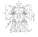
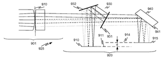
図3Aは、画像取込みユニット325Lおよび325Rと照明チャネル305とを含む立体視内視鏡302Aの遠位端部を示すブロック図である。各画像取込みユニット325R、325Lは、レンズ・アセンブリ301R、301L、およびセンサ・アセンブリ320R、320Lを含む。センサ・アセンブリ320R、320Lは、レンズ・アセンブリ301R、301Lを通過する光を受光するように位置決めされる。各画像取込みユニット320R、320Lは、1つの態様では、プリズム・アセンブリ330R、330L、反射アセンブリ340R、340L、および同一平面画像取込みセンサ(310R、315R)、(310L、315L)を含む。立体視内視鏡302Aは、立体視内視鏡202の一例である。
FIG. 3A is a block diagram illustrating the distal end of a stereoscopic endoscope 302A that includes image capture units 325L and 325R and an illumination channel 305. FIG. Each image capture unit 325R, 325L includes a lens assembly 301R, 301L and a sensor assembly 320R, 320L. The sensor assemblies 320R, 320L are positioned to receive light that passes through the lens assemblies 301R, 301L. Each image capture unit 320R, 320L includes, in one aspect,
図3Aに示すように、内視鏡302Aと呼ばれることもある立体視内視鏡302Aの遠位端部内の各立体視チャネルは、同じ要素構成を有する。この図3Aの態様では、画像取込みユニット325L(左の立体視チャネル)と画像取込みユニット325R(右の立体視チャネル)が、内視鏡302Aの中心線の長手方向軸線390と交差する平面に関して対称である(すなわち、互いに鏡像として位置決めされる)。矢印335が示すように、遠位方向は、組織303に向かう方向であり、近位方向は、組織303から離れる方向である。 As shown in FIG. 3A, each stereoscopic channel in the distal end of stereoscopic endoscope 302A, sometimes referred to as endoscope 302A, has the same component configuration. In the embodiment of FIG. 3A, image capture unit 325L (left stereoscopic channel) and image capture unit 325R (right stereoscopic channel) are symmetric with respect to a plane that intersects the longitudinal axis 390 of the centerline of endoscope 302A. (Ie, positioned as mirror images of each other). As arrow 335 indicates, the distal direction is toward tissue 303 and the proximal direction is away from tissue 303.
この例では、内視鏡302A内の1つまたは複数の照明チャネル305からの光が、組織303を照明する。図3Aには示していないが、内視鏡302Aの視野内の1つまたは複数の外科手術器具も、照明チャネル305からの光によって照明することができる。内視鏡内の照明チャネルを使用することは単なる例示であり、本明細書に示す様々な例に限定することを意図したものではない。照明は、内視鏡内の照明源によって行ってもよいし、内視鏡の内部または外部のその他の何らかの装置によって行ってもよい。 In this example, light from one or more illumination channels 305 in endoscope 302A illuminates tissue 303. Although not shown in FIG. 3A, one or more surgical instruments in the field of view of the endoscope 302A can also be illuminated by light from the illumination channel 305. The use of an illumination channel within an endoscope is merely exemplary and is not intended to be limited to the various examples shown herein. Illumination may be performed by an illumination source in the endoscope, or by some other device inside or outside the endoscope.
組織303で反射された光および任意の蛍光を、レンズ・アセンブリ301Lおよび301Rが受光する。レンズ・アセンブリ301Lおよび301R内のレンズ304Lおよび304Rは、それぞれ、受光した光をセンサ・アセンブリ320Lおよび320Rに向けて送る1つまたは複数の光学構成要素を含むことができる。他の態様では、レンズ・アセンブリ301Lおよび301Rを折り畳んで、画像取込みユニット325Lおよび325Rの長手方向長さを短縮する。 The lens assemblies 301L and 301R receive the light reflected from the tissue 303 and any fluorescence. The lenses 304L and 304R in the lens assemblies 301L and 301R can include one or more optical components that send received light toward the sensor assemblies 320L and 320R, respectively. In another aspect, the lens assemblies 301L and 301R are folded to reduce the longitudinal length of the image capture units 325L and 325R.
レンズ304L、304Rからの光は、それぞれセンサ・アセンブリ320L、320Rを通過する。センサ・アセンブリ320L、320R内では、この光を、プリズム・アセンブリ330L、330R内のビーム・スプリッタ331L、331Rが受光する。1つの態様では、各ビーム・スプリッタ331L、331Rは、埋め込まれたコーティング面331L、331Rとして実装される。以下でさらに完全に説明するように、各コーティング面331L、331Rの1層または複数層のコーティングは、特定の機能を実現するように選択される。コーティング面331L、331Rは、レンズ・アセンブリ301L、301Rが受光した光の第1の部分を反射し、この受光した光の第2の部分を透過させる。組織303のフィーチャを識別するために、コーティング面は、レンズ・アセンブリ301L、301Rから受光した光の偏光の違いを識別する。さらに他の態様では、コーティング面は、やはり受光した光の複数の部分を反射し、受光した光の他の部分を透過させるノッチ・フィルタを含む。
Light from lenses 304L and 304R passes through sensor assemblies 320L and 320R, respectively. In the sensor assemblies 320L and 320R, this light is received by the beam splitters 331L and 331R in the
コーティング面331L、331Rの実施態様に関わらず、ビーム・スプリッタ331Lは、受光した光の第1の部分を、例えば画像取込みセンサ310Lの表面311Lなど、画像取込みユニット325L内の第1の画像取込みセンサ310Lに向けて送り、この受光した光の第2の部分は、そのビーム・スプリッタ331Lを透過させる。同様に、ビーム・スプリッタ331Rは、受光した光の第1の部分を、例えば画像取込みセンサ310Rの表面311Rなど、画像取込みユニット325R内の第1の画像取込みセンサ310Rに向けて送り、この受光した光の第2の部分は、そのビーム・スプリッタ331Rを透過させる。 Regardless of the embodiment of the coating surfaces 331L, 331R, the beam splitter 331L can receive the first portion of the received light, eg, the first image capture sensor in the image capture unit 325L, such as the surface 311L of the image capture sensor 310L. The second part of the received light that is sent to 310L is transmitted through its beam splitter 331L. Similarly, the beam splitter 331R sends and receives the first portion of the received light toward the first image capture sensor 310R in the image capture unit 325R, such as the surface 311R of the image capture sensor 310R, for example. The second portion of light is transmitted through the beam splitter 331R.
図3Aの例では、ビーム・スプリッタ331Lおよび331Rを通過した光は、光学レンズ350Lおよび350Rがそれぞれ受光する。レンズ350Lおよび350Rは、受光した光を合焦させて画像取込みセンサ315Lおよび315Rまでの光路長を形成する。レンズ350Lおよび350Rは、必要に応じて設けられる。 In the example of FIG. 3A, the optical lenses 350L and 350R receive the light that has passed through the beam splitters 331L and 331R, respectively. Lenses 350L and 350R focus the received light to form an optical path length to image capture sensors 315L and 315R. The lenses 350L and 350R are provided as necessary.
レンズ350Lおよび350Rからの光は、反射アセンブリ340Lおよび340Rがそれぞれ受光する。反射ユニット340Lは、例えば受光した光を画像取込みセンサ315Lの面316Lに向けて送るなど、受光した光を画像取込みユニット325L内の第2の画像取込みセンサ315Lに向けて送る。同様に、反射ユニット340Rは、例えば受光した光を画像取込みセンサ315Rの面316Rに向けて送るなど、受光した光を画像取込みユニット325R内の第2の画像取込みセンサ315Rに向けて送る。本明細書に記載する各態様において、光は、画像取込みセンサの一表面に向けて送られるが、簡潔のために、これを「光は画像取込みセンサに向けて送られる」と言う。 Reflective assemblies 340L and 340R receive light from lenses 350L and 350R, respectively. The reflection unit 340L sends the received light toward the second image capture sensor 315L in the image capture unit 325L, for example, by sending the received light toward the surface 316L of the image capture sensor 315L. Similarly, the reflection unit 340R sends the received light toward the second image capture sensor 315R in the image capture unit 325R, such as sending the received light toward the surface 316R of the image capture sensor 315R. In each aspect described herein, light is directed toward one surface of the image capture sensor, but for the sake of brevity, this is referred to as “light is directed toward the image capture sensor”.
反射アセンブリ340L、340Rは、それぞれ、例えば鏡面など、受光した光を反射する反射面341L、341Rを含む。図3Aの例では、装置340Lおよび340Rはそれぞれ、1つの面が反射性コーティングを有するプリズムとして実装されるか、またはプリズムの斜辺の内部全反射を用いて実装される。1つの態様では、反射面341Rを含む平面と、画像取込みセンサ310Rの面311Rおよび画像取込みセンサ315Rの面316Rを含む平面とが交差して形成される角度θは45度であるので、このプリズムは、45度プリズムと呼ばれる。45度プリズムの面341Rは、面314Rの近傍の媒質が空気であるときには内部全反射を示すので、表面341Rは反射面と呼ばれる。 Each of the reflection assemblies 340L and 340R includes reflection surfaces 341L and 341R that reflect received light, such as a mirror surface. In the example of FIG. 3A, devices 340L and 340R are each implemented as a prism with one surface having a reflective coating, or with total internal reflection on the hypotenuse of the prism. In one aspect, the angle θ formed by the intersection of the plane including the reflective surface 341R and the plane including the surface 311R of the image capture sensor 310R and the surface 316R of the image capture sensor 315R is 45 degrees. Is called a 45 degree prism. Since the surface 341R of the 45 degree prism exhibits total internal reflection when the medium in the vicinity of the surface 314R is air, the surface 341R is called a reflecting surface.
画像取込みセンサ310Lおよび315Lは、同一平面である。すなわち、センサ上面311Lおよび316Lは、実質的に同じ平面内にある。センサ310Lおよび315Lの底面は、プラットフォーム312の第1の面によって規定される平面上にある。同様に、画像取込みセンサ310Rおよび315Rは、同一平面である。例えば、上面311Rおよび316Rは、実質的に同じ平面内にある。センサ310Rおよび315Rの底面は、プラットフォーム312の第2の面によって規定される平面上にある。プラットフォーム312は、例えば軸線390に沿って接合された2つのセラミック部品など、2つの平坦部品で構成することができる。プラットフォーム312の第1の面は、プラットフォーム312の第2の面と反対側の、第2の面から離間した表面である。 Image capture sensors 310L and 315L are coplanar. That is, the sensor top surfaces 311L and 316L are substantially in the same plane. The bottom surfaces of sensors 310L and 315L are on a plane defined by the first surface of platform 312. Similarly, image capture sensors 310R and 315R are coplanar. For example, the top surfaces 311R and 316R are in substantially the same plane. The bottom surfaces of sensors 310R and 315R are on a plane defined by the second surface of platform 312. The platform 312 can be composed of two flat parts, for example, two ceramic parts joined along an axis 390. The first surface of the platform 312 is a surface spaced from the second surface opposite the second surface of the platform 312.
1つの態様では、2つの画像取込みセンサ310R、315Rを含む第1の半導体ダイ317Rを、第1のセラミック・プラットフォーム上に取り付ける。2つの画像取込みセンサ310L、315Lを含む第2の半導体ダイ317Lを、第2のセラミック・プラットフォーム上に取り付ける。次いで、これら2つのセラミック・プラットフォームを接合して、プラットフォーム312を形成する。2つのダイ317R、317Lへのワイヤは、プラットフォーム312の1つまたは複数のチャネルを通過する。1つのダイで2つの画像取込みセンサを使用することは単なる例示であり、限定を目的としたものではない。いくつかの態様では、この2つの画像センサが、別々のダイの中にある(図9参照)。この2つの画像取込みセンサは、ダイ内の1つの大きな画像取込みセンサの一部とすることもでき、例えば画像取込みセンサ310Rと画像取込みセンサ315Rの間にあるその画像取込みセンサの画素は、無視される。 In one aspect, a first semiconductor die 317R that includes two image capture sensors 310R, 315R is mounted on a first ceramic platform. A second semiconductor die 317L containing two image capture sensors 310L, 315L is mounted on the second ceramic platform. These two ceramic platforms are then joined to form platform 312. Wires to the two dies 317R, 317L pass through one or more channels of the platform 312. The use of two image capture sensors on one die is merely exemplary and is not intended to be limiting. In some aspects, the two image sensors are in separate dies (see FIG. 9). The two image capture sensors can also be part of one large image capture sensor in the die, for example, that image capture sensor pixel between the image capture sensor 310R and the image capture sensor 315R is ignored. The
いくつかの態様では、プラットフォーム312を使用しなくてもよく、2組の画像取込みセンサを、電源ケーブル、制御ケーブルおよびビデオ・ケーブルへの必要な接続を行うように構成された1つの構造内に含める。また、図3Aに示すように1つの画像取込みユニット内で2つの同一平面の画像取込みセンサを使用することは、単なる例示であり、限定を目的としたものではない。例えば、いくつかの態様では、3つ以上の同一平面の画像取込みセンサを使用することもでき、例えば、複数のビーム・スプリッタを1列にして使用し、反射ユニットをその列の近位端部に配置することもできる。 In some aspects, the platform 312 may not be used, and the two sets of image capture sensors are in one structure configured to make the necessary connections to the power, control, and video cables. include. Also, the use of two coplanar image capture sensors within one image capture unit as shown in FIG. 3A is merely illustrative and not intended to be limiting. For example, in some aspects, more than two coplanar image capture sensors can be used, for example, using multiple beam splitters in a row and a reflective unit at the proximal end of the row. It can also be arranged.
画像取込みセンサを同一平面構成にすることにより、レンズのアーチファクトを補償するための較正、ならびに画像取込みセンサ310R/315R(第1の対)および310L/315L(第2の対)が取り込んだ異なる画像の再位置合わせが不要になる。上述のように、所与の対に含まれる2つの画像取込みセンサの空間的関係は一定であり、所与の対に含まれる2つの画像取込みセンサは共通のレンズ・アセンブリ、すなわち共通の前端部光学構造を共有しているので、これら2つの画像取込みセンサが取り込む1対の画像の空間的位置合わせは、時間が経っても一定であり、また焦点を変えるなど光学的条件を変化させる間も一定である。 Calibration to compensate for lens artifacts, and different images captured by image capture sensors 310R / 315R (first pair) and 310L / 315L (second pair) by co-planar image capture sensors No realignment is required. As described above, the spatial relationship between the two image capture sensors included in a given pair is constant, and the two image capture sensors included in a given pair have a common lens assembly, i.e., a common front end. Since the optical structure is shared, the spatial alignment of a pair of images captured by these two image capture sensors is constant over time and while changing optical conditions such as changing the focus. It is constant.
図3Bは、図3Aと同様であるが、内視鏡302Bがモノスコープ内視鏡であり、内視鏡302Bの外部にあって内視鏡302Bに接続されていない照明器によって照明が行われる点が異なる。ただし、いくつかの態様では、内視鏡302B上に照明器が取り付けられる。内視鏡302Bでは、画像取込みユニット325の要素301、304、320、330、331、340、341、350、310、311、315、316および312Bは、それぞれ要素301L、304L、320L、330L、331L、340L、341L、350L、310L、311L、315L、316Lおよび312と同じであるので、これらの要素について繰り返し説明することはしない。内視鏡外部の照明源は、記載する様々な内視鏡の実施形態において、内視鏡内部の照明チャネルまたは内視鏡に取り付けられた照明チャネルの代わりに、あるいはそれに加えて使用することができる。
FIG. 3B is similar to FIG. 3A, but the
図4Aは、レンズ・アセンブリ401Aおよびセンサ・アセンブリ420Aを含む画像取込みユニット425Aの一部を示す図である。センサ・アセンブリ420Aは、1つの態様では、プリズム・アセンブリ430A、反射ユニット440A、および同一平面の画像取込みセンサ410A、415Aを含む。レンズ・アセンブリ401Aは、遮蔽体470Aと呼ばれることもある光遮蔽体470Aを画定する光学素子など、複数の光学素子を含む。本明細書で用いる遮蔽体は、開口を有する空間内の平面または主光線の高さがゼロとなる光路中の位置である。遮蔽体470を通過した光は、画像取込みユニット425Aのプリズム・アセンブリ430A内のビーム・スプリッタ431Aによって受光される。
FIG. 4A shows a portion of an
立体視装置は、図4Aに示すように2つの画像取込みユニットを含むことになる。ただし、図3Aを参照して上記に示したように、画像取込みユニットを有する左右の立体視チャネルは対称であるので、説明の重複を避けるために、1つのチャネルおよび画像取込みユニットについてのみ説明する。画像取込みユニットを含むもう一方のチャネルは、図4Aに示すチャネルを有する内視鏡の長手方向軸線と交差する平面に関して対称である。 The stereoscopic device will include two image capture units as shown in FIG. 4A. However, as shown above with reference to FIG. 3A, the left and right stereoscopic channels with image capture units are symmetric, so only one channel and image capture unit will be described to avoid duplicate description. . The other channel containing the image capture unit is symmetric with respect to a plane intersecting the longitudinal axis of the endoscope having the channel shown in FIG. 4A.
ビーム・スプリッタ431Aは、遮蔽体470Aを通過する光を受光するように位置決めされる。ビーム・スプリッタ431Aは、受光した光の第1の部分を第1の画像取込みセンサ410Aに向けて送り、受光した光の第2の部分はビーム・スプリッタを通して反射ユニット440Aに送るように構成される。この例では、プリズム・アセンブリ430A内のビーム・スプリッタ431Aは、コーティングされた第1の面として実装される。したがって、ビーム・スプリッタ431Aは、コーティングされた第1の面431Aと呼ばれることもある。コーティングされた第1の面431Aは、受光した光を2つの部分に分離する。
コーティングされた第1の面431Aは、受光した光の第1の部分を第2の面432Aに向けて送り、第2の面432Aは、例えば反射するなどして、この光を第1の画像取込みセンサ410Aに向けて送る。コーティングされた第1の面431Aは、受光した光の第2の部分を、コーティングされた第1の面431Aを通過して反射ユニット440まで透過させる。1つの態様では、この光のコーティング面431Aへの入射角は、45度未満である。
The coated
第2の面432Aは、コーティングされた第1の面431Aによって反射された光以外の光が第2の面432Aに入射しないように位置決めされる。1つの態様では、第2の面432Aは、コーティング面および内部全反射面のうちの一方として実装される反射面である。
The
反射ユニット440Aは、ビーム・スプリッタ431Aから受光した光を第2の画像取込みセンサ415Aに反射する第3の面441Aを含む。1つの態様では、第3の面441Aは、例えばコーティング面および内部全反射面のうちの一方として実装される反射面である。
The
画像取込みセンサ410Aおよび415Aは、同一平面である。1つの態様では、遮蔽体470Aからコーティングされた第1の面431Aおよび第2の面432Aを経由して画像取込みセンサ410Aに至る第1の光路長は、遮蔽体470Aからコーティングされた第1の面431Aを通りコーティング面441Aを経由して画像取込みセンサ415Aに至る第2の光路長とほぼ等しい。別の態様では、第1の光路長と第2の光路長は等しくない。等しくない光路長は、以下にさらに完全に記載するように、反射ユニット内の表面とプリズム・アセンブリ内のビーム・スプリッタとの間の空間的関係を調節することによって実現することができる。
あるいは、画像取込みセンサ410Aは、センサ上面を第1の平面内に有し、画像取込みセンサ415Aは、センサ上面を第2の平面内に有し、第1の平面と第2の平面が平行であり、既知の距離だけ離間している(図9参照)。画像取込みセンサのこの代替構成では、2つの画像取込みセンサまでの光路長は、ほぼ等しくてもよいし、等しくなくてもよい。画像取込みセンサのセンサ上面は、センサ・アセンブリ内の少なくとも1つの光学構成要素から光を受光するその画像取込みセンサの面である。例えばセンサ415Aまでの第2の光路中で、レンズ350(図3参照)として示すように任意選択の光学素子を使用することもできる。
Alternatively, the
本明細書では、「ほぼ等しい」または「実質的に等しい」とは、2つの光路長が、様々な光路の要素の製造および取付けに関連する許容差の範囲内で等しいという意味である。また、遮蔽体470Aから始まる光路長の定義は例示であり、限定を目的としたものではない。光路長は、受光した光がプリズム・アセンブリ430Aに進入するプリズム・アセンブリ430Aの遠位面を基準にする、レンズ・アセンブリ内の最初の要素を基準にする、またはコーティングされた第1の面431Aを基準にするなど、様々に定義することができる。
As used herein, “substantially equal” or “substantially equal” means that the two optical path lengths are equal within tolerances associated with the manufacture and attachment of the elements of the various optical paths. Further, the definition of the optical path length starting from the
図4Aでは、プリズム・アセンブリ430A、反射ユニット440Aおよび画像取込みセンサ410A、415Aの離隔は一定の比率ではない。実際の使用に際しては、プリズム・アセンブリ430Aおよび反射ユニット440Aは、大抵固体のガラスであり、これらのガラス構造と画像取込みセンサ410A、415Aとの間には小さな隙間がある。図4Bは、プリズムを用いた図4Aの構造の実施態様の例である。
In FIG. 4A, the separation of
図4Bは、立体視内視鏡の遠位端部内の画像取込みユニット425Bを示す図である。画像取込みユニット425Bは、共有レンズ・アセンブリ401Bおよびセンサ・アセンブリ420Bを含む。センサ・アセンブリ420Bは、1つの態様では、プリズム・アセンブリ430B、反射ユニット440B、および同一平面の画像取込みセンサ410B、415Bを含む。センサ・アセンブリ420Bは、レンズ・アセンブリ401Bを通過する光を受光するように位置決めされる。もう一方の画像吐露込みユニット(図示せず)は、図4Bに示すものと等価な構成要素を含む。これら2つの画像吐露込みユニットは、図3Aに示すのと等価な形態で立体視内視鏡の長手方向軸線と交差する平面に関して対称である。
FIG. 4B shows an
組織によって反射された照明器からの光、または組織から生じた蛍光は、平面403Bで表される。この光は、窓481を通ってレンズ・アセンブリ401Bに入射し、次いで第1のレンズのセット482、プリズム483、第2のレンズのセット484、および遮蔽体を構成する開口素子470Bを通過する。
The light from the illuminator reflected by the tissue or the fluorescence generated from the tissue is represented by
要素485は必要に応じて設けられるものであり、様々な位置で様々なレンズ・アセンブリの実施形態に組み込むことができる様々なフィーチャを個々に、または組み合わせて例示するものである。1つの態様では、要素485は、蛍光励起波長を阻止するノッチ・フィルタの窓を表す。別の態様では、要素485は、合焦素子を表す。
別の態様では、要素485は、平面−平面(plano−plano)素子を表す。さらに別の態様では、要素485は、制御電圧が印加されたときに可変焦点レンズとして機能する液晶セルを含む構造を表す。制御電圧は、光が通過する物質の屈折率プロファイルを動的に変化させる。液晶セルは、良好な光学的性能で、焦点を無限大から10センチメートルまでの所望の焦点距離に調節することができる。これらの性能特性を有する液晶セルは、米国カリフォルニア州Mountain ViewのLensVector社からLens Vector(商標)AutoFocus素子として入手することができる(LENSVECTORは、米国のLensVector社の商標である)。
In another aspect,
いくつかの態様では、要素485は、レンズ・アセンブリ内のその他の要素が受光した光を前処理する1つまたは複数のフィルタを表す。あるいは、この1つまたは複数のフィルタは、内視鏡の遠位端部面に取り付けてもよいし、開口素子470Bとプリズム構造460との間に挿入してもよい。
In some aspects,
この態様では、プリズム構造460は、ビーム・スプリッタ431Bを備えるプリズム・アセンブリ430Bおよび反射面441Bを備える反射ユニット440Bを含む一体プリズム構造(2つ以上のプリズムが隙間なく接合されている)である。1つの態様では、プリズム構造460は、2つの画像取込みセンサへの所望の画像分離を実現するような特定の屈折率およびプリズム幾何形状を有する材料で設計される。プリズム構造460の設計は、多面プリズムから始めて、次いでセンサ間隔と、プリズムの幾何形状を制約する立体視内視鏡の所望の最大外側チューブ直径とに適応するように最適化する。
In this embodiment, the
図4Bに示す態様では、プリズム・アセンブリ430Bは、少なくとも2つのコーティング面431Bおよび432Bを有するペンタ(五角形)プリズムを含む。あるいは、表面432Bをコーティングせず、内部全反射を用いてもよい。ビーム・スプリッタすなわちコーティングされた第1の面431Bは、受光した光を2つの部分に分離する。コーティングされた第1の面431Bは、受光した光の第1の部分を第2の面432Bに反射し、この第2の面432Bが、この光を第1の画像取込みセンサ410Aに向けて送る、すなわち反射する。コーティングされた第1の面431Bは、受光した光の第2の部分を、面431Aを通過して反射ユニット440Bまで透過させる。プリズム450は、必要に応じて設けられるものであり、プリズム構造460の取扱いおよび取付けを容易にするために設けられる。
In the embodiment shown in FIG. 4B,
ペンタプリズムは、光ビームを90度偏向させるために使用される反射プリズムである。光ビームは、ペンタプリズム内部で2回反射され、これにより倒立像または逆転像を生じることなく光ビームを90度曲げて透過させることができる。通常は、ペンタプリズムは、5つの辺で構成された外周を有する。ペンタプリズムは、光路に対するペンタプリズムの配向に関わらず光路を同じ角度だけ偏向させるので、一定偏角プリズムである。本明細書では、ペンタプリズムは、その他のプリズムまたは光学素子に接着するなどして接合する、あるいはその他のプリズムまたは光学素子を基準として位置決めすることができる。 A pentaprism is a reflecting prism used to deflect a light beam by 90 degrees. The light beam is reflected twice inside the pentaprism so that the light beam can be bent 90 degrees and transmitted without producing an inverted or inverted image. Usually, a pentaprism has an outer periphery composed of five sides. The pentaprism is a constant deflection prism because it deflects the optical path by the same angle regardless of the orientation of the pentaprism relative to the optical path. In this specification, the pentaprism can be bonded to other prisms or optical elements, for example, or can be positioned with reference to the other prisms or optical elements.
1つの態様では、コーティングされた第1の面431Bは、多層埋込みコーティング面である。この面は、以下でさらに完全に述べるように、例えば多層ダイクロイック・コーティング、金属コーティングまたはひだ状(rugate)コーティングなど、所望の反射特性および透過特性を有する多層コーティングでコーティングされる。面431Bに対する光の入射角は、1つの態様では45度未満であるが、これは要件ではない。第2の面432Bは、コーティングされた第1の面431Bによって反射された光以外の光が第2の面432Bに入射しないように位置決めされる。
In one aspect, the coated
遠位面と呼ばれることもある遠位端部面433は、レンズ・アセンブリ401Bから受光した光が通過する、プリズム構造460およびプリズム・アセンブリ430Bの端部である。1つの態様では、第1の面431B、第2の面432Bおよび第3の面441Bは、遠位端部面433から画像取込みセンサ410Bまでの第1の光路長が、遠位端部面433から画像取込みセンサ415Bまでの第2の光路長とほぼ等しくなるように位置決めされる。別の態様では、面441Bは、この2つの光路長がわずかだけ異なるように位置決めされる。
1つの態様では、反射ユニット440Bが、反射コーティングを有する面441Bを含むプリズムであるか、または面441Bが、内部全反射による反射が可能になる角度で使用される。1つの態様では、反射面441Bを含む平面と画像取込みセンサ415Bのセンサ上面を含む平面とが交差して形成する角度は、45度であるので、このプリズムは45度プリズムと呼ばれる。この例では、プリズム構造460は、既知の技術を用いて3つの部品を接着することによって形成した一体構造である。前述のように、この3つの部品は、画像取込みセンサ410Bおよび415Bにおいて所望の画像分離をもたらすような材料、屈折率およびプリズム幾何形状で設計される。3つの部品を使用することは単なる例示であり、限定を目的としたものではない。例えば、プリズム構造460は、2つの部品を用いて形成した一体構造であってもよい。
In one aspect, the
画像取込みセンサ410Bおよび415Bは、同一平面にあり、1つの態様では、他方のレンズ・アセンブリの同一平面の画像センサも取り付けられているプラットフォーム上に取り付けられる(図3A参照)。いくつかの態様では、2つの画像取込みセンサが、1つの構造に含まれる。
遮蔽体470Bは、プリズム構造460の付近または内側に配置または形成して、プリズム構造460のサイズを小さくし、画像取込みセンサ410Bおよび415Bに対するコーナ線(corner rays)の入射角を小さくする。遮蔽体470Bは、要素485の遠位側(図示)に位置決めしても、近位側に位置決めしてもよい。
The
図4Bに示す例示的な態様では、レンズ・アセンブリ401B内の中央要素483は、プリズムとすることができる。いくつかの態様では、このプリズムは、例えば内視鏡の長手方向軸線に対して30度に配向された視野を有する内視鏡となるように屈曲光路を形成するように位置決めされる。この屈曲は、画像取込みセンサ410Bおよび415Bの平面に対して直交する平面内で起こる。
In the exemplary embodiment shown in FIG. 4B, the
図2、図3A、図3b、図4Aおよび図4Bを再度参照して、画像取込みユニットの様々な態様を示し、これらについて説明する。画像取込みユニットは、撮像対象の物体から光を受光するレンズ・アセンブリを含む。レンズ・アセンブリを通る前端部光路は、直線であってもよいし、あるいは屈曲させて様々な角度の付いた視野を内視鏡に持たせてもよい。レンズ・アセンブリからの光は、センサ・アセンブリまで進行する。様々な任意選択の光学構成要素(開口、フィルタ、合焦素子など)をレンズ・アセンブリ内に配置することもできるし、あるいは、設計制限が許せば、これらの光学構成要素を、センサ・アセンブリの1つまたは複数の光路内に挿入することもできる。 Referring again to FIGS. 2, 3A, 3b, 4A, and 4B, various aspects of the image capture unit are shown and described. The image capture unit includes a lens assembly that receives light from the object to be imaged. The front end optical path through the lens assembly may be straight or bent to provide the endoscope with various angled fields of view. Light from the lens assembly travels to the sensor assembly. Various optional optical components (apertures, filters, focusing elements, etc.) can be placed in the lens assembly or, if design constraints permit, these optical components can be attached to the sensor assembly. It can also be inserted into one or more optical paths.
1つの態様では、センサ・アセンブリは、2つ以上の同一平面の画像取込みセンサを含む。これらの同一平面の画像取込みセンサは、内視鏡の長さ方向に配列される。例えば、同一平面の画像取込みセンサが2つある場合には、これらの画像取込みセンサのうちの一方を、レンズ・アセンブリに比較的近接して(内視鏡の遠位端部側に)位置決めし、もう一方の画像取込みセンサを、レンズ・アセンブリから比較的離して(内視鏡の遠位端部から離間させて)位置決めする。このように、画像取込みセンサは、内視鏡の中心線の長手方向軸線にほぼ平行な平面内にある。1つの態様では、これらの画像取込みセンサが、両方とも、同じ半導体基板上の画像取込み領域(例えばCMOS画像取込み領域などであるが、あるいはCCD領域を使用してもよい)として形成される。したがって、この単一の基板は、少なくともその幅の約2倍の長さを有し、そのため、これらのセンサ領域は内視鏡内で長手方向に配列されるので、空間使用効率の観点から内視鏡内に位置決めすることができる。あるいは、画像取込みセンサは、上記の単一センサ基板構成と同様に、内視鏡内に配置された指示プラットフォームまたは基板上に、個別に形成し、位置決めすることもできる。 In one aspect, the sensor assembly includes two or more coplanar image capture sensors. These coplanar image capture sensors are arranged in the length direction of the endoscope. For example, if there are two coplanar image capture sensors, position one of these image capture sensors relatively close to the lens assembly (on the distal end of the endoscope). The other image capture sensor is positioned relatively far from the lens assembly (away from the distal end of the endoscope). Thus, the image capture sensor is in a plane that is substantially parallel to the longitudinal axis of the endoscope centerline. In one aspect, both of these image capture sensors are formed as image capture areas on the same semiconductor substrate (eg, a CMOS image capture area, or alternatively a CCD area may be used). Therefore, this single substrate has a length of at least about twice its width, and therefore these sensor regions are arranged longitudinally in the endoscope, so that from the point of view of space utilization efficiency, It can be positioned in the endoscope. Alternatively, the image capture sensors can be individually formed and positioned on a pointing platform or substrate disposed within the endoscope, similar to the single sensor substrate configuration described above.
センサ・アセンブリの内部では、レンズ・アセンブリから受光した光は、ビーム・スプリッタで2つ以上のビームに分割される。2つのセンサの実施態様では、例えば、これらのビームのうちの一方は、ビーム・スプリッタから、第1の画像取込みセンサに入射する一方の光路に沿って進行し、もう一方のビームは、第2の画像取込みセンサに入射する別の光路に沿って進行する。センサ・アセンブリ内のこれらの光路は、画像取込みセンサに入射した光がレンズ・アセンブリから受光した光に対してほぼ直交するように屈曲している。いくつかの態様では、センサ・アセンブリ内のこれらの光路は、レンズ・アセンブリがこれらの光学センサに取り込まれた画像にほぼ同じように影響を及ぼすように、ほぼ等しい長さになるように構成される。コーティング面または内部全反射面である反射面を様々に組み合わせて使用して、画像取込みアセンブリの光路の幾何形状を規定することができる。いくつかの態様では、プリズムを使用して、画像取込みセンサの反射面の位置合わせ要件を簡略化する。 Inside the sensor assembly, light received from the lens assembly is split into two or more beams by a beam splitter. In a two sensor embodiment, for example, one of these beams travels from a beam splitter along one optical path incident on a first image capture sensor and the other beam is a second beam. Travels along another optical path incident on the image capture sensor. These optical paths in the sensor assembly are bent so that the light incident on the image capture sensor is substantially orthogonal to the light received from the lens assembly. In some aspects, these optical paths in the sensor assemblies are configured to be approximately equal in length so that the lens assembly affects the images captured by these optical sensors in approximately the same way. The Various combinations of reflective surfaces that are coated surfaces or total internal reflection surfaces can be used to define the optical path geometry of the image capture assembly. In some aspects, prisms are used to simplify the alignment requirements of the reflective surface of the image capture sensor.
いくつかの態様では、1つの内視鏡内で使用される画像取込みユニットが1つであるので、内視鏡がモノスコープ機能を有する。しかし、他の態様では、1つの内視鏡内で2つの画像取込みユニットを使用して、立体視機能を実現する。一方の画像取込みユニットが左の立体視画像機能を実施し、他方の画像取込みユニットが右の立体視画像機能を実施する。いくつかの態様では、2つの画像取込みユニット内の画像取込みセンサは、これらセンサがほぼ内視鏡の中心に向くように背中合わせに配向される。このような構成では、2つの画像取込みユニットの前端部対物経路(objective path)が良好な立体視分離をもたらすように位置決めされ、かつ画像取込みセンサの回路を統合することができるので、内視鏡内の横方向の空間を効率的に使用することができる。いくつかの態様では、背中合わせの画像取込みセンサを、単一のプラットフォームまたは基板で支持して、さらに空間を節約し、光学的位置合わせをさらに良好にする(例えば、2つの画像取込みユニットを互いに位置合わせした後で内視鏡内に組み込むことができる)。背中合わせの画像取込みセンサは、ほぼ内視鏡の中心線の長手方向軸線に沿って位置決めすることができるが、いくつかの態様では、例えば場合によって使用されることもあるその他の遠位端部の内視鏡のフィーチャによって内視鏡の中心線の長手方向軸線からオフセットされることもある。あるいは、2つの画像取込みユニットは、同一面の画像取込みセンサが互いに向き合うように、または一方の画像取込みユニットの同一平面の画像取込みセンサが他方の画像取込みセンサの同一平面の画像取込みセンサと同一平面になるように(すなわち全ての画像取込みセンサが同一平面に(場合によっては同一基板上で同一平面に)なるように)、位置決めすることもできる。2つの画像取込みユニットの間の画像取込みセンサの平面の配向については、その他の様々な配向を使用することもできる。また、これらの1つまたは複数の画像取込みユニットは内視鏡の遠位端部にあるものとして概略的に述べたが、いくつかの態様では、これらの1つまたは複数の画像取込みユニットが内視鏡の近位端部にあってもよいことを理解されたい。 In some aspects, the endoscope has a monoscope function because only one image capture unit is used in one endoscope. However, in another aspect, the stereoscopic function is realized using two image capture units within one endoscope. One image capture unit performs the left stereoscopic image function and the other image capture unit performs the right stereoscopic image function. In some aspects, the image capture sensors in the two image capture units are oriented back-to-back so that the sensors are approximately toward the center of the endoscope. In such an arrangement, the front end objective path of the two image capture units can be positioned to provide good stereoscopic separation and the circuitry of the image capture sensor can be integrated. The lateral space in the inside can be used efficiently. In some aspects, back-to-back image capture sensors are supported on a single platform or substrate to further save space and improve optical alignment (e.g., two image capture units positioned relative to each other). Can be incorporated into the endoscope after being combined). The back-to-back image capture sensor can be positioned approximately along the longitudinal axis of the endoscope centerline, but in some aspects, for example, other distal end portions that may be used in some cases. The endoscope features may be offset from the longitudinal axis of the endoscope centerline. Alternatively, the two image capture units may be coplanar such that the same image capture sensors face each other, or the same image capture sensor of one image capture unit is coplanar with the same image capture sensor of the other image capture sensor. (I.e., all image capture sensors are in the same plane (in some cases on the same substrate)). Various other orientations may be used for the orientation of the plane of the image capture sensor between the two image capture units. Also, although these one or more image capture units have been described generally as being at the distal end of an endoscope, in some aspects these one or more image capture units are internal. It should be understood that it may be at the proximal end of the endoscope.
以下でさらに詳細に述べるように、この小型のデュアル撮像式画像取込みユニットの光学的幾何形状により、2つの比較的大きな画像センサを、所望の光学チャネルごとに内視鏡内に配置することができ、また入射光を2つ以上のビームに分割する画像取込みユニットのフィーチャにより、撮像システムを使用する人に対して数多くの異なる視覚表示機能を与えることができる。例えば、2つの画像取込みユニットを使用する場合には、一方の立体視画像のセットは第1の光ビームから取り込んだ特徴を有し、もう一方の立体視画像のセットは第2の光ビームから取り込んだ特徴を有する、2組の精密に位置合わせされた立体視画像のセットを取り込むことができる。 As described in more detail below, the optical geometry of this small dual image capture unit allows two relatively large image sensors to be placed in the endoscope for each desired optical channel. Also, the feature of the image capture unit that splits the incident light into two or more beams can provide many different visual display functions to the person using the imaging system. For example, when using two image capture units, one set of stereoscopic images has features captured from a first light beam, and the other set of stereoscopic images is derived from a second light beam. Two sets of precisely aligned sets of stereoscopic images having the captured features can be captured.
フィーチャ識別のエンハンス
外科手術部位のシーンの画像で時折生じる問題の1つに、執刀医用制御コンソール250で執刀医に対して提示される画像をエンハンスしようとしたときの飽和がある。1つの理由は、通常は視野内にある外科手術器具が組織より多くの光を反射することである。別の問題は、例えば神経や患部など、組織表面に直接的に存在していないようなシーン内の関心のあるフィーチャを識別することである。
Feature Identification Enhancement One of the problems that sometimes arises with images of surgical site scenes is saturation when trying to enhance the image presented to the surgeon in the surgeon's control console 250. One reason is that a surgical instrument, usually in the field of view, reflects more light than tissue. Another problem is identifying features of interest in the scene that do not exist directly on the tissue surface, such as nerves or affected areas.
1つの態様では、プリズム構造460および同一平面の画像410B、415Bを使用して照明が視野内の組織などの物体とどのように相互作用するかについての追加情報を集めることによって、シーンの撮像をエンハンスする。特に、照明光の偏光状態は、組織表面、組織内の表面下の構造、および外科手術器具によって様々に変動する。
In one aspect, imaging the scene by collecting additional information about how illumination interacts with objects such as tissue in the field of view using
エンハンスされたフィーチャ識別機能を照明側で実施する方法は、少なくとも2つある。照明は、偏光を優勢にすることも、非偏光を優勢にすることもできる。当業者には既知のように、光は完全に偏光することはないので、「偏光を優勢にする」とは、例えば理想的には1000:1など、識別するのに必要な程度まで偏光させることを意味する。ただし、コントラスト比がそれより低くても十分であることもある。同様に、「非偏光を優勢にする」とは、必要な程度まで非偏光にすることを意味する。 There are at least two ways to implement the enhanced feature identification function on the illumination side. Illumination can dominate polarized light or dominate non-polarized light. As known to those skilled in the art, light does not fully polarize, so “dominant polarization” is, for example, ideally polarized to the extent necessary to distinguish, such as 1000: 1. Means that. However, a lower contrast ratio may be sufficient. Similarly, “make non-polarized light dominant” means to make non-polarized light to the extent necessary.
フィーチャ識別のエンハンス(非偏光照明)
図5Aは、画像取込みユニット525Lおよび525Rならびに照明器からの非偏光光を供給する照明チャネル505を備える立体視内視鏡502Aの遠位端部を示す概略図である。矢印535が示すように、遠位方向は、組織503に向かう方向であり、近位方向は、組織503から離れる方向である。
Feature identification enhancement (unpolarized illumination)
FIG. 5A is a schematic diagram showing the distal end of a stereoscopic endoscope 502A with image capture units 525L and 525R and an illumination channel 505 that supplies unpolarized light from the illuminator. As arrow 535 indicates, the distal direction is the direction toward
各画像取込みユニット525R、525Lは、レンズ・アセンブリ501R、501L、およびセンサ・アセンブリ520R、520Lを含む。センサ・アセンブリ520R、520Lは、レンズ・アセンブリ501R、501Lを通過した光を受光するように位置決めされる。各センサ・アセンブリ520R、520Lは、1つの態様では、プリズム・アセンブリ530R、530L、反射ユニット540R、540L、および同一平面画像取込みセンサ(510R、515R)、(510L、515L)を含む。立体視内視鏡502Aは、内視鏡502Aと呼ばれることもある。 Each image capture unit 525R, 525L includes a lens assembly 501R, 501L and a sensor assembly 520R, 520L. The sensor assemblies 520R and 520L are positioned to receive light that has passed through the lens assemblies 501R and 501L. Each sensor assembly 520R, 520L, in one aspect, includes a prism assembly 530R, 530L, a reflective unit 540R, 540L, and coplanar image capture sensors (510R, 515R), (510L, 515L). The stereoscopic endoscope 502A may be referred to as an endoscope 502A.
照明チャネル505からの照明の一部は、組織503の表面で反射される。図5Aには示していないが、照明チャネル505からの照明の一部は、内視鏡502Aの視野内の外科手術器具によって反射されることもある。一部の組織は、それらの組織で反射された光にある程度の偏光を与える。
A portion of the illumination from illumination channel 505 is reflected at the surface of
以下の記述では、立体視内視鏡502Aの右チャネルの光路について述べる。内視鏡502の対称性により、立体視内視鏡502Aの左チャネルの光路は、右チャネルの光路と同じであるので、以下の記述では、左チャネルの参照番号を、右チャネルの要素の説明の後の括弧内に記載する。これは、その記述が左チャネルの対応する要素にも当てはまることを示している。 In the following description, the optical path of the right channel of the stereoscopic endoscope 502A will be described. Because of the symmetry of the endoscope 502, the left channel optical path of the stereoscopic endoscope 502A is the same as the right channel optical path, so in the following description, the left channel reference number is referred to as the right channel element description. In parentheses after. This indicates that the description also applies to the corresponding element of the left channel.
組織503からの偏光および非偏光の反射光は、レンズ・アセンブリ501R(501R)内のレンズ素子504R(504L)を通過して、遮蔽体570R(570L)に至る。レンズ・アセンブリ401B(図4B)内の要素は、レンズ素子504R(504L)の例である。この例では、任意選択の4分の1波長板580R(580L)が、遮蔽体570R(570L)と画像取込みユニット525R(525L)の遠位端部面との間の光路中に挿入される。別の態様(図示せず)では、4分の1波長板580R(580L)は、この光路に挿入されない。
Polarized and unpolarized reflected light from the
遮蔽体570R(570L)を通過する光は、センサ・アセンブリ520L(520R)によって受光され、ビーム・スプリッタ531R(531L)を含むプリズム・アセンブリ530R(530L)に進入する。ビーム・スプリッタ531R(531L)は、1つの態様では、偏光型ビーム・スプリッタである。ビーム・スプリッタ531R(531L)は、受光した光の偏光状態に基づいて受光した光の第1の部分を反射するように構成され、受光した光の偏光状態に基づいて受光した光の第2の部分を透過させるように構成される。1つの態様では、ビーム・スプリッタ531R(531L)は、コーティング面である。
Light passing through the
例えば、プリズム・アセンブリ530R(530L)に進入する非偏光光は、ビーム・スプリッタ531R(531L)によって第1の画像取込みセンサ510R(510L)と第2の画像取込みセンサ515R(515L)との間で均等に分割される。プリズム・アセンブリ530R(530L)に進入する直線偏光光は、その光の偏光と面531R(531L)のコーティングの配向の相対的な配向に応じて、ビーム・スプリッタ531R(531L)によって反射または透過される。直交する場合には、全ての偏光光が、第1の画像取込みセンサ510R(510L)または第2の画像取込みセンサ515R(515L)のいずれかに向けて送られる。1つの態様では、コーティング面531R(531L)に対する光の入射角は、45度未満である。 For example, unpolarized light entering the prism assembly 530R (530L) is transmitted by the beam splitter 531R (531L) between the first image capture sensor 510R (510L) and the second image capture sensor 515R (515L). Divided evenly. Linearly polarized light entering the prism assembly 530R (530L) is reflected or transmitted by the beam splitter 531R (531L) depending on the relative orientation of the polarization of the light and the orientation of the coating on the surface 531R (531L). The If orthogonal, all polarized light is sent to either the first image capture sensor 510R (510L) or the second image capture sensor 515R (515L). In one aspect, the incident angle of light with respect to the coating surface 531R (531L) is less than 45 degrees.
コーティングされた第1の面531R(531L)は、受光した光の第1の部分を第2の面532R(532L)に反射し、この第2の面532R(532L)が、この光を例えば反射するなどして、第1の画像取込みセンサ510R(510L)に向けて送る。第2の面532R(532L)は、コーティング面または内部全反射面のいずれかとすることができる。第2の面532R(532L)は、コーティングされた第1の面531R(531L)によって反射された光以外の光が第2の面532R(532L)に入射しないように位置決めされる。
The coated first surface 531R (531L) reflects the first portion of the received light to the
コーティングされた第1の面531R(531L)は、受光した光の第2の部分を面531R(531L)を通じて反射ユニット540R(540L)まで透過させる。具体的には、コーティング面を透過した光は、反射ユニット540R(540L)の第3の面541R(541L)によって受光され、この第3の面541R(541L)が、この光を例えば反射するなどして、第2の画像取込みセンサ515R(515L)に向けて送る。表面541R(541L)は、コーティング面または内部全反射面のいずれかとすることができる。 The coated first surface 531R (531L) transmits the second portion of the received light through the surface 531R (531L) to the reflection unit 540R (540L). Specifically, the light transmitted through the coating surface is received by the third surface 541R (541L) of the reflection unit 540R (540L), and the third surface 541R (541L) reflects this light, for example. Then, the image is sent to the second image capturing sensor 515R (515L). The surface 541R (541L) can be either a coating surface or an internal total reflection surface.
1つの態様では、プリズム・アセンブリ530R(530L)および反射ユニット540R(540L)が、プリズム構造に含まれる。この態様では、このプリズム構造は、以下にさらに完全に述べるように、埋込み多層偏光選択層を有する埋込みコーティング面431Bを含むプリズム構造460(図4B)と等価である。したがって、プリズム構造460に関する記述が、図5Aの態様で使用されるプリズム構造にも当てはまる。
In one aspect, prism assembly includes prism assembly 530R (530L) and reflection unit 540R (540L). In this aspect, the prism structure is equivalent to a prism structure 460 (FIG. 4B) that includes an embedded
コーティングされた第1の面531R(531L)は、例えば、埋込み多層偏光ビーム・スプリッタである。これらの層は、当業者には既知であり、偏光ビーム・スプリッタ・キューブとして一般的に使用されている。これらの誘電体膜型コーティングは、通常は埋込み型であり、1つの態様では、このようなコーティングを使用する。あるいは、偏光型ビーム・スプリッタは、米国ユタ州OremのMoxtek(登録商標)社や日本のポラテクノ社製の材料を用いてPBF02偏光ビーム・スプリッタとして構成することもできる(MOXTEKは、米国ユタ州OremのMoxtek(登録商標)社の米国登録商標)。 The coated first surface 531R (531L) is, for example, an embedded multilayer polarizing beam splitter. These layers are known to those skilled in the art and are commonly used as polarizing beam splitter cubes. These dielectric film type coatings are usually buried and in one embodiment, such coatings are used. Alternatively, the polarizing beam splitter can be configured as a PBF02 polarizing beam splitter using a material manufactured by Maxtek (registered trademark) of Orem, Utah, USA or Polatechno, Japan (MOXTEK, Orem, Utah, USA). (A registered trademark of Moxtek®).
画像取込みセンサ510R(510L)および515R(515L)は、同一平面にある。1つの態様では、遮蔽体570R(570L)からコーティングされた第1の面531R(531L)および第2の面532R(532L)を経由して画像取込みセンサ510R(510L)に至る第1の光路長は、遮蔽体570R(570L)からコーティングされた第1の面531R(531L)および第3の面541R(541L)を経由して画像取込みセンサ515R(515L)に至る第2の光路長とほぼ等しい。また、遮蔽体570R(570L)から始まる光路長の定義は例示であり、限定を目的としたものではない。光路長は、受光した光がプリズム・アセンブリ530R(530L)に進入するプリズム・アセンブリ530R(530L)の遠位面を基準にする、レンズ・アセンブリ501R(501L)内の最初の要素を基準にする、またはコーティングされた第1の面531R(531L)を基準にするなど、様々に定義することができる。
Image capture sensors 510R (510L) and 515R (515L) are in the same plane. In one embodiment, the first optical path length from the
同一平面の画像取込みセンサ510R(510L)および515R(515L)は、レンズ・アセンブリ501R(501L)内の前端部光学構造を通る光路長は共通であり、センサ・アセンブリ520R(520L)内の各画像取込みセンサまでの光路長はほぼ同じである。一方の画像取込みセンサ510R(510L)は、偏光ビーム・スプリッタ531R(531L)によって反射された光で構成された画像を取り込む。他方の画像取込みセンサ515R(515L)は、偏光ビーム・スプリッタ531R(531L)を透過した光で構成された画像を取り込む。 The coplanar image capture sensors 510R (510L) and 515R (515L) have a common optical path length through the front end optics in the lens assembly 501R (501L) and each image in the sensor assembly 520R (520L). The optical path length to the acquisition sensor is almost the same. One image capture sensor 510R (510L) captures an image composed of the light reflected by the polarization beam splitter 531R (531L). The other image capturing sensor 515R (515L) captures an image composed of light transmitted through the polarization beam splitter 531R (531L).
画像取込みユニット525R(525L)は、2つの偏光状態(直交直線状態、または4分の1波長板580R(580L)を用いた左右の円偏光状態)を撮像する。この場合には、画像取込みユニット525R(525L)が取得する画像は、組織自体の構造によって与えられる優先偏光に基づいて情報を提供する。画像取込みユニット525R(525L)は、受光した光の偏光状態の2つの直交成分の相対強度を取り込むことしかできない(光の偏光の性質全てではない)。しかし、有用な情報を得るには、これで十分である。 The image capturing unit 525R (525L) images two polarization states (orthogonal linear state or left and right circular polarization states using the quarter-wave plate 580R (580L)). In this case, the image acquired by the image capture unit 525R (525L) provides information based on the preferential polarization given by the structure of the tissue itself. The image capture unit 525R (525L) can only capture the relative intensities of the two orthogonal components of the polarization state of the received light (not all the properties of light polarization). However, this is sufficient to obtain useful information.
例えば、光は、表面によって鏡面反射されるときに優先的に偏光される。偏光の程度(および偏向の状態)は、照明の角度および表面の反射特性によって決まる。 For example, light is preferentially polarized when it is specularly reflected by the surface. The degree of polarization (and the state of deflection) depends on the angle of illumination and the reflective properties of the surface.
臨床の状況では、これにより、一部の鏡面反射を減少させることができる。画像取込みユニット525R(525L)に進入する反射光は、直線偏光に基づいて分離され、2つの画像が取り込まれる。取り込んだ画像内における光る器具による反射は、一方の取込み画像には出現するが、他方の取込み画像には出現しないので、ソフトウェアを実行することによって識別して減少させることができる。このプロセスは、光る器具によって反射された光が部分偏光であるためにうまくいく。このプロセスにより、立体視ディスプレイ251上で執刀医に対して提示される画像では、鏡面反射が減少する。
In the clinical situation, this can reduce some specular reflections. The reflected light entering the image capturing unit 525R (525L) is separated based on the linearly polarized light, and two images are captured. Reflections by the shining instrument in the captured image appear in one captured image but not in the other captured image and can be identified and reduced by running software. This process works well because the light reflected by the luminaire is partially polarized. This process reduces specular reflections in images presented to the surgeon on the
1つの態様では、デュアル画像エンハンス・モジュール240R(240L)(図2)が、画像取込みセンサ510R(510L)および515R(515L)(図5A)が取り込んだ画像を処理して、外科手術器具による反射を減少させる。例えば第2の画像内の画素値の何割かを第1の画像内の対応する画素値から減算するなど、画像取込みセンサ515R(515L)によって取り込まれた第2の画像内の画素からの情報を使用して画像取込みセンサ510R(510L)によって取り込まれた第1の画像内の画素を修正して、外科手術器具を表す画素の輝度をさらに低下させる。1つの態様では、この割合は、経験的に決定される。これは、2つの画像が同じ前端部光学構造を有し、空間的および時間的に互いに対して位置合わせされているために行うことができる。 In one aspect, dual image enhancement module 240R (240L) (FIG. 2) processes the images captured by image capture sensors 510R (510L) and 515R (515L) (FIG. 5A) for reflection by the surgical instrument. Decrease. Information from the pixels in the second image captured by the image capture sensor 515R (515L), for example, subtracting some of the pixel values in the second image from the corresponding pixel values in the first image. Use to modify pixels in the first image captured by the image capture sensor 510R (510L) to further reduce the brightness of the pixels representing the surgical instrument. In one aspect, this ratio is determined empirically. This can be done because the two images have the same front end optics and are aligned with respect to each other in space and time.
さらに、一部の組織は、その組織が反射した光にある程度の偏光を与える。例えば、長い繊維質の組織は、反射光に偏光を与えることがある。この態様では、デュアル画像エンハンス・モジュール240R(240L)(図2)は、画像取込みセンサ515R(515L)が、受光した偏光光から取り込んだ第2の画像の画素を処理し、例えば画素に着色することができる。次いで、着色された画像を、画像取込みセンサ510R(510L)からの第1の画像と結合し、この結合した画像を、立体視ディスプレイ251に送信して、執刀医が見られるようにする。この状況では、「着色」は、それにより関心のある特定の画素を背景より視覚的に顕著にすることができるので、好ましいことである。
In addition, some tissues impart some degree of polarization to the light reflected by the tissue. For example, a long fibrous tissue may polarize the reflected light. In this aspect, the dual image enhancement module 240R (240L) (FIG. 2) processes the pixels of the second image captured by the image capture sensor 515R (515L) from the received polarized light, for example, coloring the pixels. be able to. The colored image is then combined with the first image from the image capture sensor 510R (510L) and the combined image is sent to the
これに加えて、またはその別法として、デュアル画像エンハンス・モジュール240R(240L)(図2)は、画像取込みセンサ515R(515L)が、受光した偏光光から取り込んだ第2の画像の画素を処理し、その後、画像取込みセンサ510R(510L)が取り込んだ第1の画像の対応する画素を決定する。デュアル画像エンハンス・モジュール240R(240L)は、例えば透明度を上げるなど、第1の画像の対応する画素の性質を変化させ、その後、第1の画像と第2の画像とを結合する。結合した画像は、立体視ディスプレイ251に送信され、執刀医が見られるようにする。入射光を偏光させない組織の方が透明度が高いので、これにより、執刀医は、入射光を偏光させた組織をより明確に識別することができるようになるので、組織を識別するための追加の手掛かりが得られる。このように、デュアル画像エンハンス・モジュール240R(240L)によって生成された結合画像では、受光した光の偏光の違いに基づいて画像のフィーチャの顕著性が高められており、例えば上に重なる組織の透明度を上げ、その他の鏡面反射を減少させることによって、そのフィーチャを見えやすくしている。
In addition, or alternatively, the dual image enhancement module 240R (240L) (FIG. 2) allows the image capture sensor 515R (515L) to process the pixels of the second image captured from the received polarized light. Thereafter, the corresponding pixels of the first image captured by the image capture sensor 510R (510L) are determined. The dual image enhancement module 240R (240L) changes the nature of the corresponding pixel of the first image, for example, increases transparency, and then combines the first image and the second image. The combined image is sent to the
画像取込みユニットの画像取込みセンサは同一平面であるので、2つの画像取込みユニット内の画像取込みセンサのセットは、互いに固定された一定の関係にある。また、各画像取込みユニットのレンズ・アセンブリは同じである。したがって、様々な画像を処理して、執刀医の見ている画像が整列されて適切な立体視画像を形成するようにするときに、積極的な位置合わせを行う必要がない。このため、これらの特徴を用いずに取り込まれた画像より、画像に必要な処理が減少する。 Since the image capture sensors of the image capture units are coplanar, the sets of image capture sensors in the two image capture units are in a fixed relationship with each other. The lens assembly of each image capture unit is the same. Therefore, it is not necessary to perform positive alignment when processing various images so that the images viewed by the surgeon are aligned to form an appropriate stereoscopic image. For this reason, the processing required for the image is reduced as compared with an image captured without using these features.
フィーチャ識別のエンハンス(偏光照明)
図5Bは、画像取込みユニット525Rおよび525Lならびに照明器からの光を供給する照明チャネル505を備える立体視内視鏡502Bの遠位端部を示す概略図である。矢印535が示すように、遠位方向は、組織503に向かう方向であり、近位方向は、組織503から離れる方向である。
Feature identification enhancement (polarized illumination)
FIG. 5B is a schematic diagram illustrating the distal end of a stereoscopic endoscope 502B with image capture units 525R and 525L and an illumination channel 505 that supplies light from the illuminator. As arrow 535 indicates, the distal direction is the direction toward
各画像取込みユニット525R、525Lは、レンズ・アセンブリ501R、501L、およびセンサ・アセンブリ520R、520Lを含む。センサ・アセンブリ520R、520Lは、レンズ・アセンブリ501R、501Lを通過した光を受光するように位置決めされる。各センサ・アセンブリ520R、520Lは、1つの態様では、プリズム・アセンブリ530R、530L、反射ユニット540R、540L、および同一平面画像取込みセンサ(510R、515R)、(510L、515L)を含む。また、立体視内視鏡502Aは、内視鏡502Aと呼ばれることもある。 Each image capture unit 525R, 525L includes a lens assembly 501R, 501L and a sensor assembly 520R, 520L. The sensor assemblies 520R and 520L are positioned to receive light that has passed through the lens assemblies 501R and 501L. Each sensor assembly 520R, 520L, in one aspect, includes a prism assembly 530R, 530L, a reflective unit 540R, 540L, and coplanar image capture sensors (510R, 515R), (510L, 515L). Further, the stereoscopic endoscope 502A may be referred to as an endoscope 502A.
照明を偏光させる偏光器581は、照明光路長の中に設けられる。図5Bでは、偏光器581は、立体視内視鏡502Aの遠位端部に示してあるが、これは単なる例示であり、この位置に限定するものではない。偏光器581は、照明の経路中の偏光器を代表して表すものであり、その経路中の適当な位置に配置することができる。あるいは、照明チャネル505は、偏光源からの光を送ることもできるし、あるいは偏光光源を位置581に配置してもよい。 A polarizer 581 that polarizes illumination is provided in the illumination optical path length. In FIG. 5B, the polarizer 581 is shown at the distal end of the stereoscopic endoscope 502A, but this is merely exemplary and is not limited to this position. The polarizer 581 represents the polarizer in the illumination path, and can be disposed at an appropriate position in the path. Alternatively, illumination channel 505 can transmit light from a polarized light source, or a polarized light source can be placed at location 581.
以下の記述では、立体視内視鏡502Bの右チャネルの光路について述べる。立体視内視鏡502Bの左チャネルの光路は、右チャネルの光路と同じであるので、以下の記述では、左チャネルの参照番号を、右チャネルの要素の説明の後の括弧内に記載する。これは、その記述が左チャネルの対応する要素にも当てはまることを示している。 In the following description, the optical path of the right channel of the stereoscopic endoscope 502B will be described. Since the optical path of the left channel of the stereoscopic endoscope 502B is the same as the optical path of the right channel, in the following description, the reference number of the left channel is described in parentheses after the description of the elements of the right channel. This indicates that the description also applies to the corresponding element of the left channel.
組織503からの偏光および非偏光の光は、レンズ素子504R(504L)および遮蔽体570R(570L)を通過する。この場合も、レンズ・アセンブリ401B(図4B)内の要素は、レンズ素子504R(504L)の例である。この例では、遮蔽体570R(570L)とセンサ・アセンブリ520R(520L)の遠位端部面との間の任意選択の4分の1波長板580R(580L)(図5A)が、取り外されている。しかし、以下に述べるその他の態様では、4分の1波長板がレンズ・アセンブリに含まれている。
Polarized and unpolarized light from the
遮蔽体570R(570L)を通過する光は、センサ・アセンブリ520L(520R)によって受光され、遠位面を通ってプリズム・アセンブリ530R(530L)に進入する。上述のように、プリズム・アセンブリ530R(530L)の偏光ビーム・スプリッタ531R(531L)は、受光した光の偏光状態に基づいて受光した光の第1の部分を反射するように構成され、受光した光の偏光状態に基づいて受光した光の第2の部分を透過させるように構成される。
Light passing through the
この例では、偏光ビーム・スプリッタ531R(531L)は、1つの偏光状態で第1の画像取込みセンサ510R(510L)に向けるように構成され、残りの光を、例えば反射ユニット540R(540L)に送るなどして、反射ユニット540R(540L)まで透過させるように構成され、この反射ユニット540R(540L)が、その透過光を画像取込みセンサ515R(515L)に向けて送る。したがって、プリズム・アセンブリ530R(530L)、偏光ビーム・スプリッタ531R(531L)、反射ユニット540R(540L)ならびに画像取込みセンサ515R(510L)および515R(515L)について繰り返し説明することはせず、図5Aに関する上記の説明を、参照により本明細書に組み込む。 In this example, the polarizing beam splitter 531R (531L) is configured to be directed to the first image capture sensor 510R (510L) in one polarization state and send the remaining light to, for example, the reflection unit 540R (540L). The reflection unit 540R (540L) transmits the transmitted light toward the image capturing sensor 515R (515L). Accordingly, the prism assembly 530R (530L), the polarizing beam splitter 531R (531L), the reflection unit 540R (540L) and the image capture sensors 515R (510L) and 515R (515L) will not be described repeatedly, but with respect to FIG. 5A. The above description is incorporated herein by reference.
偏光器581からの偏光照明の一部は、組織503の表面で反射される。この表面で反射された光は、偏光照明とほぼ同じ偏光を有する。例えば、上面反射は、依然として、組織503に入射する光の元の偏光状態の大部分を占めている。
Part of the polarized illumination from the polarizer 581 is reflected at the surface of the
この表面で反射されない光は組織503に進入し、組織503の表面より下にある入射光の偏光を修正するフィーチャ503−1から503−4と相互作用する。組織503に進入する光は、散乱または吸収される。散乱光の一部は、組織503の表面から出て、レンズ素子504R(504L)において反射光のように見える。したがって、組織503から出る光の一部は、偏光の変化により、取り込んだ画像に追加の情報を与える。したがって、偏光光によって照明して、偏光感知検出器を用いて撮像するときには、例えば偏光解消された光など、照明の偏光と異なる偏光を有する光は、組織503の表面下のものと相互作用しているに違いないということになる。
Light that is not reflected by this surface enters
例えば、照明が直線偏光である場合には、その光は、組織503の表面下フィーチャ503−1から503−4に進入してそこから反射されるときに次第に偏光解消される。表面下フィーチャ503−1から503−4からの反射光は、基本的に偏光解消される。
For example, if the illumination is linearly polarized, the light is progressively depolarized as it enters and is reflected from subsurface features 503-1 to 503-4 of
したがって、偏光器581およびコーティングされた第1の面531R(531L)を適切に配向すれば、画像取込みセンサ515R(515L)は、主に組織503の表面によって反射された光および表面下フィーチャ503−1から503−4からの光の約50パーセントから、画像を取り込む。画像取込みセンサ515R(515L)は、表面下フィーチャ503−1から503−4によって主として反射された光から画像を取り込み、表面503からの光はそれほど取り込まない。センサ・アセンブリ520R(520L)は、受光した光の偏光状態の2つの直交成分の相対強度を取り込むことしかできない(光の偏光の性質全てではない)。しかし、有用な情報を得るには、これで十分である。
Accordingly, with proper orientation of the polarizer 581 and the coated first surface 531R (531L), the image capture sensor 515R (515L) is primarily responsible for the light reflected by the surface of the
特に、偏光照明を偏光感知撮像と併用すると、撮像プロセス中に組織の表面層を選択的に弱めることができる。この態様では、デュアル画像エンハンス・モジュール240R(240L)(図2)は、画像取込みセンサ510R(510L)が、受光した光から取り込んだ第1の画像の画素を処理し、その後、画像取込みセンサ515R(515L)が取り込んだ第2の画像の対応する画素を決定する。デュアル画像エンハンス・モジュール240R(240L)は、ユーザ・インタフェース262からの入力の制御下で、立体視ディスプレイ251に表示されるものを調節することができる。例えば、表面503だけを見るには、画像エンハンス・モジュール240R(240L)は、画像取込みセンサ515R(515L)が取り込んだ画像から画像取込みセンサ510R(510L)が取り込んだ画像を減算する。その結果得られた画像を立体視ディスプレイ251に送信して、執刀医が見られるようにする。あるいは、ユーザ・インタフェース262からの入力に応答して表面下フィーチャ503−1から503−4を示すには、画像エンハンス・モジュール240R(240L)は、画像取込みセンサ510R(510L)が取り込んだ画像をスケーリングして、立体視ディスプレイ251に表示されている画像と同様の輝度を実現する。その結果得られた画像を立体視ディスプレイ251に送信して、執刀医が見られるようにする。
In particular, when polarized illumination is used in conjunction with polarization sensitive imaging, the tissue surface layer can be selectively weakened during the imaging process. In this aspect, the dual image enhancement module 240R (240L) (FIG. 2) processes the first image pixels captured by the image capture sensor 510R (510L) from the received light, and then the image capture sensor 515R. (515L) determines the corresponding pixel of the second image captured. The dual image enhancement module 240R (240L) can adjust what is displayed on the
入射光の偏光を変化させない表面組織の透明度が上がっているので、これにより、執刀医は、入射光の偏光を変化させた表面下フィーチャをより明確に識別することができるようになり、組織を識別するための追加の手掛かりが得られる。このように、デュアル画像エンハンス・モジュール240R(240L)によって生成されたエンハンス画像では、受光した光の偏光の違いに基づいて画像のフィーチャの顕著性が高められている。 This increases the transparency of the surface tissue that does not change the polarization of the incident light, which allows the surgeon to more clearly identify subsurface features that have changed the polarization of the incident light, Additional clues are obtained for identification. In this way, in the enhanced image generated by the dual image enhancement module 240R (240L), the saliency of the image features is enhanced based on the difference in polarization of the received light.
さらに、照明が円偏光の場合には、組織503の上面からの反射が、偏光の左右像が反転した状態で起こる。センサ・アセンブリ520R(520L)において、反射光が4分の1波長板(図5Aの4分の1波長板580R参照)に進入した後に直線偏光に基づいて分離された場合には、上面反射は大幅に減少し、光る道具からの反射も減少する。表面下組織層は依然として次第に光を偏光解消するので、表面層は以前より透明に見えるように執刀医に対して提示することができる。これにより、組織の層、組織の種類、または組織503の表面下に現れる病気の状態をより良好に識別することができるようになる。このようにして、執刀医は、上述のように、最上層の透明度を上げ、鏡面反射を減少させることによって、最上層からの反射を抑制することができるので、組織503の上面を選択的に「透かして」見ることができる。さらに、上述のように、組織503の上面だけを見ることもできる。
Further, when the illumination is circularly polarized light, reflection from the upper surface of the
この技術によって強調することができる組織フィーチャの例としては、子宮内膜症などが挙げられる。また、この技術は、偏光サインを有する神経を識別する機能を強化することもできる。このように、様々な臨床の状況で、デュアル画像エンハンス・モジュール240R(240L)によって生成した結合画像では、受光した光の偏光の違いに基づいて画像のフィーチャの顕著性が高められている。 Examples of tissue features that can be emphasized by this technique include endometriosis and the like. This technique can also enhance the ability to identify nerves with polarization signatures. Thus, in various clinical situations, the combined image generated by the dual image enhancement module 240R (240L) has enhanced image feature saliency based on the difference in polarization of the received light.
解像度およびダイナミック・レンジのエンハンス
内視鏡の遠位端部に従来技術のカメラを配置しても立体視カラー画像は得られるが、これらのカメラは、各立体視チャネルで画像をとらえる1つのCCDが提供する解像度およびダイナミック・レンジに制限される。立体視内視鏡の従来のカメラと同様に、解像度は、CCDの画素数およびカラー・フィルタ・アレイによって制限される。立体視内視鏡の遠位端部では利用できる空間が制限されていることを考えると、CCDの画素数を増やすことは実用的ではないので、解像度をさらに上げることは実用的ではなかった。
Resolution and dynamic range enhancement Although a prior art camera can be placed at the distal end of an endoscope to produce a stereoscopic color image, these cameras have a single CCD that captures the image in each stereoscopic channel. Limited to the resolution and dynamic range offered by. As with conventional cameras in stereoscopic endoscopes, the resolution is limited by the number of pixels in the CCD and the color filter array. Considering that the space available at the distal end of the stereoscopic endoscope is limited, it is not practical to increase the number of pixels of the CCD, so it is not practical to further increase the resolution.
同様に、外科手術部位のシーンの中心は、通常はそのシーンの周辺部よりはるかに明るい。これにより、取り込まれた画像の輝度の範囲がCCDのダイナミック・レンジを超えると、取り込まれた画像(の強度)がクリッピングされる可能性がある。画像取込みユニット625Rおよび625L(図6A)は、以下でさらに完全に述べるように、さらに高い見かけの解像度およびさらに高いダイナミック・レンジの両方を提供することにより、これらの従来技術の問題を解消する。 Similarly, the center of the scene at the surgical site is usually much brighter than the periphery of the scene. As a result, if the luminance range of the captured image exceeds the dynamic range of the CCD, the captured image (its intensity) may be clipped. Image capture units 625R and 625L (FIG. 6A) eliminate these prior art problems by providing both higher apparent resolution and higher dynamic range, as described more fully below.
図6Aは、画像取込みユニット625Lおよび625Rならびに照明器からの光を供給する照明チャネル505を備える立体視内視鏡602の遠位端部を示す概略図である。矢印635が示すように、遠位方向は、組織603に向かう方向であり、近位方向は、組織603から離れる方向である。 FIG. 6A is a schematic diagram showing the distal end of a stereoscopic endoscope 602 with image capture units 625L and 625R and an illumination channel 505 that supplies light from the illuminator. As arrow 635 indicates, the distal direction is toward tissue 603 and the proximal direction is away from tissue 603.
各画像取込みユニット625R、625Lは、レンズ・アセンブリ601R、601L、およびセンサ・アセンブリ620R、620Lを含む。センサ・アセンブリ620R、620Lは、レンズ・アセンブリ601R、601Lを通過した光を受光するように位置決めされる。各センサ・アセンブリ620R、620Lは、1つの態様では、プリズム・アセンブリ630R、630L、反射ユニット640R、640L、および同一平面画像取込みセンサ(610R、615R)、(610L、615L)を含む。立体視内視鏡602は、内視鏡602と呼ばれることもある。 Each image capture unit 625R, 625L includes a lens assembly 601R, 601L and a sensor assembly 620R, 620L. Sensor assemblies 620R, 620L are positioned to receive light that has passed through lens assemblies 601R, 601L. Each sensor assembly 620R, 620L, in one aspect, includes a prism assembly 630R, 630L, a reflection unit 640R, 640L, and a coplanar image capture sensor (610R, 615R), (610L, 615L). The stereoscopic endoscope 602 may be referred to as an endoscope 602.
以下の記述では、立体視内視鏡602の右チャネルの光路について述べる。内視鏡602の対称性により、立体視内視鏡602の左チャネルの光路は、右チャネルの光路と同じであるので、以下の記述では、左チャネルの参照番号を、右チャネルの要素の説明の後の括弧内に記載する。これは、その記述が左チャネルの対応する要素にも当てはまることを示している。また、図6Aでは、図5Aおよび図5Bに示す要素と同じ参照番号を有する要素は、図5Aおよび図5Bに関連して上述した要素と同じまたは等価な要素である。繰り返しを避けるために、同じ参照番号を有する要素について、図6Aで再度述べることはしない。 In the following description, the optical path of the right channel of the stereoscopic endoscope 602 will be described. Due to the symmetry of the endoscope 602, the optical path of the left channel of the stereoscopic endoscope 602 is the same as the optical path of the right channel. In parentheses after. This indicates that the description also applies to the corresponding element of the left channel. Also, in FIG. 6A, elements having the same reference numbers as those shown in FIGS. 5A and 5B are the same or equivalent elements as those described above with reference to FIGS. 5A and 5B. To avoid repetition, elements having the same reference numbers are not described again in FIG. 6A.
組織503からの光は、レンズ・アセンブリ501R(501L)内のレンズ素子504R(504L)および遮蔽体570R(570L)を通過する。レンズ・アセンブリ401B(図4B)内の要素は、レンズ素子504R(504L)の例である。センサ・アセンブリ620L(620R)によって受光された光は、プリズム・アセンブリ630に進入する。プリズム・アセンブリ630R(630L)は、プリズム・アセンブリ630R(630L)が受光した光の第1の割合を反射し、受光した光の第2の割合を反射ユニット540R(540L)まで通過させる、例えばコーティングされた第1の面などのビーム・スプリッタ631R(631L)を含む。
Light from
コーティングされた第1の面631R(631L)によって反射された光は、第2の面632R(632L)によって受光され、第2の面632R(632L)は、この光を、例えば反射するなどして、第1の画像取込みセンサ610R(610L)に向けて送る。第2の面632R(632L)は、例えば、コーティング面および内部全反射面のうちの1つである。コーティングされた第1の面631R(631L)を透過した光は、反射ユニット540R(540L)の第3の面541R(541L)によって受光され、第3の面541R(541L)は、この光を反射するなどして、第2の画像取込みセンサ615R(615L)に向けて送る。 The light reflected by the coated first surface 631R (631L) is received by the second surface 632R (632L), and the second surface 632R (632L) reflects this light, for example. , And sent toward the first image capture sensor 610R (610L). The second surface 632R (632L) is, for example, one of a coating surface and an internal total reflection surface. The light transmitted through the coated first surface 631R (631L) is received by the third surface 541R (541L) of the reflection unit 540R (540L), and the third surface 541R (541L) reflects this light. For example, the image is sent to the second image capture sensor 615R (615L).
第2の面632R(632L)は、コーティングされた第1の面631R(631L)によって反射された光以外の光が第2の面632R(632L)に入射しないように位置決めされる。1つの態様では、コーティング面631R(631L)に対する光の入射角は、45度未満である。 The second surface 632R (632L) is positioned so that light other than the light reflected by the coated first surface 631R (631L) does not enter the second surface 632R (632L). In one aspect, the incident angle of light with respect to the coating surface 631R (631L) is less than 45 degrees.
1つの態様では、プリズム・アセンブリ630R(630L)および反射ユニット540R(540L)は、プリズム・アセンブリ630R(630L)を含むペンタプリズムを有するプリズム構造に含まれる。この態様のプリズム構造は、受光した光の第1の割合を反射し、受光した光の第2の割合はコーティング面を通過させるように構成された埋込みコーティング面431Bを有するプリズム構造460(図4B)と等価である。したがって、プリズム構造460の説明が、図6Aの態様で使用されるプリズム構造にも当てはまる。
In one aspect, prism assembly 630R (630L) and reflection unit 540R (540L) are included in a prism structure having a pentaprism that includes prism assembly 630R (630L). The prism structure of this embodiment reflects a first percentage of received light and a
1つの態様では、第1の割合と第2の割合はほぼ等しい。別の態様では、第1の割合と第2の割合は異なる。したがって、プリズム・アセンブリ630R(630L)は、受光した光を2つの部分、すなわち(i)第1の部分と呼ばれることもある受光した光の第1の割合と、(ii)第2の部分と呼ばれることもある受光した光の第2の割合とに分離するコーティングされた第1の面531R(531L)として実装されるビーム・スプリッタを含む。 In one aspect, the first ratio and the second ratio are approximately equal. In another aspect, the first ratio and the second ratio are different. Accordingly, prism assembly 630R (630L) receives received light in two parts: (i) a first proportion of received light, sometimes referred to as a first part, and (ii) a second part; It includes a beam splitter implemented as a coated first surface 531R (531L) that separates into a second proportion of received light, sometimes called.
画像取込みセンサ610R(610L)および615R(615L)は、同一平面である。1つの態様では、遮蔽体570R(570L)からコーティングされた第1の面531R(531L)および第2の面632R(632L)を経由して画像取込みセンサ610R(610L)に至る第1の光路長は、遮蔽体570R(570L)からコーティングされた第1の面631R(631L)および第3の面541R(541L)を経由して画像取込みセンサ615R(615L)に至る第2の光路長とほぼ等しい。この場合も、遮蔽体570R(570L)から開始する光路長の定義は例示であり、限定を目的としたものではない。光路長は、受光した光がプリズム・アセンブリ630R(630L)に進入するプリズム・アセンブリ630R(630L)の遠位面を基準にする、レンズ・アセンブリ601R(601L)内の最初の要素を基準にする、またはコーティングされた第1の面631R(631L)を基準にするなど、様々に定義することができる。
Image capture sensors 610R (610L) and 615R (615L) are coplanar. In one embodiment, the first optical path length from the
このように、同一平面の画像取込みセンサ610R(610L)および615R(615L)は、レンズ・アセンブリ601R(601L)内の前端部光学構造を通る共通の光路長を有しており、センサ・アセンブリ620R(620L)内の各画像取込みセンサまでの光路長はほぼ同じである。一方の画像取込みセンサ610R(610L)は、センサ・アセンブリ620R(620L)が受光した光の第1の部分から画像を取り込む。他方の画像取込みセンサ615R(615L)は、センサ・アセンブリ620R(620L)が受光した光の第2の部分から画像を取り込む。以下でさらに完全に述べるように、1つの態様では、画像取込みセンサ610R(610L)615R(615L)はそれぞれ、カラー・フィルタ・アレイを有するカラー・センサである。別の態様では、これらのカラー・センサの1つからカラー・フィルタ・アレイが取り外され、そのセンサはモノクロ・センサとして機能する。もう一方のカラー・センサのカラー・フィルタ・アレイは、そのセンサが受け取る色成分の数に合わせて修正される。 Thus, coplanar image capture sensors 610R (610L) and 615R (615L) have a common optical path length through the front end optical structure in lens assembly 601R (601L), and sensor assembly 620R. The optical path length to each image capturing sensor in (620L) is substantially the same. One image capture sensor 610R (610L) captures an image from a first portion of light received by the sensor assembly 620R (620L). The other image capture sensor 615R (615L) captures an image from the second portion of light received by the sensor assembly 620R (620L). As described more fully below, in one aspect, the image capture sensors 610R (610L) 615R (615L) are each color sensors having a color filter array. In another aspect, the color filter array is removed from one of these color sensors, and the sensor functions as a monochrome sensor. The color filter array of the other color sensor is modified for the number of color components that the sensor receives.
解像度のエンハンス(例1)
1つの態様では、プリズム・アセンブリ630R(630L)のコーティングされた第1の面631R(631L)は、プリズム・アセンブリ630R(630L)がレンズ・アセンブリ601R(601L)から受光した光の反射させる部分と透過させる部分がほぼ等しくなるように、すなわち第1の割合と第2の割合がほぼ等しくなるように構成される。ビーム・スプリッタ631R(631L)が反射させる光と透過させる光がほぼ等しいとき、そのビーム・スプリッタは、バランス・ビーム・スプリッタと呼ばれる。画像取込みセンサ610R(610L)および615R(615L)はそれぞれ、この態様では、カラー・フィルタ・アレイを有するカラー・センサである。このカラー・フィルタ・アレイは、ベイヤー・カラー・フィルタ・アレイである。したがって、2つのベイヤー・パターン画像取込みセンサが、同じシーンで同じ光学素子を透かし見ている。ここで、ベイヤー・パターン画像取込みセンサは、ベイヤー・カラー・フィルタ・アレイを含む単一のチップ・センサ、または単一のチップの一部である。上述のように、同一平面の画像取込みセンサ610R(610L)および615R(615L)は、共通の前端部光学構造を有し、各センサまでの光路長がほぼ同じである。
Resolution enhancement (example 1)
In one aspect, the coated first surface 631R (631L) of the prism assembly 630R (630L) reflects a portion of the light received by the prism assembly 630R (630L) from the lens assembly 601R (601L). The transmission part is configured to be substantially equal, that is, the first ratio and the second ratio are approximately equal. When the light reflected and transmitted by the beam splitter 631R (631L) is substantially equal, the beam splitter is called a balanced beam splitter. Image capture sensors 610R (610L) and 615R (615L) are each color sensors having a color filter array in this embodiment. This color filter array is a Bayer color filter array. Thus, two Bayer pattern image capture sensors are seeing the same optical element in the same scene. Here, the Bayer pattern image capture sensor is a single chip sensor that includes a Bayer color filter array, or part of a single chip. As described above, the same plane image capture sensors 610R (610L) and 615R (615L) have a common front end optical structure and have substantially the same optical path length to each sensor.
プリズム・アセンブリ630R(630L)および反射ユニット540R(540L)が、両ベイヤー・パターン画像取込みセンサ610R(610L)および615R(615L)によって取り込まれたカラー画像が同じになるように構成されるときに、画像取込みセンサ610R(610L)が取り込むカラー画像は、画像取込みセンサ615R(615L)が取り込むカラー画像と同じシーンである。したがって、ある程度の静的較正を行えば、そのシーン内の空間中の各点が、2つの画素で表される。この2つの画素とは、画像取込みセンサ610R(610L)が取り込むカラー画像中の1つの画素と、画像取込みセンサ615R(615L)が取り込むカラー画像中の1つの画素とである。 When prism assembly 630R (630L) and reflection unit 540R (540L) are configured so that the color images captured by both Bayer pattern image capture sensors 610R (610L) and 615R (615L) are the same. The color image captured by the image capture sensor 610R (610L) is the same scene as the color image captured by the image capture sensor 615R (615L). Therefore, if some static calibration is performed, each point in the space in the scene is represented by two pixels. These two pixels are one pixel in the color image captured by the image capture sensor 610R (610L) and one pixel in the color image captured by the image capture sensor 615R (615L).
シーン内の空間中の各点ごとに2つの画素を取り込むことには、シーン内の空間中の各点ごとに1つの画素を有する通常のカラー画像に優る利点がいくつかある。例えば、ディスプレイ251では、画素がそれぞれ空間中の1つのポイントの2つの画素に基づいているので、ノイズ・レベルが低下し、見かけの解像度が高い。中央制御装置260内のデュアル画像エンハンス・モジュール240R(240L)から立体視ディスプレイ251に送信される各出力画素は、ベイヤー・パターン画像取込みセンサ610R(610L)および615R(615L)が取り込んだそれぞれの画像から1つずつ取った、2つの画素のサンプリングに基づいている。
Capturing two pixels for each point in space in the scene has several advantages over a normal color image having one pixel for each point in space in the scene. For example, in the
デュアル画像エンハンス・モジュール240R(240L)が2つの入力画素をサンプリングすることにより、1つの画像取込みセンサからの画像のみを中央制御装置260が処理する場合にはより小さなフィーチャの撮像が可能になる。したがって、立体視ディスプレイ251に表示される画像の見かけの解像度は、単一の画像取込みセンサが取り込んだ画像に基づいて立体視ディスプレイ251上に表示される画像の解像度より高い。ここで、立体視ディスプレイ251に送信される画像の解像度は、単一の画像取込みセンサからの画像の解像度より高くすることができるので、より高い見かけの解像度を有すると言える。
The dual image enhancement module 240R (240L) samples two input pixels, allowing smaller features to be imaged when the central controller 260 only processes images from one image capture sensor. Therefore, the apparent resolution of the image displayed on the
解像度のエンハンス(例2)
別の態様では、プリズム・アセンブリ630R(630L)のコーティングされた第1の面631R(631L)は、依然として、プリズム・アセンブリ630R(630L)が受光した光の反射させる部分と透過させる部分がほぼ等しくなるように、すなわち第1の割合と第2の割合がほぼ等しくなるように構成される。画像取込みセンサ610R(610L)および615R(615L)はそれぞれ、ベイヤー・カラー・フィルタ・アレイを有するカラー・センサである。この場合も、同一平面の画像取込みセンサ610R(610L)および615R(615L)は、共通の前端部光学構造を有し、各センサまでの光路長がほぼ同じである。ただし、総光路長は変化しないが、プリズム・アセンブリ630R(630L)の面631R(631L)および632R(632L)が若干傾斜しており、画像取込みセンサ610R(610L)が取り込んだ画像が、画像取込みセンサ615R(615L)が取り込んだ画像から半画素分だけオフセットしている。
Resolution enhancement (example 2)
In another aspect, the coated first surface 631R (631L) of the prism assembly 630R (630L) is still substantially equal to the portion of the prism assembly 630R (630L) that reflects and transmits the received light. That is, the first ratio and the second ratio are configured to be substantially equal. Image capture sensors 610R (610L) and 615R (615L) are each color sensors having a Bayer color filter array. Also in this case, the same plane image capture sensors 610R (610L) and 615R (615L) have a common front end optical structure, and the optical path lengths to the sensors are substantially the same. However, although the total optical path length does not change, the surfaces 631R (631L) and 632R (632L) of the prism assembly 630R (630L) are slightly inclined, and the image captured by the image capture sensor 610R (610L) is captured. The sensor 615R (615L) is offset from the image captured by a half pixel.
この場合には、2つのベイヤー・パターン画像取込みセンサが、同じシーンで同じ光学素子を透かし「見て」いる。しかし、2つの取り込まれた画像は、互いに半画素分だけオフセットしている。図6Bは、第1の画像中の画素ブロック691と、これに対応する第2の画像中の画素ブロック695のオフセットを示す概略図である。画素ブロック691の各画素は、周囲を破線で囲んだ正方形で表し、画素の色は、正方形の中心の数字「2」の前の頭文字で色を表してある。画素ブロック695の各画素は、周囲を実線で囲んだ正方形で表し、画素の色は、正方形の中心の数字「1」の前の頭文字で色を表してある。この例では、ベイヤー・カラー・フィルタ・アレイは、赤/緑/青/緑(RGBG)アレイである。
In this case, two Bayer pattern image capture sensors “see” the same optical element in the same scene. However, the two captured images are offset from each other by half a pixel. FIG. 6B is a schematic diagram illustrating the offset of the
1つの態様では、中央制御装置260内のデュアル画像エンハンス・モジュール240R(240L)は、2つの画像の画素を補間して、立体視ディスプレイ251に送信する画像のより高い空間解像度を有するカラー画像を作成する。この補間は、3つのCCDカラー・カメラで行われるものと同様であるが、2つのカラー画像を使用する点が異なる。サンプリングに利用できる画素の数が多いことにより、見かけの解像度が高くなり、信号対雑音比の性能が向上する。
In one aspect, the dual image enhancement module 240R (240L) in the central controller 260 interpolates the pixels of the two images and produces a color image having a higher spatial resolution of the image to send to the
解像度のエンハンス(例3)
さらに別の態様では、プリズム・アセンブリ630R(630L)のコーティングされた第1の面631R(631L)は、プリズム・アセンブリ630Rがレンズ・アセンブリ601R(601L)から受光した光の第1の色成分を反射し、受光した光の他の色成分を透過させるように構成される。この態様では、画像取込みセンサ610R(610L)および615R(615L)は、それぞれベイヤー・カラー・フィルタ・アレイを有するカラー・センサではない。
Resolution enhancement (example 3)
In yet another aspect, the coated first surface 631R (631L) of the prism assembly 630R (630L) provides a first color component of light received by the prism assembly 630R from the lens assembly 601R (601L). It is configured to reflect and transmit other color components of the received light. In this aspect, image capture sensors 610R (610L) and 615R (615L) are not color sensors each having a Bayer color filter array.
画像取込みセンサ610R(610L)は、例えばカラー・フィルタ・アレイが取り外されたカラー・センサなどのモノクロ・センサである。説明のために、センサ・アセンブリ620R(620L)が受光する光を、複数の可視色成分、すなわち第1の可視色成分、第2の可視色成分および第3の可視色成分を有するものと捉える。画像取込みセンサ615R(615L)は、この3つの可視色成分のうちの2つ、例えば複数の可視色成分に含まれる可視色成分の数から1を引いた数の可視色成分に対するカラー・フィルタ・アレイを有するカラー・センサである。上述のように、同一平面の画像取込みセンサ610R(610L)および615R(615L)は、共通の前端部光学構造を有し、各センサまでの光路長がほぼ同じである。 Image capture sensor 610R (610L) is a monochrome sensor, such as a color sensor with the color filter array removed. For purposes of illustration, the light received by the sensor assembly 620R (620L) is considered to have a plurality of visible color components, i.e., a first visible color component, a second visible color component, and a third visible color component. . The image capturing sensor 615R (615L) is a color filter for two of the three visible color components, for example, the number of visible color components included in the plurality of visible color components minus one. A color sensor having an array. As described above, the same plane image capture sensors 610R (610L) and 615R (615L) have a common front end optical structure and have substantially the same optical path length to each sensor.
この態様では、プリズム・アセンブリ630R(630L)および反射ユニット540R(540L)は、両画像取込みセンサ610R(610L)および615R(615L)が取り込んだ画像が同じシーンとなるように配列されるが、第1の画像はモノクロであり、第2の画像はマルチカラーである。例えば、モノクロ画像は、緑の色成分画像を表し、マルチカラー画像は、赤の色成分および青の色成分の画像である。この場合には、画像取込みセンサ615R(615L)のカラー・フィルタ・アレイは、赤および青のチェッカボード・パターンである。 In this aspect, the prism assembly 630R (630L) and the reflection unit 540R (540L) are arranged so that the images captured by both image capture sensors 610R (610L) and 615R (615L) are the same scene. One image is monochrome and the second image is multicolor. For example, a monochrome image represents a green color component image, and a multicolor image is an image of a red color component and a blue color component. In this case, the color filter array of the image capture sensor 615R (615L) is a red and blue checkerboard pattern.
赤および青の画素に対する緑の画素の比率は、ベイヤー・カラー・フィルタ・アレイの場合と同じであるが、従来技術の単色センサと比較すると各色の画素の数は2倍である。したがって、緑の画素の解像度は、中央制御装置260内のデュアル画像エンハンス・モジュール240R(240L)による完全空間サンプリングを用いて生成されるが、赤および青の画素の解像度は、デュアル画像エンハンス・モジュール240R(240L)による緑の画素より少ない空間サンプリングを用いて生成される。それにも関わらず、この態様の赤および青の画素の空間サンプリングは、従来技術の単色センサの緑の画素の空間サンプリングと同じである。このエンハンスされた空間サンプリングも、見かけの解像度の向上および信号対雑音比の改善をもたらす。 The ratio of green pixels to red and blue pixels is the same as in the Bayer color filter array, but the number of pixels of each color is doubled compared to prior art monochromatic sensors. Thus, the resolution of the green pixels is generated using full spatial sampling by the dual image enhancement module 240R (240L) in the central controller 260, while the resolution of the red and blue pixels is the dual image enhancement module. Generated with less spatial sampling than green pixels by 240R (240L). Nevertheless, the spatial sampling of the red and blue pixels in this aspect is the same as the spatial sampling of the green pixels of the prior art monochromatic sensor. This enhanced spatial sampling also results in improved apparent resolution and improved signal to noise ratio.
ダイナミック・レンジのエンハンス
通常、外科手術部位画像は類似しており、明るい中央領域と、それより暗い周辺領域とを有する。また、一部の外科手術器具からの反射は、組織からの反射よりはるかに明るい。これにより、従来技術の内視鏡の画像取込みセンサが取り込む輝度値の範囲に差が生じる。輝度値が画像取込みセンサのダイナミック・レンジを超えた場合には、それらの画素の値はクリッピングされる、すなわち、その画像取込みセンサの最高値に設定される。
Dynamic Range Enhancement Typically, surgical site images are similar, with a bright central region and a darker peripheral region. Also, reflections from some surgical instruments are much brighter than those from tissue. As a result, a difference occurs in the range of luminance values captured by the image capturing sensor of the conventional endoscope. If the luminance value exceeds the dynamic range of the image capture sensor, the values of those pixels are clipped, i.e. set to the highest value of the image capture sensor.
あるシーンが0から400の輝度範囲を有するものと仮定する。このシーンを、0から100のダイナミック・レンジを有するセンサが撮像した場合には、100を超える値がクリッピングされる。例えば、ある画素の輝度値が400であっても、その画素の取り込まれる輝度値は100である。100を超える全ての輝度値がクリッピングされて100に設定されるので、100を超える輝度を有するシーンの部分については、輝度情報が失われる。画像取込みセンサの利得を0.25に調節すれば、これらの高い輝度値はクリッピングされないが、4未満の全てのシーン輝度値がゼロにマッピングされる。この場合には、高い輝度値はクリッピングされないが、シーンのより暗い部分の情報が失われる。画像取込みユニット625R(625L)は、高輝度情報を保存し、かつ従来技術のシステムより多くの低輝度情報も保存することにより、この問題の解決策を与える。0から400の輝度範囲は、単なる例示である。実際の外科手術シーンでは、輝度の変動が何桁にもなることがある。したがって、外科手術シーンのダイナミック・レンジは、画像取込みセンサのダイナミック・レンジより大きい。したがって、単一の画像取込みセンサでは、外科手術シーンのダイナミック・レンジを取り込むことができない。 Assume that a scene has a luminance range from 0 to 400. When this scene is captured by a sensor having a dynamic range of 0 to 100, a value exceeding 100 is clipped. For example, even if the luminance value of a certain pixel is 400, the luminance value captured by that pixel is 100. Since all luminance values exceeding 100 are clipped and set to 100, luminance information is lost for portions of the scene having luminance exceeding 100. If the gain of the image capture sensor is adjusted to 0.25, these high brightness values are not clipped, but all scene brightness values less than 4 are mapped to zero. In this case, the high luminance value is not clipped, but the information of the darker part of the scene is lost. Image capture unit 625R (625L) provides a solution to this problem by storing high brightness information and also storing more low brightness information than prior art systems. The luminance range from 0 to 400 is merely illustrative. In an actual surgical scene, the brightness variation can be orders of magnitude. Therefore, the dynamic range of the surgical scene is greater than the dynamic range of the image capture sensor. Thus, a single image capture sensor cannot capture the dynamic range of a surgical scene.
センサ・アセンブリ620R(620L)内のプリズム・アセンブリ630R(630L)の例えばビーム・スプリッタなどのコーティングされた第1の面631R(631L)は、プリズム・アセンブリ630R(630L)が受光した光の反射する部分と透過させる部分が異なるように、すなわち上記で定義した第1の割合と第2の割合が異なるように構成される。ビーム・スプリッタ631R(631L)は、この態様では、ダイナミック・レンジが調節されたビーム・スプリッタである。ダイナミック・レンジが調節されたビーム・スプリッタは、受光した光のM%を反射し、受光した光のN%を通過させる。ここで、M%はN%と異なる。ここで、MおよびNは、正の数である。1つの態様では、M%とN%を足すと、ほぼ100パーセントに等しくなる。この同等性は、光の損失およびセンサ・アセンブリ620R(620L)の様々な部品の許容差により、厳密なものではないこともある。 A coated first surface 631R (631L), such as a beam splitter, of the prism assembly 630R (630L) in the sensor assembly 620R (620L) reflects light received by the prism assembly 630R (630L). The part is configured to be different from the part to be transmitted, that is, the first ratio and the second ratio defined above are different. In this embodiment, the beam splitter 631R (631L) is a beam splitter with an adjusted dynamic range. The beam splitter with the adjusted dynamic range reflects M% of the received light and passes N% of the received light. Here, M% is different from N%. Here, M and N are positive numbers. In one aspect, adding M% and N% equals approximately 100 percent. This equivalence may not be exact due to the loss of light and the tolerances of the various components of the sensor assembly 620R (620L).
この態様では、画像取込みセンサ610R(610L)および615R(615L)はそれぞれ、カラー・フィルタ・アレイを有するカラー・センサである。カラー・フィルタ・アレイは、1つの態様では、ベイヤー・カラー・フィルタ・アレイである。したがって、2つのベイヤー・パターン画像取込みセンサ610R(610L)および615R(615L)は、同じシーンで同じ光学素子を透かし見ている。ここで、ベイヤー・パターン画像取込みセンサは、ベイヤー・カラー・フィルタ・アレイを含む単一のチップ・センサ、または単一のチップの一部である。上述のように、同一平面の画像取込みセンサ610R(610L)および615R(615L)は、共通の前端部光学構造を有し、各センサまでの光路長がほぼ同じである。既知のダイナミック・レンジを有する1対の同一平面の画像取込みセンサ610R(610L)および615R(615L)では、例えば、画像取込みセンサ610R(610L)および615R(615L)の利得を、ビーム・スプリッタ631R(631L)の構成に対応するように調節する。 In this aspect, image capture sensors 610R (610L) and 615R (615L) are each color sensors having a color filter array. The color filter array, in one aspect, is a Bayer color filter array. Thus, the two Bayer pattern image capture sensors 610R (610L) and 615R (615L) are seeing the same optical element in the same scene. Here, the Bayer pattern image capture sensor is a single chip sensor that includes a Bayer color filter array, or part of a single chip. As described above, the same plane image capture sensors 610R (610L) and 615R (615L) have a common front end optical structure and have substantially the same optical path length to each sensor. For a pair of coplanar image capture sensors 610R (610L) and 615R (615L) having a known dynamic range, for example, the gain of the image capture sensors 610R (610L) and 615R (615L) is reduced to the beam splitter 631R ( 631L).
通常は、第1の面631R(631L)のコーティングの特性の選択では、取り込んだ画像の輝度および/または取り込んだ画像の一部の輝度、画像取込みセンサ610R(610L)および615R(615L)の可能なダイナミック・レンジ、ならびに撮像パイプラインの能力を考慮する。本明細書で用いる撮像パイプラインとは、中央制御システム260(図2)の、取り込んだ画像を処理して立体視ディスプレイ251用の出力画像を生成する部分である。撮像パイプラインは、選択した実施態様に応じて、CCU230R(230L)の一部であってもよいし、デュアル画像エンハンス・モジュール240R(240L)の一部であってもよい。
Typically, selection of the coating characteristics of the first surface 631R (631L) allows for the brightness of the captured image and / or the brightness of a portion of the captured image, image capture sensors 610R (610L) and 615R (615L) Dynamic range as well as imaging pipeline capabilities. The imaging pipeline used in this specification is a part of the central control system 260 (FIG. 2) that processes the captured image to generate an output image for the
通常の外科手術シーンの重要な領域において情報がクリッピングされないようにするために、この領域の最大輝度Bmaxを経験的に決定する。重要な領域は、シーン全体であっても、シーン全体の一部であってもよい。次いで、画像取込みセンサ610R(610L)のダイナミック・レンジを、例えば0からS1maxなどに決定する。表面631R(631L)上のコーティングによって反射される受光した光の一部Mは、以下のように選択される。
M≒(S1max/Bmax)
In order to prevent information from being clipped in important areas of the normal surgical scene, the maximum brightness Bmax of this area is determined empirically. The important area may be the entire scene or a part of the entire scene. Next, the dynamic range of the image capture sensor 610R (610L) is determined from 0 to S1max, for example. A portion M of the received light reflected by the coating on surface 631R (631L) is selected as follows.
M≈ (S1max / Bmax)
第1の面631R(631L)のコーティングによって反射される受光した光の割合M%は、第1の画像取込みセンサ610R(610L)に入射する光のダイナミック・レンジがクリッピングされないように選択される。したがって、この態様では、第1の画像取込みセンサ610R(610L)が取り込んだ画像の高輝度領域の画素の輝度がクリッピングされない。面631R(631L)のコーティングを透過する受光した光の割合はN%であり、ここで、N%は、100からM%を引いた値にほぼ等しい。第2の画像取込みセンサ615R(615L)の利得を、センサ615R(615L)のダイナミック・レンジがゼロから最大輝度Bmaxの約N%倍になるように調節する。 The percentage M% of the received light reflected by the coating of the first surface 631R (631L) is selected so that the dynamic range of the light incident on the first image capture sensor 610R (610L) is not clipped. Therefore, in this aspect, the brightness of the pixels in the high brightness region of the image captured by the first image capture sensor 610R (610L) is not clipped. The percentage of received light that passes through the coating on surface 631R (631L) is N%, where N% is approximately equal to 100 minus M%. The gain of the second image capture sensor 615R (615L) is adjusted so that the dynamic range of the sensor 615R (615L) is from zero to about N% times the maximum brightness Bmax.
一例として、最大輝度Bmaxが400であるシーンを考慮する。画像取込みセンサ610R(610L)は、0から100のダイナミック・レンジを有する。したがって、以下のようになる。
M=100/400=1/4
M%=25%
N%=75%
As an example, consider a scene with a maximum brightness Bmax of 400. Image capture sensor 610R (610L) has a dynamic range of 0-100. Therefore, it becomes as follows.
M = 100/400 = 1/4
M% = 25%
N% = 75%
したがって、第1の面631R(631L)のコーティングは、受光した光の約25%を反射し、受光した光の約75%を透過させるように選択される。画像取込みセンサ615R(615L)の利得は、0から300のダイナミック・レンジを有するように調節する。 Accordingly, the coating of the first surface 631R (631L) is selected to reflect about 25% of the received light and transmit about 75% of the received light. The gain of the image capture sensor 615R (615L) is adjusted to have a dynamic range of 0 to 300.
センサ610R(610L)および615R(615L)によって取り込まれる2つの画像は、基本的に同時に得られる。センサ・アセンブリ620R(620L)が受光した光は、センサ610R(610L)上の輝度範囲が0から100(1/4×400)である画像と、センサ615R(615L)上の輝度範囲が0から300(3/4×400)である画像の2つの画像に分割される。シーンの高輝度領域の画素は、センサ615R(615L)が取り込んだ画像では飽和しない。同時に、センサ610R(610L)が取り込んだ画像は、シーンの暗い部分を保存して、正確に撮像する。なお、この例では、輝度が1であるシーン領域は、画像取込みセンサが1未満の値を保存しない場合には失われることがあることに留意されたい。ただし、これは400のうちのわずかであるので、立体視ディスプレイ251上で画像を見ている執刀医が気が付く可能性は低い。
The two images captured by the sensors 610R (610L) and 615R (615L) are basically acquired simultaneously. The light received by the sensor assembly 620R (620L) includes an image whose luminance range on the sensor 610R (610L) is 0 to 100 (1/4 × 400) and a luminance range on the sensor 615R (615L) from 0 The image is divided into two images of 300 (3/4 × 400). The pixels in the high brightness area of the scene are not saturated in the image captured by the sensor 615R (615L). At the same time, the image captured by the sensor 610R (610L) is captured accurately by storing the dark part of the scene. It should be noted that in this example, a scene region with a luminance of 1 may be lost if the image capture sensor does not store a value less than 1. However, since this is a small part of 400, it is unlikely that the surgeon who is viewing the image on the
状況によっては、大部分の光を受光するセンサを上限値で意図的に飽和させることによって、さらに良好な結果を得ることもできる。この場合、もう一方のセンサが暗すぎて値を記録できない下限値のレンジを拡大する。 In some situations, better results can be obtained by intentionally saturating sensors that receive most of the light at the upper limit. In this case, the lower limit range where the other sensor is too dark to record a value is expanded.
プリズム・アセンブリ630R(630L)および反射ユニット540R(540L)は、両方のベイヤー・パターン画像取込みセンサ610R(610L)および615R(615L)が取り込んだカラー画像が異なる輝度範囲を有する同じシーンになるように配列されるときには、そのシーン内の空間中の各ポイントが、2つの画素で表される。この2つの画素とは、画像取込みセンサ610R(610L)が取り込むカラー画像中の1つの画素と、画像取込みセンサ615R(615L)が取り込むカラー画像中の1つの画素である。ただし、この2つの画素は、どちらの画素の輝度値もクリッピングされなければ互いにリニアスケールである異なる輝度値を有する。 The prism assembly 630R (630L) and the reflection unit 540R (540L) are such that the color images captured by both Bayer pattern image capture sensors 610R (610L) and 615R (615L) are in the same scene with different luminance ranges. When arranged, each point in space within the scene is represented by two pixels. The two pixels are one pixel in the color image captured by the image capture sensor 610R (610L) and one pixel in the color image captured by the image capture sensor 615R (615L). However, these two pixels have different luminance values that are linear scales if the luminance value of either pixel is not clipped.
この例では、最大輝度は、既知であるものと仮定した。ただし、臨床の状況では、立体視内視鏡の構造が固定され、全てのシーンが同じ最大輝度を有しているわけではない。したがって、最大輝度が500であるシーンで上述の構成を使用する場合には、このシーンの最も明るい部分の画素がクリッピングされる。それでも、ダイナミック・レンジは、従来技術の解決策よりは拡大されている。 In this example, the maximum brightness was assumed to be known. However, in the clinical situation, the structure of the stereoscopic endoscope is fixed and not all scenes have the same maximum brightness. Therefore, when the above configuration is used in a scene where the maximum luminance is 500, the brightest pixel of this scene is clipped. Nevertheless, the dynamic range is expanded over the prior art solutions.
シーン内の空間中の各ポイントごとに異なる輝度値を有する2つの画素を取り込むことには、空間中の各ポイントごとに1つの輝度値を有するような通常のカラー画像に優る利点がある。例えば、ディスプレイ251では、画素がそれぞれ空間中の1つのポイントの2つの画素に基づいているので、中間輝度領域のノイズ・レベルが低下し、ダイナミック・レンジが従来技術より拡大する。上述した空間解像度の利点に加えて、これらの利点がある。
Incorporating two pixels having different luminance values for each point in space in the scene has the advantage over a normal color image having one luminance value for each point in space. For example, in the
中央制御装置260内のデュアル画像エンハンス・モジュール240R(240L)から立体視ディスプレイ251への各出力画素は、ベイヤー・パターン画像取込みセンサ610R(610L)および615R(615L)が取り込んだそれぞれの画像から1つずつ取った、2つの画素のサンプリングに基づいている。上述のように、デュアル画像エンハンス・モジュール240R(240L)が入力の2つの画素をサンプリングすることにより、1つの画像取込みセンサからの画像のみを中央制御装置260が処理する場合には撮像できない小さなフィーチャの撮像が可能になる。さらに、1つの態様では、デュアル画像エンハンス・モジュール240R(240L)のトーン・マッピング・プロセスにより、取得した画像の領域をマッピングして、コントラストを保存し、立体視ディスプレイ251の出力ダイナミック・レンジに合わせる。トーン・マッピングでは、元のシーンの内容を最もよく表現するために重要な、画像のコントラストおよび色の見た目を保存しながら、取り込んだ画像の輝度を表示可能な範囲にマッピングする。トーン・マッピングは、従来技術の技術と同様であるが、画素値を1つずつ順にサンプリングするのではなく、空間および時間の同一点について2つの画素値をサンプリングすることによってエンハンスされている点が異なる。
Each output pixel from the dual image enhancement module 240R (240L) in the central controller 260 to the
上記の例では、0から400の輝度値が、トーン・マッピングによって立体視ディスプレイ251の出力ダイナミック・レンジ(コントラスト比)にマッピングされる。飽和していない画素については、センサ615R(615L)が取り込んだ画像の輝度値は、空間中の同じポイントについてセンサ610R(610L)が取り込んだ画像の輝度値の3倍である。トーン・マッピング・プロセスでは、この関係を利用して、立体視ディスプレイ251に出力される画像の画素の輝度を決定する。周囲の画素についての情報に基づいて、トーン・マッピングは、コントラストを維持するように個々の画素のグループ/領域を処理し、それによりノイズ・レベルおよびダイナミック・レンジを低下させる。
In the above example, luminance values from 0 to 400 are mapped to the output dynamic range (contrast ratio) of the
従来技術の0から100の輝度範囲を、1から400の輝度範囲に拡大して、全体的なダイナミック・レンジの利得を向上させている。2つの画像を結合し、二重サンプリングを利用することにより、中間輝度領域のノイズを低下させると同時に、ダイナミック・レンジ全体を増大させることができる。 The prior art luminance range of 0 to 100 is expanded to a luminance range of 1 to 400 to improve the overall dynamic range gain. By combining the two images and utilizing double sampling, the overall dynamic range can be increased while reducing the noise in the intermediate luminance region.
図6Aの態様および図6Aに関連して上述した各例では、立体視チャネルの画像取込みセンサは、同一平面である。これは単なる例示であり、限定を目的としたものではない。例えば、これらの画像取込みセンサのうちの第1の画像取込みセンサが、第1の平面内にセンサ上面を有し、これらの画像取込みセンサのうちの第2の画像取込みセンサが、第2の平面内にセンサ上面を有していてもよい(図9参照)。第1の平面と第2の平面は互いに平行であり、既知の距離だけ離間している。ビーム・スプリッタと反射ユニット内の反射面との間の間隔を調節して、第1の画像取込みセンサまでの第1の光路長が第2の画像取込みセンサまでの第2の光路長とほぼ等しくなるように、上記の既知の距離を補償する。したがって、2つの光路長はほぼ等しいままであるので、上述の図6Aの各態様は、そのままこの構成に適用可能である。 In the embodiment of FIG. 6A and each example described above in connection with FIG. 6A, the stereoscopic channel image capture sensors are coplanar. This is merely an example and is not intended to be limiting. For example, a first image capture sensor of these image capture sensors has a sensor top surface in a first plane, and a second image capture sensor of these image capture sensors is a second plane. The sensor may have an upper surface inside (see FIG. 9). The first plane and the second plane are parallel to each other and are separated by a known distance. Adjusting the spacing between the beam splitter and the reflecting surface in the reflecting unit, the first optical path length to the first image capture sensor is approximately equal to the second optical path length to the second image capture sensor. The known distance is compensated so that Therefore, since the two optical path lengths remain substantially equal, the above-described aspects of FIG. 6A can be directly applied to this configuration.
色性能のエンハンス
現在では、ほとんどの撮像システムで、3つの可視色成分、すなわち赤、緑および青(RGB)を使用しており、これは3原色モデルと呼ばれる。ほとんどのカメラでは、RGB型カラー・フィルタ・アレイを有するベイヤー・カラー・フィルタ・アレイ型画像取込みセンサを使用している。3原色モデルは、ほとんどの液晶ディスプレイ(LCD)およびプラズマ・ディスプレイでも使用されている。
Enhanced Color Performance Currently, most imaging systems use three visible color components, namely red, green and blue (RGB), which is called the three primary color model. Most cameras use a Bayer color filter array type image capture sensor with an RGB type color filter array. The three primary color model is also used in most liquid crystal displays (LCDs) and plasma displays.
3原色モデルは、実際には、カメラが取り込み、ディスプレイに提示することができる色相の範囲を制限する。追加の原色を使用することにより、さらに知覚的に正確な画像の取込みおよび表示が可能になる。Sharp Electronics社(Sharp)は、4色画素技術を用いた発光ダイオード(LED)背面照明LCDテレビジョンを販売している。Sharpは、従来の赤、緑および青のカラー・フィルタ・アレイに黄色を追加することで、より豊かな色の表示を可能にしている。 The three primary color model actually limits the range of hues that the camera can capture and present on the display. Using additional primary colors allows for more perceptually accurate image capture and display. Sharp Electronics (Sharp) sells light emitting diode (LED) backlit LCD televisions using four-color pixel technology. Sharp adds a richer color display by adding yellow to the traditional red, green and blue color filter arrays.
カメラによって1つの画像中で追加の色成分を取り込むことにより、より忠実な色表現が可能になる。ただし、取り込む色成分が増えれば、黄色や橙などの新たな色を含むように従来の赤/緑/緑/青(RGGB)のベイヤー・カラー・フィルタ・アレイを変更する必要がある。すなわち、カラー・フィルタ・アレイを赤/橙/緑/黄/緑/青(ROGYGB)に変更する必要がある。しかし、所与の数の画素を有する画像取込みセンサでは、この6成分カラー・フィルタ・アレイでは、カメラの空間解像度が低下し、画像センサ上でのプリンティングに適した新たなマスクおよび色素を開発する必要がある。黄色または橙色の選択は、ディスプレイに合わせて最適化されることになる。 By capturing additional color components in one image by the camera, more faithful color expression is possible. However, if more color components are captured, the conventional red / green / green / blue (RGGB) Bayer color filter array must be modified to include new colors such as yellow and orange. That is, the color filter array needs to be changed to red / orange / green / yellow / green / blue (ROGYGB). However, for an image capture sensor with a given number of pixels, this 6-component color filter array reduces the spatial resolution of the camera and develops new masks and dyes suitable for printing on the image sensor. There is a need. The choice of yellow or orange will be optimized for the display.
画像取込みユニット725R(725L)と組み合わせて適当な照明器を使用することにより、例えば、空間解像度を低下させることなく、また画像センサ上でのプリンティングに適した新たなマスクおよび色素の開発を必要とすることなく、画素あたり最大6色の色成分ベクトルが得られる。この特性は、以下でさらに完全に述べるように、いくつかの方法で実現される。この特性は、モザイク解除処理後に画素あたり3色から6色の色成分ベクトルを提供するだけでなく、被写界深度が拡大した画像も提供し、さらにエンハンスされた蛍光撮像能も提供する。 By using an appropriate illuminator in combination with the image capture unit 725R (725L), for example, it is necessary to develop a new mask and dye suitable for printing on the image sensor without reducing the spatial resolution. Without doing so, a maximum of six color component vectors can be obtained per pixel. This property is achieved in several ways, as described more fully below. This characteristic not only provides 3 to 6 color component vectors per pixel after the de-mosaic process, but also provides an image with an increased depth of field, and also provides enhanced fluorescence imaging capabilities.
図7Aは、画像取込みユニット725R(725L)と、照明器710B(図7B)、照明器710C(図7C)、照明器710D(図7D)および照明器710E(図7E)のうちの1つから光を供給する照明チャネル705とを備える、立体視内視鏡702の遠位端部を示す概略図である。照明器がどのようにして照明チャネルに結合されるかについては、図2を参照されたい。矢印735が示すように、遠位方向は、組織703に向かう方向であり、近位方向は、組織703から離れる方向である。
FIG. 7A illustrates an image capture unit 725R (725L) and one of
各画像取込みユニット725R、725Lは、レンズ・アセンブリ701R、701L、およびセンサ・アセンブリ720R、720Lを含む。センサ・アセンブリ720R、720Lは、レンズ・アセンブリ701R、701Lを通過した光を受光するように位置決めされる。各センサ・アセンブリ720R、720Lは、1つの態様では、プリズム・アセンブリ730R、730L、反射ユニット740R、740L、および同一平面画像取込みセンサ(710R、715R)、(710L、715L)を含む。立体視内視鏡702は、内視鏡702と呼ばれることもある。 Each image capture unit 725R, 725L includes a lens assembly 701R, 701L and a sensor assembly 720R, 720L. The sensor assemblies 720R, 720L are positioned to receive light that has passed through the lens assemblies 701R, 701L. Each sensor assembly 720R, 720L, in one aspect, includes a prism assembly 730R, 730L, a reflective unit 740R, 740L, and coplanar image capture sensors (710R, 715R), (710L, 715L). The stereoscopic endoscope 702 is sometimes called an endoscope 702.
以下の記述では、立体視内視鏡702の右チャネルの光路について述べる。立体視内視鏡702の左チャネルの光路は、内視鏡702の対称性により右チャネルの光路と同じであるので、以下の記述では、左チャネルの参照番号を、右チャネルの要素の説明の後の括弧内に記載する。これは、その記述が左チャネルの対応する要素にも当てはまることを示している。また、図7Aでは、図5Aおよび図5Bの要素と同じ参照番号を有する要素は、図5Aおよび図5Bに関連して上述した要素と同じまたは等価な要素である。繰り返しを避けるために、同じ参照番号を有する要素について、図7Aで再度詳細に述べることはしない。 In the following description, the optical path of the right channel of the stereoscopic endoscope 702 will be described. Since the optical path of the left channel of the stereoscopic endoscope 702 is the same as the optical path of the right channel due to the symmetry of the endoscope 702, in the following description, the reference number of the left channel is used to describe the elements of the right channel. It will be described in parentheses after. This indicates that the description also applies to the corresponding element of the left channel. Also, in FIG. 7A, elements having the same reference numbers as the elements of FIGS. 5A and 5B are the same or equivalent elements as described above in connection with FIGS. 5A and 5B. To avoid repetition, elements having the same reference number will not be described again in detail in FIG. 7A.
以下に述べる様々な態様それぞれの画像取込みユニット725L、725Rの基本構造を、図7Aに示す。プリズム・アセンブリ730R(730L)、反射ユニット540R(540L)、画像取込みセンサ710R(710L)、および画像取込みセンサ715R(715L)の間の空間的関係および位置合わせは、図7Aに関連して考慮する様々な各態様で同じである。ただし、プリズム・アセンブリ730R(730L)のコーティングされた第1の面731R(731L)のコーティング、画像取込みセンサのタイプ、および画像取込みセンサで使用されるフィルタは、以下でさらに完全に述べるように、態様ごとに変わる可能性がある。 The basic structure of the image capture units 725L, 725R for each of the various aspects described below is shown in FIG. 7A. The spatial relationship and alignment between prism assembly 730R (730L), reflection unit 540R (540L), image capture sensor 710R (710L), and image capture sensor 715R (715L) is considered in connection with FIG. 7A. It is the same in various aspects. However, the coated first surface 731R (731L) coating of prism assembly 730R (730L), the type of image capture sensor, and the filters used in the image capture sensor, as described more fully below, There is a possibility to change from one mode to another.
組織703からの反射光は、レンズ・アセンブリ701R(701L)内のレンズ素子704R(704L)および遮蔽体570R(570L)を通過する。レンズ・アセンブリ401B(図4B)内の要素は、レンズ素子704R(704L)の例である。レンズ・アセンブリ701R(701L)を通過する光は、プリズム・アセンブリ730R(730L)によって受光され、ビーム・スプリッタ731R(731L)に進入する。ビーム・スプリッタ731R(731L)は、この態様では、受光した光の第1の部分を反射し、受光した光の第2の部分を反射ユニット540R(540L)まで通過させるようなコーティングされた第1の面として実装される。
Reflected light from
コーティングされた第1の面731R(731L)によって反射された光は、プリズム・アセンブリ730R(730L)内の第2の面732R(732L)によって受光され、第2の面732R(732L)は、この光を、例えば反射するなどして、第1の画像取込みセンサ710R(710L)に向けて送る。表面732R(732L)は、コーティング面または内部全反射面のいずれかとすることができる。コーティングされた第1の面731R(731L)を透過した光は、反射ユニット540R(540L)の第3の面541R(541L)によって受光され、第3の面541R(541L)は、この光を、例えば反射するなどして、第2の画像取込みセンサ715R(715L)に向けて送る。 The light reflected by the coated first surface 731R (731L) is received by the second surface 732R (732L) in the prism assembly 730R (730L), and the second surface 732R (732L) Light is directed toward the first image capture sensor 710R (710L), eg, by reflection. The surface 732R (732L) can be either a coating surface or an internal total reflection surface. The light transmitted through the coated first surface 731R (731L) is received by the third surface 541R (541L) of the reflection unit 540R (540L), and the third surface 541R (541L) For example, it is reflected and sent to the second image capture sensor 715R (715L).
第2の面732R(732L)は、コーティングされた第1の面731R(731L)によって反射された光以外の光が第2の面732R(732L)に入射しないように位置決めされる。1つの態様では、コーティングされた第1の面731R(731L)への光の入射角は、45度未満である。 The second surface 732R (732L) is positioned so that light other than the light reflected by the coated first surface 731R (731L) does not enter the second surface 732R (732L). In one aspect, the angle of incidence of light on the coated first surface 731R (731L) is less than 45 degrees.
1つの態様では、プリズム・アセンブリ730R(730L)および反射ユニット740R(740L)は、プリズム・アセンブリ730R(730L)を含むペンタプリズムを有するプリズム構造に含まれる。この態様では、このプリズム構造は、以下にさらに完全に述べるように、複数のノッチ・フィルタを含む埋込みコーティング面431Bを有するプリズム構造460(図4B)と等価である。したがって、プリズム構造460に関する記述が、この態様で使用されるプリズム構造にも当てはまる。
In one aspect, prism assembly 730R (730L) and reflection unit 740R (740L) are included in a prism structure having a pentaprism that includes prism assembly 730R (730L). In this aspect, the prism structure is equivalent to a prism structure 460 (FIG. 4B) having an embedded
1つの態様では、コーティングされた第1の面731R(731L)によって反射される第1の部分は、受光した光に含まれる複数の色成分のうちの第1の選択された波長を含み、コーティングされた第1の面731R(731L)を透過する第2の部分は、受光した光に含まれる複数の色成分のうちの第2の選択された波長を含む。受光した光に含まれる複数の色成分のうちの第1の選択された波長は、受光した光に含まれる複数の色成分のうちの第2の選択された波長とは異なる。1つの態様では、コーティングされた第1の面731R(731L)は、複数のノッチ・フィルタを含む。これらのノッチ・フィルタが、受光した光を第1の部分と第2の部分とに分離する。 In one aspect, the first portion reflected by the coated first surface 731R (731L) includes a first selected wavelength of the plurality of color components included in the received light, and the coating The second portion that transmits through the first surface 731R (731L) includes a second selected wavelength of the plurality of color components included in the received light. The first selected wavelength of the plurality of color components included in the received light is different from the second selected wavelength of the plurality of color components included in the received light. In one aspect, the coated first surface 731R (731L) includes a plurality of notch filters. These notch filters separate the received light into a first part and a second part.
画像取込みセンサ710R(710L)および715R(715L)は、同一平面にある。1つの態様では、遮蔽体570R(570L)からコーティングされた第1の面731R(731L)および第2の面732R(732L)を経由して画像取込みセンサ710R(710L)に至る第1の光路長は、遮蔽体570R(570L)からコーティングされた第1の面731R(731L)および第3の面741R(741L)を経由して画像取込みセンサ715R(715L)に至る第2の光路長とほぼ等しい。この場合も、遮蔽体570R(570L)から始まる光路長の定義は例示であり、限定を目的としたものではない。光路長は、受光した光がプリズム・アセンブリ630R(630L)に進入するプリズム・アセンブリ730R(730L)の遠位面を基準にする、レンズ・アセンブリ701R(701L)内の最初の要素を基準にする、またはコーティングされた第1の面731R(731L)を基準にするなど、様々に定義することができる。
Image capture sensors 710R (710L) and 715R (715L) are in the same plane. In one embodiment, the first optical path length from the
したがって、同一平面の画像取込みセンサ710R(710L)および715R(715L)は、共通の前端部光学構造を有し、各センサまでの光路長はほぼ同じである。第1の画像取込みセンサ710R(710L)は、センサ・アセンブリ720R(720L)が受光した光の第1の部分から画像を取り込む。第2の画像取込みセンサ715R(715L)は、受光した光の第2の部分から画像を取り込む。以下でさらに完全に述べるように、1つの態様では、画像取込みセンサ710R(710L)および715R(715L)はそれぞれ、標準的なカラー・フィルタ・アレイを有するカラー・センサである。別の態様では、これらのカラー・センサのうちの一方のカラー・フィルタ・アレイおよびセンサ機能は、内視鏡702が受光した光に基づいて選択される。 Accordingly, the same plane image capture sensors 710R (710L) and 715R (715L) have a common front end optical structure and the optical path length to each sensor is substantially the same. The first image capture sensor 710R (710L) captures an image from a first portion of light received by the sensor assembly 720R (720L). The second image capturing sensor 715R (715L) captures an image from the second portion of the received light. As described more fully below, in one aspect, image capture sensors 710R (710L) and 715R (715L) are each color sensors having a standard color filter array. In another aspect, the color filter array and sensor function of one of these color sensors is selected based on the light received by the endoscope 702.
制御装置260は、画像取込みセンサ710R(710L)が取り込んだ第1の画像および画像取込みセンサ715R(715L)が取り込んだ第2の画像を処理し、立体視ディスプレイ251用の出力画像を生成する。制御装置260は、出力画像の各画素ごとにN色成分ベクトルを生成する。ここで、Nは3から6の範囲である。出力画像の画素の色成分ベクトルは、第1の画像中の対応する画素(または複数の画素の何らかの組合せ)の色成分ベクトル、および第2の画像中の対応する画素の色成分ベクトルから生成される。なお、出力画像の各画素は、画像取込みセンサが取り込んだシーン内の空間中のポイントを表していることに留意されたい。出力画像中の画素に対応する両取込み画像中の画素は、空間中の同じポイントを表す画素である。
The control device 260 processes the first image captured by the image capture sensor 710R (710L) and the second image captured by the image capture sensor 715R (715L), and generates an output image for the
色性能のエンハンス(6色成分照明)
第1の態様では、6色成分照明器710B(図7B)は、照明チャネル705(図7A)に結合される。照明器710Bは、赤色成分R1、赤色成分R2、緑色成分G1、緑色成分G2、青色成分B1、および青色成分B2をそれぞれ生成する、6個のレーザ照明源710B1から710B6を含む。これらのレーザ照明源では、赤色成分R1およびR2、緑色成分G1およびG2、ならびに青色成分B1およびB2の波長は、従来の発光ダイオード型照明器では色成分ごとに約60ナノメートル(nm)であるのに対して、通常2から5nmの幅を有する。照明源710B1用のミラーおよび照明源710B2から710B6用のダイクロイック・ミラーを有する複数の照明源を備えた照明器の構成は既知であるので、本明細書ではこれ以上詳細に考慮しない。例えば、参照により本明細書に組み込む米国特許出願第12/855905号(「デュアル・スペクトル蛍光を用いる外科手術用照明器」、2010年8月13日出願)を参照されたい。
Enhanced color performance (6-color component lighting)
In the first aspect, a six
この態様では、プリズム・アセンブリ730R(730L)のコーティングされた第1の面731R(731L)は、複数のノッチ・フィルタを含む。第1のノッチ・フィルタは、受光した光の赤色成分R1を反射し、受光した光の赤色成分R2を透過させる。第2のノッチ・フィルタは、受光した光の緑色成分G1を反射し、受光した光の緑色成分G2を透過させる。第3のノッチ・フィルタは、受光した光の青色成分B1を反射し、受光した光の青色成分B2を透過させる。3つのノッチ・フィルタを使用するというのは、説明を容易にするためのものであり、3つの別個のフィルタに限定することを意図しているわけではない。この記述に鑑みて、当業者なら、ここで述べる反射特性および透過特性を有するノッチ・フィルタを実装することができる。コーティング設計でもノッチは実装される。例えば、米国ニューヨーク州RochesterのSemrock Products社の「Stopline」および「Quad−Notch」の系列の製品を参照されたい。 In this aspect, the coated first surface 731R (731L) of the prism assembly 730R (730L) includes a plurality of notch filters. The first notch filter reflects the red component R1 of the received light and transmits the red component R2 of the received light. The second notch filter reflects the green component G1 of the received light and transmits the green component G2 of the received light. The third notch filter reflects the blue component B1 of the received light and transmits the blue component B2 of the received light. The use of three notch filters is for ease of explanation and is not intended to be limited to three separate filters. In view of this description, one skilled in the art can implement a notch filter having the reflection and transmission characteristics described herein. Notches are also implemented in coating designs. See, for example, the products of the “Stopline” and “Quad-Notch” series of Semirock Products, Rochester, NY.
したがって、コーティングされた第1の面731R(731L)は、受光した光の赤色成分R1、受光した光の緑色成分G1、および受光した光の青色成分B1を、第2の面732R(732L)に反射する。第2の面732R(732L)は、コーティングされた第1の面731R(731L)から受光した赤色成分R1、緑色成分G1および青色成分B1を、画像取込みセンサ710R(710L)に反射する。 Therefore, the coated first surface 731R (731L) converts the red component R1 of the received light, the green component G1 of the received light, and the blue component B1 of the received light into the second surface 732R (732L). reflect. The second surface 732R (732L) reflects the red component R1, the green component G1, and the blue component B1 received from the coated first surface 731R (731L) to the image capture sensor 710R (710L).
コーティングされた第1の面731R(731L)は、受光した光の赤色成分R2、受光した光の緑色成分G2、および受光した光の青色成分B2を、反射ユニット540R(540L)内の第3の面541R(541L)まで透過させる。第3の面541R(541L)は、コーティングされた第1の面731R(731L)から受光した赤色成分R2、緑色成分G2および青色成分B2を、画像取込みセンサ715R(715L)に反射する。 The coated first surface 731R (731L) converts the red component R2 of the received light, the green component G2 of the received light, and the blue component B2 of the received light into the third component in the reflection unit 540R (540L). The surface 541R (541L) is transmitted. The third surface 541R (541L) reflects the red component R2, the green component G2, and the blue component B2 received from the coated first surface 731R (731L) to the image capture sensor 715R (715L).
画像取込みセンサ710R(710L)および715R(715L)はそれぞれ、この態様では、カラー・フィルタ・アレイを有するカラー・センサである。カラー・フィルタ・アレイは、赤/緑/緑/青(RGGB)のベイヤー・カラー・フィルタ・アレイである。したがって、2つのベイヤー・パターン画像取込みセンサが、同じシーンで同じ光学素子を透かし見ている。ここで、ベイヤー・パターン画像取込みセンサは、ベイヤー・カラー・フィルタ・アレイを含む単一のチップ・センサ、または単一のチップの一部である。上述のように、同一平面の画像取込みセンサ710R(710L)および715R(715L)は、共通の前端部光学構造を有し、各センサまでの光路長がほぼ同じである。 Image capture sensors 710R (710L) and 715R (715L) are each color sensors having a color filter array in this embodiment. The color filter array is a red / green / green / blue (RGGB) Bayer color filter array. Thus, two Bayer pattern image capture sensors are seeing the same optical element in the same scene. Here, the Bayer pattern image capture sensor is a single chip sensor that includes a Bayer color filter array, or part of a single chip. As described above, coplanar image capture sensors 710R (710L) and 715R (715L) have a common front end optical structure and have substantially the same optical path length to each sensor.
プリズム・アセンブリ730R(730L)および反射ユニット540R(540L)が、両ベイヤー・パターン画像取込みセンサ710R(710L)および715R(715L)によって取り込まれたカラー画像が同じシーンになるように構成されるときには、画像取込みセンサ710R(710L)が取り込むカラー画像は、画像取込みセンサ715R(715L)が取り込むカラー画像と同じフル解像度を有する。したがって、そのシーン内の空間中の各ポイントは、異なる3色成分ベクトルをそれぞれ有する2つの画素で表される。センサ・アセンブリ720R(720L)と、したがって画像取込みユニット725R(725L)とは、光または空間解像度の損失を生じることなく、6つの原色成分を有するフル解像度画像を取得している。 When the prism assembly 730R (730L) and the reflection unit 540R (540L) are configured so that the color images captured by both Bayer pattern image capture sensors 710R (710L) and 715R (715L) are in the same scene. The color image captured by the image capture sensor 710R (710L) has the same full resolution as the color image captured by the image capture sensor 715R (715L). Therefore, each point in the space in the scene is represented by two pixels each having a different three-color component vector. Sensor assembly 720R (720L), and thus image capture unit 725R (725L), is acquiring a full resolution image with six primary color components without any loss of light or spatial resolution.
中央制御装置260内のデュアル画像エンハンス・モジュール240R(240L)から立体視ディスプレイ251に出力される各画素の色成分ベクトルは、その画素の6つの原色成分から導出される。これにより、解像度の損失を生じることなく、例えば各画素について4要素ベクトルで立体視ディスプレイを駆動することが可能になる。デュアル画像エンハンス・モジュール240R(240L)は、2つの取り込まれた画像をサンプリングし、色補正行列を適用して、立体視ディスプレイ251が必要とする画素ベクトルを生成する。
The color component vector of each pixel output from the dual image enhancement module 240R (240L) in the central controller 260 to the
立体視ディスプレイ251に送信される色成分ベクトルは、シーンのスペクトルの内容をより正確に表現するために、4つ以上の色成分を有することもできる。実際の使用に際しては、色ベクトルと呼ばれることもある色成分ベクトルで使用される色成分の数は、ディスプレイで使用される色成分の数と一致する。Sharp社は、5色成分のディスプレイも発表している。
The color component vector transmitted to the
別の態様では、例えば、蛍光を励起したときに、その蛍光が可視スペクトル内にあることもあることに留意されたい。例えば、フルオレセインは、490nmの青い光で励起して、主に520nmから530nmの範囲で蛍光を発することができる。したがって、この態様では、例えば490nmの励起レーザ・モジュールからの反射照明の透過を阻止する色フィルタが、コーティングされた第1の面731R(731L)に含まれる。青色波長のノッチ・フィルタは、フルオレセインによる蛍光が画像取込みセンサ715R(715L)まで通過するように、色成分B1を反射し、その他の青色波長は通過させるように構成される。赤および緑の色成分のノッチ・フィルタおよび照明器の照明構成要素は、反射された色成分R1、B1およびG1が第1の画像取込みセンサ710R(710L)によって取り込まれるように選択される。残りの色は、第2の画像取込みセンサ715R(715L)に送られる。なお、励起レーザ成分B1は、第1の画像取込みセンサ710R(710L)の青画素を飽和させることがあるが、これは、フルオレセインによる蛍光が第2の画像取込みセンサ715R(715L)によって取り込まれるので許容可能であることに留意されたい。 Note that in another aspect, for example, when the fluorescence is excited, the fluorescence may be in the visible spectrum. For example, fluorescein can be excited with blue light at 490 nm and emit fluorescence mainly in the range of 520 nm to 530 nm. Thus, in this aspect, a color filter that prevents transmission of reflected illumination from, for example, a 490 nm pump laser module is included in the coated first surface 731R (731L). The blue wavelength notch filter is configured to reflect the color component B1 and pass the other blue wavelengths so that the fluorescein fluorescence passes to the image capture sensor 715R (715L). The red and green color component notch filters and the illumination components of the illuminator are selected such that the reflected color components R1, B1, and G1 are captured by the first image capture sensor 710R (710L). The remaining colors are sent to the second image capture sensor 715R (715L). Note that the excitation laser component B1 may saturate the blue pixels of the first image capture sensor 710R (710L) because fluorescence due to fluorescein is captured by the second image capture sensor 715R (715L). Note that it is acceptable.
別の態様では、制御装置260内のデュアル画像エンハンス・モジュール240R(240L)の色補正モジュール241R(241L)は、第1の画像の3つの色画素と、第2の画像の3つの色画素とを使用して、Sharp製5色ディスプレイの5色成分出力ベクトル、例えば赤/赤の補色/黄/緑/青(RR’YGB)色成分を生成する。色補正行列は、6要素の取得色空間からディスプレイの5要素の色空間への所望のマッピングを行うように設定される。
In another aspect, the
さらに詳細には、中央制御装置260内のデュアル画像エンハンス・モジュール240R(240L)の色補正モジュール241R(241L)は、第1および第2の画像取込みセンサ710R(710L)および715R(715L)に結合される。カメラ制御ユニット230R(230L)は、第1の画像取込みセンサ710R(710L)が取り込んだ第1の画像をモザイク解除処理し、第2の画像取込みセンサ715R(715L)が取り込んだ第2の画像をモザイク解除処理する。モザイク解除処理された画像の各画素は、3要素色ベクトルを有する。色補正モジュール241R(241L)は、この2つのモザイク解除処理された画像を受け取る。2つのモザイク解除処理された画像からの3要素色ベクトルを結合して、各画素ごとにN要素色成分ベクトルを生成する。ここで、Nは3以上であり、この例では6である。次いで、色補正モジュール241R(241L)の色補正行列が、出力画像の画素のM要素色成分ベクトルを、それに対応する画素のN要素色成分ベクトルから生成する。なお、Mが3であるときには、2つの取り込んだ画像を利用して解像度などを高める上述のプロセスも適用することができることに留意されたい。
More specifically, the
色性能のエンハンス(白色広帯域照明)
第2の態様では、白色広帯域照明器710C(図7C)は、照明チャネル705(図7A)に結合される。1つの例では、照明器710Cは、楕円形の背面反射器および帯域フィルタ・コーティングを有するキセノン・ランプ710C1を使用して、赤外線成分をほとんど含まない広帯域の白色照明光を生成する。キセノン・ランプを使用することは単なる例示であり、限定を目的としたものではない。例えば、高圧水銀アーク・ランプ、その他のアーク・ランプ、またはその他の広帯域光源を使用することができる。
Color performance enhancement (white broadband illumination)
In the second aspect,
この態様では、プリズム・アセンブリ730R(730L)のコーティングされた第1の面731R(731L)は、複数のノッチ・フィルタを含むフィルタ790F(図7F)を有する。第1のノッチ・フィルタ791Fは、受光した光の赤色成分Rの第1の部分R1を反射し、受光した光の赤色成分Rの第1の部分R1の補色R1’を透過させる。第2のノッチ・フィルタ792Fは、受光した光の緑色成分Gの第1の部分G1を反射し、受光した光の緑色成分Gの第1の部分G1の補色G1’を透過させる。第3のノッチ・フィルタ793Fは、受光した光の青色成分Bの第1の部分B1を反射し、受光した光の青色成分Bの第1の部分B1の補色B1’を透過させる。3つのノッチ・フィルタを使用するというのは、説明を容易にするためのものであり、3つの別個のフィルタに限定することを意図しているわけではない。3つの別個のノッチ・フィルタは、本明細書に記載する反射特性および透過特性を有する1つのマルチ・ノッチ・フィルタとみなすこともできる。 In this aspect, the coated first surface 731R (731L) of the prism assembly 730R (730L) has a filter 790F (FIG. 7F) that includes a plurality of notch filters. The first notch filter 791F reflects the first portion R1 of the red component R of the received light and transmits the complementary color R1 'of the first portion R1 of the red component R of the received light. The second notch filter 792F reflects the first part G1 of the green component G of the received light and transmits the complementary color G1 'of the first part G1 of the green component G of the received light. The third notch filter 793F reflects the first part B1 of the blue component B of the received light and transmits the complementary color B1 'of the first part B1 of the blue component B of the received light. The use of three notch filters is for ease of explanation and is not intended to be limited to three separate filters. The three separate notch filters can also be considered as one multi-notch filter having the reflection and transmission characteristics described herein.
したがって、コーティングされた第1の面731R(731L)は、受光した光の赤色成分R1、受光した光の緑色成分G1、および受光した光の青色成分B1を、第2の面732R(732L)に反射する。第2の表面732R(732L)のコーティング表面は、コーティングされた第1の面731R(731L)から受光した全ての波長を、画像取込みセンサ710R(710L)に反射する。 Therefore, the coated first surface 731R (731L) converts the red component R1 of the received light, the green component G1 of the received light, and the blue component B1 of the received light into the second surface 732R (732L). reflect. The coating surface of the second surface 732R (732L) reflects all wavelengths received from the coated first surface 731R (731L) to the image capture sensor 710R (710L).
コーティングされた第1の面731R(731L)は、受光した光の赤色成分R1’、受光した光の緑色成分G1’、および受光した光の青色成分B1’を、反射ユニット540R(540L)内の第3の面541R(541L)まで透過させる。第3の面541R(541L)のコーティング面は、コーティングされた第1の面731R(731L)から受光した全ての波長を、画像取込みセンサ715R(715L)に反射する。 The coated first surface 731R (731L) receives the red component R1 ′ of the received light, the green component G1 ′ of the received light, and the blue component B1 ′ of the received light in the reflection unit 540R (540L). The light is transmitted to the third surface 541R (541L). The coating surface of the third surface 541R (541L) reflects all wavelengths received from the coated first surface 731R (731L) to the image capture sensor 715R (715L).
画像取込みセンサ710R(710L)および715R(715L)はそれぞれ、この態様では、カラー・フィルタ・アレイを有するカラー・センサである。カラー・フィルタ・アレイは、RGGBのベイヤー・カラー・フィルタ・アレイである。したがって、2つのベイヤー・パターン画像取込みセンサが、同じシーンで同じ光学素子を透かし見ている。ここで、ベイヤー・パターン画像取込みセンサは、ベイヤー・カラー・フィルタ・アレイを含む単一のチップ・センサ、または単一のチップの一部である。上述のように、同一平面の画像取込みセンサ710R(710L)および715R(715L)は、共通の前端部光学構造を有し、各センサまでの光路長がほぼ同じである。 Image capture sensors 710R (710L) and 715R (715L) are each color sensors having a color filter array in this embodiment. The color filter array is an RGGB Bayer color filter array. Thus, two Bayer pattern image capture sensors are seeing the same optical element in the same scene. Here, the Bayer pattern image capture sensor is a single chip sensor that includes a Bayer color filter array, or part of a single chip. As described above, coplanar image capture sensors 710R (710L) and 715R (715L) have a common front end optical structure and have substantially the same optical path length to each sensor.
プリズム・アセンブリ730R(730L)および反射ユニット540R(540L)が、両ベイヤー・パターン画像取込みセンサ710R(710L)および715R(715L)によって取り込まれたカラー画像が同じシーンになるように構成されるときには、画像取込みセンサ710R(710L)が取り込むカラー画像は、画像取込みセンサ715R(715L)が取り込むカラー画像と同じフル解像度を有する。したがって、そのシーン内の空間中の各ポイントは、異なる3色成分ベクトルをそれぞれ有する2つの画素で表される。したがって、センサ・アセンブリ720R(720L)は、ノッチ・フィルタによる光の損失を生じることなく、画素あたり6つの原色成分(第1の取り込まれた画像から3つ、第2の取り込まれた画像から3つ)を有するフル解像度画像を取得している。 When the prism assembly 730R (730L) and the reflection unit 540R (540L) are configured so that the color images captured by both Bayer pattern image capture sensors 710R (710L) and 715R (715L) are in the same scene. The color image captured by the image capture sensor 710R (710L) has the same full resolution as the color image captured by the image capture sensor 715R (715L). Therefore, each point in the space in the scene is represented by two pixels each having a different three-color component vector. Thus, the sensor assembly 720R (720L) has six primary color components per pixel (three from the first captured image and three from the second captured image without loss of light due to the notch filter). To obtain a full resolution image.
中央制御装置260内のデュアル画像エンハンス・モジュール240R(240L)から立体視ディスプレイ251への各出力画素の色成分ベクトルは、その画素の6つの原色成分から導出される。これにより、解像度の損失を生じることなく、例えば各画素ごとに4要素色ベクトルを用いて立体視ディスプレイを駆動することが可能になる。デュアル画像エンハンス・モジュール240R(240L)は、2つの画像をサンプリングし、色補正行列を適用して、立体視ディスプレイ251が必要とする画素ベクトルを生成する。
The color component vector of each output pixel from the dual image enhancement module 240R (240L) in the central controller 260 to the
この態様では、コーティングされた第1の面731R(731L)のコーティング(ノッチ・フィルタ)は、色分離を選択する柔軟性を提供する。コーティングされた第1の面731R(731L)の色分離は、当然のことながら、画素のRGGBパターンによって倍加される。したがって、コーティングされた第1の面731R(731L)が例えば黄色を分離する場合には、これにより緑および赤の画素の両方が励起され、次いでこれが撮像パイプラインの色補正行列プロセスで回復されることが予想される。同様に、コーティングされた第1の面は、例えば、蛍光スペクトルの青色波長は通過させるが、その他の全ての青色の波長は反射するように構成することができる。 In this aspect, the coated first surface 731R (731L) coating (notch filter) provides the flexibility to select color separation. The color separation of the coated first surface 731R (731L) is naturally doubled by the RGGB pattern of the pixels. Thus, if the coated first surface 731R (731L) separates, for example, yellow, this will excite both green and red pixels, which are then recovered in the imaging pipeline color correction matrix process. It is expected that. Similarly, the coated first surface can be configured to, for example, pass blue wavelengths of the fluorescence spectrum, but reflect all other blue wavelengths.
上述のように、色補正行列は、画素ごとに6要素ベクトル(画像取込みセンサ710R(710L)が取り込んだ第1の画像の対応する画素の3色成分ベクトルに、画像取込みセンサ715Rが取り込んだ第2の画像の対応する画素の3色成分ベクトルを足したもの)に作用して、ディスプレイと同じ数の色成分(「通常の」LCDでは、赤/緑/青(RGB)色成分、Sharp製色ディスプレイでは、赤/赤の補色/黄/緑/青(RR’YGB)色成分)を有する出力色成分ベクトルを生成する。 As described above, the color correction matrix includes a six-element vector (image capture sensor 715R captured by the image capture sensor 715R (710L)) for each pixel corresponding to the three color component vectors of the first image captured by the image capture sensor 710R (710L). 2), the same number of color components as the display (on a “normal” LCD, red / green / blue (RGB) color components, manufactured by Sharp) In the color display, an output color component vector having red / red complementary colors / yellow / green / blue (RR′YGB) color components) is generated.
さらに詳細には、中央制御装置260内のデュアル画像エンハンス・モジュール240R(240L)の色補正モジュール241R(241L)は、第1および第2の画像取込みセンサ710R(710L)および715R(715L)に結合される。カメラ制御ユニット230R(230L)は、第1の画像取込みセンサ710R(710L)が取り込んだ第1の画像をモザイク解除処理し、各画素ごとにN要素色ベクトルを生成する。ここで、Nは、通常は3である。カメラ制御ユニット230R(230L)は、同様に、第2の画像取込みセンサ715R(715L)が取り込んだ第2の画像もモザイク解除処理して画素にする。ここで、各画素は、第2のN要素色ベクトルによって表される。次いで、デュアル画像エンハンス・モジュール240R(240L)が、この2つのN要素色ベクトルを、色補正モジュール241R(241L)によって2N(通常は6)色ベクトルとして処理して、所望の数の色成分を有する出力色ベクトルを各画素ごとに生成する。通常の液晶ディスプレイ用の出力色ベクトルは、3つの色成分を有する。5原色のSharp製ディスプレイでは、出力色ベクトルは、5要素色ベクトルとなる。個々の色補正行列は、何らかのメトリックによる最良の色性能を達成するための最適化に基づいて選択される。このメトリックは、例えば、何らかの組織の種類の組についてキセノン照明を用いて人間の観察者が見る色と一致することができる。
More specifically, the
色性能のエンハンス(白色広帯域照明および被写界深度のエンハンス)
第3の態様では、照明器710C(図7C)は、照明チャネル705(図7A)に結合される。照明器710Cは、上述したものと同じであるので、ここで同じ説明を繰り返すことはしない。したがって、シーンは、照明器710Cからの広帯域白色光によって照明される。
Color performance enhancement (white broadband illumination and depth of field enhancement)
In a third aspect, the
上述のように、組織703からの反射光は、レンズ素子704R(704L)および遮蔽体570R(570L)を通過する。この態様では、レンズ素子704R(704L)は、図7Aに関連するその他の態様について上記で考慮したレンズ素子とは異なる。他の態様では、レンズ素子704R(704L)は、様々な色成分がほぼ同じ平面上に合焦するように、縦色収差を補償するように設計される。この態様では、レンズ素子704R(704L)は、縦色収差を補償しない。その代わりに、レンズ素子704R(704L)は、異なる波長の光をレンズから異なる距離のところに合焦させるように設計される、すなわち、有意な制御された量の縦色(longitudinal color)を有するように設計される。例えば、レンズ・アセンブリ401B(図4B)内のレンズ群482および484は、有意な制御された量の縦色を有するように設計される。このようなレンズ群は、当業者には既知であるので、ここではこれ以上詳細には考慮しない。
As described above, the reflected light from the
この態様では、プリズム・アセンブリ730R(730L)のコーティングされた第1の面731R(731L)は、上述のフィルタ790F(図7F)を含む。繰り返しを避けるために、フィルタ790Fに関する上記の説明をここで繰り返すことはしない。 In this aspect, the coated first surface 731R (731L) of the prism assembly 730R (730L) includes the filter 790F (FIG. 7F) described above. To avoid repetition, the above description regarding filter 790F will not be repeated here.
したがって、コーティングされた第1の面731R(731L)は、受光した光の赤色成分R1、受光した光の緑色成分G1、および受光した光の青色成分B1を、第2の面732R(732L)に反射する。第2の面732R(732L)のコーティング面は、コーティングされた第1の面731R(731L)から受光した全ての波長を、画像取込みセンサ710R(710L)に反射する。 Therefore, the coated first surface 731R (731L) converts the red component R1 of the received light, the green component G1 of the received light, and the blue component B1 of the received light into the second surface 732R (732L). reflect. The coating surface of the second surface 732R (732L) reflects all wavelengths received from the coated first surface 731R (731L) to the image capture sensor 710R (710L).
コーティングされた第1の面731R(731L)は、受光した光の赤色成分R1’、受光した光の緑色成分G1’、および受光した光の青色成分B1’を、反射ユニット540R(540L)内の第3の面541R(541L)まで透過させる。第3の面541R(541L)のコーティング面は、コーティングされた第1の面731R(731L)から受光した全ての波長を、画像取込みセンサ715R(715L)に反射する。 The coated first surface 731R (731L) receives the red component R1 ′ of the received light, the green component G1 ′ of the received light, and the blue component B1 ′ of the received light in the reflection unit 540R (540L). The light is transmitted to the third surface 541R (541L). The coating surface of the third surface 541R (541L) reflects all wavelengths received from the coated first surface 731R (731L) to the image capture sensor 715R (715L).
この場合も、画像取込みセンサ710R(710L)および715R(715L)はそれぞれ、この態様では、カラー・フィルタ・アレイを有するカラー・センサである。カラー・フィルタ・アレイは、RGGBのベイヤー・カラー・フィルタ・アレイである。したがって、2つのベイヤー・パターン画像取込みセンサが、同じシーンで同じ光学素子を透かし見ている。ここで、ベイヤー・パターン画像取込みセンサは、ベイヤー・カラー・フィルタ・アレイを含む単一のチップ・センサ、または単一のチップの一部である。上述のように、同一平面の画像取込みセンサ710R(710L)および715R(715L)は、共通の前端部光学構造を有し、各センサまでの光路長がほぼ同じである。 Again, image capture sensors 710R (710L) and 715R (715L) are each color sensors having a color filter array in this embodiment. The color filter array is an RGGB Bayer color filter array. Thus, two Bayer pattern image capture sensors are seeing the same optical element in the same scene. Here, the Bayer pattern image capture sensor is a single chip sensor that includes a Bayer color filter array, or part of a single chip. As described above, coplanar image capture sensors 710R (710L) and 715R (715L) have a common front end optical structure and have substantially the same optical path length to each sensor.
プリズム・アセンブリ730R(730L)および反射ユニット540R(540L)が、両ベイヤー・パターン画像取込みセンサ710R(710L)および715R(715L)によって取り込まれたカラー画像が同じシーンになるように構成されるときには、画像取込みセンサ710R(710L)が取り込むカラー画像は、画像取込みセンサ715R(715L)が取り込むカラー画像と同じフル解像度を有する。したがって、そのシーン内の空間中の各ポイントは、異なる3要素ベクトルをそれぞれ有する2つの画素で表される。したがって、センサ・アセンブリ720R(720L)は、ノッチ・フィルタによる光の損失を生じることなく、空間中の各ポイントごとに6つの原色成分(第1の取り込まれた画像から3つ、第2の取り込まれた画像から3つ)を有するフル解像度画像を取得している。ただし、縦色により、これらの取り込まれた画像は、取得した6つの原色それぞれが異なる量だけ不鮮明である。 When the prism assembly 730R (730L) and the reflection unit 540R (540L) are configured so that the color images captured by both Bayer pattern image capture sensors 710R (710L) and 715R (715L) are in the same scene. The color image captured by the image capture sensor 710R (710L) has the same full resolution as the color image captured by the image capture sensor 715R (715L). Thus, each point in space within the scene is represented by two pixels each having a different three-element vector. Thus, the sensor assembly 720R (720L) has six primary color components (three from the first captured image, two from the first captured image) for each point in space without the loss of light due to the notch filter. A full-resolution image having 3) is acquired from the acquired image. However, due to the vertical color, these captured images are smeared by different amounts for each of the acquired six primary colors.
したがって、この態様では、デュアル画像エンハンス・モジュール240R(240L)は、第1および第2の画像それぞれについてデジタル・フィルタ・カーネルを有する。デジタル・フィルタ・カーネルは、既知の縦色収差に基づいて取り込んだ画像を処理して、画像の鮮鋭度および焦点をエンハンスする、すなわち第3および第4の画像を生成する。第3および第4の画像を、モザイク解除処理する。その結果得られたモザイク解除処理された第3の画像および第4の画像はそれぞれ、レンズ・アセンブリから一定の距離範囲のところで合焦させ、従来の全ての色成分を合焦させるレンズ設計で得られる被写界深度より大きな被写界深度を有する画像が得ることができる。デジタル・フィルタ・カーネルは、当業者には既知である。この手法は、波長に対して平滑な反射率曲線を有する表面でうまく機能するが、これはほとんどの組織に当てはまる。 Thus, in this aspect, the dual image enhancement module 240R (240L) has a digital filter kernel for each of the first and second images. The digital filter kernel processes the captured image based on the known longitudinal chromatic aberration to enhance the sharpness and focus of the image, ie generate third and fourth images. The mosaic removal process is performed on the third and fourth images. The resulting demosaiced third and fourth images are each obtained with a lens design that focuses at a distance from the lens assembly and focuses all conventional color components. An image having a depth of field larger than the obtained depth of field can be obtained. Digital filter kernels are known to those skilled in the art. This approach works well on surfaces that have a smooth reflectance curve with respect to wavelength, but this is true for most tissues.
中央制御装置260内のデュアル画像エンハンス・モジュール240R(240L)から立体視ディスプレイ251への各出力画素のベクトルは、モザイク解除処理された第3および第4の画像の画素の6つの原色成分から導出される。デュアル画像エンハンス・モジュール240R(240L)は、デジタル・フィルタ・カーネルによって作成された第3の画像および第4の画像をサンプリングし、色補正行列を適用して、立体視ディスプレイ251が必要とする画素ベクトルを生成する。その結果得られた結合画像は、従来のレンズ系で得られる画像より場合によっては3倍大きい被写界深度を有する。
The vector of each output pixel from the dual image enhancement module 240R (240L) in the central controller 260 to the
色性能のエンハンス(3色成分照明および蛍光)
第4の態様では、照明器710D(図7D)は、照明チャネル705(図7A)に結合される。照明器710Dは、赤色成分R1、緑色成分G1および青色成分B1をそれぞれ生成する、3つのレーザ照明源710D1から710D3を含む。本明細書では、3つのレーザ照明源710D1から710D3を3つのレーザ照明モジュールと呼ぶこともある。複数の異なる照明源、照明源710D1用のミラーならびに照明源710D2および710D3用のダイクロイック・ミラーを有する照明器の構成は、既知である。これらのレーザ照明源では、赤色成分R1、緑色成分G1および青色成分B1の波長は、従来の発光ダイオード型照明器では色成分ごとに約60nmであるのに対して、通常2から5ナノメートル(nm)の幅を有する。
Enhanced color performance (3-color component lighting and fluorescence)
In a fourth aspect, illuminator 710D (FIG. 7D) is coupled to illumination channel 705 (FIG. 7A). The
赤色レーザ、緑色レーザおよび青色レーザからの光は、組織703で反射される。反射された色成分R1、G1およびB1の強度は、組織の反射率関数によって変調される。照明器710Dからの3つの反射色成分に加えて、組織703が他の光を発することもある。例えば、これらのレーザのうちの1つの光が、蛍光を励起することがある。例えば、スペクトル795G(図7G)を参照されたい。3つのピークは、組織703で反射された、照明器710Dの赤色レーザ、緑色レーザおよび青色レーザからの光である。このスペクトルの赤領域の比較的小さい幅広のピークが、蛍光である。スペクトル795Gは、内視鏡702に進入する光の視覚化を補助するために示されるものであり、いかなる実際のデータも表してはいない。
Light from the red, green, and blue lasers is reflected by the
センサ・アセンブリ720R(720L)は、第1の画像取込みセンサ710R(710L)によるカラー画像の取込みを可能にし、そのカラー画像と関連のない全ての光を第2の画像取込みセンサ715R(715L)に転送できるようにする。したがって、以下でさらに完全に説明するように、センサ・アセンブリ720R(720L)は、可視または近赤外線領域のほぼ全ての波長で蛍光を実時間で撮像することも可能にし、組織の自然蛍光の撮像も可能にする。 The sensor assembly 720R (720L) allows a color image to be captured by the first image capture sensor 710R (710L) and all light unrelated to the color image to the second image capture sensor 715R (715L). Enable transfer. Thus, as described more fully below, the sensor assembly 720R (720L) also allows real-time imaging of fluorescence at almost all wavelengths in the visible or near-infrared region, and imaging the natural fluorescence of tissue. Also make it possible.
蛍光マーカを、近赤外線スペクトルの波長を発するような照明器710E内のレーザ710E4などの狭帯域源で刺激することもできる。ただし、この蛍光発光スペクトルは、ある範囲の波長である。蛍光発光スペクトルの形状は、蛍光の励起波長の範囲内の励起波長にそれほど依存しない。
The fluorescent marker can also be stimulated with a narrow band source, such as a laser 710E4 in the
したがって、1つの態様では、蛍光は、照明器710E内のレーザ・モジュール710E4からの光によってトリガされる。一例として、Medarex社製の抗体剤を、525nmレーザを用いて励起した。別の態様では、照明器710Dは、赤色成分R1、緑色成分G1および青色成分B1を生成する3つのレーザ・モジュールに加えて、1つまたは複数の光モジュールを含む。追加の光モジュールの数およびタイプは、関心のある1つまたは複数の蛍光の蛍光励起波長に基づいて選択される。
Thus, in one aspect, fluorescence is triggered by light from laser module 710E4 in
複合光源210用に選択される特定の蛍光励起源は、使用する1つまたは複数の蛍光物質によって決まる。生体内で使用される様々なFDA承認蛍光色素の励起極大および発光極大を、表1に示す。 The particular fluorescent excitation source selected for the composite light source 210 will depend on the fluorescent material or materials used. Table 1 shows the excitation maxima and emission maxima of various FDA approved fluorescent dyes used in vivo.
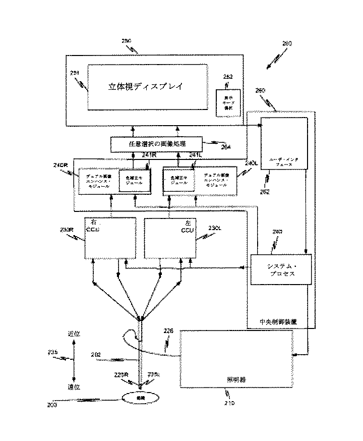
表2は、生物系で使用される一般的な蛍光蛋白質の例を示す表である。 Table 2 is a table showing examples of general fluorescent proteins used in biological systems.
当業者なら、蛍光物質が、患者の特定の組織と結び付く作用物質と結合することができることは分かる。特定の蛍光物質を選択したとき、照明器710D内の3つの可視色成分レーザ・モジュールのうちの1つが必要な励起波長を供給しない場合には、別のレーザ・モジュール710E4を照明器710Dに追加して、その蛍光物質の励起極大波長を有する光を供給する照明器710Eを得ることができる。したがって、関心のある1つまたは複数の蛍光物質および使用する異なる蛍光物質の数が与えられれば、適当な光源を照明器710Dに含めて、そのシーンのカラー画像の照明を行い、蛍光を励起することができる。
One skilled in the art will appreciate that a fluorescent material can bind to an agent that is associated with a particular tissue of a patient. If a specific phosphor is selected, another laser module 710E4 is added to the
上記の表1および2の例は、単なる例示であり、記載した具体的な例にこの態様を限定することを意図したものではない。本開示に鑑みて、組織の代替の撮像特性を選択して、利用する蛍光に基づいて適当な光源を選択することができる。 The examples in Tables 1 and 2 above are merely illustrative and are not intended to limit this aspect to the specific examples described. In view of the present disclosure, an alternative imaging characteristic of tissue can be selected and an appropriate light source can be selected based on the fluorescence used.
この態様では、プリズム・アセンブリ730R(730L)のコーティングされた第1の面731R(731L)、すなわちビーム・スプリッタは、複数のノッチ・フィルタを含むフィルタ790H(図7H)を有する。第1のノッチ・フィルタ791Hは、受光した光の赤色成分R1を反射し、受光した光の赤色成分Rの他の波長を透過させる。第2のノッチ・フィルタ792Hは、受光した光の緑色成分G1を反射し、受光した光の緑色成分Gの他の波長を透過させる。第3のノッチ・フィルタ793Hは、受光した光の青色成分B1を反射し、受光した光の青色成分Bの他の波長を透過させる。3つのノッチ・フィルタを使用するというのは、説明を容易にするためのものであり、3つの別個のフィルタに限定することを意図しているわけではない。3つの別個のノッチ・フィルタは、本明細書に記載する反射特性および透過特性を有する1つのマルチ・ノッチ・フィルタとみなすこともできる。 In this aspect, the coated first surface 731R (731L) of the prism assembly 730R (730L), ie, the beam splitter, has a filter 790H (FIG. 7H) that includes a plurality of notch filters. The first notch filter 791H reflects the red component R1 of the received light and transmits other wavelengths of the red component R of the received light. The second notch filter 792H reflects the green component G1 of the received light and transmits other wavelengths of the green component G of the received light. The third notch filter 793H reflects the blue component B1 of the received light and transmits other wavelengths of the blue component B of the received light. The use of three notch filters is for ease of explanation and is not intended to be limited to three separate filters. The three separate notch filters can also be considered as one multi-notch filter having the reflection and transmission characteristics described herein.
したがって、コーティングされた第1の面731R(731L)は、受光した光の赤色成分R1、受光した光の緑色成分G1、および受光した光の青色成分B1を、第2の面732R(732L)に反射する。第2の面732R(732L)は、コーティング面731R(731L)から受光した全ての波長を、画像取込みセンサ710R(710L)に反射する。 Therefore, the coated first surface 731R (731L) converts the red component R1 of the received light, the green component G1 of the received light, and the blue component B1 of the received light into the second surface 732R (732L). reflect. The second surface 732R (732L) reflects all wavelengths received from the coating surface 731R (731L) to the image capture sensor 710R (710L).
コーティングされた第1の面731R(731L)は、受光した光の赤色成分R1以外の赤色光、受光した光の緑色成分G1以外の緑色光、および受光した光の青色成分B1以外の青色光を、反射ユニット540R(540L)内の第3の面541R(541L)まで透過させる。第3の面541R(541L)は、コーティング面731R(731L)から受光した全ての波長を、画像取込みセンサ715R(715L)に反射する。 The coated first surface 731R (731L) receives red light other than the red component R1 of the received light, green light other than the green component G1 of the received light, and blue light other than the blue component B1 of the received light. Then, the light is transmitted to the third surface 541R (541L) in the reflection unit 540R (540L). The third surface 541R (541L) reflects all wavelengths received from the coating surface 731R (731L) to the image capture sensor 715R (715L).
このように、画像取込みセンサ710R(710L)は、レーザ照明されたシーンのRGB画像を取得する。これはカラー画像である。残りの全ての光は、画像取込みセンサ715R(715L)上に反射される。この光は、照明以外の光源からの光であるはずである。例えば、組織による自然蛍光がある場合、その蛍光は、画像取込みセンサ715R(715L)によって取り込まれる。画像取込みセンサ715R(715L)がカラー画像取込みセンサである場合には、蛍光は、任意の色を持つことができ、画像取込みセンサ715R(715L)にカラーで撮像される。コーティングされた第1の面731R(731L)のノッチ・フィルタにより、若干の蛍光の損失があることもある。この態様では、画像取込みセンサ710R(710L)は、カラー・フィルタ・アレイを有するカラー・センサである。カラー・フィルタ・アレイは、RGGBのベイヤー・カラー・フィルタ・アレイである。 Thus, the image capture sensor 710R (710L) obtains an RGB image of the laser illuminated scene. This is a color image. All remaining light is reflected onto the image capture sensor 715R (715L). This light should be from a light source other than illumination. For example, when there is natural fluorescence due to tissue, the fluorescence is captured by the image capture sensor 715R (715L). If the image capture sensor 715R (715L) is a color image capture sensor, the fluorescence can have any color and is imaged in color by the image capture sensor 715R (715L). There may be some fluorescence loss due to the notch filter of the coated first surface 731R (731L). In this aspect, image capture sensor 710R (710L) is a color sensor having a color filter array. The color filter array is an RGGB Bayer color filter array.
画像取込みセンサ715R(715L)として選択される画像取込みセンサの種類は、画像取込みセンサ715R(715L)が取り込むその他の光の特性によって決まる。画像取込みセンサ715R(715L)の利得およびその他のパラメータは、画像取込みセンサ715R(715L)が可能な限り最良の画像を取得するように、画像取込みセンサ710R(710L)とは無関係にすることができる。 The type of image capture sensor selected as the image capture sensor 715R (715L) depends on the characteristics of the other light captured by the image capture sensor 715R (715L). The gain and other parameters of the image capture sensor 715R (715L) can be independent of the image capture sensor 710R (710L) so that the image capture sensor 715R (715L) acquires the best possible image. .
1つの蛍光スペクトルが関心の対象である場合、または異なる蛍光スペクトルの識別には関心がない場合には、画像取込みセンサ715R(715L)は、モノクロ・センサでもよい。あるいは、例えば赤波長の蛍光スペクトルおよび緑波長の蛍光スペクトルなど、複数色の蛍光スペクトルが関心の対象である場合には、画像取込みセンサ715R(715L)は、ベイヤー・カラー・フィルタ・アレイを有するカラー画像取込みセンサとすればよい。 Image capture sensor 715R (715L) may be a monochrome sensor if one fluorescence spectrum is of interest or if there is no interest in identifying different fluorescence spectra. Alternatively, if multiple color fluorescence spectra are of interest, such as red wavelength fluorescence spectrum and green wavelength fluorescence spectrum, the image capture sensor 715R (715L) is a color with a Bayer color filter array. An image capturing sensor may be used.
モノクロ画像取込みセンサでは、解像度および集光の点で利点がある。カラー画像取込みセンサは、受光した光の1つまたは複数の波長について与える情報が多い。 Monochrome image capture sensors have advantages in terms of resolution and light collection. A color image capture sensor has a lot of information to give about one or more wavelengths of received light.
画像取込みセンサ715R(715L)の実施態様に関わらず、2つの画像取込みセンサが、同じシーンで同じ光学素子を透かし見ている。上述のように、同一平面の画像取込みセンサ710R(710L)および715R(715L)は、共通の前端部光学構造を有し、各センサまでの光路長がほぼ同じである。 Regardless of the implementation of image capture sensor 715R (715L), the two image capture sensors are seeing the same optical element in the same scene. As described above, coplanar image capture sensors 710R (710L) and 715R (715L) have a common front end optical structure and have substantially the same optical path length to each sensor.
レーザ照明の反射光ではない光で、画像取込みセンサ710R(710L)まで進む光が少量あったとしても、それは、レーザ照明の反射光より少ない。画像取込みセンサ710R(710L)および715R(715L)によって取り込まれる画像のスペクトル応答が広く、位置合わせが良好であると仮定すれば、デュアル画像エンハンス・モジュール240R(240L)は、画像取込みセンサ715R(715L)が取り込んだ画像を用いて、画像取込みセンサ710R(710L)が取り込んだ画像を補正することができる。 Even if there is a small amount of light that is not reflected from the laser illumination and travels to the image capture sensor 710R (710L), it is less than the reflected light from the laser illumination. Assuming that the images captured by the image capture sensors 710R (710L) and 715R (715L) have a wide spectral response and good alignment, the dual image enhancement module 240R (240L) can be used by the image capture sensors 715R (715L). ) Can be used to correct the image captured by the image capture sensor 710R (710L).
波長R1、G1およびB1を有する光を生成するような照明器710D内の照明モジュール以外の照明モジュールからの励起波長によって蛍光が励起される場合には、例えば遮蔽体570R(570L)とセンサ・アセンブリ720R(720L)との間の画像取込みユニットの撮像経路内に、励起阻止ノッチ・フィルタが必要である。蛍光の励起波長に関わりなく、蛍光は、可視スペクトル内とすることができ、画像取込みセンサ715R(715L)上で撮像することができる。必要に応じて、複数の蛍光を同時に撮像することもでき、発光スペクトルが、画像取込みセンサ715R(715L)上で異なる色を励起する。
When fluorescence is excited by an excitation wavelength from an illumination module other than the illumination module in
デュアル画像エンハンス・モジュール240R(240L)の構成は、第2の画像取込みセンサ715R(715L)がカラー画像取込みセンサであるかモノクロ画像取込みセンサであるかによって決まる。両画像取込みセンサがカラー・センサである場合には、上述のように、CCU230R(230L)が2つの取り込まれた画像をモザイク解除処理し、制御装置260が出力画像の各画素ごとにN要素色成分ベクトルを生成する。N要素色成分ベクトルの色成分のうち3つは、カラー画像を表し、残りの色成分は、蛍光を表す。第2の画像取込みセンサがモノクロである場合には、第2の取り込まれた画像のモザイク解除処理は不要である。 The configuration of the dual image enhancement module 240R (240L) depends on whether the second image capture sensor 715R (715L) is a color image capture sensor or a monochrome image capture sensor. When both image capture sensors are color sensors, as described above, the CCU 230R (230L) performs mosaic removal processing on the two captured images, and the control device 260 performs N element color for each pixel of the output image. Generate component vectors. Three of the color components of the N element color component vector represent a color image, and the remaining color components represent fluorescence. When the second image capture sensor is monochrome, the mosaic removal process for the second captured image is not necessary.
このように、第2の画像取込みセンサ715R(715L)の実施態様に関わらず、制御装置260は、出力画像の画素について、少なくとも4要素色成分ベクトルを、第1の画像中のそれに対応する画素の色成分ベクトルおよび第2の画像中のそれに対応する画素の色成分ベクトルから生成するように構成する。4要素色成分ベクトルの要素のうち3つは、可視カラー画像のものであり、4要素色成分ベクトルの第4の要素は、蛍光画像のものである。 Thus, regardless of the implementation of the second image capture sensor 715R (715L), the controller 260 may provide at least a four-element color component vector for pixels of the output image and corresponding pixels in the first image. And the color component vector of the corresponding pixel in the second image. Three of the elements of the four-element color component vector are from the visible color image, and the fourth element of the four-element color component vector is from the fluorescent image.
図7Aの態様および図7Aに関連して上述した各例では、立体視チャネルの画像取込みセンサは、同一平面にある。これは単なる例示であり、限定を目的としたものではない。例えば、これらの画像取込みセンサのうちの第1の画像取込みセンサが、第1の平面内にセンサ上面を有し、これらの画像取込みセンサのうちの第2の画像取込みセンサが、第2の平面内にセンサ上面を有してもよい。第1の平面と第2の平面は互いに平行であり、既知の距離だけ離間している(図9参照)。ビーム・スプリッタと反射ユニット内の反射面との間の間隔を調節して、第1の画像取込みセンサまでの第1の光路長が第2の画像取込みセンサまでの第2の光路長とほぼ等しくなるように、上記の既知の距離を補償する。したがって、2つの光路長はほぼ等しいままであるので、上述の図7Aの各態様は、そのままこの構成に適用可能である。 In the embodiment of FIG. 7A and each example described above in connection with FIG. 7A, the stereoscopic channel image capture sensors are in the same plane. This is merely an example and is not intended to be limiting. For example, a first image capture sensor of these image capture sensors has a sensor top surface in a first plane, and a second image capture sensor of these image capture sensors is a second plane. You may have a sensor upper surface in it. The first plane and the second plane are parallel to each other and are separated by a known distance (see FIG. 9). Adjusting the spacing between the beam splitter and the reflecting surface in the reflecting unit, the first optical path length to the first image capture sensor is approximately equal to the second optical path length to the second image capture sensor. The known distance is compensated so that Accordingly, since the two optical path lengths remain substantially equal, the above-described aspects of FIG. 7A can be directly applied to this configuration.
被写界深度の拡大
外科手術内視鏡では、可能な限り鮮鋭で明るい画像を執刀医に提供することが望ましい。そのためには、可能な限り大きな開口を有するレンズ設計が必要である。開口が大きくなるほど、形成される画像が(センサの限界内で)鮮鋭になり、通過する光が増えるので画像が明るくなる(信号対雑音比が向上する)。ただし、開口が大きくなると被写界深度が浅くなるという交換条件がある。執刀医は、カメラから様々な距離のところにある複数のものを見るときに撮像システムの焦点を制御しなければならなくなることを避けるために、大きな被写界深度を有する画像を好む。したがって、執刀医にとっては、大きな開口の鮮鋭度および輝度と、大きく改善された被写界深度とを有する画像があれば好ましい。この目的を達成するために、画像取込みユニット825Lおよび825R(図8A)はそれぞれ、異なる焦点で組織803の画像を取り込む。デュアル画像エンハンス・モジュール240R、240L(図2)は、取り込まれた画像を処理し、以前には実現できなかった被写界深度機能を執刀医に提供する。
Enhancing depth of field In a surgical endoscope, it is desirable to provide the surgeon with the sharpest and brightest image possible. This requires a lens design with as large an aperture as possible. The larger the aperture, the sharper the image formed (within the limits of the sensor) and the brighter the image because more light passes through (improves the signal-to-noise ratio). However, there is an exchange condition that the depth of field becomes shallower as the aperture becomes larger. The surgeon prefers images with a large depth of field to avoid having to control the focus of the imaging system when viewing multiple things at various distances from the camera. Therefore, it is desirable for the surgeon to have an image with a large aperture sharpness and brightness and a greatly improved depth of field. To achieve this goal, image capture units 825L and 825R (FIG. 8A) each capture images of tissue 803 at different focal points. Dual image enhancement modules 240R, 240L (FIG. 2) process the captured images and provide the surgeon with a depth of field function that was not previously possible.
例えば、1つの態様では、センサ・アセンブリ820R(820L)によって取り込まれた第1の画像881(図8B)は、第1の焦点を有する。センサ・アセンブリ820R(820L)によって取り込まれた第2の画像882(図8C)は、第2の焦点を有する。画像881では、画像の中央のフィーチャは、濃いはっきりした線で表すように焦点が合っている。画像881の左側および右側のフィーチャは、画像取込みユニット825R(825L)からさらに離れており、網掛けで表すように焦点が合っていない。画像882では、画像の中央のフィーチャは、網掛けで表すように焦点が合っていない。画像882の左側および右側のフィーチャは、濃いはっきりした線で表すように焦点が合っていない。
For example, in one aspect, the first image 881 (FIG. 8B) captured by the sensor assembly 820R (820L) has a first focus. A second image 882 (FIG. 8C) captured by sensor assembly 820R (820L) has a second focus. In
以下でさらに完全に説明するように、画像881および882の焦点が合っている部分を使用して、立体視ディスプレイ251(図8D)に送信する焦点の合った複合画像を生成する。これにより、画像881および882のいずれかで得られるより良好な被写界深度を有する画像が得られる。この手法のもう1つの利点は、画像881および882からの情報ならびに鮮鋭度メトリックを使用して、複数の仮想カメラの視点からの画像を生成し、これが立体視ディスプレイ251に送信されて表示される。これにより、執刀医は、内視鏡802を物理的に動かすことなく、わずかに異なる視点から組織803を見ることができる。
As described more fully below, the in-focus portions of
図8Aは、画像取込みユニット825Lおよび825Rならびに照明器からの光を供給する照明チャネル805を備える立体視内視鏡802の遠位端部を示す概略図である。矢印835が示すように、遠位方向は、組織803に向かう方向であり、近位方向は、組織803から離れる方向である。 FIG. 8A is a schematic diagram showing the distal end of a stereoscopic endoscope 802 with image capture units 825L and 825R and an illumination channel 805 that supplies light from the illuminator. As arrow 835 indicates, the distal direction is the direction toward tissue 803 and the proximal direction is the direction away from tissue 803.
各画像取込みユニット825R、825Lは、レンズ・アセンブリ801R、801L、およびセンサ・アセンブリ820R、820Lを含む。センサ・アセンブリ820R、820Lは、レンズ・アセンブリ801R、801Lを通過した光を受光するように位置決めされる。各センサ・アセンブリ820R、820Lは、1つの態様では、プリズム・アセンブリ830R、830L、反射ユニット840R、840L、および同一平面画像取込みセンサ(810R、815R)、(810L、815L)を含む。ただし、図8Aの構成を用いて説明する態様で、図9に示す構成を使用してもよい。立体視内視鏡802は、内視鏡802と呼ばれることもある。 Each image capture unit 825R, 825L includes a lens assembly 801R, 801L and a sensor assembly 820R, 820L. The sensor assemblies 820R, 820L are positioned to receive light that has passed through the lens assemblies 801R, 801L. Each sensor assembly 820R, 820L, in one aspect, includes a prism assembly 830R, 830L, a reflection unit 840R, 840L, and a coplanar image capture sensor (810R, 815R), (810L, 815L). However, the configuration illustrated in FIG. 9 may be used in a mode described using the configuration in FIG. 8A. The stereoscopic endoscope 802 may be referred to as an endoscope 802.
以下の記述では、立体視内視鏡802の右チャネルの光路について述べる。内視鏡802の対称性により、立体視内視鏡802の左チャネルの光路は、右チャネルの光路と同じであるので、以下の記述では、左チャネルの参照番号を、右チャネルの要素の説明の後の括弧内に記載する。これは、その記述が左チャネルの対応する要素にも当てはまることを示している。また、説明する撮像処理は、連続的なビデオ・シーケンスがディスプレイに送られるように実時間で実行される。 In the following description, the optical path of the right channel of the stereoscopic endoscope 802 will be described. Because of the symmetry of the endoscope 802, the left channel optical path of the stereoscopic endoscope 802 is the same as the right channel optical path, so in the following description, the left channel reference number is referred to as the right channel element description. In parentheses after. This indicates that the description also applies to the corresponding element of the left channel. Also, the imaging process described is performed in real time so that a continuous video sequence is sent to the display.
組織803からの光は、レンズ・アセンブリ801R(801L)内のレンズ素子804R(804L)および遮蔽体870R(870L)を通過する。レンズ・アセンブリ401B(図4B)内の要素は、レンズ素子804R(804L)の例である。レンズ・アセンブリ801R(801L)を通過する光は、画像取込みユニット825L(825R)によって受光され、プリズム・アセンブリ830Rに進入する。プリズム・アセンブリ830R(830L)は、受光した光の第1の割合を反射するビーム・スプリッタ831R(831L)を含む。ビーム・スプリッタ831R(831L)は、受光した光の第2の割合をこのビームスプリッタ831R(831L)を通じて反射ユニット840R(840L)まで通過させる。
Light from tissue 803 passes through lens element 804R (804L) and shield 870R (870L) in lens assembly 801R (801L). The elements in
1つの態様では、ビーム・スプリッタ831R(831L)は、コーティングされた第1の面831R(831L)として実装される。コーティングされた第1の面831R(831L)によって反射された光は、第2の面832R(832L)によって受光され、第2の面832R(832L)は、この光を、例えば反射するなどして、第1の画像取込みセンサ810R(810L)に向けて送る。表面832R(832L)は、コーティング面または内部全反射面のいずれかとすることができる。コーティングされた第1の面831R(831L)を透過した光は、反射ユニット540R(540L)の第3の面541R(541L)によって受光され、第3の面541R(541L)は、この光を、例えば反射するなどして、第2の画像取込みセンサ815R(815L)に向けて送る。 In one aspect, the beam splitter 831R (831L) is implemented as a coated first surface 831R (831L). The light reflected by the coated first surface 831R (831L) is received by the second surface 832R (832L), and the second surface 832R (832L) reflects this light, for example. To the first image capturing sensor 810R (810L). The surface 832R (832L) can be either a coating surface or an internal total reflection surface. The light transmitted through the coated first surface 831R (831L) is received by the third surface 541R (541L) of the reflection unit 540R (540L), and the third surface 541R (541L) For example, it is reflected and sent to the second image capture sensor 815R (815L).
第2の面832R(832L)は、コーティングされた第1の面831R(831L)によって反射された光以外の光が第2の面832R(832L)に入射しないように位置決めされる。1つの態様では、コーティング面831R(831L)に対する光の入射角は、45度未満である。 The second surface 832R (832L) is positioned so that light other than the light reflected by the coated first surface 831R (831L) does not enter the second surface 832R (832L). In one aspect, the incident angle of light with respect to the coating surface 831R (831L) is less than 45 degrees.
1つの態様では、プリズム・アセンブリ830R(830L)および反射ユニット840R(840L)は、プリズム・アセンブリ830R(830L)を含むペンタプリズムを有するプリズム構造に含まれる。この態様のプリズム構造は、受光した光を第1の割合と第2の割合とに分割する埋込みコーティング面431Bを有するプリズム構造460(図4B)と等価である。したがって、プリズム構造460の説明が、この態様で使用されるプリズム構造にも当てはまる。
In one aspect, prism assembly 830R (830L) and reflection unit 840R (840L) are included in a prism structure having a pentaprism that includes prism assembly 830R (830L). The prism structure of this embodiment is equivalent to a prism structure 460 (FIG. 4B) having an embedded
1つの態様では、第1の割合と第2の割合はほぼ等しい。別の態様では、第1の割合と第2の割合は異なる。したがって、プリズム・アセンブリ830R(830L)は、受光した光を2つの部分、すなわち(i)第1の部分と呼ばれることもある受光した光の第1の割合と、(ii)第2の部分と呼ばれることもある受光した光の第2の割合とに分離するビーム・スプリッタ831R(831L)を含む。 In one aspect, the first ratio and the second ratio are approximately equal. In another aspect, the first ratio and the second ratio are different. Accordingly, prism assembly 830R (830L) receives received light in two parts: (i) a first proportion of received light, sometimes referred to as a first part, and (ii) a second part; It includes a beam splitter 831R (831L) that separates into a second proportion of received light, sometimes called.
画像取込みセンサ810R(810L)および815R(815L)は、同一平面にある。1つの態様では、遮蔽体870R(870L)からコーティングされた第1の面831R(831L)および第2の面832R(832L)を経由して画像取込みセンサ810R(810L)に至る第1の光路長は、第1の長さである。遮蔽体870R(870L)からコーティングされた第1の面831R(831L)およびアセンブリ840R(840L)内の第3の面841R(841L)を経由して画像取込みセンサ815R(815L)に至る第2の光路長は、第2の長さである。第1の長さと第2の長さは異なる、すなわちほぼ等しいとは言えない。この場合も、遮蔽体870R(870L)から開始する光路長の定義は例示であり、限定を目的としたものではない。これらの等しくない光路長は、受光した光がプリズム・アセンブリ830R(830L)に進入するプリズム・アセンブリ830R(830L)の遠位面を基準にする、レンズ・アセンブリ801R(801L)内の最初の要素を基準にする、またはコーティングされた第1の面831R(831L)を基準にするなど、様々に定義することができる。別の態様では、これらの異なる光路長は、2つの画像センサ領域に設けた屈折率の異なるガラス板またはその他の同様の手段を用いて実現することができる。 Image capture sensors 810R (810L) and 815R (815L) are in the same plane. In one embodiment, the first optical path length from the shield 870R (870L) to the image capture sensor 810R (810L) via the coated first surface 831R (831L) and the second surface 832R (832L). Is the first length. A second surface from the shield 870R (870L) to the image capture sensor 815R (815L) via the coated first surface 831R (831L) and the third surface 841R (841L) in the assembly 840R (840L). The optical path length is the second length. The first length and the second length are different, i.e., not substantially equal. Also in this case, the definition of the optical path length starting from the shield 870R (870L) is an example, and is not intended to be limited. These unequal optical path lengths are the first element in lens assembly 801R (801L) relative to the distal surface of prism assembly 830R (830L) where the received light enters prism assembly 830R (830L). , Or the coated first surface 831R (831L) as a reference. In another aspect, these different optical path lengths can be achieved using glass plates of different refractive index provided in the two image sensor regions or other similar means.
このように、同一平面の画像取込みセンサ810R(810L)および815R(815L)は、レンズ・アセンブリ801R(801L)内の前端部光学構造を通る光路長は共通であるが、センサ・アセンブリ820R(820L)内の各画像取込みセンサまでの光路長は異なる。第1の画像取込みセンサ810R(810L)は、センサ・アセンブリ820R(820L)が受光した光の第1の部分から画像を取り込む。第2の画像取込みセンサ815R(815L)は、センサ・アセンブリ820R(820L)が受光した光の第2の部分から画像を取り込む。 Thus, coplanar image capture sensors 810R (810L) and 815R (815L) share a common optical path length through the front end optical structure in lens assembly 801R (801L), but sensor assembly 820R (820L). The optical path length to each image capturing sensor in () is different. The first image capture sensor 810R (810L) captures an image from a first portion of light received by the sensor assembly 820R (820L). The second image capture sensor 815R (815L) captures an image from the second portion of light received by the sensor assembly 820R (820L).
1つの態様では、画像取込みセンサ810R(810L)および815R(815L)はそれぞれ、カラー・フィルタ・アレイを有するカラー・センサである。別の態様では、これらのカラー・センサの1つからカラー・フィルタ・アレイが取り外され、そのセンサはモノクロ・センサとして機能する。モノクロ・センサを使用するときには、2つの画像の焦点が違いすぎない場合、例えば2つの画像が、それら2つの画像の鮮鋭度曲線885と886が交差する点の近傍で合焦している場合(図8E参照)には、モノクロ・センサが取り込んだ画像の鮮鋭度が、カラー画像に伝達される。 In one aspect, image capture sensors 810R (810L) and 815R (815L) are each color sensors having a color filter array. In another aspect, the color filter array is removed from one of these color sensors, and the sensor functions as a monochrome sensor. When using a monochrome sensor, if the two images are not too focused, for example, the two images are in focus near the point where the sharpness curves 885 and 886 of the two images intersect ( In FIG. 8E), the sharpness of the image captured by the monochrome sensor is transmitted to the color image.
1つの態様では、プリズム・アセンブリ830R(830L)のコーティングされた第1の面831R(831L)は、プリズム・アセンブリ830R(830L)が受光した光の反射させる部分と透過させる部分とがほぼ等しくなるように、すなわち第1の割合と第2の割合とがほぼ等しくなるように構成される。したがって、この態様のビーム・スプリッタ831R(831L)は、上述のバランス・ビーム・スプリッタである。この例では、画像取込みセンサ810R(810L)および815R(815L)はそれぞれ、カラー・フィルタ・アレイを有するカラー・センサである。このカラー・フィルタ・アレイは、ベイヤー・カラー・フィルタ・アレイである。したがって、2つのベイヤー・パターン画像取込みセンサ810R(810L)および815R(815L)が、同じシーンで同じ光学素子を透かし見ている。ここで、ベイヤー・パターン画像取込みセンサは、ベイヤー・カラー・フィルタ・アレイを含む単一のチップ・センサ、または単一のチップの一部にある。上述のように、同一平面の画像取込みセンサ810R(810L)および815R(815L)は、共通の前端部光学構造を有しているが、各センサまでの光路長は異なる。 In one aspect, the coated first surface 831R (831L) of the prism assembly 830R (830L) has approximately equal portions for reflecting and transmitting light received by the prism assembly 830R (830L). That is, the first ratio and the second ratio are configured to be substantially equal. Therefore, the beam splitter 831R (831L) of this aspect is the above-described balance beam splitter. In this example, image capture sensors 810R (810L) and 815R (815L) are each color sensors having a color filter array. This color filter array is a Bayer color filter array. Thus, the two Bayer pattern image capture sensors 810R (810L) and 815R (815L) are seeing the same optical element in the same scene. Here, the Bayer pattern image capture sensor is on a single chip sensor including a Bayer color filter array, or part of a single chip. As described above, the same plane image capture sensors 810R (810L) and 815R (815L) have a common front end optical structure, but the optical path lengths to the sensors are different.
画像取込みセンサ810R(810L)まで進む光は、画像取込みユニット825R(825L)から第1の物体距離DAのところに合焦する第1の画像として取り込まれる。例えば、図8Bを参照されたい。画像取込みセンサ815R(815L)まで進む光は、センサ815R(815L)に到達するまでにこれよりわずかに長い経路をたどり、画像取込みユニットから第2の物体距離DBのところに合焦する第2の画像として取り込まれる。例えば、図8Cを参照されたい。距離DBは、距離DAより長い。この経路長の差は、例えばレンズ素子804R(804L)の焦点距離、2つの取り込まれた画像それぞれの最良の合焦が得られる距離など、前端部の光学的設計に基づく。 The light traveling to the image capture sensor 810R (810L) is captured as a first image focused from the image capture unit 825R (825L) to the first object distance DA. For example, see FIG. 8B. The light traveling to the image capture sensor 815R (815L) follows a slightly longer path before reaching the sensor 815R (815L) and is focused from the image capture unit to the second object distance DB. Captured as an image. For example, see FIG. 8C. The distance DB is longer than the distance DA. This difference in path length is based on the optical design of the front end, such as the focal length of the lens element 804R (804L), the distance that provides the best focus for each of the two captured images.
第1の画像と第2の画像は位置合わせされ、同じレンズ素子804R(804L)を通して撮像される。2つの画像の焦点面は異なる。2つの画像の被写界深度も異なる。例えば画像881など、距離DAのところに合焦する画像は、短い被写界深度を有するが、例えば画像882など、距離DBのところに合焦する画像は、それより広い被写界深度を有する。
The first image and the second image are aligned and imaged through the same lens element 804R (804L). The focal planes of the two images are different. The depth of field of the two images is also different. For example, an image that focuses on the distance DA, such as the
上述のように、執刀医は、ユーザ・インタフェース262を使用して、デュアル画像エンハンス・モジュール240R(240L)に、2つの取り込まれた画像(図8Bおよび図8C)から被写界深度がエンハンスされた焦点の合った画像(図8D)を生成させることができる。あるいは、執刀医は、立体視ディスプレイ251と呼ばれることもある執刀医用制御コンソールのディスプレイ251における調整が外科手術部位における外科手術に関する調整と一致するように、ディスプレイの2つの面に2つの画像を表示することができる。最後に、執刀医は、第1の焦点を有する第1の画像と第2の焦点を有する第2の画像とを切り替えることができる。
As described above, the surgeon uses the
1つの態様では、デュアル画像エンハンス・モジュール240R(240L)は、画像取込みセンサ810R(810L)および815R(815L)によって取り込まれた2つの画像から、被写界深度が拡大された焦点の合った画像を生成する。第1の態様では、第1の画像中のある画素群すなわちタイルについて、第1の鮮鋭度メトリックを生成し、第2の画像中のそれに対応する画素群について、第2の鮮鋭度メトリックを生成する。この2つの鮮鋭度メトリックを比較して、どちらの鮮鋭度メトリックの方が大きいかを判定する。最大の鮮鋭度メトリックを有する画素群(あるいはそのタイル内で選択された1つまたは複数の画素)を、混合画像用に選択する。デュアル画像エンハンス・モジュール240R(240L)は、2つの取り込まれた画像を画素群ごとに調べ、2つの画素群のうちの一方を、2つの取り込まれた画像より大きな視野にわたって焦点が合っている混合画像に含めるものとして選択する。 In one aspect, dual image enhancement module 240R (240L) is a focused image with increased depth of field from two images captured by image capture sensors 810R (810L) and 815R (815L). Is generated. In a first aspect, a first sharpness metric is generated for a group of pixels or tiles in a first image, and a second sharpness metric is generated for a corresponding group of pixels in a second image. To do. The two sharpness metrics are compared to determine which sharpness metric is greater. The group of pixels having the maximum sharpness metric (or one or more selected pixels in the tile) is selected for the mixed image. The dual image enhancement module 240R (240L) examines the two captured images for each group of pixels and mixes one of the two groups of pixels in focus over a larger field of view than the two captured images. Select to include in the image.
図8Eは、画像取込みセンサ810R(810L)が取り込んだ画像の鮮鋭度プロファイル885、および画像取込みセンサ815R(815L)が取り込んだ画像の鮮鋭度プロファイル886を示すグラフである。鮮鋭度プロファイルは、内視鏡の遠位端部からの距離に対する画像取込みセンサが取り込んだ画像の鮮鋭度を示す曲線である。1つの態様では、鮮鋭度プロファイル885および886は、内視鏡802を用いて実行した較正と、内視鏡802の遠位端部から異なる距離のところにある複数の既知の物体を撮影した複数の画像とに基づいて、経験的に生成される。 FIG. 8E is a graph showing the sharpness profile 885 of the image captured by the image capture sensor 810R (810L) and the sharpness profile 886 of the image captured by the image capture sensor 815R (815L). The sharpness profile is a curve showing the sharpness of the image captured by the image capture sensor relative to the distance from the distal end of the endoscope. In one aspect, the sharpness profiles 885 and 886 are a calibration performed using the endoscope 802 and a plurality of images of a plurality of known objects at different distances from the distal end of the endoscope 802. And empirically generated based on the image.
1つの態様では、プロファイル885および886は、参照テーブルとしてメモリに記憶される。記憶された鮮鋭度プロファイルを、デュアル画像エンハンス・モジュール240R(240L)が使用して、画像取込みユニット825R(825L)内の光学素子を動かすことなく内視鏡802を動かすときに、画像取込みセンサ810R(810L)が取り込んだ第1の画像を表示するか、画像取込みセンサ815R(815L)が取り込んだ第2の画像を表示するかを決定する。デュアル画像エンハンス・モジュール240R(240L)は、第1および第2の画像それぞれについて、当業者には既知の従来技術を用いて鮮鋭度メトリックを生成する。デュアル画像エンハンス・モジュール240R(240L)は、鮮鋭度プロファイル885および886と鮮鋭度メトリックとを使用して、内視鏡802の遠位端部と各画像の組織との間の距離を決定する。 In one aspect, profiles 885 and 886 are stored in memory as a lookup table. When the stored sharpness profile is used by the dual image enhancement module 240R (240L) to move the endoscope 802 without moving the optical elements in the image capture unit 825R (825L), the image capture sensor 810R. Whether to display the first image captured by (810L) or the second image captured by the image capture sensor 815R (815L) is determined. Dual image enhancement module 240R (240L) generates a sharpness metric for each of the first and second images using conventional techniques known to those skilled in the art. Dual image enhancement module 240R (240L) uses sharpness profiles 885 and 886 and a sharpness metric to determine the distance between the distal end of endoscope 802 and the tissue of each image.
例えば、第1の画像の鮮鋭度メトリックが0.5である場合には、組織803までの距離DAは、鮮鋭度プロファイル885に基づき、約42ミリメートル(mm)または約27ミリメートル(mm)のいずれかとなる。第2の画像の鮮鋭度メトリックが0.43である場合には、組織803までの距離DBは、鮮鋭度プロファイル886に基づき、約42ミリメートル(mm)である。あるいは、第2の画像の鮮鋭度メトリックが約0.08である場合には、組織までの距離は、約27ミリメートル(mm)である。なお、鮮鋭度プロファイル885は、鮮鋭度メトリックに基づくので組織の深さについては曖昧であるが、組織の深さは、第2の曲線886によって曖昧さが除去されることに留意されたい。両画像はほぼ同時に得られたものであるので、この曖昧さ除去は、時間的な影響によって歪むことはない。デュアル画像エンハンス・モジュール240R(240L)は、この2つの画像の間の相対鮮鋭度メトリックと、これらの曲線のアプリオリ(a-priori)な構成とを使用して、内視鏡802が移動して、画像取込みユニットから組織までの距離が変化するときに、2つの画像のうちのどちらを表示するかを決定する。中央制御装置260は、内視鏡の遠位端部の位置を知っている。 For example, if the sharpness metric of the first image is 0.5, the distance DA to the tissue 803 is either about 42 millimeters (mm) or about 27 millimeters (mm) based on the sharpness profile 885. It becomes. If the sharpness metric of the second image is 0.43, the distance DB to the tissue 803 is about 42 millimeters (mm) based on the sharpness profile 886. Alternatively, if the sharpness metric of the second image is about 0.08, the distance to the tissue is about 27 millimeters (mm). Note that although the sharpness profile 885 is based on a sharpness metric, the tissue depth is ambiguous, but the tissue depth is removed by the second curve 886. Since both images were obtained almost simultaneously, this disambiguation is not distorted by temporal effects. The dual image enhancement module 240R (240L) uses the relative sharpness metric between the two images and the a-priori configuration of these curves to move the endoscope 802. Determine which of the two images to display when the distance from the image capture unit to the tissue changes. The central controller 260 knows the position of the distal end of the endoscope.
内視鏡802を移動させて組織803に近づけた場合には、第1の取り込まれた画像が、デュアル画像エンハンス・モジュール240R(240L)によってディスプレイ251に送信される。内視鏡802を移動させて組織803から遠ざけた場合には、デュアル画像エンハンス・モジュール240R(240L)は、内視鏡802の遠位端部の組織803からの距離を、プロファイル交差距離と呼ばれる鮮鋭度プロファイル885および886が交差する距離とを比較する。内視鏡802の遠位端部の組織803からの距離がプロファイル交差距離より小さい場合には、第1の取り込まれた画像がディスプレイ251に伝送される。内視鏡802の遠位端部の組織803からの距離がプロファイル交差距離より大きい場合には、第2の取り込まれた画像がディスプレイ251に伝送される。したがって、前段落の鮮鋭度メトリックスでは、内視鏡802の遠位端部が組織803から45mm未満のところにあるときには、第1の画像が執刀医に提示されることになる。内視鏡802の遠位端部が組織803から45mmを超えるところにあるときには、第2の画像が執刀医に提示されることになる。したがって、内視鏡802を移動させたとき、画像取込みユニット825R(825L)内の光学素子を動かさなくても、適当な画像が執刀医に提示される。
When the endoscope 802 is moved closer to the tissue 803, the first captured image is transmitted to the
さらに、2つの画像のうちのどちらを執刀医に提示するかの判定は、相対鮮鋭度メトリックのみに基づいて行うことができる。つまり、組織の深さの計算は不要である。ステレオ・ビューアの左右の目に提示される画像対は、調和した状態に保たれ、鮮鋭度メトリックの比較では、第1の画像または第2の画像を使用する判定中に左目用に取り込まれた画像対からのデータおよび右目用に取り込まれた画像対からのデータを使用することができる。一般に、提示される画像全体の焦点を切り替える場合には、第1の画像が左右両目用に選択されるか、または第2の画像が左右の目用に選択される。 Furthermore, the determination of which of the two images to present to the surgeon can be made based solely on the relative sharpness metric. That is, it is not necessary to calculate the tissue depth. The image pairs presented in the left and right eyes of the stereo viewer were kept in harmony, and the sharpness metric comparison was captured for the left eye during the decision to use the first or second image Data from image pairs and data from image pairs captured for the right eye can be used. Generally, when switching the focus of the entire image to be presented, the first image is selected for both the left and right eyes, or the second image is selected for the left and right eyes.
別の態様では、取り込まれた2つの画像および鮮鋭度プロファイル885、886を使用して、深さマップを作成する。鮮鋭度プロファイル885を鮮鋭度プロファイル886に分割して、距離に対する鮮鋭度メトリックのチャネル鮮鋭度プロファイルを生成する。例えば、所与の距離のプロファイル886の値を、その所与の距離のプロファイル885の値で割って、その所与の距離の鮮鋭度メトリックを得る。この鮮鋭度メトリックを、スライディング・タイルを使用して計算して、画像全体の深さマップを作成することができる。当然、この情報を、さらに多くの従来のステレオ・マッチング・アルゴリズムと組み合わせて、さらに良い状態の深さマップを生成することができる。 In another aspect, the two captured images and sharpness profiles 885, 886 are used to create a depth map. The sharpness profile 885 is divided into sharpness profiles 886 to produce a sharpness metric channel sharpness profile over distance. For example, the value of a given distance profile 886 is divided by the value of the given distance profile 885 to obtain the sharpness metric for that given distance. This sharpness metric can be calculated using sliding tiles to create a depth map of the entire image. Of course, this information can be combined with more conventional stereo matching algorithms to produce a better state depth map.
1つの態様では、鮮鋭度プロファイル885および886は、内視鏡802を用いて実行した較正と、内視鏡802の遠位端部から異なる距離のところにある複数の既知の物体を撮影した複数の画像とに基づいて、経験的に生成される。鮮鋭度プロファイルは、画像取込みユニット825Rおよび画像取込みユニット825Lの両方について得る。チャネル鮮鋭度プロファイルは、左右のチャネルのそれぞれについて生成される。1つの態様では、左右のチャネル鮮鋭度プロファイルは、参照テーブルとしてメモリ899(図8F)に保存される。 In one aspect, the sharpness profiles 885 and 886 are a calibration performed using the endoscope 802 and a plurality of images of a plurality of known objects at different distances from the distal end of the endoscope 802. And empirically generated based on the image. Sharpness profiles are obtained for both image capture unit 825R and image capture unit 825L. A channel sharpness profile is generated for each of the left and right channels. In one aspect, the left and right channel sharpness profiles are stored in memory 899 (FIG. 8F) as a lookup table.
基本的には、第1の取り込まれた画像の画素と第2の取り込まれた画像の画素との間には1対1の対応があることに留意されたい。場合によっては、この1対1の対応を確立するのに、較正、および若干の画像変形またはソフトウェアによる画像間の位置合わせが必要になることがある。デュアル画像エンハンス・モジュール240R(240L)は、当業者には既知の従来技術を用いて、第1および第2の各画像中の対応する画素の周りのタイルまたは画素群の鮮鋭度メトリックを生成する。第1の取り込まれた画像中の画素、またはその画素の周りの画素群の鮮鋭度メトリックを、第2の取り込まれた画像中の対応する画素、またはその対応する画素の周りの対応する画素群の鮮鋭度メトリックに分割して、それらの画素のチャネル鮮鋭度プロファイルを生成する。それらの画素のチャネル鮮鋭度プロファイルを使用して、チャネル鮮鋭度プロファイル上のポイントの位置を突き止める。チャネル鮮鋭度プロファイル上のそのポイントに対応する距離が、その画素の(X、Y)位置と関連付けられる深さである。このプロセスを取り込まれた画像中の各画素について実行して、取り込まれた画像の深さマップを生成する。 It should be noted that there is basically a one-to-one correspondence between pixels of the first captured image and pixels of the second captured image. In some cases, establishing this one-to-one correspondence may require calibration and some image deformation or alignment between images by software. Dual image enhancement module 240R (240L) generates a sharpness metric of tiles or groups of pixels around corresponding pixels in each of the first and second images using conventional techniques known to those skilled in the art. . The sharpness metric of a pixel in the first captured image, or a group of pixels around the pixel, and a corresponding pixel in the second captured image, or a corresponding group of pixels around the corresponding pixel. To generate a channel sharpness profile for those pixels. The channel sharpness profile of those pixels is used to locate points on the channel sharpness profile. The distance corresponding to that point on the channel sharpness profile is the depth associated with the (X, Y) position of that pixel. This process is performed for each pixel in the captured image to generate a depth map of the captured image.
1つの態様では、この深さマップを使用して、内視鏡802の視点とは異なる視点、すなわち仮想カメラの視点からの組織803のシーンのビューを生成する。中央制御装置260は、2次元仮想化モジュール890(図8F)を使用して、その仮想カメラの視点の立体視画像対を生成する。 In one aspect, this depth map is used to generate a view of the scene of the tissue 803 from a viewpoint that is different from the viewpoint of the endoscope 802, ie, the viewpoint of the virtual camera. The central controller 260 uses the two-dimensional virtualization module 890 (FIG. 8F) to generate a stereoscopic image pair of the viewpoint of the virtual camera.
3次元仮想化モジュール890は、内視鏡802の右の立体視チャネルで取り込まれた第1および第2の画像を使用し、右チャネルから見たシーンの第1のチャネルの深さマップを生成する。同様に、3次元仮想化モジュール890は、内視鏡802の左の立体視チャネルで取り込まれた第1および第2の画像を使用し、左チャネルから見たシーンの第2のチャネルの深さマップを生成する。画像のステレオ・マッチングで得られる追加情報を使用して、結合深さマップの安定度および精度を向上させることもできる。シーンの3次元表面は、第1および第2のチャネルの深さマップを使用して生成され、4つの取り込まれた画像の最も良く焦点が合っている部分を3次元表面上に投影し、テクスチャ処理して、テクスチャ処理した3次元画像表面を作成する。 The 3D virtualization module 890 uses the first and second images captured in the right stereoscopic channel of the endoscope 802 to generate a depth map of the first channel of the scene viewed from the right channel. To do. Similarly, the 3D virtualization module 890 uses the first and second images captured in the left stereoscopic channel of the endoscope 802, and the depth of the second channel of the scene viewed from the left channel. Generate a map. Additional information obtained by stereo matching of images can also be used to improve the stability and accuracy of the combined depth map. A three-dimensional surface of the scene is generated using the depth maps of the first and second channels, and the best-focused portion of the four captured images is projected onto the three-dimensional surface and textured. To create a textured 3D image surface.
執刀医が、ユーザ・インタフェース262を用いて、視点すなわち仮想カメラ視点を入力すると、デュアル画像エンハンス・モジュール240R(240L)は、右チャネルのチャネル深さマップおよびテクスチャ処理した3次元画像表面を使用して、その仮想カメラ視点からの右チャネルの画像を生成する。同様に、デュアル画像エンハンス・モジュール240R(240L)は、左チャネルのチャネル深さマップおよびテクスチャ処理した3次元画像表面を使用して、その仮想カメラ視点からの左チャネルの画像も生成する。この2つの画像が立体視ディスプレイ251に送信され、内視鏡802を仮想カメラ視点まで移動させなくても、仮想3次元画像が執刀医に提示される。
When the surgeon enters a viewpoint, or virtual camera viewpoint, using the
さらに詳細には、3D仮想化モジュール895を各チャネルについて実行する。これは、中央制御装置260で利用できるメモリおよび処理能力に応じて、並列に、または順次行うことができる。 More specifically, the 3D virtualization module 895 is executed for each channel. This can be done in parallel or sequentially depending on the memory and processing capabilities available on the central controller 260.
右チャネルの画像取出しプロセス891では、画像取込みセンサ810Rおよび815Rによって取り込まれた第1および第2の画像が取り出され、プロセス892と呼ばれることもある深さマップ作成プロセス892に送られる。プロセス892では、2つの画像中の例えばタイルなどの画素群に対して同じプロセスを繰り返し実行する。 In a right channel image retrieval process 891, first and second images captured by image capture sensors 810 R and 815 R are retrieved and sent to a depth map creation process 892, sometimes referred to as process 892. In process 892, the same process is repeatedly performed on a group of pixels such as tiles in the two images.
画素(X、Y)についてのプロセス892では、画素(X、Y)を含む画素群を、右チャネルの第1の画像および第2の画像のそれぞれから選択する。ここで、Xは、画素のx座標、Yは画素のy座標である。例えば、画素群は、画素(X、Y)を中心とする5画素×5画素のブロックとすることができる。第1の画像の画素ブロックの第1の鮮鋭度メトリックを生成し、第2の画像の同じ画素ブロックの第2の鮮鋭度メトリックを生成する。第2の鮮鋭度メトリックを第1の鮮鋭度メトリックで割って、チャネル鮮鋭度メトリックを生成する。メモリ899内の右チャネル鮮鋭度プロファイルを用いて、このチャネル鮮鋭度メトリックに対応する距離Zを得る。距離Zを画素(X、Y)に割り当てる。こうして、右チャネル深さマップでは、この画素は、画素(X、Y、Zxy)として表される。 In process 892 for pixel (X, Y), a group of pixels including pixel (X, Y) is selected from each of the first and second images of the right channel. Here, X is the x coordinate of the pixel, and Y is the y coordinate of the pixel. For example, the pixel group may be a 5 pixel × 5 pixel block centered on the pixel (X, Y). A first sharpness metric for a pixel block of the first image is generated, and a second sharpness metric for the same pixel block of the second image is generated. The second sharpness metric is divided by the first sharpness metric to generate a channel sharpness metric. Using the right channel sharpness profile in memory 899, the distance Z corresponding to this channel sharpness metric is obtained. The distance Z is assigned to the pixel (X, Y). Thus, in the right channel depth map, this pixel is represented as a pixel (X, Y, Z xy ).
次に、このプロセスを画素(X+1、Y)について繰り返し、深さマップ内のこの画素を、画素(X+1、Y、Z(x+1)y)とする。このように、画素(X、Y)の共通のブロックの鮮鋭度メトリックを決定する際に使用される画素の一部は、画素(X+1、Y)の共通のブロックの鮮鋭度メトリックを決定する際にも利用される。このプロセスを、ある列の画素列の各画素について繰り返した後、Yインデックスを増分して、このプロセスを次の列の各画素について繰り返す。完全な画素ブロックで囲まれていないシーンの境界領域の画素については、1つの態様では、対称性を仮定して、そのブロック内で利用できる画素の値を用いて、欠けている画素の値を生成する。 The process is then repeated for pixel (X + 1, Y), and this pixel in the depth map is designated as pixel (X + 1, Y, Z (x + 1) y ). Thus, some of the pixels used in determining the common block sharpness metric of pixel (X, Y) are used in determining the common block sharpness metric of pixel (X + 1, Y). Also used for. This process is repeated for each pixel in a column of pixels and then the Y index is incremented and the process is repeated for each pixel in the next column. For pixels in the border region of the scene that are not surrounded by a complete pixel block, in one aspect, assuming the symmetry, use the pixel values available in that block to determine the missing pixel values. Generate.
全ての画素列を処理すると、シーン内の各画素を右チャネルから見た、右チャネル深さマップが作成される。各画素は、x次元の値、y次元の値、およびz次元の深さを有する。右チャネル深さマップは、1つの態様では、メモリ895に記憶される。 When all the pixel columns are processed, a right channel depth map is created in which each pixel in the scene is viewed from the right channel. Each pixel has an x-dimensional value, a y-dimensional value, and a z-dimensional depth. The right channel depth map is stored in memory 895 in one aspect.
右チャネル深さマップの深さは、画素群の大きさの関数によって決まる平均値である。大きな画素群ではノイズが低下するが、画素群が大きくなるにつれて、その大きな画素群で平均化されることにより、z次元の詳細が失われる。したがって、画素群の大きさは、深さ値の所望の特異性を維持しながら、ノイズを許容レベルまで低下させるように、経験的に決定される。また、深さを生成している画素をブロックの中心に配置したのは、単なる例示であり、この特定の配置に限定することを意図しているわけではない。 The depth of the right channel depth map is an average value determined by a function of the pixel group size. Noise is reduced in large pixel groups, but as the pixel group grows, z-dimensional details are lost by averaging over the larger pixel group. Accordingly, the size of the pixel group is empirically determined to reduce the noise to an acceptable level while maintaining the desired specificity of the depth value. Further, the arrangement of the pixel generating the depth at the center of the block is merely an example, and is not intended to be limited to this specific arrangement.
同じプロセスを、深さマップ作成プロセス892によって、左チャネルについても実行する。左右のチャネル両方の処理が完了すると、メモリ895は右チャネル深さマップおよび左チャネル深さマップを格納している。左チャネル深さマップおよび右チャネル深さマップにより、内視鏡802の視点のシーンの深さマッピングが実現する。 The same process is performed for the left channel by depth map creation process 892. When processing for both the left and right channels is complete, the memory 895 stores a right channel depth map and a left channel depth map. The depth mapping of the scene of the viewpoint of the endoscope 802 is realized by the left channel depth map and the right channel depth map.
中央制御装置260における3D表面生成プロセス893では、左チャネル深さマップおよび右チャネル深さマップを使用して、シーンの3次元表面を生成する。2つの深さマップを使用して3次元深さマップ表面を生成することは、当業者には既知であるので、本明細書ではこれ以上考慮しない。 The 3D surface generation process 893 at the central controller 260 uses the left channel depth map and the right channel depth map to generate a three-dimensional surface of the scene. The generation of a three-dimensional depth map surface using two depth maps is known to those skilled in the art and will not be considered further here.
シーンの3次元表面を生成した後、画像投影/テクスチャ・マッピング・プロセス894により、右チャネルの2つの取得画像の最も鮮鋭な部分、および左チャネルの2つの取得画像の最も鮮鋭な部分を、3次元深さマップ表面に投影およびテクスチャ・マッピングして、テクスチャ処理された画像面と呼ばれることもあるテクスチャ処理した3次元画像表面を生成する。複数の取り込んだ画像と3次元表面とを用いて投影およびテクスチャ処理を行ってテクスチャ処理された画像面を生成することは、当業者には既知であるので、本明細書ではこれ以上考慮しない。 After generating the three-dimensional surface of the scene, the image projection / texture mapping process 894 determines the sharpest part of the two acquired images in the right channel and the sharpest part of the two acquired images in the left channel. Projecting and texture mapping onto a dimensional depth map surface to produce a textured 3D image surface, sometimes referred to as a textured image plane. Projecting and texturing using a plurality of captured images and a three-dimensional surface to produce a textured image plane is known to those skilled in the art and will not be considered further herein.
テクスチャ処理された画像面および2つのチャネル深さマップを用いて、仮想カメラ視点からの立体視画像対の画像を生成することができる。この態様では、ユーザ・インタフェース262により、執刀医は、例えば現在のシーンをそこから見たいと思う別の視点など、自分が現在のシーンをそこから見たいと思う仮想カメラ視点を指定することができる。
A textured image plane and two channel depth maps can be used to generate a stereoscopic image pair image from a virtual camera viewpoint. In this aspect, the
したがって、仮想カメラ視点受取りプロセス897で、ユーザ・インタフェース262から仮想カメラ視点を受け取り、この仮想カメラ視点を画像生成プロセス896に送る。画像生成プロセス896では、深さマップ895からの右チャネル深さマップ、テクスチャ処理された画像面、および仮想カメラ視点を用いて、その仮想カメラ視点からの仮想右チャネル画像を生成する。同様に、画像生成プロセス896では、深さマップ895からの左チャネル深さマップ、テクスチャ処理された画像面、および仮想カメラ視点を用いて、その仮想カメラ視点からの仮想左チャネル画像を生成する。深さマップおよび仮想カメラ視点のテクスチャ処理された画像面を用いて仮想画像を生成することは、当業者には既知であるので、これ以上詳細には考慮しない。
Accordingly, the virtual camera viewpoint reception process 897 receives the virtual camera viewpoint from the
仮想カメラ視点の左チャネル仮想画像および右チャネル仮想画像を生成したら、画像伝送プロセス898で、この2つの仮想画像を立体視ディスプレイ251に送信して、執刀医に表示する。したがって、内視鏡802を動かすことなく、執刀医は、異なる視点、すなわち仮想カメラ視点からシーンを見ることができる。当然、内視鏡802の視点と大きく異なる視点からシーンを見ると、必ずしも高画質の画像が得られるとは限らない。しかし、内視鏡の先端付近の仮想カメラ視点の画像は、妥当な画質を有している。
When the left channel virtual image and the right channel virtual image of the virtual camera viewpoint are generated, in the image transmission process 898, the two virtual images are transmitted to the
この手法を使用して、手術室内の他の当事者用に画像を生成することもできる。例えば、患者の近くにいる手術室スタッフは、テレビジョン画面やモニタなど、非ステレオ・ディスプレイ装置で外科手術手順を見る可能性が高い。仮想カメラ位置からの画像を作成できることにより、この手術室スタッフにそのディスプレイ上で奥行き感を与えるようにシーンを提示することが可能になる可能性もある。 This approach can also be used to generate images for other parties in the operating room. For example, operating room staff near a patient are likely to view surgical procedures on non-stereo display devices such as television screens and monitors. The ability to create an image from the virtual camera position may allow the operating room staff to be presented with a scene that gives a sense of depth on the display.
これは、執刀医の実際の右眼位置と執刀医の実際の左眼位置の間を行き来する仮想カメラ位置からの一連の画像を実時間で提示することによって行うことができる。すなわち、これらの仮想カメラ位置は、両眼の位置の間を行き来する。このように仮想カメラ視点を前後に行き来させることにより、1つのシーンを複数の仮想カメラ視点から見た一連の画像が生成される。具体的には、時間ステップごとに、異なる仮想カメラ視点からの画像を生成して提示する。 This can be done by presenting in real time a series of images from a virtual camera position that moves back and forth between the surgeon's actual right eye position and the surgeon's actual left eye position. That is, these virtual camera positions go back and forth between the positions of both eyes. By moving the virtual camera viewpoint back and forth in this way, a series of images in which one scene is viewed from a plurality of virtual camera viewpoints is generated. Specifically, images from different virtual camera viewpoints are generated and presented at each time step.
「実際の右眼位置」および「実際の左眼位置」は、1つの態様では、例えば、執刀医用制御コンソールの一部である立体視ビューアの右眼位置および左眼位置を指す。左眼位置と右眼位置は、両眼間距離だけ隔てられている。 “Actual right eye position” and “actual left eye position” refer in one aspect to, for example, the right eye position and left eye position of a stereoscopic viewer that is part of the surgeon's control console. The left eye position and the right eye position are separated by a distance between both eyes.
このように時間経過とともに仮想カメラ位置を行き来させることによって生成された画像を表示すると、ディスプレイ上では、頭がわずかに前後に動いているように見える。すなわち表示画像においてシーンが前後に若干揺れる。これは、人間の視覚系で用いられる多くの奥行きの手掛かりのうちの1つであり、立体視ディスプレイを使用しなくても、シーンの奥行き感覚を手術室スタッフに与える。さらに、このことには、画像が手術室スタッフのディスプレイに対する向きとは無関係の奥行きを通信し、いかなる特別な追加機器も必要としないという利点がある。仮想カメラ画像を、サンプルとして取り込んだ光照射野の画像を考慮して、かつ画像ベースのレンダリング技術を使用して作成して、新たな仮想カメラビューを作成することもできる。 When an image generated by moving the virtual camera position back and forth over time in this way is displayed, the head appears to move slightly back and forth on the display. That is, the scene slightly swings back and forth in the display image. This is one of many depth cues used in the human visual system, giving the operating room staff a sense of depth in the scene without using a stereoscopic display. In addition, this has the advantage that the image communicates depth independent of the orientation of the operating room staff with respect to the display and does not require any special additional equipment. A new virtual camera view can also be created by creating a virtual camera image taking into account the image of the light field captured as a sample and using image-based rendering techniques.
ここまでに述べた態様では、立体視内視鏡802からの画像を用いて、仮想カメラ視点の立体視画像を生成した。別の態様では、例えば立体視内視鏡802の右チャネルしか備えていない内視鏡などのモノスコープ内視鏡からの1対の画像を用いて、仮想カメラ視点の立体視画像を生成する。 In the aspect described so far, the stereoscopic image of the virtual camera viewpoint is generated using the image from the stereoscopic endoscope 802. In another aspect, a stereoscopic image of the virtual camera viewpoint is generated using a pair of images from a monoscope endoscope such as an endoscope that has only the right channel of the stereoscopic endoscope 802, for example.
この態様では、3D仮想化モジュール890は、2つの取り込んだ画像についてプロセス891から894を実行して、3次元画像の第1の画像を生成する。3次元画像の第2の画像を生成するには、画像生成プロセス896で、第1の画像と仮想画像を立体視画像対として見たときに執刀医が3次元画像であると感じるように、適当な眼の間隔を有する視点からの仮想画像を生成する。 In this aspect, the 3D virtualization module 890 performs processes 891 to 894 on the two captured images to generate a first image of a three-dimensional image. To generate a second image of a three-dimensional image, the image generation process 896 allows the surgeon to feel that it is a three-dimensional image when viewing the first image and the virtual image as a stereoscopic image pair. A virtual image from a viewpoint having an appropriate eye interval is generated.
この手法は、モノスコープ内視鏡で見ているシーン内に前景物体の鮮鋭な縁部がないときには、シーンの仮想カメラ視点の立体視ビューを生成するのに十分である。通常は、外科手術部位のシーンは、鮮鋭な縁部がなく平滑であるので、このプロセスで使用に適した立体視ビューが生成される。シーン内に外科手術器具がある場合には、立体視ビューの外科手術器具の背後に穴が生じることもあるが、この領域は、通常は執刀医にとって関心のある領域ではない。外科手術器具の背後に穴がある立体視ビューでも、執刀医が必要とする情報は提供されるので、許容可能である。 This approach is sufficient to generate a stereoscopic view of the scene's virtual camera viewpoint when there are no sharp edges of the foreground object in the scene being viewed with the monoscope endoscope. Typically, the surgical site scene is smooth with no sharp edges, so a stereo view suitable for use in this process is generated. If there is a surgical instrument in the scene, there may be a hole behind the surgical instrument in the stereoscopic view, but this area is usually not of interest to the surgeon. A stereoscopic view with a hole behind the surgical instrument is acceptable as it provides the information needed by the surgeon.
上記の例では、ビーム・スプリッタ831R(831L)は、バランス・ビームスプリッタとして構成した。しかし、別の態様では、上記の例は、外科手術部位の照明が、内視鏡の一部である上記では照明チャネルと呼んだ光導波路を用いて通常は実施されることを利用するように構成されたビーム・スプリッタ831R(831L)を使用する。したがって、照明器が、内視鏡の先端に取り付けられ、これとともに移動する。その結果として、内視鏡の先端が組織表面に近接しているときには、組織から遠いときよりも画像がはるかに明るくなる。この態様では、コーティングされた第1の面831R(831L)は、受光した光の反射させる部分と透過させる部分とが異なるように、すなわち上記で定義した第1の割合と第2の割合とが異なるように構成される。 In the above example, the beam splitter 831R (831L) is configured as a balanced beam splitter. However, in another aspect, the above example takes advantage of the fact that the illumination of the surgical site is typically performed using an optical waveguide, referred to above as an illumination channel, that is part of the endoscope. A configured beam splitter 831R (831L) is used. Therefore, the illuminator is attached to the distal end of the endoscope and moves together therewith. As a result, the image is much brighter when the endoscope tip is close to the tissue surface than when it is far from the tissue. In this aspect, the coated first surface 831R (831L) has different portions for reflecting and transmitting the received light, that is, the first ratio and the second ratio defined above are different. Configured differently.
ビーム・スプリッタ831R(831L)は、受光した光のM%を反射し、受光した光のN%を通過させる。ここで、M%はN%と異なる。ここで、MおよびNは正の数である。1つの態様では、M%にN%を足すと、ほぼ100パーセントに等しくなる。この同等性は、光の損失および画像取込みユニット825R(825L)の様々な部品の許容差により、厳密なものではないこともある。プリズム・アセンブリ830R(830L)のその他の態様は、上記と同様である。センサ・アセンブリ820R(820L)によって取り込まれた画像の処理は、バランス・ビーム・スプリッタについて上述した処理と同じであるので、繰り返し述べることはしない。 The beam splitter 831R (831L) reflects M% of the received light and passes N% of the received light. Here, M% is different from N%. Here, M and N are positive numbers. In one embodiment, M% plus N% equals approximately 100 percent. This equivalence may not be exact due to the loss of light and the tolerances of the various components of the image capture unit 825R (825L). Other aspects of the prism assembly 830R (830L) are the same as described above. The processing of the image captured by sensor assembly 820R (820L) is the same as that described above for the balance beam splitter and will not be repeated.
上記の例では、画像取込みセンサは同一平面にあった。ただし、いくつかの態様では、画像取込みセンサは、既知の距離だけ離間した平行な平面内にあってもよいと説明した。図9は、このような画像取込みセンサを有する画像取込みユニットを有するチャネルの一部を示す概略図である。図9の構成は、本明細書に記載する態様および例のいずれでも使用することができるので、様々な態様および例のそれぞれを、この構成について繰り返し説明することはしない。 In the above example, the image capture sensor was in the same plane. However, in some aspects, it has been described that the image capture sensors may be in parallel planes separated by a known distance. FIG. 9 is a schematic diagram illustrating a portion of a channel having an image capture unit having such an image capture sensor. Since the configuration of FIG. 9 can be used in any of the aspects and examples described herein, each of the various aspects and examples will not be described repeatedly for this configuration.
図9では、画像取込みユニット925は、レンズ・アセンブリ901およびセンサ・アセンブリ920を含む。センサ・アセンブリ920は、プリズム・アセンブリ930と、反射ユニット940と、画像取込みセンサ910および915とを含む。レンズ・アセンブリ901は、遮蔽体970と呼ばれることもある光遮蔽体970を画定する光学素子を含む複数の光学素子を有する。遮蔽体970を通過する光は、画像取込みユニット925のプリズム・アセンブリ930内のビーム・スプリッタ931によって受光される。
In FIG. 9, the
立体視装置は、図9に示すように、2つの画像取込みユニットを含む。ただし、図3Aに関連して上述したように、画像取込みユニットを含む左右の立体視チャネルは対称であるので、一方のチャネルおよび画像取込みユニットについてのみ説明し、説明の重複を避ける。画像取込みユニットを含むもう一方のチャネルは、内視鏡の長手方向軸線と交差する平面に関して図9に示すチャネルと対称である。 The stereoscopic device includes two image capturing units as shown in FIG. However, as described above with reference to FIG. 3A, since the left and right stereoscopic channels including the image capture unit are symmetric, only one channel and the image capture unit will be described to avoid redundant description. The other channel containing the image capture unit is symmetric with the channel shown in FIG. 9 with respect to the plane intersecting the longitudinal axis of the endoscope.
ビーム・スプリッタ931は、遮蔽体970を通過する光を受光するように位置決めされる。ビーム・スプリッタ931は、受光した光の第1の部分を第1の画像取込みセンサ910に向けて送り、受光した光の第2の部分をこのビーム・スプリッタを通して反射ユニット940に送るように構成される。この例では、プリズム・アセンブリ930内のビーム・スプリッタ931は、コーティングされた第1の面として実装される。したがって、ビーム・スプリッタ931は、コーティングされた第1の面931と呼ばれることもある。コーティングされた第1の面931は、受光した光を2つの部分に分離する。
コーティングされた第1の面931は、受光した光の第1の部分を第2の面932に向けて送り、第2の面932は、例えば反射するなどして、この光を第1の画像取込みセンサ910に向けて送る。受光した光の第2の部分は、コーティングされた第1の面931を通過して反射ユニット940まで通過する。1つの態様では、この光のコーティング面931への入射角は、45度未満である。
The coated
第2の面932は、コーティングされた第1の面931によって反射された光以外の光が第2の面932に入射しないように位置決めされる。1つの態様では、第2の面932は、コーティング面および内部全反射面のうちの一方として実装される反射面である。
The
反射ユニット940は、ビーム・スプリッタ931から受光した光を第2の画像取込みセンサ915に反射する第3の面941を含む。1つの態様では、第3の面941は、例えばコーティング面および内部全反射面のうちの一方として実装される反射面である。
The
第1の画像取込みセンサ910は、第1の平面911内にセンサ上面を有する。第2の画像取込みセンサ915は、第2の平面914内にセンサ上面を有する。第1の平面911は、第2の平面914と実質的に平行であり、第2の平面914から既知の距離dだけ離間している。本明細書では、「ほぼ平行」または「実質的に平行」とは、2つの平面が、画像取込みセンサの製造および取付けに関連する許容差の範囲内にある平面であるという意味である。画像取込みセンサのセンサ上面は、センサ・アセンブリ内の少なくとも1つの光学構成要素から光を受光する画像取込みセンサの表面である。
The first
1つの態様では、遮蔽体970からコーティングされた第1の面931および第2の面932を経由して画像取込みセンサ910に至る第1の光路長は、遮蔽体970からコーティングされた第1の面931および第3の面941を経由して画像取込みセンサ915に至る第2の光路長とほぼ等しい。したがって、この態様では、画像取込みセンサ910および915は、レンズ・アセンブリ901内の前端部光学構造を通る光路長は共通であり、センサ・アセンブリ920内の各画像取込みセンサまでの光路長はほぼ同じである。
In one aspect, the first optical path length from the
別の態様では、コーティング面941は、第1の光路長と第2の光路長とが等しくならないように位置決めされる。この態様では、画像取込みセンサ910および915は、レンズ・アセンブリ901内の前端部光学構造を通る光路長は共通であるが、センサ・アセンブリ920内の各画像取込みセンサまでの光路長は異なる。
In another aspect, the
上記の例では、実施態様は、各チャネルで1組の画像セットを取り込んで処理することを考慮した。これは、説明を容易にするためのものであり、限定を目的としたものではない。通常は、カメラ制御ユニット(CCU)230Rおよび230Lを有する中央制御装置260は、各チャネルの複数組の画像セットを取り込む頻度を制御する。上述した取り込んだ画像の処理は、1つの態様では、執刀医が立体視画像のビデオ・シーケンスを見られるように実時間で行われる。 In the above example, implementations have considered capturing and processing one set of images for each channel. This is for ease of explanation and is not intended to be limiting. Typically, the central controller 260 having camera control units (CCUs) 230R and 230L controls the frequency with which multiple image sets for each channel are captured. The processing of the captured image described above, in one aspect, is performed in real time so that the surgeon can view a video sequence of stereoscopic images.
同様に、フィーチャ識別、解像度のエンハンス、ダイナミック・レンジのエンハンス、様々な画素ベクトル構成、および被写界深度の拡大といった様々な態様についても、別個に考慮した。しかし、本開示に鑑みて、これらの様々な態様を組み合わせて、様々な利点を組み合わせて実現することもできる。様々な組合せを実現するために考えられる置換については、繰り返しを避けるために個別に説明しない。 Similarly, various aspects such as feature identification, resolution enhancement, dynamic range enhancement, various pixel vector configurations, and depth of field expansion were considered separately. However, in view of the present disclosure, these various aspects can be combined to realize various advantages. The possible substitutions for realizing the various combinations are not described individually to avoid repetition.
また、上記の例では、立体視またはモノスコープの内視鏡の遠位端部に取り付けられた画像取込みユニットを考慮した。しかし、この新たな画像取込みユニットの構成を、従来の内視鏡カメラや、例えば立体視外科手術顕微鏡などで使用することもできる。したがって、画像取込みユニットを内視鏡に実装するという記述は、単なる例示であり、限定を目的としたものではない。 In the above example, an image capturing unit attached to the distal end of a stereoscopic or monoscope endoscope is considered. However, this new image capture unit configuration can also be used with a conventional endoscopic camera or, for example, a stereoscopic surgical microscope. Accordingly, the description of mounting the image capture unit on an endoscope is merely an example and is not intended to be limiting.
図10は、画像取込みユニット1025を備えた立体視内視鏡1002の遠位端部を示す概略図である。画像取込みユニット1025は、この態様では、左レンズ・アセンブリ1001Lと、右レンズ・アセンブリ1001Rと、同一平面の右画像取込みセンサ1010Rおよび左画像取込みセンサ1010Lとを有するセンサ・アセンブリ1020を含む。この態様では、内視鏡1002と呼ばれることもある立体視内視鏡1002は、照明チャネル1005を含む。ただし、内部照明器および外部照明器など、本明細書に記載する様々な照明器はいずれも、内視鏡1002とともに使用することができる。この態様では、右画像取込みセンサ1010Rおよび左画像取込みセンサ1010Lは、プラットフォーム1012に取り付けられる、半導体ダイまたは半導体チップと呼ばれることもある半導体基板1017に含まれる。
FIG. 10 is a schematic view showing a distal end portion of a
組織1003からの光は、レンズ・アセンブリ1001Rおよび1001Lを通過して、センサ・アセンブリ1020に至る。レンズ・アセンブリ401B(図4B)内の要素は、レンズ・アセンブリ1001Rおよびレンズ・アセンブリ1001Lの例である。レンズ・アセンブリ1001Rおよび1001Lを通過した光は、反射ユニット1040の反射面1041によって受光される。反射面1041は、この光を例えば反射するなどして、第1の画像取込みセンサ1010Rのセンサ上面および第2の画像取込みセンサ1010Lのセンサ上面に向けて送る。表面1041は、コーティング面または内部全反射面のいずれかとすることができる。
Light from
内視鏡1002内の第1の画像取込みセンサ1010Rまでの光路長および第2の画像取込みセンサ1010Lまでの光路長は、実質的に同じ長さである。例えば、レンズ・アセンブリ1001Rから第1の画像取込みセンサ1010Rのセンサ上面までの第1の光路長は、レンズ・アセンブリ1001Lから第2の画像取込みセンサ1010Lのセンサ上面までの第2の光路長とほぼ等しい。したがって、内視鏡1002内の各立体視光学チャネルは、画像センサまでの光路長がほぼ等しい。
The optical path length to the first
この態様では、画像取込みセンサ1010Rの面と画像取込みセンサ1010Lの面とが同一平面にある。あるいは、画像取込みセンサ1010Rが第1の平面内にセンサ上面を有し、画像取込みセンサ1010Lが第2の平面内にセンサ上面を有し、第1の平面と第2の平面が平行で、既知の距離だけ離間していてもよい(図9参照)。この態様では、反射ユニット内の反射面の位置を調節して、第1の画像取込みセンサまでの第1の光路長が第2の画像取込みセンサまでの第2の光路長とほぼ等しくなるように、上記の既知の距離を補償する。あるいは、またはこれに加えて、これらの光路の一方または両方でレンズを使用して、ほぼ等しい光路長を実現することもできる。
In this aspect, the surface of the
図10の例、および代替の画像取込みセンサの構成では、第1の画像取込みセンサ1010Rおよび第2の画像取込みセンサ1010Lが取り込む画像は、同じ焦点および被写界深度を有し、互いに空間的に位置合わせされている。画像取込みユニット1025は、小型でコンパクトなので、上述の画像取込みユニットを収容できるだけのスペースがない適用分野でも使用することができる。また、この画像取込みユニットは、内視鏡1002の中心軸線1090に関して対称ではないことにも留意されたい。道具または器具を収容するための空間(lumens)がさらにある特定の適用分野では、この非対称性が利点となる。また、この構造では、画像センサがそれぞれの目の撮像領域を1つのシリコン・ダイ上に含む場合、またはこの装置がさらに大型の撮像装置を使用し、2つの撮像領域の間の領域の画素の一部を必ずしも使用しない場合には、左右の眼の撮像領域を完全に位置合わせすることが可能である。
In the example of FIG. 10 and the alternative image capture sensor configuration, the images captured by the first
全ての例および例示を目的とした言及は、非制限的なものであり、特許請求の範囲を本明細書に記載した具体的な実施態様および実施形態ならびにそれらの均等物に限定するために用いるべきものではない。上記の各表題は、1つの表題に続く本文が、1つまたは複数の表題と相互参照関係にあったり、1つまたは複数の表題に続く本文に当てはまったりすることもあるので、単に書式上のものであり、いかなる意味でも主題を制限するために用いるべきものではない。最後に、本開示に鑑みて、1つの態様または実施形態に関連して記載した特定の機能は、具体的に図面に図示したり本文に記載したりしていなくても、開示した本発明のその他の態様または実施形態に適用することができる。 All examples and illustrative references are non-limiting and are used to limit the claims to the specific embodiments and embodiments described herein and their equivalents. It shouldn't be. Each of the above titles is simply a format, as the text following one title may be cross-referenced to one or more titles, or may apply to the text following one or more titles. It should not be used to limit the subject matter in any way. Finally, in light of the present disclosure, the specific features described in connection with one aspect or embodiment may not be specifically illustrated in the drawings or described in the text of the disclosed invention. It can be applied to other aspects or embodiments.
本明細書に記載した様々なモジュールは、プロセッサ上で実行されるソフトウェア、ハードウェア、ファームウェアまたはこの3つの任意の組合せによって実装することができる。モジュールがプロセッサ上で実行されるソフトウェアとして実装されるときには、このソフトウェアは、コンピュータ可読命令としてメモリに記憶され、このコンピュータ可読命令がプロセッサ上で実行される。メモリの全体または一部は、プロセッサをメモリに結合することができるならば、プロセッサとは異なる物理的位置にあってもよい。「メモリ」とは、揮発性メモリ、不揮発性メモリ、またはこの2つの任意の組合せを指す。 The various modules described herein may be implemented by software running on a processor, hardware, firmware, or any combination of the three. When the module is implemented as software executed on a processor, the software is stored in memory as computer-readable instructions that are executed on the processor. All or part of the memory may be in a different physical location than the processor, provided that the processor can be coupled to the memory. “Memory” refers to volatile memory, non-volatile memory, or any combination of the two.
また、本明細書に記載した様々なモジュールの機能は、1つのユニットによって実行してもよいし、あるいは異なる複数の構成要素間で分割してもよく、それらの構成要素はそれぞれ、ハードウェア、プロセッサ上で実行されるソフトウェア、およびファームウェアの任意の組合せによって実施することができる。異なる構成要素間で分割するときには、これらの構成要素は、1つの位置に集中させてもよいし、分散処理のためにシステム200内で分散させてもよい。様々なモジュールを実行することにより、これらの様々なモジュールおよび制御装置260の上述したプロセスを実行する方法が得られる。 Also, the functions of the various modules described herein may be performed by a single unit, or may be divided among different components, each of which may be hardware, It can be implemented by any combination of software running on the processor and firmware. When dividing between different components, these components may be concentrated in one location or distributed within the system 200 for distributed processing. By executing the various modules, a method of performing the above-described processes of these various modules and the controller 260 is obtained.
したがって、プロセッサは、そのプロセッサが実行する命令を含むメモリに結合される。これは、コンピュータ・システム内で実施することもできるし、あるいはモデムおよびアナログ回線またはデジタル・インタフェースおよびデジタル回線を介して別のコンピュータに接続することによって実施することもできる。 Thus, the processor is coupled to a memory that contains instructions for execution by the processor. This can be done in a computer system or by connecting to another computer via a modem and analog line or digital interface and digital line.
本明細書では、コンピュータ・プログラム製品は、本明細書に記載するプロセスのいずれか一部または全てに必要なコンピュータ可読コードを記憶するように構成された、あるいはこれらのプロセスのいずれか一部または全てに必要なコンピュータ可読コードが記憶された、コンピュータ可読媒体を含む。コンピュータ・プログラム製品の例としては、CD−ROMディスク、DVDディスク、フラッシュ・メモリ、ROMカード、フロッピー(登録商標)・ディスク、磁気テープ、コンピュータ・ハード・ドライブ、ネットワーク上のサーバ、およびネットワークを介して伝送されるコンピュータ可読プログラム・コードを表す信号などがある。非一時的な有形のコンピュータ・プログラム製品は、上記のプロセスのいずれか一部または全てのためのコンピュータ可読命令を記憶するように構成された、あるいはこれらのプロセスのいずれか一部または全てのためのコンピュータ可読命令が記憶された、有形のコンピュータ可読媒体を含む。非一時的な有形のコンピュータ・プログラム製品は、CD−ROMディスク、DVDディスク、フラッシュ・メモリ、ROMカード、フロッピー(登録商標)・ディスク、磁気テープ、コンピュータ・ハード・ドライブ、およびその他の物理的記憶媒体である。 As used herein, a computer program product is configured to store computer readable code necessary for any or all of the processes described herein, or any or all of these processes. Includes computer readable media having all necessary computer readable code stored thereon. Examples of computer program products include CD-ROM disc, DVD disc, flash memory, ROM card, floppy disk, magnetic tape, computer hard drive, network server, and network For example, a signal representing computer readable program code to be transmitted. A non-transitory tangible computer program product is configured to store computer readable instructions for any or all of the above processes, or for any or all of these processes A tangible computer readable medium having stored thereon computer readable instructions. Non-transitory tangible computer program products include CD-ROM disks, DVD disks, flash memory, ROM cards, floppy disks, magnetic tapes, computer hard drives, and other physical storage It is a medium.
本開示に鑑みて、本明細書に記載するプロセスのいずれか一部または全てで使用される命令は、ユーザが関心のあるオペレーティング・システムおよびコンピュータ・プログラミング言語を用いる様々なコンピュータ・システム構成で実施することができる。 In view of this disclosure, instructions used in any or all of the processes described herein may be implemented in various computer system configurations using an operating system and computer programming language in which the user is interested. can do.
本明細書では、「第1」および「第2」は、要素を区別するための形容詞として使用しており、要素の数を示すことを意図しているわけではない。また、「上」、「底」および「側」は、図中に示す要素の区別を助け、要素間の相対的な関係の視覚化を助けるための形容詞として使用している。例えば、上面と底面は、反対の位置にあって互いに離間している第1の面と第2の面である。側面は、第1の面と第2の面の間に延びる第3の面である。「上」、「底」および「側」は、絶対的な物理的位置を定義するために使用しているわけではない。 In this specification, “first” and “second” are used as adjectives to distinguish elements and are not intended to indicate the number of elements. Also, “top”, “bottom” and “side” are used as adjectives to help distinguish the elements shown in the figure and to help visualize the relative relationships between the elements. For example, the top surface and the bottom surface are a first surface and a second surface that are in opposite positions and are spaced apart from each other. The side surface is a third surface extending between the first surface and the second surface. “Top”, “bottom” and “side” are not used to define absolute physical positions.
本発明の態様および実施形態を例示する上記の説明および添付の図面は、限定的なものとして解釈すべきではなく、保護される本発明は、特許請求の範囲によって定義される。本明細書および特許請求の範囲の趣旨および範囲を逸脱することなく、機構、構成、構造、要素および動作に関する様々な変更を加えることができる。場合によっては、本発明が曖昧になるのを避けるために、周知の回路、構造および技術は、詳細な図示または説明を省略している。 The above description and accompanying drawings, which illustrate aspects and embodiments of the invention, should not be construed as limiting, and the invention to be protected is defined by the following claims. Various changes in mechanism, configuration, structure, element, and operation may be made without departing from the spirit and scope of the specification and the claims. In some instances, well-known circuits, structures and techniques have not been shown or described in detail in order to avoid obscuring the present invention.
さらに、本明細書の用語は、本発明を限定することを意図したものではない。例えば、「下方」、「下」、「下側」、「上」、「上側」、「近位」、「遠位」などの空間的相対語は、図面に示す要素またはフィーチャの別の要素またはフィーチャとの関係を説明するために使用することができる。これらの空間相対語は、図面に示す位置および配向だけでなく、使用中または動作中に装置がとる様々な位置(すなわち配置)および配向(すなわち回転位置)を含むものとする。例えば、図中の装置をひっくり返した場合には、別の要素またはフィーチャの「下」または「下方」にあると述べられている要素が、その別の要素またはフィーチャの「上」または「上方」になる。したがって、例えば「下」という用語は、「上」および「下」の位置および配向を両方とも含むことができる。装置はその他に配向する(90度またはその他の配向に回転させる)こともでき、本明細書で使用する空間相対要素も、それに応じて解釈することができる。同様に、様々な軸線に沿った運動および様々な軸線の周りの運動に関する記述も、様々な固有の装置の位置および配向を含む。 Moreover, the terminology herein is not intended to limit the invention. For example, spatial relative terms such as “lower”, “lower”, “lower”, “upper”, “upper”, “proximal”, “distal”, etc. Or it can be used to describe a relationship to a feature. These spatial relative terms are intended to include not only the positions and orientations shown in the drawings, but also the various positions (ie, placement) and orientations (ie, rotational positions) that the device takes during use or operation. For example, if the device in the figure is flipped, an element described as “below” or “below” another element or feature may be “above” or “above” that other element or feature. "become. Thus, for example, the term “bottom” can include both “top” and “bottom” positions and orientations. The device can be otherwise oriented (rotated to 90 degrees or other orientations), and the spatial relative elements used herein can be interpreted accordingly. Similarly, descriptions of movement along and around various axes also include various unique device positions and orientations.
単数形は、文脈から複数形を含まないことが分かる場合を除き、複数形も含むものとする。「備える、有する、含む」などの用語は、そこに記載するフィーチャ、ステップ、動作、要素および/または構成要素が存在することを示すものであり、それ以外の1つまたは複数のフィーチャ、ステップ、動作、要素、構成要素および/またはグループの存在または追加を排除するものではない。「結合される」と述べられる構成要素は、電気的または機械的に直接結合されていることもあるし、あるいは1つまたは複数の中間構成要素を介して間接的に結合されていることもある。以下の実施形態は、本明細書に含まれる。 The singular includes the plural unless the context indicates that the plural is not included. Terms such as “comprising, having, including” indicate the presence of the described feature, step, operation, element, and / or component, and one or more other features, steps, It does not exclude the presence or addition of actions, elements, components and / or groups. Components that are said to be “coupled” may be directly coupled electrically or mechanically, or indirectly coupled via one or more intermediate components. . The following embodiments are included herein.
第1の実施形態
装置は、第1のセンサ面を含む第1の画像取込みセンサと、第2のセンサ面を含む第2の画像取込みセンサとを含み、第1および第2の画像取込みセンサ面が同一平面にあり、さらに、光を受光するように位置決めされ、受光した光の第1の部分を第1のセンサ面に向けて送り、受光した光の第2の部分を通過させるように構成されたビーム・スプリッタと、受光した光の第2の部分を受光し、受光した光の第2の部分を第2の画像取込みセンサに向けて送るように位置決めされた反射ユニットとを含む。いくつかの態様では、第1の画像取込みセンサおよび第2の画像取込みセンサは、1つの画像取込みセンサ・チップの異なる領域を構成することができる。いくつかの態様では、この装置は、第1の画像取込みセンサおよび第2の画像取込みセンサと、ビーム・スプリッタと、反射ユニットとを有する遠位端部を含む内視鏡を有することができる。いくつかの態様では、この装置は、遠位端部、1対のチャネル、ならびに複数の第1および第2の画像取込みセンサと、ビーム・スプリッタと、反射ユニットとを含む立体視内視鏡をさらに含むことができ、第1の画像取込みセンサ、第2の画像取込みセンサ、ビーム・スプリッタおよび反射ユニットは複数含まれ、1対のチャネルの各チャネルは、立体視内視鏡の遠位端部に、異なる第1の画像取込みセンサ、異なる第2の画像取込みセンサ、異なるビーム・スプリッタおよび異なる反射ユニットを複数含む。いくつかの態様では、この装置は、ビーム・スプリッタを含むプリズム・アセンブリをさらに有することができ、このビーム・スプリッタが、受光した光の第1の部分を反射し、受光した光の第2の部分を通過させるように構成されること、および/または、プリズム・アセンブリが、第1の面から受光した光を第1のセンサ面に向けて送るように構成された第2の面をさらに含むことができ、第2の面が、他の光が第2の面に入射しないように位置決めされること、および/または、第1の面が、多層コーティング面をさらに含むことができること、および/または、反射ユニットが、受光した光の第2の部分を第2の画像取込みセンサの表面に反射するように位置決めされた反射面をさらに含むことができること、および/または、第1の面が、45度未満の入射角を有することができること、および/または、プリズム・アセンブリおよび反射ユニットが、1つの一体構造を構成し(例えば2つもしくは3つの部品を接着したもの、またはペンタプリズムなど)、第1の面が、多層コーティング面を含むことができること、および/または、この1つの一体構造が、2つの部品を接着したものおよび3つの部品を接着したものの一方を含むことができること、および/または、この1つの一体構造が、ペンタプリズムを含むことができること、および/または、この装置が、プリズム・アセンブリの遠位に近接して位置決めされた遮蔽体をさらに含むことができ、遮蔽体の遠位に近接して位置決めされた液晶型合焦素子を必要に応じてさらに含むこと、および/または、プリズム・アセンブリが、受光した光がプリズム・アセンブリに進入する第1の面をさらに含むことができ、第1の面から第1のセンサ面までの第1の光路長が、第1の面から第2のセンサ面までの第2の光路長とほぼ等しい、または第1の面から第2のセンサ面までの第2の光路長と異なり、2つの光路長の差が第1の画像取込みセンサが取得する画像と第2の画像取込みセンサが取得する画像の間の焦点の違いをもたらすように構成されるようになっていることを特徴とする。いくつかの態様では、ビーム・スプリッタは、受光した光の第1の部分を反射し、受光した光の第2の部分を透過させるように構成されたコーティング面をさらに含むことができ、受光した光の第1の部分および第2の部分は、受光した光の異なる、または実質的に等しい、第1の割合および第2の割合である。いくつかの態様では、第1の画像取込みセンサおよび第2の画像取込みセンサは、両方ともカラー画像取込みセンサを含むこともできるし、あるいは一方がモノクロ画像取込みセンサを含むこともできる
First Embodiment The apparatus includes a first image capture sensor that includes a first sensor surface, and a second image capture sensor that includes a second sensor surface, the first and second image capture sensor surfaces. Are positioned on the same plane, further positioned to receive light, configured to send a first portion of the received light toward the first sensor surface and pass the second portion of the received light And a reflective unit positioned to receive a second portion of the received light and to send the second portion of the received light toward the second image capture sensor. In some aspects, the first image capture sensor and the second image capture sensor may constitute different regions of one image capture sensor chip. In some aspects, the apparatus can have an endoscope that includes a distal end having a first image capture sensor and a second image capture sensor, a beam splitter, and a reflective unit. In some aspects, the apparatus includes a stereoscopic endoscope including a distal end, a pair of channels, and a plurality of first and second image capture sensors, a beam splitter, and a reflection unit. And a plurality of first image capture sensors, second image capture sensors, beam splitters and reflection units, each channel of the pair of channels being a distal end of the stereoscopic endoscope A plurality of different first image capture sensors, different second image capture sensors, different beam splitters and different reflection units. In some aspects, the apparatus can further include a prism assembly that includes a beam splitter, the beam splitter reflecting a first portion of the received light and a second portion of the received light. Further comprising a second surface configured to pass the portion and / or the prism assembly configured to transmit light received from the first surface toward the first sensor surface. The second surface can be positioned such that no other light is incident on the second surface, and / or the first surface can further comprise a multilayer coating surface, and / or Alternatively, the reflective unit can further include a reflective surface positioned to reflect a second portion of the received light to the surface of the second image capture sensor, and / or the first The surface can have an angle of incidence of less than 45 degrees, and / or the prism assembly and the reflection unit constitute one integral structure (eg, two or three parts bonded together, or a pentaprism) Etc.), the first surface can include a multilayer coating surface, and / or the one unitary structure can include one of two bonded parts and three bonded parts And / or the one unitary structure can include a pentaprism and / or the apparatus can further include a shield positioned proximate to the distal end of the prism assembly; Optionally further including a liquid crystal focusing element positioned proximate to the distal end of the shield and / or The first assembly may further include a first surface through which received light enters the prism assembly, and a first optical path length from the first surface to the first sensor surface is from the first surface. Unlike the second optical path length from the first surface to the second sensor surface, the difference between the two optical path lengths is equal to the second optical path length to the second sensor surface. Is configured to produce a difference in focus between the image acquired by and the image acquired by the second image capture sensor. In some aspects, the beam splitter can further include a coating surface configured to reflect a first portion of received light and transmit a second portion of received light. The first portion and the second portion of light are the first and second proportions of the received light that are different or substantially equal. In some aspects, the first image capture sensor and the second image capture sensor can both include a color image capture sensor, or one can include a monochrome image capture sensor.
第2の実施形態
装置は、第1のセンサ面を含む第1の画像取込みセンサと、第2のセンサ面を含む第2の画像取込みセンサとを含み、第1のセンサ面が第1の平面内にあり、第2のセンサ面が第2の平面内にあり、第1の平面と第2の平面が実質的に平行であり、既知の距離だけ離間しており、さらに、光を受光するように位置決めされ、受光した光の第1の部分を第1のセンサ面に向けて送り、受光した光の第2の部分を通過させるように構成されたビーム・スプリッタと、受光した光の第2の部分を受光し、受光した光の第2の部分を第2の画像取込みセンサに向けて送るように位置決めされた反射ユニットとを含む。
Second Embodiment The apparatus includes a first image capture sensor that includes a first sensor surface and a second image capture sensor that includes a second sensor surface, where the first sensor surface is a first plane. The second sensor surface is in the second plane, the first plane and the second plane are substantially parallel, are separated by a known distance, and receive light. And a beam splitter configured to send a first portion of the received light toward the first sensor surface and pass the second portion of the received light, and a first portion of the received light And a reflection unit positioned to receive the second portion and to send a second portion of the received light toward the second image capture sensor.
第3の実施形態
装置は、第1のセンサ面を含む第1の画像取込みセンサと、第2のセンサ面を含む第2の画像取込みセンサと、第1のレンズ・アセンブリと、第2のレンズ・アセンブリと、第1のレンズ・アセンブリを通過した光を受光し、第1のレンズ・アセンブリから受光した光を第1のセンサ面に反射するように位置決めされ、かつ第2のレンズ・アセンブリを通過した光を受光し、第2のレンズ・アセンブリから受光した光を第2のセンサ面に反射するように位置決めされた反射ユニットとを含み、第1のレンズ・アセンブリから第1のセンサ面までの第1の光路長は、第2のレンズ・アセンブリから第2のセンサ面までの第2の光路長とほぼ等しい。いくつかの態様では、第1および第2の画像取込みセンサ面は、同一平面であってもよいし、あるいは第1および第2のセンサ面はそれぞれ、実質的に平行で既知の距離だけ離間した第1および第2の平面内にあってもよい。
Third Embodiment An apparatus includes a first image capture sensor that includes a first sensor surface, a second image capture sensor that includes a second sensor surface, a first lens assembly, and a second lens. An assembly and light positioned through the first lens assembly, positioned to reflect the light received from the first lens assembly to the first sensor surface, and the second lens assembly A reflective unit positioned to receive the light that has passed and to reflect light received from the second lens assembly to the second sensor surface, from the first lens assembly to the first sensor surface. The first optical path length is substantially equal to the second optical path length from the second lens assembly to the second sensor surface. In some aspects, the first and second image capture sensor surfaces may be coplanar, or the first and second sensor surfaces are each substantially parallel and separated by a known distance. It may be in the first and second planes.
第4の実施形態
方法は、共通の前端部光学系から受光した光の第1の部分から、第1の画像を、画像取込みユニットの第1の画像取込みセンサで取り込むステップと、共通の前端部光学系から受光した光の第2の部分から、第2の画像を、画像取込みユニットの第2の画像取込みセンサで取り込むステップとを含み、第1および第2の画像取込みセンサは同一平面であり、第1の画像と第2の画像は、取込み時に互いに空間的に位置合わせされる。いくつかの態様では、この方法は、画像取込みユニットのビーム・スプリッタによって、受光した光を第1の部分と第2の部分とに分離するステップと、受光した光の第1の部分を第1の画像取込みセンサに向けて送るステップと、この光の第2の部分を第2の画像取込みセンサに向けて送るステップとをさらに含むことができる。
Fourth Embodiment A method includes the steps of capturing a first image from a first portion of light received from a common front end optical system with a first image capture sensor of an image capture unit, and a common front end Capturing a second image from a second portion of light received from the optical system with a second image capture sensor of the image capture unit, wherein the first and second image capture sensors are coplanar. The first image and the second image are spatially aligned with each other during capture. In some aspects, the method includes separating the received light into a first portion and a second portion by a beam splitter of the image capture unit, and the first portion of the received light to the first portion. And sending the second portion of the light toward the second image capture sensor.
第5の実施形態
装置は、第1の画像取込みセンサ面を含む第1の画像取込みセンサと、第2の画像取込みセンサ面を含む第2の画像取込みセンサと、光を受光するように位置決めされたプリズム・アセンブリであり、受光した光がプリズム・アセンブリに進入する遠位面、受光した光の偏光状態に基づいて受光した光の第1の部分を反射し、受光した光の偏光状態に基づいて受光した光の第2の部分を透過させるように構成されたビーム・スプリッタ、および受光した光の第1の部分を第1の画像取込みセンサに向けて送るように構成された表面を含むプリズム・アセンブリと、受光した光の第2の部分を受光し、受光した光の第2の部分を第2の画像取込みセンサに向けて送るように位置決めされた反射ユニットとを含み、遠位面から第1のセンサ面までの第1の光路長は、遠位面から第2のセンサ面までの第2の光路長とほぼ等しい。いくつかの態様では、第1および第2の画像取込みセンサ面は、同一平面とすることができる。いくつかの態様では、第1および第2のセンサ面は、それぞれ、実質的に平行で既知の距離だけ離間した第1および第2の平面内にあってもよい。いくつかの態様では、第1の画像取込みセンサおよび第2の画像取込みセンサは、1つの画像取込みセンサ・チップの異なる領域を構成することができる。いくつかの態様では、この装置は、第1の画像取込みセンサおよび第2の画像取込みセンサと、プリズム・アセンブリと、反射ユニットとを有する遠位端部を含む内視鏡を有することができる。いくつかの態様では、この装置は、遠位端部、1対のチャネル、ならびに複数の第1および第2の画像取込みセンサと、プリズム・アセンブリと、反射ユニットとを含む立体視内視鏡をさらに含むことができ、第1の画像取込みセンサ、第2の画像取込みセンサ、プリズム・アセンブリおよび反射ユニットは複数含まれ、1対のチャネルの各チャネルは、立体視内視鏡の遠位端部に、異なる第1の画像取込みセンサ、異なる第2の画像取込みセンサ、異なるプリズム・アセンブリおよび異なる反射ユニットを複数含む。いくつかの態様では、ビーム・スプリッタは、多層コーティング面を含むことができる。いくつかの態様では、反射ユニットは、受光した光の第2の部分を第2の画像取込みセンサに反射するように位置決めされた反射面をさらに含むことができる。いくつかの態様では、プリズム・アセンブリおよび反射ユニットは、1つの一体構造(例えば2つもしくは3つの部品を接着したもの、および/またはペンタプリズムなど)を構成することができる。いくつかの態様では、ビーム・スプリッタは、45度未満の入射角を有することができる。いくつかの態様では、この装置は、ビーム・スプリッタの遠位に位置決めされた遮蔽体をさらに含むことができる。いくつかの態様では、この装置は、遮蔽体とプリズム・アセンブリの遠位面との間に位置決めされた4分の1波長板をさらに含むことができる。いくつかの態様では、この装置は、第1および第2の画像取込みセンサに結合された制御装置をさらに含むことができ、この制御装置は、第1の画像取込みセンサによって取り込まれた第1の画像と第2の画像取込みセンサによって取り込まれた第2の画像とを結合して、受光した光の偏光の差に基づいてその中のフィーチャの顕著性を高めた画像を生成する。いくつかの態様では、この装置は、偏光を有する照明源をさらに含むことができ、受光する光は、この偏光とは異なる偏光を有する反射光と、この偏光を有する反射光とを含む。いくつかの態様では、この装置は、非偏光照明源をさらに含むことができ、受光する光は、反射非偏光光および反射偏光光を含む。
Fifth Embodiment The apparatus is positioned to receive light, a first image capture sensor including a first image capture sensor surface, a second image capture sensor including a second image capture sensor surface, and A prism assembly, wherein the received light enters the prism assembly, reflects the first portion of the received light based on the polarization state of the received light, and is based on the polarization state of the received light A beam splitter configured to transmit a second portion of received light and a surface configured to transmit the first portion of received light toward the first image capture sensor An assembly and a reflective unit positioned to receive a second portion of the received light and to send the second portion of the received light towards the second image capture sensor, from the distal surface First The first optical path length to the second sensor surface is approximately equal to the second optical path length from the distal surface to the second sensor surface. In some aspects, the first and second image capture sensor surfaces can be coplanar. In some aspects, the first and second sensor surfaces may be in first and second planes that are substantially parallel and spaced apart by a known distance, respectively. In some aspects, the first image capture sensor and the second image capture sensor may constitute different regions of one image capture sensor chip. In some aspects, the apparatus can have an endoscope that includes a distal end having a first image capture sensor and a second image capture sensor, a prism assembly, and a reflective unit. In some aspects, the apparatus includes a stereoscopic endoscope including a distal end, a pair of channels, and a plurality of first and second image capture sensors, a prism assembly, and a reflective unit. A plurality of first image capture sensors, second image capture sensors, prism assemblies and reflection units, each channel of the pair of channels being at the distal end of the stereoscopic endoscope A plurality of different first image capture sensors, different second image capture sensors, different prism assemblies and different reflection units. In some aspects, the beam splitter can include a multilayer coating surface. In some aspects, the reflective unit can further include a reflective surface positioned to reflect a second portion of the received light to the second image capture sensor. In some aspects, the prism assembly and the reflective unit may constitute one integral structure (eg, two or three parts bonded together and / or a pentaprism). In some aspects, the beam splitter can have an angle of incidence of less than 45 degrees. In some aspects, the apparatus can further include a shield positioned distal to the beam splitter. In some aspects, the apparatus can further include a quarter wave plate positioned between the shield and the distal surface of the prism assembly. In some aspects, the apparatus can further include a controller coupled to the first and second image capture sensors, the controller being the first image captured by the first image capture sensor. The image and the second image captured by the second image capture sensor are combined to produce an image with enhanced saliency of features therein based on the difference in polarization of the received light. In some aspects, the apparatus can further include an illumination source having a polarization, and the received light includes reflected light having a polarization different from the polarization and reflected light having the polarization. In some aspects, the apparatus can further include an unpolarized illumination source, and the received light includes reflected unpolarized light and reflected polarized light.
第6の実施形態
方法は、共通の前端部光学系から受光した光の第1の偏光部分から、第1の画像を、画像取込みユニットの第1の画像取込みセンサで取り込むステップと、共通の前端部光学系から受光した光の第2の部分から、第2の画像を、画像取込みユニットの第2の画像取込みセンサで取り込むステップとを含み、共通の前端部光学系から第1のセンサ面までの第1の光路長は、共通の前端部光学系から第2のセンサ面までの第2の光路長とほぼ等しい。いくつかの態様では、第1および第2の画像取込みセンサは、同一平面にあってもよいし、あるいはそれぞれ実質的に平行で既知の距離だけ離間した第1および第2の平面内にあってもよい。いくつかの態様では、この方法は、画像取込みユニットのビーム・スプリッタの偏光に基づいて、受光した光を第1の偏光部分と第2の部分に分離するステップと、受光した光の第1の偏光部分をビーム・スプリッタによって第1の画像取込みセンサに向けて送るステップと、この光の第2の部分を反射ユニットによって第2の画像取込みセンサに向けて送るステップとをさらに含むことができる。いくつかの態様では、この方法は、第1の画像取込みセンサによって取り込まれた第1の画像と第2の画像取込みセンサによって取り込まれた第2の画像とを結合して、受光した光の偏光の差に基づいてその中のフィーチャの顕著性を高めた画像を生成するステップをさらに含むことができる。いくつかの態様では、この方法は、偏光光または非偏光光でシーンを照明するステップをさらに含むことができる。
Sixth Embodiment A method includes capturing a first image from a first polarization portion of light received from a common front end optical system with a first image capture sensor of an image capture unit, and a common front end Capturing a second image from a second portion of light received from the front optical system with a second image capture sensor of the image capture unit, from the common front end optical system to the first sensor surface The first optical path length is substantially equal to the second optical path length from the common front end optical system to the second sensor surface. In some aspects, the first and second image capture sensors may be in the same plane, or may be in first and second planes that are substantially parallel and spaced apart by a known distance, respectively. Also good. In some aspects, the method includes separating the received light into a first polarization portion and a second portion based on the polarization of the beam splitter of the image capture unit; and a first of the received light The method may further include sending the polarization portion by a beam splitter towards the first image capture sensor and sending the second portion of this light by the reflection unit towards the second image capture sensor. In some aspects, the method combines the first image captured by the first image capture sensor and the second image captured by the second image capture sensor to polarize the received light. Generating an image with enhanced saliency of the features therein based on the difference. In some aspects, the method can further include illuminating the scene with polarized or unpolarized light.
第7の実施形態
装置は、第1の画像取込みセンサ面を含む第1の画像取込みセンサと、第2の画像取込みセンサ面を含む第2の画像取込みセンサと、光を受光するように位置決めされたプリズム・アセンブリであり、受光した光がプリズム・アセンブリに進入する遠位面、受光した光の第1の割合を反射し、受光した光の第2の割合を透過させるように構成されたビーム・スプリッタ、および受光した光の第1の割合を第1の画像取込みセンサに向けて送るように構成された表面を含むプリズム・アセンブリと、受光した光の第2の割合を受光し、受光した光の第2の割合を第2の画像取込みセンサに向けて送るように位置決めされた反射ユニットとを含み、遠位面から第1のセンサ面までの第1の光路長は、遠位面から第2のセンサ面までの第2の光路長とほぼ等しい。いくつかの態様では、第1および第2の画像取込みセンサ面は、同一平面にあってもよいし、あるいはそれぞれ実質的に平行で既知の距離だけ離間した第1および第2の平面内にあってもよい。いくつかの態様では、第1の画像取込みセンサおよび第2の画像取込みセンサは、1つの画像取込みセンサ・チップの異なる領域を構成することができる。いくつかの態様では、この装置は、第1の画像取込みセンサおよび第2の画像取込みセンサと、プリズム・アセンブリと、反射ユニットとを有する遠位端部を含む内視鏡を有することができる。いくつかの態様では、この装置は、遠位端部、1対のチャネル、ならびに複数の第1および第2の画像取込みセンサと、プリズム・アセンブリと、反射ユニットとを含む立体視内視鏡をさらに有することができ、第1の画像取込みセンサ、第2の画像取込みセンサ、プリズム・アセンブリおよび反射ユニットは複数含まれ、1対のチャネルの各チャネルは、立体視内視鏡の遠位端部に、異なる第1の画像取込みセンサ、異なる第2の画像取込みセンサ、異なるプリズム・アセンブリおよび異なる反射ユニットを複数含む。いくつかの態様では、プリズム・アセンブリは、ペンタプリズムを含むことができる。いくつかの態様では、この装置は、プリズム・アセンブリの遠位に位置決めされた遮蔽体をさらに含むことができる。いくつかの態様では、100パーセントから第1の割合を引くと、ほぼ第2の割合になる。いくつかの態様では、第1および第2の画像取込みセンサは、カラー・センサを含むことができる。いくつかの態様では、この装置は、第1および第2の画像取込みセンサに結合された制御装置をさらに含むことができ、この制御装置が、第1の画像取込みセンサによって取り込まれた第1の画像から得られる情報と第2の画像取込みセンサによって取り込まれた第2の画像から得られる情報とを結合して、単一の画像取込みセンサによって取り込まれた画像よりエンハンスされた空間解像度およびエンハンスされたダイナミック・レンジの一方を有する画像を生成すること、第1の割合と第2の割合がほぼ等しく、この制御装置が生成する画像が、エンハンスされた空間解像度を有すること、あるいは、第1の割合と第2の割合はほぼ等しいとは言えず、この制御装置が生成する画像がエンハンスされたダイナミック・レンジを有することを特徴とする。いくつかの態様では、第1の割合と第2の割合は、ほぼ等しくすることができ、第1の割合が、受光した光の約50パーセントとすることができ、第2の割合が、受光した割合の約50パーセントとすることができること、ビーム・スプリッタおよび表面が、第1の光路長が依然として第2の光路長とほぼ等しいままとなるようにして、第1の画像取込みセンサによって取り込まれた画像を第2の画像取込みセンサによって取り込まれた画像からオフセットするように位置決めすることができること、および/または、この装置が、第1の画像取込みセンサによって取り込まれた第1の画像中の第1の画素をサンプリングし、第2の画像取込みセンサによって取り込まれる第1の画素に対応する第2の画素をサンプリングし、第1および第2の画像取込みセンサによって取り込まれた画像より高い見かけの解像度を有する画像の画素を生成するように構成された、第1および第2の画像取込みセンサに結合された制御装置をさらに含むことができることを特徴とする。いくつかの態様では、第1の割合と第2の割合が等しくなく、第1の割合は、第1の画像取込みセンサのダイナミック・レンジに基づく。いくつかの態様では、第1の割合は、受光した光の約N%であり、第2の割合は、受光した光の約M%であり、NおよびMは正の数であり、100パーセントからN%を引くとM%とほぼ等しくなり、N%は、第1の画像取込みセンサのダイナミック・レンジに基づいて選択され、この装置は、第1および第2の画像取り込みセンサに結合された制御装置をさらに含んでおり、第1の画像取込みセンサによって取り込まれた画像中の画素をサンプリングし、第2の画像取込みセンサによって取り込まれた画像中のそれに対応する画素をサンプリングし、サンプリングした画素を用いて出力画像の画素を生成し、この出力画像は、単一の画像取込みセンサによって取り込まれた画像より高いダイナミック・レンジを有する。
Seventh Embodiment An apparatus is positioned to receive light, a first image capture sensor including a first image capture sensor surface, a second image capture sensor including a second image capture sensor surface, and A prism assembly, wherein the received light enters the prism assembly at a distal surface, configured to reflect a first percentage of the received light and transmit a second percentage of the received light. A splitter and a prism assembly including a surface configured to send a first proportion of received light to a first image capture sensor; and receiving and receiving a second proportion of received light A reflective unit positioned to send a second proportion of light toward the second image capture sensor, wherein the first optical path length from the distal surface to the first sensor surface is from the distal surface To the second sensor surface Is substantially equal to the second optical path length. In some aspects, the first and second image capture sensor surfaces may be coplanar, or may be in first and second planes that are substantially parallel and spaced apart by a known distance, respectively. May be. In some aspects, the first image capture sensor and the second image capture sensor may constitute different regions of one image capture sensor chip. In some aspects, the apparatus can have an endoscope that includes a distal end having a first image capture sensor and a second image capture sensor, a prism assembly, and a reflective unit. In some aspects, the apparatus includes a stereoscopic endoscope including a distal end, a pair of channels, and a plurality of first and second image capture sensors, a prism assembly, and a reflective unit. And a plurality of first image capture sensors, second image capture sensors, prism assemblies and reflection units, each channel of a pair of channels being a distal end of a stereoscopic endoscope A plurality of different first image capture sensors, different second image capture sensors, different prism assemblies and different reflection units. In some aspects, the prism assembly can include a pentaprism. In some aspects, the device can further include a shield positioned distal to the prism assembly. In some aspects, subtracting the first percentage from 100 percent results in approximately the second percentage. In some aspects, the first and second image capture sensors can include color sensors. In some aspects, the apparatus can further include a controller coupled to the first and second image capture sensors, wherein the controller is a first image captured by the first image capture sensor. Combines the information obtained from the image with the information obtained from the second image captured by the second image capture sensor to enhance and enhance the spatial resolution and enhancement from the image captured by the single image capture sensor. Generating an image having one of the following dynamic ranges, the first ratio and the second ratio being approximately equal, and the image generated by the controller having an enhanced spatial resolution, or The ratio and the second ratio are not nearly equal and the image produced by this controller has an enhanced dynamic range And features. In some aspects, the first rate and the second rate can be approximately equal, the first rate can be about 50 percent of the received light, and the second rate is received light. The beam splitter and the surface are captured by the first image capture sensor such that the first optical path length remains approximately equal to the second optical path length. The captured image can be positioned to be offset from the image captured by the second image capture sensor and / or the device can be positioned in the first image captured by the first image capture sensor. Sampling one pixel, sampling a second pixel corresponding to the first pixel captured by the second image capture sensor, the first and second The apparatus can further include a controller coupled to the first and second image capture sensors configured to generate pixels of the image having a higher apparent resolution than the image captured by the image capture sensor. And In some aspects, the first ratio and the second ratio are not equal, and the first ratio is based on a dynamic range of the first image capture sensor. In some aspects, the first percentage is about N% of the received light, the second percentage is about M% of the received light, N and M are positive numbers, and 100 percent. Minus N% is approximately equal to M%, where N% is selected based on the dynamic range of the first image capture sensor and the device is coupled to the first and second image capture sensors And further comprising a controller for sampling pixels in the image captured by the first image capture sensor, sampling corresponding pixels in the image captured by the second image capture sensor, and sampling the pixels Is used to generate pixels of the output image, which has a higher dynamic range than the image captured by a single image capture sensor.
第8の実施形態
装置は、第1の画像取込みセンサ面を含む第1の画像取込みセンサと、第2の画像取込みセンサ面を含む第2の画像取込みセンサと、複数の色成分を含む光を受光するように位置決めされたプリズム・アセンブリであり、受光した光がビーム・スプリッタに進入する遠位面、複数の色成分のうちの1つの色成分を反射し、複数の色成分のうちの他の色成分を透過させるように構成されたビーム・スプリッタ、上記の1つの色成分を第1の画像取込みセンサに向けて送るように構成された表面を含むプリズム・アセンブリと、受光した光の第2の部分を受光し、上記の他の色成分を第2の画像取込みセンサに向けて送るように位置決めされた反射ユニットとを含み、遠位面から第1のセンサ面までの第1の光路長は、遠位面から第2のセンサ面までの第2の光路長とほぼ等しい。いくつかの態様では、第1および第2の画像取込みセンサ面は、同一平面にあってもよいし、あるいはそれぞれ実質的に平行で既知の距離だけ離間した第1および第2の平面内にあってもよい。いくつかの態様では、第1の画像取込みセンサは、モノクロ画像取込みセンサを含むことができ、第2の画像取込みセンサは、複数の色成分のうちの上記の他の色成分用のカラー・フィルタ・アレイを有する画像取込みセンサを含むことができ、複数の色成分のうちの上記の1つが緑色成分であり、複数の色成分のうちの上記の他の色成分が赤色成分および青色成分であること、カラー・フィルタ・アレイが、赤および青の画素のチェッカボードとすることができること、および/または、この装置が、複数の色成分のうちの上記の1つではフル空間解像度を有し、複数の色成分のうちの上記の他の色成分ではそれより低減された空間解像度を有し、カラー画像取込みセンサによって取り込まれた画像より改善された空間解像度および鮮鋭度を有する画像を生成するように構成された、第1および第2の画像取込みセンサに結合された制御装置をさらに含むことができることを特徴とする。
Eighth Embodiment An apparatus includes a first image capture sensor that includes a first image capture sensor surface, a second image capture sensor that includes a second image capture sensor surface, and light that includes a plurality of color components. A prism assembly positioned to receive light, a distal surface where the received light enters the beam splitter, reflects one color component of the plurality of color components, and the other of the plurality of color components A beam splitter configured to transmit a plurality of color components; a prism assembly including a surface configured to transmit the one color component toward a first image capture sensor; and a first of received light A first optical path from the distal surface to the first sensor surface, wherein the first optical surface includes a reflection unit positioned to receive the second portion and send the other color components to the second image capture sensor Length from the distal surface It is approximately equal to the second optical path length to the second sensor surface. In some aspects, the first and second image capture sensor surfaces may be coplanar, or may be in first and second planes that are substantially parallel and spaced apart by a known distance, respectively. May be. In some aspects, the first image capture sensor can include a monochrome image capture sensor, and the second image capture sensor is a color filter for the other color component of the plurality of color components. An image capture sensor having an array can be included, wherein one of the plurality of color components is a green component and the other color component of the plurality of color components is a red component and a blue component The color filter array can be a checkerboard of red and blue pixels, and / or the device has full spatial resolution in the one of the plurality of color components, The above other color components of the plurality of color components have a reduced spatial resolution and improved spatial resolution and sharpness over images captured by a color image capture sensor Configured to generate an image having, characterized in that it is further comprising a controller coupled to the first and second image capture sensor.
第9の実施形態
方法は、共通の前端部光学系から受光した光の第1の割合から、第1の画像を、画像取込みユニットの第1の画像取込みセンサで取り込むステップと、共通の前端部光学系から受光した光の第2の割合から、第2の画像を、画像取込みユニットの第2の画像取込みセンサで取り込むステップであり、画像取込みユニット内での第1の画像取込みセンサまでの第1の光路長が画像取込みユニット内での第2の画像取込みセンサまでの第2の光路長とほぼ等しいステップと、第1の画像から得られる情報と第2の画像から得られる情報とを結合して、単一の画像取込みセンサによって取り込まれた画像よりエンハンスされた空間解像度およびエンハンスされたダイナミック・レンジの一方を有する画像を生成するステップとを含むことができる。いくつかの態様では、第1および第2の画像取込みセンサ面は、同一平面にあってもよいし、あるいはそれぞれ実質的に平行で既知の距離だけ離間した第1および第2の平面内にあってもよい。
Ninth Embodiment A method includes a step of capturing a first image from a first ratio of light received from a common front end optical system by a first image capturing sensor of an image capturing unit, and a common front end. A step of capturing a second image by a second image capture sensor of the image capture unit from a second ratio of light received from the optical system, wherein the first image capture sensor in the image capture unit is A step in which the optical path length of 1 is substantially equal to the second optical path length to the second image acquisition sensor in the image acquisition unit, and the information obtained from the first image and the information obtained from the second image are combined Generating an image having one of enhanced spatial resolution and enhanced dynamic range from an image captured by a single image capture sensor. be able to. In some aspects, the first and second image capture sensor surfaces may be coplanar, or may be in first and second planes that are substantially parallel and spaced apart by a known distance, respectively. May be.
第10の実施形態
装置は、第1の画像取込みセンサ面を含む第1の画像取込みセンサと、第2の画像取込みセンサ面を含む第2の画像取込みセンサと、光を受光するように位置決めされたプリズム・アセンブリであり、受光した光がプリズム・アセンブリに進入する遠位面、第1の光成分のセットを受光した光の第1の部分として反射し、第2の光成分のセットを受光した光の第2の部分として通過させる複数のノッチ・フィルタを含むビーム・スプリッタ、および受光した光の第1の部分を第1の画像取込みセンサに向けて送るように構成された表面を含むプリズム・アセンブリと、受光した光の第2の部分を受光し、受光した光の第2の部分を第2の画像取込みセンサに向けて送るように位置決めされた反射ユニットとを含み、遠位面から第1のセンサ面までの第1の光路長が、遠位面から第2のセンサ面までの第2の光路長とほぼ等しい。いくつかの態様では、第1および第2の画像取込みセンサ面は、同一平面にあってもよいし、あるいはそれぞれ実質的に平行で既知の距離だけ離間した第1および第2の平面内にあってもよい。いくつかの態様では、第1の画像取込みセンサおよび第2の画像取込みセンサは、1つの画像取込みセンサ・チップの異なる領域を構成することができる。いくつかの態様では、この装置は、第1の画像取込みセンサおよび第2の画像取込みセンサと、プリズム・アセンブリと、反射ユニットとを有する遠位端部を含む内視鏡を有することができる。いくつかの態様では、この装置は、遠位端部、1対のチャネル、ならびに複数の第1および第2の画像取込みセンサと、プリズム・アセンブリと、反射ユニットとを含む立体視内視鏡をさらに含むことができ、第1の画像取込みセンサ、第2の画像取込みセンサ、プリズム・アセンブリおよび反射ユニットを複数含み、1対のチャネルの各チャネルは、立体視内視鏡の遠位端部に、異なる第1の画像取込みセンサ、異なる第2の画像取込みセンサ、異なるプリズム・アセンブリおよび異なる反射ユニットを複数含む。いくつかの態様では、プリズム・アセンブリは、ペンタプリズムを含むことができる。いくつかの態様では、この装置は、プリズム・アセンブリの遠位に位置決めされた遮蔽体をさらに含むことができる。いくつかの態様では、第1および第2の画像取込みセンサは、カラー・センサを含むことができ、および/または、この装置は、複数の色成分を含む出力光を生成する照明器をさらに含むことができ、および/または、この装置は、第1の画像取込みセンサによって取り込まれた第1の画像のモザイク解除処理された画像を受信し、第2の画像取込みセンサによって取り込まれた第2の画像のモザイク解除処理された画像を受信し、第1の画像中の対応する画素の色成分ベクトルおよび第2の画像中の対応する画素の色成分ベクトルから出力画像中の画素のN要素色成分ベクトルを生成するように構成された、第1および第2の画像取込みセンサに結合された色補正モジュールをさらに含むことができ、Nが最低でも3である。いくつかの態様では、第1および第2の画像取込みセンサは、カラー・センサを含むことができ、各カラー・センサは、赤/緑/緑/青のベイヤー・カラー・フィルタ・アレイを含み、この装置は、第1の赤色成分出力照明を生成する第1のレーザ照明源と、第1の赤色成分出力照明とは異なる第2の赤色成分出力照明を生成する第2のレーザ照明源と、第1の緑色成分出力照明を生成する第3のレーザ照明源と、第1の緑色成分出力照明とは異なる第2の緑色成分出力照明を生成する第4のレーザ照明源と、第1の青色成分出力照明を生成する第5のレーザ照明源と、第1の青色成分出力照明とは異なる第2の青色成分出力照明を生成する第6のレーザ照明源とを含む照明器をさらに含むことができる。いくつかの態様では、複数のノッチ・フィルタは、第1の赤色光成分、第1の緑色光成分、および第1の青色光成分を、受光した光の第1の部分として反射することができ、複数のノッチ・フィルタは、第2の赤色光成分、第2の緑色光成分、および第2の青色光成分を、受光した光の第2の部分として通過させることができる。いくつかの態様では、この装置は、第1の画像取込みセンサによって取り込まれた第1の画像のモザイク解除処理された画像を受信し、第2の画像取込みセンサによって取り込まれた第2の画像のモザイク解除処理された画像を受信し、第1の画像中の対応する画素の3色成分ベクトルおよび第2の画像中の対応する画素の3色成分ベクトルから出力画像中の画素の6要素色成分ベクトルを生成するように構成された、第1および第2の画像取込みセンサに結合された制御装置をさらに含むことができ、さらに、いくつかの態様では、広帯域白色光照明器も含むことができる。いくつかの態様では、複数のノッチ・フィルタは、受光した光の赤色成分の第1の部分、緑色成分の第1の部分および青色成分の第1の部分を反射し、受光した光の赤色成分の第2の部分、緑色成分の第2の成分、および青色成分の第2の部分を通過させることができる。いくつかの態様では、この装置は、第1の画像取込みセンサによって取り込まれた第1の画像のモザイク解除処理された画像を受信し、第2の画像取込みセンサによって取り込まれた第2の画像のモザイク解除処理された画像を受信し、第1の画像中の対応する画素の3色成分ベクトルおよび第2の画像中の対応する画素の色成分ベクトルから出力画像中の画素のN要素色を生成するように構成された、第1および第2の画像取込みセンサに結合された制御装置をさらに含むことができ、ここでNは3から6の範囲の整数であり、また、この装置は、各画素についてN要素色成分ベクトルを受信するように構成された、制御装置に結合されたディスプレイをさらに含むことができる。いくつかの態様では、この装置は、プリズム・アセンブリの遠位に位置決めされたレンズ系をさらに含むことができ、このレンズ系は、そのレンズ系から異なる距離のところに異なる波長の光を合焦させるように構成される。いくつかの態様では、この装置は、第1の画像取込みセンサによって取り込まれた第1の画像および第2の画像取込みセンサによって取り込まれた第2の画像にデジタル・フィルタ・カーネルを適用して第3および第4の画像を生成し、第3および第4の画像をモザイク解除処理し、モザイク解除処理された第3の画像中の対応する画素の色成分ベクトルおよびモザイク解除処理された第4の画像中の対応する画素の色成分ベクトルから出力画像中の画素のN要素色成分ベクトルを生成するように構成された、第1および第2の画像取込みセンサに結合された制御装置をさらに含むことができる。ここで、Nは3から6の範囲の整数である。いくつかの態様では、この装置は、赤色成分出力照明を生成する第1のレーザ照明源と、緑色成分出力照明を生成する第2のレーザ照明源と、青色成分出力照明を生成する第3のレーザ照明源とを含む照明器をさらに含むことができ、いくつかの態様では、複数のノッチ・フィルタは、赤色光成分、緑色光成分および青色光成分を受光した光の第1の部分として反射し、蛍光を通過させ、またいくつかの態様では、この装置は、第1の画像中の対応する画素の色成分ベクトルおよび第2の画像中の対応する画素の色成分ベクトルから出力画像中の画素の4要素色成分ベクトルを生成するように構成された、第1および第2の画像取込みセンサに結合された制御装置をさらに含むことができ、また、4要素色成分ベクトルの要素のうち3つの要素は可視カラー画像用であり、4要素色成分ベクトルの要素のうち第4の要素は蛍光画像用であり、またいくつかの態様では、第1および第2の画像取込みセンサはそれぞれ、赤/緑/緑/青のベイヤー・カラー・フィルタ・アレイを含むカラー・センサを含み、またいくつかの態様では、照明器は、蛍光励起光源をさらに含むことができ、この装置は、受光した光に含まれる蛍光励起光源からの光を阻止するために取り付けられたフィルタをさらに含むことができ、またいくつかの態様では、この蛍光は、複数の蛍光に含めることができ、各蛍光が異なる色を構成する。
Tenth Embodiment An apparatus is positioned to receive light, a first image capture sensor that includes a first image capture sensor surface, a second image capture sensor that includes a second image capture sensor surface, and A prism assembly, wherein the received light is reflected at the distal surface as it enters the prism assembly, the first set of light components is reflected as a first portion of the received light, and the second set of light components is received. A beam splitter including a plurality of notch filters that pass as a second portion of the transmitted light, and a prism including a surface configured to send the first portion of the received light toward the first image capture sensor An assembly and a reflective unit positioned to receive a second portion of the received light and to send the second portion of the received light toward the second image capture sensor; The first optical path length to the first sensor surface is approximately equal to the second optical path length from the distal surface to the second sensor surface. In some aspects, the first and second image capture sensor surfaces may be coplanar, or may be in first and second planes that are substantially parallel and spaced apart by a known distance, respectively. May be. In some aspects, the first image capture sensor and the second image capture sensor may constitute different regions of one image capture sensor chip. In some aspects, the apparatus can have an endoscope that includes a distal end having a first image capture sensor and a second image capture sensor, a prism assembly, and a reflective unit. In some aspects, the apparatus includes a stereoscopic endoscope including a distal end, a pair of channels, and a plurality of first and second image capture sensors, a prism assembly, and a reflective unit. A plurality of first image capture sensors, second image capture sensors, prism assemblies and reflection units, each channel of a pair of channels at the distal end of the stereoscopic endoscope A plurality of different first image capture sensors, different second image capture sensors, different prism assemblies and different reflection units. In some aspects, the prism assembly can include a pentaprism. In some aspects, the device can further include a shield positioned distal to the prism assembly. In some aspects, the first and second image capture sensors can include color sensors and / or the apparatus further includes an illuminator that generates output light that includes a plurality of color components. And / or the apparatus receives a demosaiced image of the first image captured by the first image capture sensor and receives a second image captured by the second image capture sensor. An N-element color component of a pixel in an output image is received from an image that has undergone demosaicing processing of the image and from a color component vector of a corresponding pixel in the first image and a color component vector of a corresponding pixel in the second image A color correction module coupled to the first and second image capture sensors configured to generate a vector may further be included, where N is at least 3. In some aspects, the first and second image capture sensors can include color sensors, each color sensor including a red / green / green / blue Bayer color filter array; The apparatus includes a first laser illumination source that produces a first red component output illumination, a second laser illumination source that produces a second red component output illumination that is different from the first red component output illumination, A third laser illumination source for generating a first green component output illumination, a fourth laser illumination source for generating a second green component output illumination different from the first green component output illumination, and a first blue color And further including an illuminator that includes a fifth laser illumination source that produces component output illumination and a sixth laser illumination source that produces a second blue component output illumination that is different from the first blue component output illumination. it can. In some aspects, the plurality of notch filters can reflect the first red light component, the first green light component, and the first blue light component as a first portion of the received light. The plurality of notch filters can pass the second red light component, the second green light component, and the second blue light component as a second portion of the received light. In some aspects, the apparatus receives a demosaiced image of the first image captured by the first image capture sensor and receives a second image captured by the second image capture sensor. A 6-element color component of a pixel in the output image is received from the demosaiced image and from the three-color component vector of the corresponding pixel in the first image and the three-color component vector of the corresponding pixel in the second image A controller coupled to the first and second image capture sensors configured to generate the vector can further be included, and in some aspects, a broadband white light illuminator can also be included. . In some aspects, the plurality of notch filters reflect the first portion of the red component of the received light, the first portion of the green component, and the first portion of the blue component, and the red component of the received light. A second portion of the green component, a second component of the green component, and a second portion of the blue component. In some aspects, the apparatus receives a demosaiced image of the first image captured by the first image capture sensor and receives a second image captured by the second image capture sensor. Receives the demosaiced image and generates N element colors of the pixels in the output image from the three color component vectors of the corresponding pixels in the first image and the color component vectors of the corresponding pixels in the second image Can further include a controller coupled to the first and second image capture sensors, wherein N is an integer ranging from 3 to 6, and the apparatus includes: A display coupled to the controller may be further included configured to receive the N-element color component vector for the pixel. In some aspects, the apparatus can further include a lens system positioned distal to the prism assembly, the lens system focusing different wavelengths of light at different distances from the lens system. Configured to let In some aspects, the apparatus applies a digital filter kernel to the first image captured by the first image capture sensor and the second image captured by the second image capture sensor. 3 and 4 images are generated, the third and fourth images are demosaiced, and the color component vector of the corresponding pixel in the demosaiced third image and the demosaiced fourth image are generated. And further comprising a controller coupled to the first and second image capture sensors configured to generate an N-element color component vector of a pixel in the output image from a color component vector of a corresponding pixel in the image. Can do. Here, N is an integer in the range of 3 to 6. In some aspects, the apparatus includes a first laser illumination source that produces red component output illumination, a second laser illumination source that produces green component output illumination, and a third laser device that produces blue component output illumination. An illuminator including a laser illumination source, and in some aspects, the plurality of notch filters reflect the first portion of the light received as the red light component, the green light component, and the blue light component. And, in some aspects, the apparatus includes a color component vector of a corresponding pixel in the first image and a color component vector of the corresponding pixel in the second image in the output image. A controller coupled to the first and second image capture sensors configured to generate a four-element color component vector of the pixel can be further included, and three of the elements of the four-element color component vector. Key points Is for a visible color image, the fourth of the elements of the four-element color component vector is for a fluorescent image, and in some embodiments, the first and second image capture sensors are respectively red / green A color sensor including a green / blue Bayer color filter array, and in some embodiments, the illuminator may further include a fluorescence excitation light source, the device included in the received light A filter attached to block light from the fluorescent excitation light source being generated, and in some embodiments, this fluorescence can be included in multiple fluorescences, each fluorescence comprising a different color To do.
第11の実施形態
方法は、共通の前端部光学系を通して受光した光を、画像取込みユニットの複数のノッチ・フィルタによって第1の複数の光成分と第2の複数の光成分とに分離するステップと、第1の複数の光成分から、第1の画像を、画像取込みユニットの第1の画像取込みセンサで取り込むステップと、第2の複数の光成分から、第2の画像を、画像取込みユニットの第2の画像取込みセンサで取り込むステップであり、画像取込みユニット内での第1の画像取込みセンサまでの第1の光路長が画像取込みユニット内での第2の画像取込みセンサまでの第2の光路長とほぼ等しいステップと、第1の画像中の対応する画素の色成分ベクトルおよび第2の画像中の対応する画素の色成分ベクトルから出力画像中の画素のN要素色成分ベクトルを生成するステップとを含み、ここで、Nは最低でも3である。いくつかの態様では、第1および第2の画像取込みセンサ面は、同一平面にあってもよいし、あるいはそれぞれ実質的に平行で既知の距離だけ離間した第1および第2の平面内にあってもよい。
Eleventh Embodiment A method includes separating light received through a common front end optical system into a first plurality of light components and a second plurality of light components by a plurality of notch filters of an image capture unit. Capturing a first image from the first plurality of light components with a first image capture sensor of the image capture unit; and capturing a second image from the second plurality of light components. The second image capture sensor in which the first optical path length to the first image capture sensor in the image capture unit is the second to the second image capture sensor in the image capture unit. A step approximately equal to the optical path length and a color component vector of a pixel in the output image from a color component vector of the corresponding pixel in the first image and a color component vector of the corresponding pixel in the second image. Where N is at least 3. In some aspects, the first and second image capture sensor surfaces may be coplanar, or may be in first and second planes that are substantially parallel and spaced apart by a known distance, respectively. May be.
第12の実施形態
装置は、第1の画像取込みセンサ面を含む第1の画像取込みセンサと、第2の画像取込みセンサ面を含む第2の画像取込みセンサと、光を受光するように位置決めされたプリズム・アセンブリであり、受光した光がプリズム・アセンブリに進入する遠位面、受光した光の第1の部分を反射し、受光した光の第2の部分を透過させるように構成されたビーム・スプリッタ、および受光した光の第1の部分を第1の画像取込みセンサに向けて送るように構成された表面を含むプリズム・アセンブリと、受光した光の第2の部分を受光し、受光した光の第2の部分を第2の画像取込みセンサに向けて送るように位置決めされた反射ユニットとを含み、遠位面から第1のセンサ面までの第1の光路長は、遠位面から第2のセンサ面までの第2の光路長より短く、第1の画像取込みセンサは、第1の物体距離のところに合焦した画像を取り込み、第2の画像取込みセンサは、第2の物体距離のところに合焦した画像を取り込む。いくつかの態様では、第1および第2の画像取込みセンサ面は、同一平面にあってもよいし、あるいはそれぞれ実質的に平行で既知の距離だけ離間した第1および第2の平面内にあってもよい。いくつかの態様では、第1の画像取込みセンサおよび第2の画像取込みセンサは、1つの画像取込みセンサ・チップの異なる領域を構成することができる。いくつかの態様では、この装置は、第1の画像取込みセンサおよび第2の画像取込みセンサと、プリズム・アセンブリと、反射ユニットとを有する遠位端部を含む内視鏡を有することができる。いくつかの態様では、この装置は、遠位端部、1対のチャネル、ならびに複数の第1および第2の画像取込みセンサと、プリズム・アセンブリと、反射ユニットとを有する立体視内視鏡をさらに含むことができ、第1の画像取込みセンサ、第2の画像取込みセンサ、プリズム・アセンブリおよび反射ユニットを複数含み、1対のチャネルの各チャネルは、立体視内視鏡の遠位端部に、異なる第1の画像取込みセンサ、異なる第2の画像取込みセンサ、異なるプリズム・アセンブリおよび異なる反射ユニットを複数含む。いくつかの態様では、プリズム・アセンブリは、ペンタプリズムを含むことができる。いくつかの態様では、この装置は、プリズム・アセンブリの遠位に位置決めされた遮蔽体をさらに含むことができる。いくつかの態様では、受光した光の第1の部分は、受光した光の第1の割合とすることができ、受光した光の第2の部分は、受光した光の第2の割合とすることができ、いくつかの態様では、第1の割合と第2の割合はほぼ等しく、またいくつかの態様では、100パーセントから第1の割合を引くと、第2の割合にほぼ等しくなり、またいくつかの態様では、第1の割合と第2の割合はほぼ等しいとは言えず、第1の割合は第2の割合より小さく、またいくつかの態様では、第1および第2の画像取込みセンサのうちの少なくとも一方は、カラー画像取込みセンサを含み、いくつかの態様では、この装置は、第1および第2の画像取込みセンサに結合されて第1および第2の画像を受信する制御装置をさらに含み、この制御装置は、第1および第2の画像から焦点の合った出力画像を自動的に生成するように構成され、さらに、いくつかの態様において、第1の画像中の第1の画素群をサンプリングし、第2の画像中の対応する第2の画素群をサンプリングし、第1の画素群および第2の画素群のうちの一方を出力画像用に選択するように構成され、また他の態様では、この装置は、第1および第2の画像取込みセンサに結合された制御装置をさらに含み、この制御装置は、第1の画像取込みセンサによって取り込まれた第1の画像および第2の画像取込みセンサによって取り込まれた第2の画像を取り出すように構成され、かつ第1および第2の画像から深さマップを生成するように構成され、さらに、いくつかの態様において、シーンの3次元表面を生成し、第1および第2の画像をこの3次元表面に投影してテクスチャ・マッピングしてテクスチャ処理された画像面を生成し、深さマップおよびテクスチャ処理された画像面から仮想カメラ点の新たな画像を生成するように構成され、その他の態様では、この装置は、遠位端部、1対のチャネル、ならびに複数の第1および第2の画像取込みセンサと、プリズム・アセンブリと、反射アセンブリとを有する立体視内視鏡をさらに含み、第1の画像取込みセンサ、第2の画像取込みセンサ、プリズム・アセンブリおよび反射ユニットを複数含み、1対のチャネルの各チャネルは、立体視内視鏡の遠位端部に、異なる第1の画像取込みセンサ、異なる第2の画像取込みセンサ、異なるプリズム・アセンブリおよび異なる反射ユニットを複数含み、いくつかの態様では、この装置は、上記の対のうちの第1のチャネル中の第1および第2の画像取込みセンサに結合されて第1および第2の取得画像を受信し、上記の対のうちの第2のチャネル中の第1および第2の画像取込みセンサに結合されて第3および第4の取得画像を受信する制御装置をさらに含み、この制御装置は、第1のチャネル用の第1のチャネルの深さマップを生成し、第2のチャネル用の第2のチャネルの深さマップを生成し、第1および第2のチャネルの深さマップに基づいてシーンの3次元表面を生成し、第1、第2、第3および第4の取得画像をこの3次元表面に投影してテクスチャ処理して、テクスチャ処理された画像面を生成し、テクスチャ処理された画像面から新たな仮想カメラ視点の新たな画像を生成するように構成される。
Twelfth Embodiment An apparatus is positioned to receive light, a first image capture sensor including a first image capture sensor surface, a second image capture sensor including a second image capture sensor surface, and A prism assembly, wherein the received light enters the prism assembly at a distal surface, configured to reflect a first portion of the received light and transmit a second portion of the received light A splitter and a prism assembly including a surface configured to send a first portion of received light toward a first image capture sensor; and receiving and receiving a second portion of received light A reflective unit positioned to send a second portion of light toward the second image capture sensor, wherein the first optical path length from the distal surface to the first sensor surface is from the distal surface 2nd sensor surface The first image capture sensor captures an image focused at the first object distance, and the second image capture sensor aligns at the second object distance. Capture a dark image. In some aspects, the first and second image capture sensor surfaces may be coplanar, or may be in first and second planes that are substantially parallel and spaced apart by a known distance, respectively. May be. In some aspects, the first image capture sensor and the second image capture sensor may constitute different regions of one image capture sensor chip. In some aspects, the apparatus can have an endoscope that includes a distal end having a first image capture sensor and a second image capture sensor, a prism assembly, and a reflective unit. In some aspects, the apparatus includes a stereoscopic endoscope having a distal end, a pair of channels, and a plurality of first and second image capture sensors, a prism assembly, and a reflective unit. A plurality of first image capture sensors, second image capture sensors, prism assemblies and reflection units, each channel of a pair of channels at the distal end of the stereoscopic endoscope A plurality of different first image capture sensors, different second image capture sensors, different prism assemblies and different reflection units. In some aspects, the prism assembly can include a pentaprism. In some aspects, the device can further include a shield positioned distal to the prism assembly. In some aspects, the first portion of the received light can be a first proportion of the received light, and the second portion of the received light is a second proportion of the received light. In some aspects, the first and second ratios are approximately equal, and in some aspects, subtracting the first ratio from 100 percent is approximately equal to the second ratio, Also, in some aspects, the first ratio and the second ratio are not substantially equal, the first ratio is less than the second ratio, and in some aspects, the first and second images. At least one of the capture sensors includes a color image capture sensor, and in some aspects, the apparatus is coupled to the first and second image capture sensors to receive the first and second images. And further comprising a first control device. And generating a focused output image from the second image, and in some embodiments, sampling a first group of pixels in the first image to generate a second image Configured to sample a corresponding second group of pixels and select one of the first group of pixels and the second group of pixels for an output image, and in another aspect, the apparatus comprises: The controller further includes a controller coupled to the first and second image capture sensors, wherein the controller is a first image captured by the first image capture sensor and a second captured by the second image capture sensor. Two images and configured to generate a depth map from the first and second images, and in some aspects, generating a three-dimensional surface of the scene, Second The image is projected onto this 3D surface, texture mapped to generate a textured image plane, and configured to generate a new image of the virtual camera points from the depth map and the textured image plane In another aspect, the apparatus includes a stereoscopic endoscope having a distal end, a pair of channels, and a plurality of first and second image capture sensors, a prism assembly, and a reflective assembly. And further including a first image capture sensor, a second image capture sensor, a prism assembly and a reflection unit, each channel of the pair of channels being different at the distal end of the stereoscopic endoscope. One image capture sensor, a different second image capture sensor, a plurality of different prism assemblies and different reflection units. The apparatus is coupled to first and second image capture sensors in a first channel of the pair to receive first and second acquired images, and a second of the pair The controller further includes a controller coupled to the first and second image capture sensors in the channel for receiving the third and fourth acquired images, the controller comprising a first channel depth for the first channel. Generating a depth map of the second channel for the second channel, generating a three-dimensional surface of the scene based on the depth maps of the first and second channels, The second, third, and fourth acquired images are projected onto this three-dimensional surface and textured to generate a textured image plane, and a new virtual camera viewpoint is created from the textured image plane. It is configured to generate an image.
第13の実施形態
方法は、共通の前端部光学系から受光した光の一部から、第1の画像を、画像取込みユニットの第1の画像取込みセンサで取り込むステップと、共通の前端部光学系から受光した光の第2の部分から、第2の画像を、画像取込みユニットの第2の画像取込みセンサで取り込むステップとを含み、画像取込みユニット内での第1の画像取込みセンサまでの第1の光路長は、画像取込みユニット内での第2の画像取込みセンサまでの第2の光路長より短く、さらに、第1の画像から得られた情報と第2の画像から得られた情報とを結合して、拡大された被写界深度を有する焦点の合った画像を生成するステップを含む。いくつかの態様では、第1および第2の画像取込みセンサは、同一平面にあり、あるいはそれぞれ実質的に平行で既知の距離だけ離間した第1および第2の平面内にある。
Thirteenth Embodiment A method includes a step of capturing a first image from a part of light received from a common front end optical system by a first image capturing sensor of an image capturing unit, and a common front end optical system. Capturing a second image from a second portion of light received from the second image capture sensor of the image capture unit to the first image capture sensor in the image capture unit. Is shorter than the second optical path length to the second image capture sensor in the image capture unit, and further includes information obtained from the first image and information obtained from the second image. Combining to produce a focused image having an enlarged depth of field. In some aspects, the first and second image capture sensors are in the same plane, or in first and second planes that are substantially parallel and spaced apart by a known distance, respectively.
第14の実施形態
方法は、共通の前端部光学系から受光した光の一部から、第1の画像を、画像取込みユニットの第1の画像取込みセンサで取り込むステップと、共通の前端部光学系から受光した光の第2の部分から、第2の画像を、画像取込みユニットの第2の画像取込みセンサで取り込むステップとを含み、画像取込みユニット内での第1の画像取込みセンサまでの第1の光路長は、画像取込みユニット内での第2の画像取込みセンサまでの第2の光路長より短く、さらに、第1の画像から得られた情報と第2の画像から得られた情報とを結合して、仮想カメラ視点からの画像を生成するステップを含む。いくつかの態様では、第1および第2の画像取込みセンサは、同一面にあってもよいし、あるいはそれぞれ実質的に平行で既知の距離だけ離間した第1および第2の平面内にあってもよい。いくつかの態様では、この方法は、表示されたシーンが時間経過とともに前後に揺れるように、1つのシーンの複数の仮想カメラ視点からの複数の画像を、非ステレオ・ディスプレイ・ユニット上に表示するステップをさらに含むことができる。
Fourteenth Embodiment A method includes a step of capturing a first image from a part of light received from a common front end optical system by a first image capturing sensor of an image capturing unit, and a common front end optical system. Capturing a second image from a second portion of light received from the second image capture sensor of the image capture unit to the first image capture sensor in the image capture unit. Is shorter than the second optical path length to the second image capture sensor in the image capture unit, and further includes information obtained from the first image and information obtained from the second image. Combining to generate an image from a virtual camera viewpoint. In some aspects, the first and second image capture sensors may be coplanar or may be in first and second planes that are substantially parallel and separated by a known distance, respectively. Also good. In some aspects, the method displays multiple images from multiple virtual camera viewpoints of a scene on a non-stereo display unit so that the displayed scene swings back and forth over time. A step can further be included.
Claims (16)
第1の画像取込みセンサ面を含む第1の画像取込みセンサと、
第2の画像取込みセンサ面を含む第2の画像取込みセンサと、
光を受光するように位置決めされたプリズム・アセンブリであって、該プリズム・アセンブリは、
前記受光した光が前記プリズム・アセンブリに進入する遠位面と、
前記受光した光の偏光状態に基づいて前記受光した光の第1の部分を反射し、前記受光した光の偏光状態に基づいて前記受光した光の第2の部分を透過させるように構成されるビーム・スプリッタと、
前記受光した光の第1の部分を第1の画像取込みセンサに反射するように構成された表面であって、前記ビーム・スプリッタから分離された表面と、を含む、プリズム・アセンブリと、
前記受光した光の第2の部分を受光するように位置決めされ、且つ前記受光した光の第2の部分を第2の画像取込みセンサに向けて送るように構成された反射ユニットと、を有しており、
前記遠位面から第1の画像取込みセンサ面までの第1の光路長は、前記遠位面から第2の画像取込みセンサ面までの第2の光路長にほぼ等しい、
装置。 A device, the device comprising:
A first image capture sensor including a first image capture sensor surface;
A second image capture sensor including a second image capture sensor surface;
A prism assembly positioned to receive light, the prism assembly comprising:
A distal surface through which the received light enters the prism assembly;
The first portion of the received light is reflected based on the polarization state of the received light, and the second portion of the received light is transmitted based on the polarization state of the received light. A beam splitter,
A prism assembly comprising: a surface configured to reflect a first portion of the received light to a first image capture sensor, the surface being separated from the beam splitter;
A reflective unit positioned to receive the second portion of the received light and configured to send the second portion of the received light toward a second image capture sensor; And
A first optical path length from the distal surface to the first image capture sensor surface is approximately equal to a second optical path length from the distal surface to the second image capture sensor surface;
apparatus.
該遮蔽体と前記プリズム・アセンブリの遠位面との間に位置決めされた4分の1波長板と、をさらに有する、請求項1に記載の装置。 A shield positioned distal to the beam splitter and positioned proximate to an opening in the device through which the light enters the device;
The apparatus of claim 1, further comprising a quarter wave plate positioned between the shield and a distal surface of the prism assembly.
画像取込みユニットのビーム・スプリッタによって、共通の前端部光学系から受光した光を、偏光に基づいて、第1の偏光部分と第2の部分とに分離するステップと、
前記ビーム・スプリッタから離れた面によって、前記受光した光の第1の偏光部分を前記画像取込みユニットの第1の画像取込みセンサに反射するステップと、
前記画像取込みユニットの反射ユニットによって、前記光の第2の部分を前記画像取込みユニットの第2の画像取込みセンサに向けるステップと、
第1の画像取込みセンサにおいて、前記光の第1の偏光部分からの第1の画像を取り込むステップと、
前記画像取込みユニットの第2の画像取込みセンサにおいて、前記光の第2の部分から第2の画像を取り込むステップであって、前記共通の前端部光学系から第1の画像取込みセンサの第1の画像取込みセンサ面までの第1の光路長が、前記共通の前端部光学系から第1の画像取込みセンサの第2の画像取込みセンサ面までの第2の光路長にほぼ等しい、取り込むステップと、を含む、
方法。 A method comprising:
Separating the light received from the common front end optics into a first polarization portion and a second portion based on polarization by a beam splitter of the image capture unit;
Reflecting a first polarized portion of the received light to a first image capture sensor of the image capture unit by a surface remote from the beam splitter;
Directing a second portion of the light to a second image capture sensor of the image capture unit by a reflective unit of the image capture unit;
Capturing a first image from a first polarized portion of the light at a first image capture sensor;
In the second image capture sensor of the image capture unit, capturing a second image from the second portion of the light, the first image capture sensor first from the common front end optical system. A capture step wherein a first optical path length to the image capture sensor surface is approximately equal to a second optical path length from the common front end optical system to a second image capture sensor surface of the first image capture sensor; including,
Method.
The method of claim 11, further comprising illuminating the scene with unpolarized light.
Applications Claiming Priority (10)
| Application Number | Priority Date | Filing Date | Title |
|---|---|---|---|
| US13/209,121 US8684914B2 (en) | 2011-08-12 | 2011-08-12 | Image capture unit and an imaging pipeline with enhanced color performance in a surgical instrument and method |
| US13/208,982 US8672838B2 (en) | 2011-08-12 | 2011-08-12 | Image capture unit in a surgical instrument |
| US13/209,158 US8784301B2 (en) | 2011-08-12 | 2011-08-12 | Image capture unit and method with an extended depth of field |
| US13/209,158 | 2011-08-12 | ||
| US13/208,982 | 2011-08-12 | ||
| US13/209,084 | 2011-08-12 | ||
| US13/209,084 US8734328B2 (en) | 2011-08-12 | 2011-08-12 | Increased resolution and dynamic range image capture unit in a surgical instrument and method |
| US13/209,121 | 2011-08-12 | ||
| US13/209,041 US8764633B2 (en) | 2011-08-12 | 2011-08-12 | Feature differentiation image capture unit and method in a surgical instrument |
| US13/209,041 | 2011-08-12 |
Related Parent Applications (1)
| Application Number | Title | Priority Date | Filing Date |
|---|---|---|---|
| JP2014525180A Division JP6258201B2 (en) | 2011-08-12 | 2012-08-10 | Surgical instrument image capture device |
Related Child Applications (1)
| Application Number | Title | Priority Date | Filing Date |
|---|---|---|---|
| JP2019020224A Division JP6740401B2 (en) | 2011-08-12 | 2019-02-07 | Image capture device for surgical instruments |
Publications (2)
| Publication Number | Publication Date |
|---|---|
| JP2017148657A true JP2017148657A (en) | 2017-08-31 |
| JP6480508B2 JP6480508B2 (en) | 2019-03-13 |
Family
ID=47715395
Family Applications (4)
| Application Number | Title | Priority Date | Filing Date |
|---|---|---|---|
| JP2014525180A Active JP6258201B2 (en) | 2011-08-12 | 2012-08-10 | Surgical instrument image capture device |
| JP2017114998A Active JP6480508B2 (en) | 2011-08-12 | 2017-06-12 | Surgical instrument image capture device |
| JP2019020224A Active JP6740401B2 (en) | 2011-08-12 | 2019-02-07 | Image capture device for surgical instruments |
| JP2020124976A Active JP7169725B2 (en) | 2011-08-12 | 2020-07-22 | Image capture device for surgical instruments |
Family Applications Before (1)
| Application Number | Title | Priority Date | Filing Date |
|---|---|---|---|
| JP2014525180A Active JP6258201B2 (en) | 2011-08-12 | 2012-08-10 | Surgical instrument image capture device |
Family Applications After (2)
| Application Number | Title | Priority Date | Filing Date |
|---|---|---|---|
| JP2019020224A Active JP6740401B2 (en) | 2011-08-12 | 2019-02-07 | Image capture device for surgical instruments |
| JP2020124976A Active JP7169725B2 (en) | 2011-08-12 | 2020-07-22 | Image capture device for surgical instruments |
Country Status (5)
| Country | Link |
|---|---|
| EP (1) | EP2741702B1 (en) |
| JP (4) | JP6258201B2 (en) |
| KR (7) | KR102274896B1 (en) |
| CN (3) | CN112220438B (en) |
| WO (1) | WO2013025530A1 (en) |
Families Citing this family (44)
| Publication number | Priority date | Publication date | Assignee | Title |
|---|---|---|---|---|
| DE102013206911A1 (en) * | 2013-04-17 | 2014-10-23 | Siemens Aktiengesellschaft | Method and apparatus for the stereoscopic display of image data |
| TW201528775A (en) | 2014-01-02 | 2015-07-16 | Ind Tech Res Inst | Depth map aligning method and system |
| JP6340084B2 (en) * | 2014-03-21 | 2018-06-06 | ハイパーメツド・イメージング・インコーポレイテツド | Compact optical sensor |
| WO2015176298A1 (en) | 2014-05-23 | 2015-11-26 | Covidien Lp | 3d laparoscopic image capture apparatus with a single image sensor |
| US20160029892A1 (en) * | 2014-07-30 | 2016-02-04 | Novartis Ag | Vital stain visualization in ophthalmic surgical procedures and associated devices, systems, and methods |
| TWI561773B (en) * | 2014-08-06 | 2016-12-11 | Delta Electronics Inc | Six-primary solid state illuminator and operating method using the same |
| WO2016059906A1 (en) * | 2014-10-16 | 2016-04-21 | オリンパス株式会社 | Endoscope device |
| JP6033505B2 (en) * | 2014-11-21 | 2016-11-30 | オリンパス株式会社 | Imaging system |
| DE102015217253A1 (en) * | 2015-09-10 | 2017-03-16 | Robert Bosch Gmbh | Environment detecting device for a vehicle and method for capturing an image by means of an environment detecting device |
| EP3156761B1 (en) * | 2015-10-14 | 2020-12-30 | H4 Technologies Limited | Image acquisition and processing |
| CN105611276B (en) * | 2015-12-22 | 2017-12-26 | 广州广康医疗科技股份有限公司 | A kind of high definition 3D records live broadcast system matching used with Leonardo da Vinci robot |
| US10257394B2 (en) | 2016-02-12 | 2019-04-09 | Contrast, Inc. | Combined HDR/LDR video streaming |
| US10264196B2 (en) | 2016-02-12 | 2019-04-16 | Contrast, Inc. | Systems and methods for HDR video capture with a mobile device |
| JP2017148432A (en) * | 2016-02-26 | 2017-08-31 | 富士フイルム株式会社 | Endoscope light source device |
| US11307430B2 (en) | 2016-06-07 | 2022-04-19 | Karl Storz Se & Co. Kg | Optical device and method for providing improved depth of field and resolution modes |
| US11163169B2 (en) | 2016-06-07 | 2021-11-02 | Karl Storz Se & Co. Kg | Endoscope and imaging arrangement providing improved depth of field and resolution |
| US10324300B2 (en) * | 2016-06-07 | 2019-06-18 | Karl Storz Se & Co. Kg | Endoscope and imaging arrangement providing depth of field |
| WO2017217115A1 (en) * | 2016-06-17 | 2017-12-21 | ソニー株式会社 | Image processing device, image processing method, program, and image processing system |
| US10554901B2 (en) | 2016-08-09 | 2020-02-04 | Contrast Inc. | Real-time HDR video for vehicle control |
| US11782256B2 (en) * | 2016-09-21 | 2023-10-10 | Omnivision Technologies, Inc. | Endoscope imager and associated method |
| NL2017973B1 (en) | 2016-12-09 | 2018-06-19 | Quest Photonic Devices B V | Dichroic prism assembly with four or five channels |
| CN110461203B (en) | 2017-03-24 | 2021-12-21 | 奥林巴斯株式会社 | Endoscope system |
| WO2018225377A1 (en) * | 2017-06-07 | 2018-12-13 | オリンパス株式会社 | Endoscopic imaging system |
| EP3639725A4 (en) * | 2017-06-12 | 2020-06-10 | Sony Corporation | Medical system, medical apparatus, and control method |
| US11699215B2 (en) | 2017-09-08 | 2023-07-11 | Sony Corporation | Imaging device, method and program for producing images of a scene having an extended depth of field with good contrast |
| WO2019152552A1 (en) * | 2018-01-31 | 2019-08-08 | Intuitive Surgical Operations, Inc. | Display with folded optical path |
| EP3557531A1 (en) * | 2018-04-18 | 2019-10-23 | Vision RT Limited | Camera monitoring system for monitoring a patient in a bore based medical system |
| CN108896545B (en) * | 2018-05-09 | 2021-07-13 | 歌尔光学科技有限公司 | Gluing detection method and device and computer readable storage medium |
| CN108803228B (en) * | 2018-06-15 | 2021-01-08 | 郭洪志 | Bionic camera three-dimensional imaging system and method |
| US10884263B2 (en) | 2018-08-01 | 2021-01-05 | Htc Corporation | Head-mounted display and imaging apparatus for displaying image thereof |
| CN109259717B (en) * | 2018-08-27 | 2020-08-14 | 彭波 | Stereoscopic endoscope and endoscope measuring method |
| DE102018122816B4 (en) * | 2018-09-18 | 2024-01-04 | Carl Zeiss Meditec Ag | Method and device for determining a property of an object |
| US20200397239A1 (en) * | 2019-06-20 | 2020-12-24 | Ethicon Llc | Offset illumination of a scene using multiple emitters in a fluorescence imaging system |
| JP7352411B2 (en) | 2019-08-22 | 2023-09-28 | キヤノン株式会社 | Imaging device |
| US20220395166A1 (en) * | 2019-11-22 | 2022-12-15 | Convergascent Llc | Utilization of multiple imagers and computational photography in endoscopy |
| US20230086111A1 (en) * | 2020-03-06 | 2023-03-23 | 270 Surgical Ltd. | A multi focal endoscope |
| CN111474140A (en) * | 2020-03-23 | 2020-07-31 | 江苏大学 | Double-channel orthogonal phase microscopic imaging sampling system |
| WO2021231508A1 (en) * | 2020-05-12 | 2021-11-18 | Covidien Lp | Systems and methods for image mapping and fusion during surgical procedures |
| CN111766699A (en) * | 2020-07-24 | 2020-10-13 | 重庆金山科技(集团)有限公司 | Imaging device and method, and endoscope system |
| WO2022023157A1 (en) * | 2020-07-30 | 2022-02-03 | Interdigital Ce Patent Holdings, Sas | Debayering with multiple camera rotations |
| CN115917394A (en) * | 2020-08-31 | 2023-04-04 | 索尼集团公司 | Medical imaging system, medical imaging apparatus and method of operation |
| WO2022243994A1 (en) * | 2021-05-19 | 2022-11-24 | 270 Surgical Ltd. | Distal tip of a multi camera medical imaging device |
| US11808935B2 (en) | 2021-10-12 | 2023-11-07 | Olympus Corporation | Endoscope and endoscope apparatus |
| DE102022105090B3 (en) | 2022-03-03 | 2023-06-29 | Schölly Fiberoptic GmbH | Stereoscopic arrangement and surgical microscope with stereoscopic arrangement |
Citations (10)
| Publication number | Priority date | Publication date | Assignee | Title |
|---|---|---|---|---|
| JPS62174715A (en) * | 1987-01-24 | 1987-07-31 | Olympus Optical Co Ltd | Endoscope device |
| JPS63210813A (en) * | 1987-02-27 | 1988-09-01 | Olympus Optical Co Ltd | Videoscopic device |
| US4873572A (en) * | 1987-02-27 | 1989-10-10 | Olympus Optical Co., Ltd. | Electronic endoscope apparatus |
| JPH05341205A (en) * | 1992-06-09 | 1993-12-24 | Olympus Optical Co Ltd | Stereoscopic endoscope |
| JP2003047588A (en) * | 2001-08-03 | 2003-02-18 | Olympus Optical Co Ltd | Endoscope |
| JP2004313523A (en) * | 2003-04-17 | 2004-11-11 | Pentax Corp | Solid-state image sensor, electronic endoscope |
| JP2005176940A (en) * | 2003-12-16 | 2005-07-07 | Olympus Corp | Electronic endoscope |
| JP2010082040A (en) * | 2008-09-30 | 2010-04-15 | Fujifilm Corp | Endoscope system |
| JP2011062378A (en) * | 2009-09-18 | 2011-03-31 | Fujifilm Corp | Endoscope system |
| JP2011120916A (en) * | 2000-04-10 | 2011-06-23 | C2Cure Inc | System for medial imaging |
Family Cites Families (22)
| Publication number | Priority date | Publication date | Assignee | Title |
|---|---|---|---|---|
| US4074306A (en) * | 1975-07-28 | 1978-02-14 | Olympus Optical Co., Ltd. | Endoscope utilizing color television and fiber optics techniques |
| JPH01122274A (en) * | 1987-11-06 | 1989-05-15 | Fujitsu Ltd | Image pickup device |
| JP3628717B2 (en) * | 1994-03-17 | 2005-03-16 | オリンパス株式会社 | Stereoscopic endoscope |
| US5743846A (en) * | 1994-03-17 | 1998-04-28 | Olympus Optical Co., Ltd. | Stereoscopic endoscope objective lens system having a plurality of front lens groups and one common rear lens group |
| JPH10118004A (en) * | 1996-10-24 | 1998-05-12 | Fuji Photo Film Co Ltd | Fluorescent imaging device |
| US6331181B1 (en) | 1998-12-08 | 2001-12-18 | Intuitive Surgical, Inc. | Surgical robotic tools, data architecture, and use |
| US6659939B2 (en) | 1998-11-20 | 2003-12-09 | Intuitive Surgical, Inc. | Cooperative minimally invasive telesurgical system |
| JP2000221411A (en) * | 1999-01-29 | 2000-08-11 | Fuji Photo Optical Co Ltd | Electronic endoscope device capable of displaying pseudo color picture |
| JP4133319B2 (en) | 2000-07-14 | 2008-08-13 | ノバダック テクノロジーズ インコーポレイテッド | Compact fluorescent endoscope imaging system |
| US7101334B2 (en) | 2001-10-31 | 2006-09-05 | Olympus Corporation | Optical observation device and 3-D image input optical system therefor |
| US20070182844A1 (en) | 2003-03-09 | 2007-08-09 | Latia Imaging Pty Ltd | Optical system for producing differently focused images |
| JP2005182521A (en) | 2003-12-19 | 2005-07-07 | Matsushita Electric Ind Co Ltd | Iris imaging camera and iris authentication system |
| JP2005244549A (en) | 2004-02-26 | 2005-09-08 | Matsushita Electric Ind Co Ltd | Imaging apparatus for authentication |
| US20060241495A1 (en) * | 2005-03-23 | 2006-10-26 | Eastman Kodak Company | Wound healing monitoring and treatment |
| JP5086535B2 (en) * | 2005-11-21 | 2012-11-28 | オリンパスメディカルシステムズ株式会社 | Two-plate imaging device |
| DE102006034205B4 (en) * | 2006-07-25 | 2012-03-01 | Carl Mahr Holding Gmbh | Dynamic image acquisition with imaging sensors |
| US8814779B2 (en) * | 2006-12-21 | 2014-08-26 | Intuitive Surgical Operations, Inc. | Stereoscopic endoscope |
| JP5448353B2 (en) * | 2007-05-02 | 2014-03-19 | キヤノン株式会社 | Image forming method using optical coherence tomography and optical coherence tomography apparatus |
| US20090131800A1 (en) * | 2007-11-15 | 2009-05-21 | Carestream Health, Inc. | Multimodal imaging system for tissue imaging |
| JP5631299B2 (en) | 2008-03-28 | 2014-11-26 | コントラスト オプティカル デザイン アンド エンジニアリング,インク. | Full beam image splitter system |
| US20100165080A1 (en) * | 2008-12-26 | 2010-07-01 | Fujifilm Corporation | Image capturing apparatus and endoscope |
| JP5443802B2 (en) | 2009-03-24 | 2014-03-19 | オリンパス株式会社 | Fluorescence observation equipment |
-
2012
- 2012-08-10 WO PCT/US2012/050394 patent/WO2013025530A1/en unknown
- 2012-08-10 CN CN202011093468.1A patent/CN112220438B/en active Active
- 2012-08-10 KR KR1020207029014A patent/KR102274896B1/en active IP Right Grant
- 2012-08-10 CN CN201280050585.7A patent/CN103889353B/en active Active
- 2012-08-10 KR KR1020217020786A patent/KR102390141B1/en active IP Right Grant
- 2012-08-10 CN CN201710214001.XA patent/CN107913053B/en active Active
- 2012-08-10 EP EP12824330.0A patent/EP2741702B1/en active Active
- 2012-08-10 KR KR1020147006103A patent/KR101971211B1/en active IP Right Grant
- 2012-08-10 KR KR1020207004427A patent/KR102166302B1/en active IP Right Grant
- 2012-08-10 KR KR1020237015005A patent/KR20230062898A/en not_active Application Discontinuation
- 2012-08-10 JP JP2014525180A patent/JP6258201B2/en active Active
- 2012-08-10 KR KR1020227012984A patent/KR102529996B1/en active IP Right Grant
- 2012-08-10 KR KR1020197010909A patent/KR102079689B1/en active IP Right Grant
-
2017
- 2017-06-12 JP JP2017114998A patent/JP6480508B2/en active Active
-
2019
- 2019-02-07 JP JP2019020224A patent/JP6740401B2/en active Active
-
2020
- 2020-07-22 JP JP2020124976A patent/JP7169725B2/en active Active
Patent Citations (10)
| Publication number | Priority date | Publication date | Assignee | Title |
|---|---|---|---|---|
| JPS62174715A (en) * | 1987-01-24 | 1987-07-31 | Olympus Optical Co Ltd | Endoscope device |
| JPS63210813A (en) * | 1987-02-27 | 1988-09-01 | Olympus Optical Co Ltd | Videoscopic device |
| US4873572A (en) * | 1987-02-27 | 1989-10-10 | Olympus Optical Co., Ltd. | Electronic endoscope apparatus |
| JPH05341205A (en) * | 1992-06-09 | 1993-12-24 | Olympus Optical Co Ltd | Stereoscopic endoscope |
| JP2011120916A (en) * | 2000-04-10 | 2011-06-23 | C2Cure Inc | System for medial imaging |
| JP2003047588A (en) * | 2001-08-03 | 2003-02-18 | Olympus Optical Co Ltd | Endoscope |
| JP2004313523A (en) * | 2003-04-17 | 2004-11-11 | Pentax Corp | Solid-state image sensor, electronic endoscope |
| JP2005176940A (en) * | 2003-12-16 | 2005-07-07 | Olympus Corp | Electronic endoscope |
| JP2010082040A (en) * | 2008-09-30 | 2010-04-15 | Fujifilm Corp | Endoscope system |
| JP2011062378A (en) * | 2009-09-18 | 2011-03-31 | Fujifilm Corp | Endoscope system |
Also Published As
| Publication number | Publication date |
|---|---|
| KR102529996B1 (en) | 2023-05-08 |
| CN112220438B (en) | 2024-02-06 |
| CN112220438A (en) | 2021-01-15 |
| KR20230062898A (en) | 2023-05-09 |
| KR102166302B1 (en) | 2020-10-16 |
| JP7169725B2 (en) | 2022-11-11 |
| EP2741702B1 (en) | 2022-10-19 |
| CN103889353B (en) | 2017-05-03 |
| JP6258201B2 (en) | 2018-01-10 |
| EP2741702A4 (en) | 2016-02-24 |
| CN107913053B (en) | 2020-10-30 |
| JP2020168569A (en) | 2020-10-15 |
| JP2014524290A (en) | 2014-09-22 |
| WO2013025530A1 (en) | 2013-02-21 |
| KR20210087564A (en) | 2021-07-12 |
| KR102390141B1 (en) | 2022-04-25 |
| KR20200019779A (en) | 2020-02-24 |
| KR20200119901A (en) | 2020-10-20 |
| CN103889353A (en) | 2014-06-25 |
| CN107913053A (en) | 2018-04-17 |
| KR102079689B1 (en) | 2020-02-20 |
| KR20140050712A (en) | 2014-04-29 |
| KR102274896B1 (en) | 2021-07-09 |
| KR20190047066A (en) | 2019-05-07 |
| KR101971211B1 (en) | 2019-04-23 |
| EP2741702A1 (en) | 2014-06-18 |
| KR20220057635A (en) | 2022-05-09 |
| JP6740401B2 (en) | 2020-08-12 |
| JP6480508B2 (en) | 2019-03-13 |
| JP2019072557A (en) | 2019-05-16 |
Similar Documents
| Publication | Publication Date | Title |
|---|---|---|
| JP6480508B2 (en) | Surgical instrument image capture device | |
| US20210103137A1 (en) | Increased resolution and dynamic range capture unit in a surgical instrument and method | |
| US20210204803A1 (en) | Image capture unit in a surgical instrument | |
| US9782056B2 (en) | Image capture unit and method with an extended depth of field | |
| US9254076B2 (en) | Feature differentiation image capture unit and method in a surgical instrument | |
| US8684914B2 (en) | Image capture unit and an imaging pipeline with enhanced color performance in a surgical instrument and method |
Legal Events
| Date | Code | Title | Description |
|---|---|---|---|
| A621 | Written request for application examination |
Free format text: JAPANESE INTERMEDIATE CODE: A621 Effective date: 20170614 |
|
| A131 | Notification of reasons for refusal |
Free format text: JAPANESE INTERMEDIATE CODE: A131 Effective date: 20180703 |
|
| A521 | Request for written amendment filed |
Free format text: JAPANESE INTERMEDIATE CODE: A523 Effective date: 20180823 |
|
| TRDD | Decision of grant or rejection written | ||
| A01 | Written decision to grant a patent or to grant a registration (utility model) |
Free format text: JAPANESE INTERMEDIATE CODE: A01 Effective date: 20190115 |
|
| A61 | First payment of annual fees (during grant procedure) |
Free format text: JAPANESE INTERMEDIATE CODE: A61 Effective date: 20190207 |
|
| R150 | Certificate of patent or registration of utility model |
Ref document number: 6480508 Country of ref document: JP Free format text: JAPANESE INTERMEDIATE CODE: R150 |
|
| R250 | Receipt of annual fees |
Free format text: JAPANESE INTERMEDIATE CODE: R250 |
|
| R250 | Receipt of annual fees |
Free format text: JAPANESE INTERMEDIATE CODE: R250 |
|
| R250 | Receipt of annual fees |
Free format text: JAPANESE INTERMEDIATE CODE: R250 |