JP2017147976A - Combine-harvester - Google Patents
Combine-harvester Download PDFInfo
- Publication number
- JP2017147976A JP2017147976A JP2016033561A JP2016033561A JP2017147976A JP 2017147976 A JP2017147976 A JP 2017147976A JP 2016033561 A JP2016033561 A JP 2016033561A JP 2016033561 A JP2016033561 A JP 2016033561A JP 2017147976 A JP2017147976 A JP 2017147976A
- Authority
- JP
- Japan
- Prior art keywords
- control
- cutting
- grounding body
- combine
- moving
- Prior art date
- Legal status (The legal status is an assumption and is not a legal conclusion. Google has not performed a legal analysis and makes no representation as to the accuracy of the status listed.)
- Pending
Links
Images


Abstract
Description
本発明は、脱穀装置の前側に圃場の穀稈を収穫する刈取前処理装置を備えたコンバインに関する。 The present invention relates to a combine equipped with a pre-harvest processing device for harvesting cereal straw in the field on the front side of a threshing device.
従来、刈取前処理装置の刈刃装置が圃場の畝等への突っ込みを防止するために、刈刃装置の後側に左右一対の接地高さセンサを設け、接地高さセンサの入力値に基づいて刈刃装置を圃場面から所定の高さに位置させる構成が提案されている。(特許文献1,2)
Conventionally, in order to prevent the cutting blade device of the pre-cutting device from penetrating into a field paddle or the like, a pair of left and right grounding height sensors are provided on the rear side of the cutting blade device, and based on the input value of the grounding height sensor. A configuration has been proposed in which the cutting blade device is positioned at a predetermined height from the farm scene. (
しかし、従来のコンバインにあっては、接地高さセンサを刈刃装置の後側に所定の間隔離して設けているために、起伏が大きな畝を横切って作業する横刈り作業や、横刈り作業から畝に沿って作業する縦刈り作業に移行する場合に、刈刃装置と接地高さセンサの圃場面から離間距離が異なる場合、例えば、刈刃装置が畝上に位置し、接地高さセンサが畝と畝の間の溝上に位置する場合には、接地高さセンサと圃場面の離間距離が大きいことから刈取前処理装置を下方に移動させて刈刃装置を圃場面に近づける制御が行われるので、操縦者は操縦席の設けられた昇降レバーを操作して刈取前処理装置を上方に移動させて刈刃装置の畝への突っ込みを防止する必要があり操縦者の作業負担が大きいという問題が指摘されていた。
そこで、本発明の主たる課題は、操縦者の作業負担を減らす構成を提案することにある。
However, in the conventional combine, since the ground contact height sensor is provided on the rear side of the cutting blade device, it is separated by a predetermined distance. When shifting to a vertical mowing operation that works along the heel, if the distance between the cutting blade device and the ground height sensor differs from the field scene, for example, the cutting blade device is located on the heel and the ground height sensor Is located on the groove between the ridges, the distance between the ground contact height sensor and the field scene is large, so the cutting blade processing unit is moved downward to bring the cutting blade unit closer to the field scene. Therefore, it is necessary for the operator to operate the elevating lever provided on the cockpit to move the pre-cutting processing device upward to prevent the cutting blade device from being pushed into the heel, and the operator's work load is heavy. The problem was pointed out.
Then, the main subject of this invention is to propose the structure which reduces a driver | operator's work burden.
上記課題を解決した本発明は次記のとおりである。
請求項1に係る発明は、機体フレーム(2)の左側に脱穀装置(4)を配置し、該脱穀装置(4)の刈取前処理装置(5)を配置し、該刈取前処理装置(5)の右側に操縦部(8)を配置し、前記機体フレーム(2)の下側に走行装置(3)を配置したコンバインにおいて、
前記刈取前処理装置(5)のオーガ装置(5B)の下壁の前端部に刈刃装置(5C)を設け、該刈刃装置(5C)の後側に前記刈取前処理装置(5)の地上高さを検出する接地体(15)を設け、前記接地体(15)の検出値に応じて刈取前処理装置(5)に連結された昇降シリンダ(11)を駆動して、前記刈取前処理装置(5)の地上高さを一定に維持する昇降制御を行ない、前記操縦部(8)の昇降レバー(12)を操作して刈取前処理装置(5)を手動で上下方向に移動させた回数(N)が設定回数(N1)よりも多くなった場合に前記昇降制御を停止することを特徴とするコンバインである。
The present invention that has solved the above problems is as follows.
The invention which concerns on
A cutting blade device (5C) is provided at the front end of the lower wall of the auger device (5B) of the cutting pretreatment device (5), and the cutting pretreatment device (5) is provided behind the cutting blade device (5C). A grounding body (15) for detecting the ground height is provided, and a lifting cylinder (11) connected to the pre-cutting processing device (5) is driven according to a detection value of the grounding body (15) to Elevation control is performed to maintain the ground level of the processing device (5) constant, and the pre-cutting processing device (5) is manually moved up and down by operating the elevating lever (12) of the control unit (8). When the number of times (N) exceeds the set number (N1), the lifting control is stopped.
請求項2に係る発明は、前記操縦部(8)の昇降レバー(12)を操作して刈取前処理装置(5)を手動で上下方向に移動させた回数(N)が設定回数(N1)よりも多くなり、且つ、前記走行装置(3)の移動速度(V)が設定移動速度(V1)よりも遅くなった場合に前記昇降制御を停止する請求項1記載のコンバインである。
In the invention according to
請求項3に係る発明は、前記昇降制御が停止された状態で、前記走行装置(3)による移動距離(L)が設定移動距離(L1)よりも長くなった場合には前記昇降制御を再開させる請求項1又は2記載のコンバインである。
The invention according to
請求項4に係る発明は、前記昇降制御が停止された状態で、前記昇降制御を停止した停止時間(t)が設定停止時間(t1)よりも長くなった場合には前記昇降制御を再開させる請求項1又は2記載のコンバインである。
According to a fourth aspect of the present invention, in the state where the elevation control is stopped, the elevation control is resumed when the stop time (t) when the elevation control is stopped becomes longer than the set stop time (t1). The combine according to
請求項5に係る発明は、前記接地体(15)を少なくとも左右方向に2分割した左接地体(15L)と右接地体(15R)で形成した請求項1〜4のいずれか1項に記載のコンバインである。
The invention according to claim 5 is the invention according to any one of
請求項1記載の発明によれば、刈取前処理装置(5)のオーガ装置(5B)の下壁の前端部に刈刃装置(5C)を設け、刈刃装置(5C)の後側に刈取前処理装置(5)の地上高さを検出する接地体(15)を設け、接地体(15)の検出値に応じて刈取前処理装置(5)に連結された昇降シリンダ(11)を駆動して、刈取前処理装置(5)の地上高さを一定に維持する昇降制御を行ない、操縦部(8)の昇降レバー(12)を操作して刈取前処理装置(5)を手動で上下方向に移動させた回数(N)が設定回数(N1)よりも多くなった場合に昇降制御を停止するので、起伏が大きな畝を横切って作業する横刈り作業と、横刈り作業から畝に沿って作業する縦刈り作業の間での移行時における操縦者の作業負担を軽減することができる。 According to the first aspect of the present invention, the cutting blade device (5C) is provided at the front end of the lower wall of the auger device (5B) of the cutting pretreatment device (5), and the cutting blade device (5C) is cut behind the cutting blade device (5C). A grounding body (15) for detecting the ground height of the pretreatment device (5) is provided, and the lifting cylinder (11) connected to the cutting pretreatment device (5) is driven according to the detected value of the grounding body (15). Then, elevating control is performed to maintain the ground height of the pre-cutting processing device (5) constant, and the pre-cutting processing device (5) is manually moved up and down by operating the elevating lever (12) of the control unit (8). When the number of movements in the direction (N) is greater than the set number of times (N1), the lifting control is stopped. Thus, it is possible to reduce the operator's work burden at the time of transition between vertical mowing work.
請求項2記載の発明によれば、請求項1記載の発明の効果に加えて、操縦部(8)の昇降レバー(12)を操作して刈取前処理装置(5)を手動で上下方向に移動させた回数(N)が設定回数(N1)よりも多くなり、且つ、走行装置(3)の移動速度(V)が設定移動速度(V1)よりも遅くなった場合に昇降制御を停止するので、起伏が大きな畝の影響を受けにくい走行装置(3)の高速移動時には、昇降制御が持続されるので操縦者の作業負担が一層軽減される。
According to the invention described in
請求項3記載の発明によれば、請求項1又は2記載の発明の効果に加えて、昇降制御が停止された状態で、走行装置(3)による移動距離(L)が設定移動距離(L1)よりも長くなった場合には昇降制御を再開させるので、操縦者が再び昇降制御を開始するスイッチを入力する必要がなくなり、操縦者の作業負担が一層軽減され、また、操縦者のスイッチを入力忘れによる刈刃装置(5C)の畝への突っ込みを防止することができる。
According to the invention described in
請求項4記載の発明によれば、請求項1又は2記載の発明の効果に加えて、昇降制御が停止された状態で、昇降制御を停止した停止時間(t)が設定停止時間(t1)よりも長くなった場合には昇降制御を再開させるので、操縦者が再び昇降制御を開始するスイッチを入力する必要がなくなり、操縦者の作業負担が一層軽減され、また、操縦者のスイッチを入力忘れによる刈刃装置(5C)の畝への突っ込みを防止することができる。
According to the invention described in
請求項5記載の発明によれば、請求項1〜4のいずれか1項に記載の発明の効果に加えて、接地体(15)を少なくとも左右方向に2分割した左接地体(15L)と右接地体(15R)で形成したので、左接地体(15L)の検出値と右接地体(15R)の検出値の差に応じて機体フレーム(2)の左右方向の傾斜を軽減することもできる。 According to the invention described in claim 5, in addition to the effect of the invention described in any one of claims 1-4, the left grounding body (15L) obtained by dividing the grounding body (15) into at least two in the left-right direction; Since it is formed by the right grounding body (15R), it is possible to reduce the horizontal inclination of the body frame (2) according to the difference between the detection value of the left grounding body (15L) and the detection value of the right grounding body (15R). it can.
本発明の実施形態について図面を参照しながら説明する。なお、理解を容易にするために、操縦者から視て、前方を前側、後方を後側、右手側を右側、左手側を左側として便宜的に方向を示しながら説明するが、これにより構成が限定されるものではない。 Embodiments of the present invention will be described with reference to the drawings. For ease of understanding, as viewed from the pilot, the front side is the front side, the rear side is the rear side, the right hand side is the right side, and the left hand side is the left side. It is not limited.
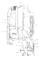
図1〜3に示すように、汎用コンバインは、機体フレーム2の下側に土壌面を走行する左右一対のクローラからなる走行装置3を設け、機体フレーム2の上側に脱穀・選別処理を行なう脱穀装置4を設け、脱穀装置4の前側に圃場の穀稈を収穫する刈取前処理装置5を設けている。
As shown in FIGS. 1 to 3, the general-purpose combiner is provided with a
脱穀装置4で脱穀・選別処理された穀粒は、脱穀装置4の右側に設けたグレンタンク6に貯留され、貯留された穀粒は、揚穀用排出筒と排出用排出筒からなる排出筒7によって外部へ排出される。また、グレンタンク6の前側には、操縦者が搭乗する操縦部8を設けている。
The grain that has been threshed and selected by the
<刈取前処理装置>
図1〜3に示すように、刈取前処理装置5は、フィーダハウス5Aと、オーガ装置5Bと、刈刃装置5Cと、掻込み装置5Dから構成されており、必要に応じてオーガ装置5Bの未刈取り側である左壁の上側に略上下方向に延在する縦刈刃装置を設けることもできる。
<Cutting pretreatment device>
As shown in FIGS. 1 to 3, the pre-cutting processing device 5 includes a
フィーダハウス5Aは、オーガ装置5Bによって寄集められた稲、麦、大豆、そば等の穀稈を脱穀装置4に搬送する装置であり、オーガ装置5Bと脱穀装置4の間に設けている。また、図4に示すように、フィーダハウス5Aの前部は、フィーダハウス用の昇降シリンダ11を駆動することによってフィーダハウス5Aの後部を回転自在に支持する支軸10を中心として上下方向に昇降することができる。
The feeder house 5 </ b> A is a device that conveys cereal grains such as rice, wheat, soybeans, and buckwheat collected by the auger device 5 </ b> B to the
オーガ装置5Bは、掻込み装置5Dで掻込まれた穀稈をオーガ装置5Bの後壁に開口された送込口の前側に寄集めてフィーダハウス5Aに引継ぐ装置であり、フィーダハウス5Aの前側に設け、機体の左右方向の幅と略同一幅に形成している。
The
刈刃装置5Cは、掻込み装置5Dで掻込まれた穀稈の株元を切断する装置であり、オーガ装置5Bの下壁の前端部に設け、側面視において前側から後側に緩やかに後上がり傾斜して形成している。
The
刈刃装置5Cの後側には、少なくとも左右方向に2分割された圃場の凹凸状態に沿って移動する接地体15を設けている。接地体15の前部は、左右方向に延在する支軸14に回転自在に支持されており、例えば、接地体15が圃場の畝を通過する場合には、接地体15の後部は、支軸14に支持された接地体15の前部を中心として上方に回動する。一方、接地体15が圃場の畝と畝の間の溝を通過する場合には、接地体15の後部は、支軸14に支持された接地体15の前部を中心として下方に回動する。また、接地体15の回動角度は、角度測定用のセンサ16によって測定されている。
On the rear side of the
後述する制御装置30は、センサ16の測定値に基づいて昇降シリンダ11を駆動して、刈刃装置5Cと圃場の間が所定の間隔になるように制御する。これにより、畝を横断しながら刈取り作業を行う横刈り作業時と畝に沿って移動しながら刈取り作業を行う縦刈り作業時において、刈刃装置5Cが圃場、特に圃場の畝に突っ込むのを低減することができる。
The control device 30 to be described later drives the elevating
掻込み装置5Dは、倒伏した穀稈、大豆やそば等の丈の低い穀稈、油菜や菜の花等の丈の高い穀稈をオーガ装置5Bに掻込む装置であり、オーガ装置5Bの上側に設けられ、オーガ装置5Bの左右方向の幅と略同一幅に形成している。
The
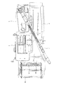
<制御装置>
次に、制御装置30の接続方法について説明する。図5に示すように、操縦部8に設けた制御装置30の入力側には、刈刃装置5Cの後側の左側に設けた左接地体15Lの回動角度を測定する左センサ16Lと、刈刃装置5Cの後側の右側に設けた右接地体15Rの回動角度を測定する右センサ16Rと、操縦部8に設けた刈取前処理装置5の昇降を手動で行う昇降レバー12の操作回数を測定するセンサ17と、走行装置2の速度を測定するセンサ18と、刈取前処理装置5の昇降操作の自動制御を開始するスイッチ19が所定の入力インターフェース回路を介して接続されている。
<Control device>
Next, a method for connecting the control device 30 will be described. As shown in FIG. 5, on the input side of the control device 30 provided in the
一方、制御装置50の出力側には、機体フレーム2と走行装置3の間に設けた機体フレーム2の左右方向の傾斜角度を調整して機体フレーム2を水平にするローリングシリンダを駆動する油圧バルブ21の回路部と、刈取前処理装置5のフィーダハウス5Aの昇降を行う昇降シリンダ11を駆動する油圧バルブ22の回路部が所定の出力インターフェース回路を介して接続されている。
On the other hand, on the output side of the
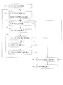
<昇降制御を停止する方法>
操縦者によってスイッチ19が入力されると、制御装置30によって自動的に機体フレーム2の左右方向の水平姿勢や、刈取前処理装置5の刈刃装置5Cと圃場の間の間隔が所定の範囲になるように制御される。しかし、刈取前処理装置5の刈刃装置5Cの後側に所定の間隔を隔てて接地体15が設けられているために、制御装置30による刈取前処理装置5の刈刃装置5Cの昇降制御が遅れて刈刃装置5Cが圃場に突っ込む恐れがあり、これを回避するために、特に畝の凹凸が激しい圃場においては、操縦者が昇降レバー12を操作して刈刃装置5Cが圃場に突っ込みを防止している。
<Method to stop lifting control>
When the switch 19 is input by the operator, the horizontal posture of the
そこで、制御装置30による刈取前処理装置5の昇降制御を中断して、操縦者の作業負担を軽減する方法について説明する。 Therefore, a method for reducing the operator's work burden by interrupting the lifting control of the pre-cutting processing device 5 by the control device 30 will be described.
図6に示すように、ステップS1において、制御装置50は、刈取前処理装置5の昇降制御を開始するスイッチ19が入力されたか否かを判断する。スイッチ19が入力されたと判断した場合はステップ2に進み。スイッチ19が入力されていないと判断した場合には昇降制御を開始しない。
As shown in FIG. 6, in step S <b> 1, the
ステップ2において、制御装置30は、操縦者が昇降レバー12を操作してセンサ17から入力される回数Nを初期値(N=0回)に設定し、制御装置30の内部タイマの時間Tを初期値(T=0秒)に設定して、ステップ3に進む。
In
ステップ3において、制御装置30は、センサ17から入力があったか否か判断する。なお、操縦者によって昇降レバー12の操作が行われた場合は、センサ17から制御装置30に入力があり、操縦者によって昇降レバー12の操作が行われなかった場合には、センサ17から制御装置30への入力はない。
In
ステップ3において、制御装置30は、センサ17からの入力があったと判断した場合は、ステップ4に進んで回数Nに1を加算した後に、ステップ5に進み回数Nが設定回数N1を超えているか否か判断する。回数Nが設定回数N1以下の場合はステップ6に進み、一方、回数Nが設定回数N1を超えている場合には、ステップ8に進む。なお、設定回数N1は作業環境に応じて任意の数に設定することができる。
In
一方、ステップ3において、センサ17からの入力が行われていないと判断した場合は、ステップS6に進んで時間Tに1を加算した後に、ステップ7に進み時間Tが設定時間T1を超えているか否か判断し、時間Tが設定時間T1以下の場合はステップ3に進み、一方、時間Tが設定時間T1を超えている場合には、ステップ2に進む。なお、設定時間T1は作業環境に応じて任意の時間に設定することができる。
On the other hand, if it is determined in
ステップ8において、制御装置30は、走行装置2の速度を測定するセンサ18の移動速度Vが設定移動速度V1以下であるか否か判断する。センサ18の移動速度Vが設定移動速度V1以下であると判断した場合は、昇降制御を停止する。一方、センサ18の移動速度Vが設定移動速度V1超であると判断した場合には、ステップ3に進む。なお、ステップ8は、任意のステップであることから、ステップ8を削除することもでき、また、設定移動速度V1は作業環境に応じて任意の速度に設定することができる。
これにより、操縦者の昇降レバー12による刈取前処理装置5の昇降操作と制御装置30による刈取前処理装置5の昇降制御が相反することに伴う操縦者の操作作業の負担を削減することができる。
In
Thereby, it is possible to reduce the burden of the operator's operation work due to the conflict between the raising / lowering operation of the cutting pretreatment device 5 by the operator's lifting
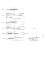
<昇降制御を再起動する方法>
次に、中断された昇降制御を再起動する方法について説明する。図7に示すように、ステップ11において、制御装置50は、昇降制御を開始するスイッチ19が入力されたか否かを判断する。スイッチ19が入力されたと判断した場合はステップ12に進み。スイッチ19が入力されていないと判断した場合には昇降制御の停止を維持する。
<How to restart lifting control>
Next, a method for restarting the suspended elevation control will be described. As shown in FIG. 7, in
ステップ12において、制御装置30は、制御装置30の第2内部タイマの停止時間tを初期値(t=0秒)に設定し、停止時間tとセンサ18の移動速度Vを乗算して算出される移動距離Lを初期値(L=0km)に設定して、ステップ13に進む。
In
ステップ13において、制御装置30は、停止時間tに1を加算した後に、ステップ14に進み停止時間tが設定停止時間t1を超えているか否か判断し、停止時間tが設定停止時間t1以下と判断した場合にステップ15に進み、一方、停止時間tが設定停止時間t1を超えている場合には、ステップ17に進んで昇降制御を再起動する。なお、設定停止時間t1は作業環境に応じて任意の時間に設定することができる。 In step 13, after adding 1 to the stop time t, the control device 30 proceeds to step 14 and determines whether or not the stop time t exceeds the set stop time t1, and the stop time t is equal to or less than the set stop time t1. If it is determined, the process proceeds to step 15. On the other hand, if the stop time t exceeds the set stop time t1, the process proceeds to step 17 to restart the lift control. The set stop time t1 can be set to an arbitrary time according to the work environment.
ステップ15において、制御装置30は、移動距離Lが設定移動距離L1を超えているか否か判断し、移動距離Lが設定移動距離L1以下と判断した場合ステップ16に進んで昇降制御の停止を維持する。一方、移動距離Lが設定移動距離L1を超えている場合には、ステップ17に進んで昇降制御を再起動する。これにより、畝の凹凸がなだらかな圃場での操縦者の操作負担を削減することができる。なお、移動距離Lは、例えば、走行装置3の駆動軸の回転を検出するセンサによりパルス出力し、そのパルス出力回数と、予め計測した1パルスあたりの機体の走行距離に基づいて算出することができる。
In
本発明は、汎用コンバインの刈取前処理装置の昇降制御の中断、再起動に利用できるものである。 INDUSTRIAL APPLICABILITY The present invention can be used for interrupting and restarting lifting control of a general-purpose combine harvesting pretreatment device.
2 機体フレーム
3 走行装置
4 脱穀装置
5 刈取前処理装置
5B オーガ装置
5C 刈刃装置
8 操縦部
11 昇降シリンダ
12 昇降レバー
15 接地体
15L 左接地体
15R 右接地体
L 移動距離
L1 設定移動距離
N 回数
N1 設定回数
t 停止時間
t1 設定停止時間
V 移動速度
V1 設定移動速度
2
Claims (5)
前記刈取前処理装置(5)のオーガ装置(5B)の下壁の前端部に刈刃装置(5C)を設け、該刈刃装置(5C)の後側に前記刈取前処理装置(5)の地上高さを検出する接地体(15)を設け、
前記接地体(15)の検出値に応じて刈取前処理装置(5)に連結された昇降シリンダ(11)を駆動して、前記刈取前処理装置(5)の地上高さを一定に維持する昇降制御を行ない、
前記操縦部(8)の昇降レバー(12)を操作して刈取前処理装置(5)を手動で上下方向に移動させた回数(N)が設定回数(N1)よりも多くなった場合に前記昇降制御を停止することを特徴とするコンバイン。 A threshing device (4) is arranged on the left side of the machine body frame (2), a pre-cutting processing device (5) of the threshing device (4) is arranged, and a control unit (8 is placed on the right side of the pre-cutting processing device (5). ), And a combine in which the traveling device (3) is disposed below the fuselage frame (2),
A cutting blade device (5C) is provided at the front end of the lower wall of the auger device (5B) of the cutting pretreatment device (5), and the cutting pretreatment device (5) is provided behind the cutting blade device (5C). A grounding body (15) for detecting the ground height is provided,
The lifting cylinder (11) connected to the pre-cutting processing device (5) is driven according to the detected value of the grounding body (15) to maintain the ground height of the pre-cutting processing device (5) constant. Control up and down,
When the number (N) of manually moving the pre-cutting processing device (5) in the vertical direction by operating the elevating lever (12) of the control unit (8) exceeds the set number (N1), The combine characterized by stopping the lifting control.
Priority Applications (1)
| Application Number | Priority Date | Filing Date | Title |
|---|---|---|---|
| JP2016033561A JP2017147976A (en) | 2016-02-24 | 2016-02-24 | Combine-harvester |
Applications Claiming Priority (1)
| Application Number | Priority Date | Filing Date | Title |
|---|---|---|---|
| JP2016033561A JP2017147976A (en) | 2016-02-24 | 2016-02-24 | Combine-harvester |
Publications (1)
| Publication Number | Publication Date |
|---|---|
| JP2017147976A true JP2017147976A (en) | 2017-08-31 |
Family
ID=59739976
Family Applications (1)
| Application Number | Title | Priority Date | Filing Date |
|---|---|---|---|
| JP2016033561A Pending JP2017147976A (en) | 2016-02-24 | 2016-02-24 | Combine-harvester |
Country Status (1)
| Country | Link |
|---|---|
| JP (1) | JP2017147976A (en) |
-
2016
- 2016-02-24 JP JP2016033561A patent/JP2017147976A/en active Pending
Similar Documents
| Publication | Publication Date | Title |
|---|---|---|
| JP5531709B2 (en) | Combine cutting height detector | |
| JP2013048605A (en) | Controller for harvesting, threshing, and driving of combine harvester | |
| JP2009183217A (en) | Working machine | |
| JP2017147976A (en) | Combine-harvester | |
| JP6345621B2 (en) | Cutting height control system for combine | |
| JP5962685B2 (en) | Combine | |
| JP7386410B2 (en) | combine | |
| JP5954478B2 (en) | Combine | |
| JP5016438B2 (en) | Mowing harvester | |
| JP2009033974A (en) | Reaping height controller of combine harvester | |
| JP6850440B2 (en) | combine | |
| JP4966274B2 (en) | Attitude control device for work equipment | |
| JP2009183216A (en) | Working machine | |
| JP2019129724A (en) | Combine | |
| JP2021119798A (en) | Combine-harvester | |
| JP2508746B2 (en) | Cutting height controller for combine harvester | |
| JP5463122B2 (en) | Working machine | |
| JP6032194B2 (en) | Combine | |
| JP3142228B2 (en) | Reaper harvester | |
| JP2021052631A (en) | combine | |
| JP2019129725A (en) | Combine | |
| JP2006075113A (en) | Combine harvester | |
| JP2012239440A (en) | Reaping height controller of combine harvester | |
| JP2002027820A (en) | Device for controlling threshing depth in combine harvester or the like | |
| JP2017099298A (en) | Combine-harvester |