JP2017146165A - Object detection system - Google Patents
Object detection system Download PDFInfo
- Publication number
- JP2017146165A JP2017146165A JP2016027164A JP2016027164A JP2017146165A JP 2017146165 A JP2017146165 A JP 2017146165A JP 2016027164 A JP2016027164 A JP 2016027164A JP 2016027164 A JP2016027164 A JP 2016027164A JP 2017146165 A JP2017146165 A JP 2017146165A
- Authority
- JP
- Japan
- Prior art keywords
- unit
- vehicle
- temperature
- information
- detection
- Prior art date
- Legal status (The legal status is an assumption and is not a legal conclusion. Google has not performed a legal analysis and makes no representation as to the accuracy of the status listed.)
- Pending
Links
Images

Abstract
Description
本発明は、物体検知システムに関する。 The present invention relates to an object detection system.
従来、超音波を用いて物体を検知する物体検知装置が知られており、たとえば特許文献1に開示されている。特許文献1に記載の物体検知装置は、超音波を送受波する超音波振動子と、超音波振動子を駆動して超音波振動子から超音波を送波させる駆動部と、超音波振動子で受波した物体からの反射波を処理する処理部とを備える。また、この物体検知装置は、駆動部を制御するとともに処理部の処理結果から物体を検知する制御部を備える。
2. Description of the Related Art Conventionally, an object detection device that detects an object using ultrasonic waves is known, and is disclosed in, for example,
ところで、上記従来例のような物体検知装置(物体検知システム)は、たとえば自動車のような車両に搭載されて用いられる。そして、車両の置かれる環境は、車両が走行することにより変化する。このため、上記従来例のような物体検知装置(物体検知システム)では、気温や湿度といった環境の変化に依らず、一定の検知範囲を確保することが望まれている。 By the way, the object detection device (object detection system) as in the above-described conventional example is mounted and used in a vehicle such as an automobile. The environment in which the vehicle is placed changes as the vehicle travels. For this reason, in the object detection device (object detection system) as in the above-described conventional example, it is desired to ensure a certain detection range regardless of environmental changes such as temperature and humidity.
本発明は、上記の点に鑑みてなされており、環境の変化に依らず一定の検知範囲を確保し易い物体検知システムを提供することを目的とする。 The present invention has been made in view of the above points, and an object of the present invention is to provide an object detection system that can easily ensure a certain detection range regardless of environmental changes.
本発明の第1の形態の物体検知システムは、検知装置と、取得部と、通信部と、処理部とを備える。前記検知装置は、検知対象となる空間に向けて超音波を送信し、前記空間内の物体からの前記超音波の反射波を受信する超音波センサを含む。前記取得部は、前記検知装置と共に車両に搭載され、前記車両の位置を表す位置情報を取得する。前記通信部は、前記位置情報をネットワークを介して通信対象に送信し、かつ、前記通信対象から送信される前記車両の位置での湿度を表す湿度情報を前記ネットワークを介して受信する。前記処理部は、前記湿度情報に基づいて前記検知装置の送信出力、受信感度、及び検知期間の少なくともいずれか1つを補正する補正処理を実行する。 The object detection system according to the first aspect of the present invention includes a detection device, an acquisition unit, a communication unit, and a processing unit. The detection device includes an ultrasonic sensor that transmits an ultrasonic wave toward a space to be detected and receives a reflected wave of the ultrasonic wave from an object in the space. The acquisition unit is mounted on a vehicle together with the detection device, and acquires position information indicating the position of the vehicle. The communication unit transmits the position information to a communication target via a network, and receives the humidity information indicating the humidity at the position of the vehicle transmitted from the communication target via the network. The processing unit executes a correction process for correcting at least one of transmission output, reception sensitivity, and detection period of the detection device based on the humidity information.
本発明の第2の形態の物体検知システムは、第1の形態において、前記通信部は、前記通信対象から送信される前記車両の位置での気温を表す温度情報を前記ネットワークを介して受信することが好ましい。前記処理部は、前記補正処理において、前記湿度情報及び前記温度情報に基づいて前記検知装置の送信出力、受信感度、及び検知期間の少なくともいずれか1つを補正することが好ましい。 In the object detection system according to a second aspect of the present invention, in the first aspect, the communication unit receives temperature information representing the temperature at the position of the vehicle transmitted from the communication target via the network. It is preferable. In the correction process, the processing unit preferably corrects at least one of the transmission output, the reception sensitivity, and the detection period of the detection device based on the humidity information and the temperature information.
本発明の第3の形態の物体検知システムは、第1又は第2の形態において、前記車両に搭載されて前記車両外の気温を検知する温度センサをさらに備えることが好ましい。前記処理部は、前記補正処理において、前記湿度情報と、前記温度センサで検知した検知温度とに基づいて前記検知装置の送信出力、受信感度、及び検知期間の少なくともいずれか1つを補正することが好ましい。 In the 1st or 2nd form, the object detection system of the 3rd form of this invention is further equipped with the temperature sensor mounted in the said vehicle and detecting the temperature outside the said vehicle. The processing unit corrects at least one of the transmission output, the reception sensitivity, and the detection period of the detection device based on the humidity information and the detected temperature detected by the temperature sensor in the correction process. Is preferred.
本発明の第4の形態の物体検知システムは、第1〜第3のいずれかの形態において、前記補正処理時の前記位置情報から基準範囲を設定する更新部をさらに備えることが好ましい。前記更新部は、前記位置情報を定期的に監視し、前記位置情報が前記基準範囲から外れると、前記補正処理を前記処理部に実行させることが好ましい。 In any one of the first to third aspects, the object detection system according to the fourth aspect of the present invention preferably further includes an update unit that sets a reference range from the position information at the time of the correction process. It is preferable that the update unit periodically monitors the position information and causes the processing unit to execute the correction process when the position information is out of the reference range.
本発明は、車両の置かれる環境の湿度に基づいて検知装置の検知範囲を補正することができる。つまり、本発明は、車両の置かれる環境に応じて検知装置の検知範囲を補正するので、環境の変化に依らず一定の検知範囲を確保し易い。 The present invention can correct the detection range of the detection device based on the humidity of the environment in which the vehicle is placed. That is, according to the present invention, the detection range of the detection device is corrected according to the environment in which the vehicle is placed. Therefore, it is easy to ensure a constant detection range regardless of changes in the environment.
以下の実施形態は、物体検知システムに関し、より詳細には、超音波を用いて物体を検知する物体検知システムに関する。 The following embodiments relate to an object detection system, and more particularly, to an object detection system that detects an object using ultrasonic waves.
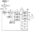
本実施形態の物体検知システム100は、図1に示すように、超音波センサ11を含む検知装置1と、取得部2と、通信部3と、処理部5とを備えている。超音波センサ11は、検知対象となる空間に向けて超音波を送信し、空間内の物体B1からの超音波の反射波を受信する。取得部2は、検知装置1と共に車両に搭載され、車両の位置を表す位置情報D1を取得する。通信部3は、位置情報D1をネットワークN1を介して通信対象C1に送信し、かつ、通信対象C1から送信される車両の位置での湿度を表す湿度情報D2をネットワークN1を介して受信する。処理部5は、湿度情報D2に基づいて検知装置1の送信出力、受信感度、及び検知期間の少なくともいずれか1つを補正する補正処理を実行する。
As illustrated in FIG. 1, the
以下、本実施形態に係る物体検知システム100について詳細に説明する。ただし、以下に説明する構成は、本発明の一例に過ぎず、本発明は下記の実施形態に限定されることはなく、この実施形態以外であっても、本発明に係る技術的思想を逸脱しない範囲であれば、設計等に応じて種々の変更が可能である。
Hereinafter, the
本実施形態の物体検知システム100は、たとえば自動車のような車両に搭載されて用いられる。以下では、車両を自動車として説明する。本実施形態の物体検知システム100は、検知対象となる空間(つまり、検知範囲A1(図2参照))における物体B1の有無を検知するシステムである。ここで、検知範囲A1は、検知装置1(超音波センサ11)から送信される超音波が届く範囲であり、かつ、検知装置1が物体B1の有無を検知可能な範囲である。また、物体B1は、たとえば人や動物のような生体の他に、車止めや電柱、ガードレール、壁のような障害物も含む。本実施形態の物体検知システム100は、たとえば車両の駐車支援システムや、車両の自動運転支援システムに用いられる。また、本実施形態の物体検知システム100は、たとえば車両がオープンカーであれば、車両への侵入検知システムにも用いることが可能である。
The
本実施形態の物体検知システム100は、図1に示すように、1乃至複数(ここでは、4つ)の超音波センサ11と、検知部12と、取得部2と、通信部3と、温度センサ4と、処理部5と、更新部6とを備えている。1乃至複数の超音波センサ11と、検知部12とは、検知装置1を構成している。
As illustrated in FIG. 1, the
超音波センサ11は、たとえば車両のバンパーに取り付けられる。一例を挙げると、超音波センサ11が4つであれば、2つの超音波センサ11が車両のフロントバンパーに取り付けられ、残りの2つの超音波センサ11が車両のリアバンパーに取り付けられる。もちろん、超音波センサ11は、物体検知システム100の用途に応じて車両に配置されてよい。超音波センサ11は、送信部111と、受信部112と、駆動部113とを備えている。
The
送信部111は、電気信号を機械的な振動に変換するように構成されている。本実施形態では、送信部111は、駆動部113から出力される所定の駆動信号によって振動し、空気を振動させることで超音波を検知対象となる空間に向けて送信(送波)する。本実施形態では、送信部111は、駆動部113からの駆動信号に従って一定間隔で超音波を送信する。すなわち、送信部111は、超音波を間欠的に送信する。 The transmission unit 111 is configured to convert an electric signal into mechanical vibration. In the present embodiment, the transmission unit 111 vibrates according to a predetermined drive signal output from the drive unit 113, and transmits (transmits) an ultrasonic wave toward a space to be detected by vibrating the air. In the present embodiment, the transmission unit 111 transmits ultrasonic waves at regular intervals according to the drive signal from the drive unit 113. That is, the transmission unit 111 transmits ultrasonic waves intermittently.
受信部112は、機械的な振動を電気信号に変換するように構成されている。本実施形態では、受信部112は、送信部111から送信された超音波のうち物体B1で反射した反射波を受信(受波)し、受信した反射波を電気信号に変換する。また、受信部112は、変換した電気信号を検知部12に出力する。
The
駆動部113は、検知部12から超音波の送信を開始させる開始指令を受け取ると、開始指令に基づいて所定の駆動信号を出力し、送信部111に超音波の送信を開始させる。また、駆動部113は、検知部12から超音波の送信を停止させる停止指令を受け取ると、停止指令に基づいて駆動信号の出力を停止し、送信部111に超音波の送信を停止させる。
Upon receiving a start command for starting transmission of ultrasonic waves from the
本実施形態では、送信部111及び受信部112は、たとえば超音波トランスデューサで一体に構成されている。また、駆動部113は、超音波トランスデューサと共に1つの筐体に収納されている。もちろん、送信部111、受信部112、及び駆動部113は、それぞれ別体に構成されていてもよい。
In the present embodiment, the transmission unit 111 and the
検知部12は、たとえばマイコン(マイクロコンピュータ)を主構成として備えている。マイコンは、そのメモリに記録されているプログラムをCPU(Central Processing Unit)で実行することにより、検知部12としての機能を実現する。プログラムは、予めマイコンのメモリに記録されていてもよいし、メモリカードのような記録媒体に記録されて提供されたり、電気通信回線を通して提供されたりしてもよい。
The
検知部12は、受信部112の出力波形に基づいて、検知範囲A1(図2参照)における物体B1の有無を検知する。また、検知部12は、送信部111が超音波を送信してから、受信部112が反射波を受信するまでの時間に基づいて、物体B1までの距離を検知する。なお、検知部12は、少なくとも検知範囲A1における物体B1の有無を検知すればよく、物体B1までの距離を検知するか否かは任意である。
Based on the output waveform of the
取得部2は、たとえばGPS(Global Positioning System)受信機で構成されている。取得部2は、車両の位置を表す位置情報D1を取得する。取得部2は、GPS受信機能を有していればよく、専用のGPS受信機で構成されていなくてもよい。たとえば、取得部2は、車両に搭載されているカーナビゲーションシステムで構成されていてもよい。この場合、取得部2は、カーナビゲーションシステムが備えるGPS受信機能を利用して、位置情報D1を取得する。また、取得部2は、たとえばレーダー探知機やドライブレコーダーで構成されていてもよい。この場合、取得部2は、レーダー探知機やドライブレコーダーが備えるGPS受信機能を利用して、位置情報D1を取得する。その他、取得部2は、たとえばスマートホンなどのGPS受信機能を備える携帯端末で構成されていてもよい。この場合、取得部2は、携帯端末が備えるGPS受信機能を利用して、位置情報D1を取得する。
The
通信部3は、いわゆるIoT(Internet of Things)技術を利用した通信ユニットである。通信部3は、通信対象C1とネットワークN1を介して無線で通信する。本実施形態では、ネットワークN1は、インターネットである。もちろん、ネットワークN1は、インターネット以外のネットワークであってもよい。通信部3は、たとえば4G(4th Generation)などの移動通信システムを利用して、無線通信を行う。通信部3は、取得部2で取得した位置情報D1を、ネットワークN1を介して通信対象C1に送信する送信処理を実行し、かつ、通信対象C1から送信される湿度情報D2及び温度情報D3を、ネットワークN1を介して受信する受信処理を実行する。ここで、湿度情報D2は、車両の位置での湿度を表す情報である。また、温度情報D3は、車両の位置での気温を表す情報である。
The
通信対象C1は、たとえば気象庁や予報業務許可事業者が提供する種々の気象情報が蓄積されているサーバである。本実施形態では、通信対象C1は、通信部3から送信される位置情報D1に基づいて、気象情報のうち、湿度情報D2及び温度情報D3を通信部3に返信する。気象情報は、気象庁や予報業務許可事業者により、定期的または不定期に更新される。もちろん、通信対象C1は、サーバに限定されず、通信部3から送信される位置情報D1に基づいて、湿度情報D2及び温度情報D3を通信部3に返信できる構成であればよい。
The communication target C1 is a server in which various types of weather information provided by, for example, the Japan Meteorological Agency or a forecast business permit business operator is accumulated. In the present embodiment, the communication target C <b> 1 returns the humidity information D <b> 2 and the temperature information D <b> 3 among the weather information to the
通信部3は、ネットワークN1を介して通信対象C1と無線で通信する機能を有していればよく、専用の通信ユニットで構成されていなくてもよい。通信部3は、たとえばスマートホンなどのネットワークN1に接続可能な携帯端末で構成されていてもよい。たとえば、通信部3がスマートホンで構成されている場合、送信処理と受信処理とを実行するアプリケーションを、スマートホンにインストールすればよい。
The
本実施形態では、通信部3は、処理部5からの指令を受けることで、送信処理と受信処理とを実行するように構成されている。もちろん、通信部3は、たとえば定期的又は不定期に、送信処理と受信処理とを実行するように構成されていてもよい。
In the present embodiment, the
温度センサ4は、たとえばNTC(Negative Temperature Coefficient)サーミスタを用いて構成され、車両外の気温を検知する。以下では、温度センサ4で検知された気温を「検知温度D4」という。温度センサ4は、気温の検知精度を高めるために、車両の排熱を受けない位置や、車両の走行中に発生する走行風を受ける位置に配置されるのが好ましい。
The
処理部5は、たとえばマイコンを主構成として備えている。マイコンは、そのメモリに記録されているプログラムをCPUで実行することにより、処理部5としての機能を実現する。プログラムは、予めマイコンのメモリに記録されていてもよいし、メモリカードのような記録媒体に記録されて提供されたり、電気通信回線を通して提供されたりしてもよい。
The
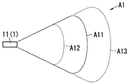
ここで、検知装置1から空気中に放出された超音波は、環境(ここでは、気温や湿度)の影響を受ける。このため、超音波の減衰特性も環境によって変化する。たとえば、空気中での超音波の減衰量は、気温の上昇や湿度の上昇と共に増加する。そして、図2に示すように、超音波の減衰量の変化に伴い、検知装置1(超音波センサ11)の検知範囲A1も変化する。以下、気温や湿度の変化による検知装置1の検知範囲A1の変化について説明する。
Here, the ultrasonic wave emitted from the
図2に示すように、基準湿度(たとえば、相対湿度40%)、基準温度(たとえば、20℃)における検知範囲A1を「検知範囲A11」とする。ここで、気温及び湿度がそれぞれ基準温度及び基準湿度よりも高くなった場合の検知範囲A1を「検知範囲A12」とすると、検知範囲A12は、基準となる検知範囲A11よりも狭くなる。また、気温及び湿度がそれぞれ基準温度及び基準湿度よりも低くなった場合の検知範囲A1を「検知範囲A13」とすると、検知範囲A13は、基準となる検知範囲A11よりも広くなる。このように、環境(ここでは、気温や湿度)に応じて超音波の減衰特性が変化するため、検知装置1の検知範囲A1も環境に応じて変化してしまい、種々の環境で一定の検知範囲A1を確保することが困難である。
As shown in FIG. 2, a detection range A1 at a reference humidity (for example, relative humidity 40%) and a reference temperature (for example, 20 ° C.) is defined as “detection range A11”. Here, assuming that the detection range A1 when the temperature and humidity are higher than the reference temperature and the reference humidity, respectively, is “detection range A12”, the detection range A12 is narrower than the reference detection range A11. Further, if the detection range A1 when the temperature and humidity are lower than the reference temperature and the reference humidity is “detection range A13”, the detection range A13 is wider than the reference detection range A11. In this way, since the attenuation characteristic of the ultrasonic wave changes according to the environment (here, temperature and humidity), the detection range A1 of the
そこで、本実施形態の物体検知システム100は、環境の変化に応じて処理部5が補正処理を実行することにより、検知装置1の検知範囲A1を、基準となる検知範囲A11に近付けるように補正している。処理部5は、湿度情報D2及び温度情報D3(又は検知温度D4)に基づいて、検知装置1のパラメータ(ここでは、送信出力、受信感度、及び検知期間の少なくともいずれか1つ)を補正する補正処理を実行する。
Therefore, the
これらのパラメータは、いずれも検知装置1の検知範囲A1を規定する要素である。送信出力は、送信部111から送信される超音波の音圧レベルである。たとえば、送信出力を大きくすることにより、超音波が届く範囲が広がる。つまり、処理部5は、送信出力を変化させることで、検知範囲A1を変化させることができる。また、受信感度は、受信部112で受信可能な超音波の音圧レベルである。たとえば、受信感度を大きくすることにより、検知装置1の遠方に位置する物体B1から飛来する反射波を受信できるようになる。つまり、処理部5は、受信感度を変化させることにより、検知範囲A1を変化させることができる。また、検知期間は、検知装置1が超音波を送信してから、反射波の受け付けを終了するまでの期間である。たとえば、検知期間を長くすることにより、検知装置1の遠方に位置する物体B1からの反射波を待ち受けることができるようになる。つまり、処理部5は、検知期間を変化させることにより、検知範囲A1を変化させることができる。
These parameters are all elements that define the detection range A1 of the
たとえば、湿度情報D2及び温度情報D3(又は検知温度D4)が表す車両の位置での気温及び湿度が、それぞれ基準温度及び基準湿度よりも高い場合、処理部5は、補正処理において、送信出力を大きくするように補正する。これにより、処理部5は、基準となる検知範囲A11に近付けるように検知範囲A1を補正することができる。
For example, when the temperature and humidity at the vehicle position represented by the humidity information D2 and the temperature information D3 (or the detected temperature D4) are higher than the reference temperature and the reference humidity, respectively, the
処理部5は、たとえば気温及び湿度と、パラメータの補正値とを対応付けた補正テーブルを記憶するように構成されていてもよい。この構成では、処理部5は、補正テーブルを参照して、湿度情報D2及び温度情報D3(又は検知温度D4)に応じた補正値を用いて、検知装置1のパラメータを補正する。なお、処理部5は、補正処理において、複数のパラメータのうちの一部(たとえば、1つ)のみを補正してもよいし、全ての複数のパラメータを補正してもよい。
The
更新部6は、たとえばマイコンを主構成として備えている。マイコンは、そのメモリに記録されているプログラムをCPUで実行することにより、更新部6としての機能を実現する。プログラムは、予めマイコンのメモリに記録されていてもよいし、メモリカードのような記録媒体に記録されて提供されたり、電気通信回線を通して提供されたりしてもよい。
The
更新部6は、処理部5が補正処理を実行したときに、補正処理時の位置情報D1に基づいて基準範囲を設定する。ここで、基準範囲は、たとえば補正処理時の車両の位置からの距離で設定される。また、基準範囲は、たとえば気温分布や湿度分布を表す地図上において、補正処理時の車両の位置での気温や湿度と同値を示す地域で設定される。そして、更新部6は、位置情報D1を定期的に監視し、位置情報D1が基準範囲から外れると、補正処理を処理部5に実行させることにより、検知装置1のパラメータを更新させる。
When the
たとえば、任意の地点で処理部5が補正処理を実行したとする。このとき、更新部6が、当該地点を中心とする半径10kmの円を基準範囲に設定したとする。その後、車両が走行することにより、車両が補正処理時の地点から10kmの位置よりも離れると、更新部6は、位置情報D1が基準範囲を外れたと判定し、補正処理を処理部5に実行させる。
For example, it is assumed that the
このとき、処理部5は、通信部3に指令を与えることで、通信部3に送信処理と受信処理とを実行させる。そして、処理部5は、最新の湿度情報D2及び温度情報D3(又は検知温度D4)を用いて、補正処理を実行する。なお、通信部3が定期的に送信処理と受信処理とを実行する構成である場合、処理部5は、通信部3の受信している最新の湿度情報D2及び温度情報D3(又は検知温度D4)を用いて、補正処理を実行する。
At this time, the
本実施形態では、検知部12、処理部5、及び更新部6は、車両に搭載されている第1電子制御ユニット(ECU:Electronic Control Unit)7に組み込まれている。もちろん、検知部12、処理部5、及び更新部6は、それぞれ第1電子制御ユニット7とは別体に構成されていてもよい。
In this embodiment, the
また、本実施形態では、取得部2、通信部3及び温度センサ4は、それぞれ第1電子制御ユニット7とは異なる第2電子制御ユニット8に電気的に接続されている。第2電子制御ユニット8は、たとえばCAN(Controller Area Network)を介して第1電子制御ユニット7に電気的に接続されている。つまり、取得部2、通信部3、及び温度センサ4は、それぞれ第2電子制御ユニット8を介して第1電子制御ユニット7に電気的に接続されている。もちろん、取得部2、通信部3、及び温度センサ4は、第1電子制御ユニット7に直接、電気的に接続されていてもよい。
In the present embodiment, the
以下、本実施形態の物体検知システム100の動作について図3を用いて説明する。まず、運転者がイグニッションキーを用いて車両を始動させる。すると、処理部5は、検知装置1のパラメータを初期化する(ステップS1)。次に、処理部5は、通信部3に指令を与えることで、通信部3に送信処理と受信処理とを実行させる。指令を受けた通信部3は、取得部2が取得した位置情報D1を通信対象C1に送信する(ステップS2)。その後、通信部3は、通信対象C1から送信される湿度情報D2及び温度情報D3を受信する(ステップS3)。
Hereinafter, the operation of the
そして、処理部5は、車両の走行距離と閾値(たとえば、1km)とを比較する(ステップS4)。走行距離が閾値未満であれば、処理部5は、温度情報D3を採用し(ステップS5)、湿度情報D2及び温度情報D3を用いて補正処理を実行する(ステップS7)。走行距離が閾値以上であれば、処理部5は、検知温度D4を採用し(ステップS6)、湿度情報D2及び検知温度D4を用いて補正処理を実行する(ステップS7)。ここでは、車両が始動した直後であるため、走行距離は閾値未満である可能性が高い。
Then, the
補正処理の実行後、更新部6は、補正処理時の位置情報D1に基づいて基準範囲を設定する(ステップS8)。そして、更新部6は、定期的に位置情報D1を監視し、位置情報D1が基準範囲外であるか否かを判定する(ステップS9)。位置情報D1が基準範囲内であれば、更新部6は、処理部5にステップS4〜ステップS7の処理を実行させる。以下、位置情報D1が基準範囲外となるまで、ステップS4〜ステップS8の処理が繰り返される。なお、位置情報D1が基準範囲外となるまでは、ステップS8は省略してもよい。
After executing the correction process, the
位置情報D1が基準範囲外になると、更新部6は、処理部5に補正処理を再度実行させる。つまり、位置情報D1が基準範囲外になると、ステップS2〜ステップS8の処理が再度実行される。これにより、検知装置1のパラメータが更新される。
When the position information D1 is out of the reference range, the
上述のように、本実施形態の物体検知システム100では、通信部3は、通信対象C1から送信される車両の位置での湿度を表す湿度情報D2を、ネットワークN1を介して受信している。そして、処理部5は、通信部3で受信した湿度情報D2に基づいて、検知装置1の送信出力、受信感度、及び検知期間の少なくともいずれか1つを補正している。このため、本実施形態の物体検知システム100は、車両の置かれる環境での湿度に基づいて検知装置1の検知範囲A1を補正することができる。つまり、本実施形態の物体検知システム100は、車両の置かれる環境に応じて検知装置1の検知範囲A1を補正するので、環境の変化に依らず一定の検知範囲A1を確保し易い。たとえば、基準湿度よりも湿度の低い地域での検知範囲A1と、基準湿度よりも湿度の高い地域での検知範囲A1とを、基準となる検知範囲A11と同等の範囲に補正することが可能である。
As described above, in the
また、本実施形態の物体検知システム100は、専用の湿度センサを車両に備える必要がないので、容易に構築することが可能である。さらに、本実施形態の物体検知システム100は、たとえば取得部2及び通信部3を車両に標準搭載されている機器やスマートホンで構成すれば、専用のGPS受信機や通信ユニットを備える必要がないので、より容易に構築することが可能である。
In addition, the
また、本実施形態の物体検知システム100では、通信部3は、通信対象C1から送信される車両の位置での気温を表す温度情報D3を、ネットワークN1を介して受信している。そして、処理部5は、補正処理において、湿度情報D2及び温度情報D3に基づいて検知装置1の送信出力、受信感度、及び検知期間の少なくともいずれか1つを補正している。この構成では、処理部5は、車両の置かれる環境の湿度だけではなく、車両の置かれる環境の気温も考慮して補正処理を実行するため、検知範囲A1を補正する精度を高めることができる。なお、当該構成を採用するか否かは任意である。
Moreover, in the
また、本実施形態の物体検知システム100は、車両に搭載されて車両外の気温を検知する温度センサ4をさらに備えている。そして、処理部5は、補正処理において、湿度情報D2と、温度センサ4で検知した検知温度D4とに基づいて検知装置1の送信出力、受信感度、及び検知期間の少なくともいずれか1つを補正している。この構成では、処理部5は、車両の置かれる環境の湿度だけではなく、車両外の気温も考慮して補正処理を実行するため、検知範囲A1を補正する精度を高めることができる。とくに、温度情報D3が表す気温は、車両の位置する地域の気温であるのに対して、検知温度D4は、車両の周辺の気温である。このため、処理部5は、より環境の変化に即した補正処理を実行することが可能である。なお、当該構成を採用するか否かは任意である。
The
ここで、本実施形態では、処理部5は、条件に応じて、温度情報D3及び検知温度D4のいずれか一方を採用して補正処理を実行している。具体的には、車両の走行距離が閾値未満であれば、処理部5は、温度情報D3を採用して補正処理を実行している。たとえば炎天下に車両を駐車している場合、高熱となった車両の熱が温度センサ4で検知されることにより、検知温度D4が車両外の気温よりも高くなってずれる可能性があると考えられるからである。また、走行距離が閾値以上であれば、処理部5は、検知温度D4を採用して補正処理を実行している。車両がある程度走行した状態であれば、車両も走行風により冷却されるため、検知温度D4が車両外の気温に収束すると考えられるからである。
Here, in the present embodiment, the
もちろん、処理部5は、条件に依らず、温度情報D3を用いずに検知温度D4のみを採用して補正処理を実行してもよい。この場合、通信部3は、通信対象C1から湿度情報D2のみを受信すればよい。また、処理部5は、条件に依らず、検知温度D4を用いずに温度情報D3のみを採用して補正処理を実行してもよい。この場合、温度センサ4は不要である。
Of course, the
また、本実施形態の物体検知システム100は、補正処理時の位置情報D1から基準範囲を設定する更新部6をさらに備えている。そして、更新部6は、位置情報D1を定期的に監視し、位置情報D1が基準範囲から外れると、補正処理を処理部5に実行させている。位置情報D1が基準範囲から外れると、車両の位置が補正処理時の位置から遠く離れているため、環境(ここでは、湿度や温度)も変化する可能性が高いからである。この構成では、位置情報D1が基準範囲から外れる、つまり車両の位置が補正処理時の位置から遠く離れると、処理部5が再度補正処理を実行する。このため、この構成では、車両が走行しているときに、車両の置かれる環境が変化しても、環境に応じて検知装置1の検知範囲A1を更新することができる。なお、当該構成を採用するか否かは任意である。
The
なお、本実施形態において、走行距離と閾値との比較で「以上」としているところは、2値が等しい場合と、2値の一方が他方を上回っている場合との両方を含むことを意味している。ただし、これに限らず、「以上」は、2値の一方が他方を上回っている場合のみを含む「より大きい」と同義であってもよい。つまり、2値が等しい場合を含むか否かは、閾値の設定次第で任意に変更できるので、「以上」か「より大きい」かに技術上の差異はない。 In the present embodiment, “more than” in the comparison of the travel distance and the threshold means that both the case where the two values are equal and the case where one of the two values exceeds the other are included. ing. However, the present invention is not limited thereto, and “more than” may be synonymous with “greater than” including only when one of the two values exceeds the other. That is, whether or not to include the case where the two values are equal can be arbitrarily changed depending on the setting of the threshold value, so there is no technical difference between “greater than” or “greater than”.
1 検知装置
11 超音波センサ
2 取得部
3 通信部
4 温度センサ
5 処理部
6 更新部
100 物体検知システム
B1 物体
C1 通信対象
D1 位置情報
D2 湿度情報
D3 温度情報
D4 検知温度
N1 ネットワーク
DESCRIPTION OF
Claims (4)
前記検知装置と共に車両に搭載され、前記車両の位置を表す位置情報を取得する取得部と、
前記位置情報をネットワークを介して通信対象に送信し、かつ、前記通信対象から送信される前記車両の位置での湿度を表す湿度情報を前記ネットワークを介して受信する通信部と、
前記湿度情報に基づいて前記検知装置の送信出力、受信感度、及び検知期間の少なくともいずれか1つを補正する補正処理を実行する処理部とを備えることを特徴とする物体検知システム。 A detection device including an ultrasonic sensor that transmits an ultrasonic wave toward a space to be detected and receives a reflected wave of the ultrasonic wave from an object in the space;
An acquisition unit that is mounted on a vehicle together with the detection device and acquires position information that represents the position of the vehicle;
A communication unit that transmits the position information to a communication target via a network and receives humidity information representing the humidity at the position of the vehicle transmitted from the communication target via the network;
An object detection system comprising: a processing unit that performs correction processing for correcting at least one of transmission output, reception sensitivity, and detection period of the detection device based on the humidity information.
前記処理部は、前記補正処理において、前記湿度情報及び前記温度情報に基づいて前記検知装置の送信出力、受信感度、及び検知期間の少なくともいずれか1つを補正することを特徴とする請求項1記載の物体検知システム。 The communication unit receives temperature information representing the temperature at the position of the vehicle transmitted from the communication target via the network,
The processing unit corrects at least one of transmission output, reception sensitivity, and detection period of the detection device based on the humidity information and the temperature information in the correction process. The object detection system described.
前記処理部は、前記補正処理において、前記湿度情報と、前記温度センサで検知した検知温度とに基づいて前記検知装置の送信出力、受信感度、及び検知期間の少なくともいずれか1つを補正することを特徴とする請求項1又は2に記載の物体検知システム。 A temperature sensor mounted on the vehicle for detecting the temperature outside the vehicle;
The processing unit corrects at least one of the transmission output, the reception sensitivity, and the detection period of the detection device based on the humidity information and the detected temperature detected by the temperature sensor in the correction process. The object detection system according to claim 1 or 2.
前記更新部は、前記位置情報を定期的に監視し、前記位置情報が前記基準範囲から外れると、前記補正処理を前記処理部に実行させることを特徴とする請求項1乃至3のいずれか1項に記載の物体検知システム。 An update unit for setting a reference range from the position information at the time of the correction process;
4. The update unit according to claim 1, wherein the update unit periodically monitors the position information, and causes the processing unit to execute the correction process when the position information is out of the reference range. The object detection system according to item.
Priority Applications (1)
| Application Number | Priority Date | Filing Date | Title |
|---|---|---|---|
| JP2016027164A JP2017146165A (en) | 2016-02-16 | 2016-02-16 | Object detection system |
Applications Claiming Priority (1)
| Application Number | Priority Date | Filing Date | Title |
|---|---|---|---|
| JP2016027164A JP2017146165A (en) | 2016-02-16 | 2016-02-16 | Object detection system |
Publications (1)
| Publication Number | Publication Date |
|---|---|
| JP2017146165A true JP2017146165A (en) | 2017-08-24 |
Family
ID=59681248
Family Applications (1)
| Application Number | Title | Priority Date | Filing Date |
|---|---|---|---|
| JP2016027164A Pending JP2017146165A (en) | 2016-02-16 | 2016-02-16 | Object detection system |
Country Status (1)
| Country | Link |
|---|---|
| JP (1) | JP2017146165A (en) |
Cited By (2)
| Publication number | Priority date | Publication date | Assignee | Title |
|---|---|---|---|---|
| JP2019113359A (en) * | 2017-12-21 | 2019-07-11 | アイシン精機株式会社 | Obstacle detection sensor |
| US11125874B2 (en) | 2017-12-21 | 2021-09-21 | Aisin Seiki Kabushiki Kaisha | Obstacle detection sensor |
-
2016
- 2016-02-16 JP JP2016027164A patent/JP2017146165A/en active Pending
Cited By (3)
| Publication number | Priority date | Publication date | Assignee | Title |
|---|---|---|---|---|
| JP2019113359A (en) * | 2017-12-21 | 2019-07-11 | アイシン精機株式会社 | Obstacle detection sensor |
| US11125874B2 (en) | 2017-12-21 | 2021-09-21 | Aisin Seiki Kabushiki Kaisha | Obstacle detection sensor |
| JP7020102B2 (en) | 2017-12-21 | 2022-02-16 | 株式会社アイシン | Obstacle detection sensor |
Similar Documents
| Publication | Publication Date | Title |
|---|---|---|
| US9684067B2 (en) | Sound wave sensor, correction value setting device, and distance detecting device | |
| US9764689B2 (en) | System and method for monitoring driving behavior | |
| US10336318B2 (en) | Systems and methods for vehicle park assist | |
| US9899018B2 (en) | Method, system and apparatus for addressing road noise | |
| JP6012747B2 (en) | Driving support system, method and computer program in driving support system | |
| JP6142707B2 (en) | Vehicle position correction device | |
| CN108140294B (en) | Vehicle interior haptic output | |
| KR102522611B1 (en) | System for correcting the signal of the ultrasonic sensor according to the weather conditions and method thereof | |
| JP2017096771A (en) | Object detection device and object detection method | |
| US20210312810A1 (en) | Method and apparatus for low frequency localization of surrounding vehicles | |
| JP2020067774A (en) | Information processing system, program, and information processing method | |
| US9648456B2 (en) | Mobile asset device transmission detection system and method | |
| CN105629215A (en) | Vehicle ultrasonic sensor correction method and system | |
| JP2017146165A (en) | Object detection system | |
| CN110221303B (en) | Apparatus and method for controlling vehicle based on detected object | |
| JP4013924B2 (en) | Vehicle periphery monitoring device | |
| WO2018190277A1 (en) | Periphery monitoring radar device | |
| JP6836155B2 (en) | Obstacle detection device for vehicles | |
| JP2018115957A (en) | Object detection system, correction method of ultrasonic sensor, and program | |
| JP2016191614A (en) | Obstacle detection device, method of calculating humidity correction value, and method of determining ultrasonic wave reception threshold | |
| JP2019168993A (en) | Data structure, information processing device, control method, program, and storage medium | |
| CN109213114A (en) | Mobile unit configuration method and device | |
| JP2018169366A (en) | Object detection device, object detection system, and mobile body | |
| US20160334547A1 (en) | Method and Apparatus for Localized Vehicle-Sourced Weather Observations | |
| JP6614061B2 (en) | Pedestrian position detection device |