JP2017144911A - Railway vehicle body structure - Google Patents
Railway vehicle body structure Download PDFInfo
- Publication number
- JP2017144911A JP2017144911A JP2016028834A JP2016028834A JP2017144911A JP 2017144911 A JP2017144911 A JP 2017144911A JP 2016028834 A JP2016028834 A JP 2016028834A JP 2016028834 A JP2016028834 A JP 2016028834A JP 2017144911 A JP2017144911 A JP 2017144911A
- Authority
- JP
- Japan
- Prior art keywords
- frame
- railway vehicle
- welding
- welded
- joined
- Prior art date
- Legal status (The legal status is an assumption and is not a legal conclusion. Google has not performed a legal analysis and makes no representation as to the accuracy of the status listed.)
- Granted
Links
- 238000003466 welding Methods 0.000 claims abstract description 39
- 125000006850 spacer group Chemical group 0.000 claims description 17
- 230000002787 reinforcement Effects 0.000 description 27
- 241001669679 Eleotris Species 0.000 description 10
- 239000010985 leather Substances 0.000 description 7
- 238000005304 joining Methods 0.000 description 5
- 238000010276 construction Methods 0.000 description 3
- 238000003780 insertion Methods 0.000 description 3
- 230000037431 insertion Effects 0.000 description 3
- 239000000463 material Substances 0.000 description 3
- 230000002093 peripheral effect Effects 0.000 description 3
- 238000010586 diagram Methods 0.000 description 2
- 238000009432 framing Methods 0.000 description 2
- NJPPVKZQTLUDBO-UHFFFAOYSA-N novaluron Chemical compound C1=C(Cl)C(OC(F)(F)C(OC(F)(F)F)F)=CC=C1NC(=O)NC(=O)C1=C(F)C=CC=C1F NJPPVKZQTLUDBO-UHFFFAOYSA-N 0.000 description 2
- 230000000694 effects Effects 0.000 description 1
- 238000004519 manufacturing process Methods 0.000 description 1
- 238000000034 method Methods 0.000 description 1
Images


Landscapes
- Butt Welding And Welding Of Specific Article (AREA)
Abstract
Description
本発明は、溶接組立された一対の端台枠と、車両の両端に配置された端台枠の側面を連結する一対の側ハリとを有する台枠の両側面に側構体を溶接して組み立てられる鉄道車両構体に関するものである。 The present invention assembles a side structure on both side surfaces of a frame having a pair of end frames that are assembled by welding and a pair of side ridges that connect side surfaces of the end frames disposed at both ends of the vehicle. The present invention relates to a railway vehicle structure.
従来、鉄道車両構体の底板である台枠は、車両の両端に配置された一対の端台枠の各々の側面を一対の側ハリにより連結している。端台枠は、連結器や台車等各種の機能部品を取り付けるための土台としての役割を持つため、多数の部材を溶接して強度を持つように製造されている。側ハリは、通常1本の断面が略コの字形状(四角形の1辺が開口された形状、各辺の長さは異なる場合がある。以下、同じ。)の部材であり、その両端部が一対の端台枠の側面に溶接接合される。側ハリは、多数の乗客が乗ると上下に撓む構造体であり、端台枠と比較して、強度は高くない。
特許文献1に示すように、側ハリは、略コの字状の開口空間部分が端台枠の側面を構成する側台枠に嵌め込まれている。そして、側ハリの略コの字状の両端部(略コの字状の一対の水平部の先端)と端台枠とが断続的に隅肉溶接により接合されると共に、側ハリのウエブ部(略コの字状の垂直部)と端台枠の側面とがスポット溶接されている。
Conventionally, a base frame that is a bottom plate of a railway vehicle structure connects a side surface of each of a pair of end base frames arranged at both ends of the vehicle by a pair of side sledges. Since the end stand frame has a role as a base for attaching various functional parts such as a coupler and a carriage, the end stand frame is manufactured to have strength by welding a large number of members. A side bar is usually a member having a substantially U-shaped cross section (a shape in which one side of a quadrangle is opened, and the length of each side may be different. The same applies hereinafter), and both end portions thereof. Are welded to the side surfaces of the pair of end stand frames. Side tension is a structure that bends up and down when a large number of passengers ride, and its strength is not high compared to the end stand frame.
As shown in Patent Document 1, the side bar is fitted with a side frame that forms a side surface of the end frame with a substantially U-shaped opening space. Then, the substantially U-shaped end portions of the side ribs (tips of a pair of horizontal portions of the approximately U-shape) and the end base frame are joined intermittently by fillet welding, and the side barri web portion (A substantially U-shaped vertical portion) and the side surface of the end frame are spot welded.
しかしながら、従来の鉄道車両構体には、次のような問題があった。
すなわち、端台枠は、多数の部材が溶接して製造されるので、全体に大きな歪であるうねり変形が生じるため、側台枠の側面も枕木方向(レールの幅方向)及び上下方向において直線性等の精度が良くなく、枕木方向に大きな歪であるうねり変形を有している。一方、側ハリは、ロールフォーミング材を使うことが多く、直線性等の精度の良いものがほとんどである。
直線性等の精度の良い側ハリを、枕木方向に大きな歪であるうねり変形を有する端台枠に嵌め込むとき、従来は比較的強度の低い側ハリを、強度の高い端台枠に対してハンマーで叩き込んでいる。これにより、精度の良い側ハリが、精度の良くない端台枠に倣うため側ハリの直線性等の精度が良くなくなる。
そして、側ハリの端部と端台枠とを断続的に隅肉溶接により接合すると共に、側ハリのウエブ部と端台枠の側面とを栓溶接またはリング溶接している。栓溶接とは、側ハリに小径の孔を開け、その孔を塞ぐ形で溶接するものである。リング溶接とは、大きめの孔を開け、孔の内周部と端台枠の側面とを溶接するものである。
However, the conventional railway vehicle structure has the following problems.
That is, since the end frame is manufactured by welding a large number of members, undulation deformation, which is a large distortion, is generated as a whole. Therefore, the side surface of the side frame is also straight in the sleeper direction (rail width direction) and the vertical direction. The accuracy of the property and the like is not good, and there is a swell deformation that is a large strain in the sleeper direction. On the other hand, the side tension often uses a roll forming material, and most of them have high accuracy such as linearity.
When fitting a high-precision side tension such as linearity into an end stand frame that has swell deformation that is a large strain in the direction of sleepers, a relatively low side strength is conventionally compared to a high strength end stand frame. I hit it with a hammer. As a result, the high-precision side elasticity follows the inaccurate end stand frame, so the precision of the side elasticity and the like becomes poor.
Then, the end portion of the side edge and the end frame are joined intermittently by fillet welding, and the web portion of the side edge and the side surface of the end frame are plug welded or ring welded. In the plug welding, a small-diameter hole is formed in the side edge, and the hole is welded in a closed shape. Ring welding is to open a large hole and weld the inner periphery of the hole to the side surface of the end frame.
このため、せっかく精度よく製造されていた側ハリが、端台枠に合されるため、端台枠の大きな歪であるうねり変形の影響をそのまま受けて、側ハリの枕木方向に大きな歪であるうねり変形が生じる問題があった。その後、図7に示すように、側ハリの14、15側面に側構体31、32が溶接され鉄道車両構体30が製造される。そして、鉄道車両構体内部の座席組立体40、吊り革用パイプ組立体41等の付属物の内装工事が行われる。
側ハリ14、15に大きな歪であるうねり変形があると、側構体31、32にも歪が発生し、座席、吊り革用パイプ等の付属物の内装工事において、段差補正のための部材を追加挿入する等の調整作業が必要となるため、内装工事の作業効率を低下させ、全体としてコストアップする問題があった。
For this reason, since the side tension that has been manufactured with great accuracy is fitted to the end stand frame, it is directly affected by the undulation deformation that is a large distortion of the end stand frame, and is greatly strained in the direction of the sleepers of the side tension. There was a problem that swell deformation occurred. Thereafter, as shown in FIG. 7, the
If the
本発明は、上記課題を解決して、端台枠に側ハリを溶接で接合したときに、直線性等の精度の良い側ハリの形状を維持できる台枠構造を有する鉄道車両構体を提供することを目的とする。 The present invention solves the above-described problems and provides a railcar structure having a base frame structure that can maintain the shape of the side bar with high accuracy such as linearity when the side bar is joined to the end base frame by welding. For the purpose.
上記目的を達成するために、本発明の鉄道車両構体は、次の構成を有している。
(1)溶接組立された一対の端台枠と、車両の両端に配置された端台枠の側面を連結する一対の側ハリとを有する台枠の両側面に側構体を溶接して組み立てられる鉄道車両構体において、端台枠の側面に、四角形の1辺が開口された形状の側ハリが嵌め込まれて溶接接合されていること、端台枠の外側面と、側ハリの内側面と間に隙間が形成されており、端台枠の外側面と側ハリ内側面とが接触していないこと、を特徴とする。
(2)(1)に記載する鉄道車両構体において、前記端台枠の外側面または前記側ハリの内側面に取り付けたスペーサを有すること、を特徴とする。
(3)(1)または(2)に記載する鉄道車両構体において、前記側ハリの端部と前記端台枠とが連続隅肉溶接により接合されていること、を特徴とする。側ハリの端部とは、略コの字状の一対の水平部の先端をいう。ここで、強度が十分確保される箇所においては、断続隅肉溶接としても良い。
In order to achieve the above object, the railway vehicle structure of the present invention has the following configuration.
(1) It is assembled by welding side structures to both side surfaces of a frame having a pair of end frames that are assembled by welding and a pair of side frames that connect side surfaces of the end frames arranged at both ends of the vehicle. In a railway vehicle structure, a side bar having a shape in which one side of a quadrilateral is opened is welded and joined to the side surface of the end frame, and between the outer side surface of the end frame and the inner side surface of the side frame. A gap is formed in the outer frame, and the outer side surface of the end frame and the inner side surface of the side frame are not in contact with each other.
(2) The railway vehicle structure described in (1) is characterized by having a spacer attached to the outer side surface of the end stand frame or the inner side surface of the side frame.
(3) In the railway vehicle structure described in (1) or (2), an end of the side edge and the end frame are joined by continuous fillet welding. The ends of the side edges are the ends of a pair of horizontal parts that are substantially U-shaped. Here, in locations where sufficient strength is ensured, intermittent fillet welding may be used.
本発明の鉄道車両構体は、次のような作用、効果を奏する。
(1)溶接組立された一対の端台枠と、車両の両端に配置された端台枠の側面を連結する一対の側ハリとを有する台枠の両側面に側構体を溶接して組み立てられる鉄道車両構体において、端台枠の側面に、四角形の1辺が開口された形状の側ハリが嵌め込まれて溶接接合されていること、端台枠の外側面と、側ハリの内側面と間に隙間が形成されており、端台枠の外側面と側ハリ内側面とが接触していないこと、を特徴とするので、精度よく製造されていた側ハリが、端台枠に合されたときに、端台枠の枕木方向の外側面と、側ハリ内側面とが接触しないため、側ハリの枕木方向に大きなうねり変形が生じることがない。その後、側ハリの外側面に側構体が溶接され鉄道車両構体が製造される。そして、鉄道車両構体内部の座席、吊り革用パイプ等の付属物の内装工事が行われる。
側ハリに大きな歪であるうねり変形がないため、側構体に歪が発生することが少なく、座席、吊り革用パイプ等の付属物の内装工事において、段差補正のための部材を追加挿入する等の調整作業を必要としないため、内装工事の作業効率を高め、また、出来栄えも向上することができ、全体として品質の向上とコストダウンを実現できる。
The railway vehicle structure of the present invention has the following operations and effects.
(1) It is assembled by welding side structures to both side surfaces of a frame having a pair of end frames that are assembled by welding and a pair of side frames that connect side surfaces of the end frames arranged at both ends of the vehicle. In a railway vehicle structure, a side bar having a shape in which one side of a quadrilateral is opened is welded and joined to the side surface of the end frame, and between the outer side surface of the end frame and the inner side surface of the side frame. Is formed so that the outer side surface of the end frame and the inner side surface of the side frame are not in contact with each other. Sometimes, the outer side surface of the end stand frame in the sleeper direction and the inner side surface of the side spring do not come into contact with each other. Thereafter, the side structure is welded to the outer side surface of the side edge to manufacture the railway vehicle structure. Then, interior work of accessories such as seats inside the railway vehicle structure and pipes for hanging leather is performed.
Since there is no undulation deformation, which is a large distortion on the side, the side structure is less likely to be distorted, and in the interior work of accessories such as seats and pipes for hanging leather, additional members for level difference correction are inserted. Since no adjustment work is required, the work efficiency of the interior work can be increased and the workmanship can be improved. As a result, the quality can be improved and the cost can be reduced as a whole.
(2)(1)に記載する鉄道車両構体において、前記端台枠の外側面または前記側ハリの内側面に取り付けたスペーサを有すること、を特徴とするので、端台枠の外側面と側ハリの内側面とが、スペーサ取付部のみ、スペーサを介して接合されるため、スペーサのない部分では、端台枠の外側面と側ハリの内側面との間に隙間を確実に設けることができ、直線性等の精度よく製造されていた側ハリが、端台枠に合されたときに、端台枠の枕木方向の大きな歪であるうねり変形の凸部と、側ハリ内側面とが接触することがないため、側ハリの枕木方向に大きな歪であるうねり変形が生じることがない。 (2) The railcar structure described in (1) is characterized by having a spacer attached to the outer side surface of the end stand frame or the inner side surface of the side frame. Only the spacer mounting part is joined to the inner side surface of the spacer via the spacer, so that a gap can be reliably provided between the outer side surface of the end frame and the inner side surface of the side frame in the portion without the spacer. When the side tension that has been manufactured with high accuracy such as linearity is fitted to the end stand frame, the convex portion of the undulation deformation that is a large distortion in the sleeper direction of the end stand frame and the inner side surface of the side tension are Since there is no contact, undulation deformation that is a large strain does not occur in the direction of the sleeper of the side tension.
(3)(1)または(2)に記載する鉄道車両構体において、前記側ハリの端部と前記端台枠とが連続隅肉溶接により接合されていること、を特徴とする。
従来、側ハリの端部と端台枠とを断続的に隅肉溶接により接合すると共に、側ハリのウエブ部と端台枠の側面とを栓溶接またはリング溶接している。
本発明では、側ハリのウエブ部と端台枠の側面とを栓溶接またはリング溶接を行っていないが、側ハリの端部と端台枠とを連続的に隅肉溶接により接合しているので、十分な接合強度を得ることができる。
(3) In the railway vehicle structure described in (1) or (2), an end of the side edge and the end frame are joined by continuous fillet welding.
Conventionally, the end portion of the side edge and the end frame are joined intermittently by fillet welding, and the web portion of the side edge and the side surface of the end frame are plug welded or ring welded.
In the present invention, the web portion of the side edge and the side surface of the end frame are not plug welded or ring welded, but the end portion of the side edge and the end frame are continuously joined by fillet welding. Therefore, sufficient bonding strength can be obtained.
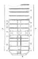
本発明の鉄道車両構体30の一実施の形態について、図面を参照しながら、詳細に説明する。図1(a)に、鉄道車両構体30の底板を形成する台枠1の平面図を示し、(b)にその側面図を示す。また、図2には、台枠1の組立前の分解図を示す。また、図3には、第1端台枠11付近の拡大図を示す。図4には、第1端台枠11付近の台枠1の組立前の分解図を示す。
台枠1は、溶接組立された一対の端台枠である第1端台枠11、第2端台枠12と、車両の両端に配置された第1端台枠11、第2端台枠12の側面を連結する一対の側ハリである左側ハリ15、右側ハリ14を有する
An embodiment of a
The underframe 1 includes a
図2に示すように、第1端台枠11は、先頭車両の先端部を構成するものであり、枕木方向の枠を構成する先頭端ハリ114と横ハリ115とが、車両の両側面方向において、レール方向の枠を構成する右側ハリ補強116と左側ハリ補強117とで溶接接合されている。中央部でも2本の中ハリ113により溶接接合されている。
第1端台枠11の中央より後寄りに枕木方向に平行に配置された横枠である枕ハリ111が、右側ハリ補強116、左側ハリ補強117、中ハリ113の各々に対して溶接接合されている。枕ハリ111は、図示しない台車枠と空気バネ等を介して連結される部位であり、鉄道車両構体30を支えるだけの高い強度を有している。
また、6本の床受ハリ112の両端が、右側ハリ補強116、左側ハリ補強117に溶接接合され、床受ハリ112の中央部が、中ハリ113に溶接接合されている。
As shown in FIG. 2, the
A
In addition, both ends of the six
また、図2に示すように、第2端台枠12は、先頭車両の後端部を構成するものであり、枕木方向の枠を構成する後端ハリ124と横ハリ125とが、車両の両側面方向において、レール方向の枠を構成する右側ハリ補強126と左側ハリ補強127とで溶接接合され、中央部でも2本の中ハリ123により溶接接合されている。
第2端台枠12の中央より前寄りに枕木方向に平行に配置された横枠である枕ハリ121が、右側ハリ補強126、左側ハリ補強127、中ハリ123の各々に対して溶接接合されている。枕ハリ121は、図示しない台車枠と空気バネ等を介して連結される部位であり、鉄道車両構体30を支えるだけの高い強度を有している。
また、6本の床受ハリ122の両端が、右側ハリ補強126、左側ハリ補強127に溶接接合され、床受ハリ122の中央部が、中ハリ123に溶接接合されている。
第1端台枠11と第2端台枠12は、各々複雑な枠材が複数の部分で溶接接合されているため、溶接熱による歪等により、右側ハリ補強116と左側ハリ補強117、右側ハリ補強126と左側ハリ補強127が、レールに垂直な方向(枕木方向)において、うねり変形を生じている。
図1に示すように、第1端台枠11と第2端台枠12との間の中間部には、18本の横ハリ13が、両端を右側ハリ14と左側ハリ15とに溶接接合され配置されている。
Further, as shown in FIG. 2, the
A
In addition, both ends of the six
Since the
As shown in FIG. 1, 18
図5に、図1のAA断面図を示す。図6に図5のA部の部分拡大図を示す。図5は、枕ハリ111の部位における断面図であり、図6は、枕ハリ111の枕木方向の端面に位置する左側ハリ補強117と、左側ハリ15との接合構造を示す図である。
図6に示すように、左側ハリ補強117は、略コの字形状であり、垂直方向に延びる側面部117aの両側に水平部117bと水平部117cが直角に曲げられて水平方向に延設されている。水平部117b、水平部117cは、枕ハリ111の端部に溶接接合されている。
左側ハリ補強117の外側には、断面が略コの字形状の左側ハリ15が嵌合されている。左側ハリ15の側面部15aの両側に水平部15bと水平部15cが直角に曲げられて水平方向に延設されている。
FIG. 5 is a cross-sectional view taken along the line AA in FIG. FIG. 6 shows a partially enlarged view of portion A in FIG. FIG. 5 is a cross-sectional view of a part of the
As shown in FIG. 6, the
On the outside of the
左側ハリ15の水平部15bの先端は、左側ハリ補強117の水平部117bの外側面に連続隅肉溶接されている。20は、連続隅肉溶接部を示す。また、左側ハリ15の水平部15cの先端は、左側ハリ補強117の水平部117cの外側面に連続隅肉溶接されている。20は、連続隅肉溶接部を示す。
左側ハリ補強117の側面部117aの外側面と、左側ハリ15の側面部15aの内周面とは、長さLの隙間を形成するように設計されている。本実施例では、L=6mmとしている。
左側ハリ補強117の側面部117aは、第1端台枠11が、多数の部材を溶接して製造されるため、全体に大きな歪であるうねり変形が生じ、左側ハリ補強117の側面部117aの外側面も枕木方向において直線形状ではなく、枕木方向に大きな歪であるうねり変形を有している。
The front end of the
The outer side surface of the
Since the
一方、左側ハリ15は、ロールフォーミング材を使うことが多く、直線性等の精度の良いものがほとんどである。
本発明者らが、かなりの数量の第1端台枠11、第2端台枠12について測定したところ、うねりの大きさは、山と谷との差異で3mm程度であり、その2倍程度のL=6mmの隙間を確保すれば、左側ハリ補強117の側面部117aの外側面と、左側ハリ15の側面部15aの内周面とが接触する恐れが全くないことを確認している。
したがって、本発明を実施するためには、隙間の長さを、4mm以上としても良いが、安全面を考えて、6mmとしている。6mmとしている理由は、左側ハリ補強117の側面部117aの外側面と、左側ハリ15の側面部15aの内周面とが接触すると、擦れ音が発生し乗客に不快感を与える可能性があり、それを回避するためである。
On the other hand, the left-
When the present inventors measured about the
Therefore, in order to carry out the present invention, the length of the gap may be 4 mm or more, but is 6 mm in consideration of safety. The reason why the width is 6 mm is that when the outer surface of the
本実施例では、左側ハリ補強117の側面部117aと、左側ハリ15の側面部15aとを栓溶接またはリング溶接を行っていないが、左側ハリ15の水平部15b、15cと第1端台枠11の左側ハリ補強117の水平部117b、117cとを連続的に隅肉溶接により接合しているので、十分な接合強度を得ることができる。
In the present embodiment, the
図7に、鉄道車両構体30の断面図を示す。図7に示すように、台枠1を構成する左側ハリ15に左側構体31がスポット溶接、もしくは栓溶接またはリング溶接により接合されている。また、同様の方法により、右側ハリ14に右側構体32が接合されている。
左側構体31、右側構体32の内面には、内壁材34,35を介して、座席組立体40がボルト等により取り付けられている。
ここで、従来のように側ハリ14、15に大きな歪であるうねり変形があると、側構体31、32にも歪が発生し、内壁材34、35を介して座席組立体40を組み付ける場合に、段差補正のための部材を追加挿入する等の調整作業が必要となる。
本実施例では、側ハリ14、15に大きなうねり変形がないため、内装工事の作業効率を低下させることがなく、また、出来栄えも向上することができ、全体として品質の向上と全体としてコストダウンできる。
FIG. 7 shows a cross-sectional view of the
A
Here, when there is a swell deformation which is a large distortion in the side burrs 14 and 15 as in the conventional case, the
In this embodiment, since the side burrs 14 and 15 do not have a large undulation deformation, the work efficiency of the interior construction work is not lowered, and the quality of the work can be improved. As a whole, the quality is improved and the cost is reduced as a whole. it can.
以上詳細に説明したように、本実施例の鉄道車両用構体によれば、
(1)溶接組立された一対の端台枠11、12と、車両の両端に配置された端台枠11、12の側面を連結する一対の側ハリ14、15とを有する台枠1の両側面に側構体を溶接して組み立てられる鉄道車両構体において、端台枠11、12の側面に、四角形の1辺が開口された形状の側ハリ14、15が嵌め込まれて溶接接合されていること、端台枠11、12の外側面と、側ハリ14、15の内側面と間に隙間(設計上の長さL)が形成されており、端台枠11、12の外側面と側ハリ14、15の内側面とが接触していないこと、を特徴とするので、精度よく製造されていた側ハリ14、15が、端台枠11、12に合されたときに、端台枠11、12の枕木方向の外側面と、側ハリ14、15の内側面とが接触することがないため、側ハリ14、15の枕木方向に大きなうねり変形が生じることがない。その後、側ハリ14、15の外側面に側構体が溶接され鉄道車両構体が製造される。そして、鉄道車両構体内部の座席組立体40、吊り革用パイプ組立体41等の付属物の内装工事が行われる。
側ハリ14、15に大きな歪であるうねり変形がないため、側構体31、32に歪が発生することが少なく、座席組立体40、吊り革用パイプ組立体41等の付属物の内装工事において、段差補正のための部材を追加挿入する等の調整作業を必要としないため、内装工事の作業効率を高め、また、出来栄えも向上することができ、全体として品質の向上と全体としてコストダウンを実現できる。
As explained in detail above, according to the railway vehicle structure of the present embodiment,
(1) Both sides of the frame 1 having a pair of end frames 11 and 12 which are assembled by welding and a pair of side frames 14 and 15 which connect the side surfaces of the end frames 11 and 12 disposed at both ends of the vehicle. In a railway vehicle structure assembled by welding a side structure to a surface, side shears 14 and 15 having a shape in which one side of a quadrangle is opened are fitted and welded to the side surfaces of the end stand frames 11 and 12. A gap (design length L) is formed between the outer surface of the
Since there is no undulation deformation that is a large distortion in the side burrs 14 and 15, the
(2)(1)に記載する鉄道車両構体において、側ハリ14、15の端部と端台枠11、12とが連続隅肉溶接により接合されていること、を特徴とする。
従来、側ハリ14、15の端部と端台枠11、12とを断続的に隅肉溶接により接合すると共に、側ハリ14、15のウエブ部(垂直部)と端台枠11、12の側面とを栓溶接またはリング溶接している。
本実施例では、側ハリ14、15のウエブ部と端台枠の側面とを栓溶接またはリング溶接を行っていないが、側ハリ14、15の端部と端台枠11、12とを連続的に隅肉溶接により接合しているので、十分な接合強度を得ることができる。本発明者は、側ハリ14、15の端部と端台枠11、12とを連続的に隅肉溶接により接合しているので、十分な接合強度を得られることを確認している。
(2) In the railway vehicle structure described in (1), the end portions of the side burrs 14 and 15 and the end frame frames 11 and 12 are joined by continuous fillet welding.
Conventionally, the end portions of the side burrs 14 and 15 and the end frame frames 11 and 12 are joined intermittently by fillet welding, and the web portion (vertical portion) of the side burrs 14 and 15 and the end frame frames 11 and 12 are joined. The side is plug welded or ring welded.
In this embodiment, the web portions of the side burrs 14 and 15 and the side surfaces of the end frame are not plug welded or ring welded, but the end portions of the side burrs 14 and 15 and the
次に、第2の実施例について説明する。図8に、第2の実施例の図4に対応する図を示す。第2の実施例は、一部を除いて、第1の実施例と同じなので、相違する点についてのみ説明し、同じ部分については、説明を割愛する。
図8に示すように、第1端台枠11のハリ補強116、117の側面部116a、117aの外側面に、厚み6mmのスペーサ51が各々の側に3個ずつ溶接により取り付けられている。図示しないが、第2端台枠12についても、同様のスペーサ51を設けている。
これにより、端台枠11、12の外側面と、側ハリ14、15の内側面と間に確実に隙間(設計上の長さL)を形成することができ、端台枠11、12の外側面と側ハリ14、15の内側面とがスペーサ51を介して接合されている部分以外で接触することがない。
本実施例では、端台枠11、12側にスペーサを固定したが、側ハリ14、15の内側面にスペーサを固定しても良い。
Next, a second embodiment will be described. FIG. 8 shows a diagram corresponding to FIG. 4 of the second embodiment. Since the second embodiment is the same as the first embodiment except for a part thereof, only differences will be described, and description of the same portions will be omitted.
As shown in FIG. 8, three
Thereby, a gap (designed length L) can be reliably formed between the outer surface of the
In this embodiment, the spacers are fixed to the end frame frames 11 and 12, but the spacers may be fixed to the inner side surfaces of the side burrs 14 and 15.
(3)(1)に記載する鉄道車両構体において、端台枠11、12の外側面または側ハリ14、15の内側面に取り付けたスペーサ51を有すること、を特徴とするので、端台枠11、12の外側面と側ハリ14、15の内側面とが、スペーサ取付部のみ、スペーサ51を介して接合されるため、スペーサ51のない部分では、端台枠11、12の外側面と側ハリの内側面との間に隙間を確実に設けることができ、直線性等の精度よく製造されていた側ハリ14、15が、端台枠11、12に合されたときに、端台枠11、12の枕木方向の大きな歪であるうねり変形の凸部と、側ハリ14、15の内側面とが接触することがないため、側ハリ14、15の枕木方向に大きな歪であるうねり変形が生じることがない。
側ハリ14、15に大きな歪であるうねり変形がないため、側構体に歪が発生することが少なく、座席組立体40、吊り革用パイプ組立体41等の付属物の内装工事において、段差補正のための部材を追加挿入する等の調整作業が必要としないため、内装工事の作業効率を高め、また、出来栄えも向上することができ、全体として品質の向上と全体としてコストダウンを実現できる。
(3) The railcar structure described in (1) is characterized by having the
Since there is no swell deformation, which is a large distortion, on the side burrs 14 and 15, the side structure is less likely to be distorted. In interior work of accessories such as the
本発明の鉄道車両構体については、上記実施の形態に限定されることなく、色々な応用が可能である。
例えば、本実施例では、側ハリ14、15の端部と端台枠11、12とが連続隅肉溶接により接合しているが、強度に問題がない範囲で、部分的に隅肉溶接を行わない部位を設けても良い。
また、本実施例では、先頭車の場合を説明したが、両方の端台枠が略同一の場合(中間車)に用いることができることは言うまでもない。中間車によっては、両方の端台枠の形状が相違する場合もあるが、その場合にも適用できる。
The railway vehicle structure of the present invention is not limited to the above embodiment, and various applications are possible.
For example, in this embodiment, the end portions of the side burrs 14 and 15 and the end base frames 11 and 12 are joined by continuous fillet welding, but the fillet welding is partially performed within a range where there is no problem in strength. You may provide the site | part which is not performed.
Further, in the present embodiment, the case of the leading car has been described, but it goes without saying that it can be used when both end stand frames are substantially the same (intermediate car). Depending on the intermediate car, the shape of both end stand frames may be different, but this is also applicable in that case.
11 第1端台枠
12 第2端台枠
14 右側ハリ
15 左側ハリ
15a 側面部
20 連続隅肉溶接部
51 スペーサ
117 左側ハリ補強
117a 側面部
11
Claims (3)
前記端台枠の側面に、四角形の1辺が開口された形状の前記側ハリが嵌め込まれて溶接接合されていること、
前記端台枠の外側面と、前記側ハリの内側面と間に隙間が形成されており、前記端台枠の外側面と前記側ハリ内側面とが接触していないこと、
を特徴とする鉄道車両構体。 A railway vehicle that is assembled by welding side structures to both side surfaces of a frame having a pair of end frames that are assembled by welding and a pair of side ridges that connect the side surfaces of the end frame disposed at both ends of the vehicle. In the structure,
The side burrs of the shape in which one side of the quadrangle is opened are welded and joined to the side surface of the end stand frame,
A gap is formed between the outer surface of the end frame and the inner surface of the side frame, and the outer surface of the end frame and the inner surface of the side frame are not in contact with each other.
A railway vehicle structure characterized by
前記端台枠の外側面または前記側ハリの内側面に取り付けたスペーサを有すること、
を特徴とする鉄道車両構体。 In the railway vehicle structure according to claim 1,
Having a spacer attached to the outer surface of the end frame or the inner surface of the side frame;
A railway vehicle structure characterized by
前記側ハリの端部と前記端台枠とが連続隅肉溶接により接合されていること、
を特徴とする鉄道車両構体。 In the railway vehicle structure according to claim 1 or claim 2,
The end of the side edge and the end frame are joined by continuous fillet welding,
A railway vehicle structure characterized by
Priority Applications (1)
| Application Number | Priority Date | Filing Date | Title |
|---|---|---|---|
| JP2016028834A JP6647907B2 (en) | 2016-02-18 | 2016-02-18 | Railcar structure |
Applications Claiming Priority (1)
| Application Number | Priority Date | Filing Date | Title |
|---|---|---|---|
| JP2016028834A JP6647907B2 (en) | 2016-02-18 | 2016-02-18 | Railcar structure |
Publications (2)
| Publication Number | Publication Date |
|---|---|
| JP2017144911A true JP2017144911A (en) | 2017-08-24 |
| JP6647907B2 JP6647907B2 (en) | 2020-02-14 |
Family
ID=59681116
Family Applications (1)
| Application Number | Title | Priority Date | Filing Date |
|---|---|---|---|
| JP2016028834A Active JP6647907B2 (en) | 2016-02-18 | 2016-02-18 | Railcar structure |
Country Status (1)
| Country | Link |
|---|---|
| JP (1) | JP6647907B2 (en) |
Cited By (4)
| Publication number | Priority date | Publication date | Assignee | Title |
|---|---|---|---|---|
| CN108602520A (en) * | 2016-02-17 | 2018-09-28 | 奥地利西门子公司 | Vehicle body for riding rail vehicle |
| CN110304091A (en) * | 2019-07-16 | 2019-10-08 | 中车株洲电力机车有限公司 | A kind of rail vehicle and its Undercarriage structure |
| CN115416710A (en) * | 2022-09-15 | 2022-12-02 | 中车青岛四方机车车辆股份有限公司 | Underframe structure and railway vehicle |
| CN117922624A (en) * | 2024-03-21 | 2024-04-26 | 成都中车长客轨道车辆有限公司 | Rail transit vehicle underframe structure and processing method |
Citations (6)
| Publication number | Priority date | Publication date | Assignee | Title |
|---|---|---|---|---|
| JPS482804Y1 (en) * | 1969-01-31 | 1973-01-24 | ||
| JPS5873067U (en) * | 1981-11-11 | 1983-05-17 | 近畿車輛株式会社 | Railway vehicle body |
| JPH02290771A (en) * | 1988-06-06 | 1990-11-30 | Hitachi Ltd | Car body of railroad rolling stock and manufacture thereof |
| JP2002145060A (en) * | 2000-11-07 | 2002-05-22 | Kinki Sharyo Co Ltd | Bolster-floor joining structure in underframe of railway rolling stock |
| JP2008230320A (en) * | 2007-03-19 | 2008-10-02 | Nippon Sharyo Seizo Kaisha Ltd | Railroad vehicle |
| JP2013212762A (en) * | 2012-04-02 | 2013-10-17 | Kawasaki Heavy Ind Ltd | Railway vehicle |
-
2016
- 2016-02-18 JP JP2016028834A patent/JP6647907B2/en active Active
Patent Citations (6)
| Publication number | Priority date | Publication date | Assignee | Title |
|---|---|---|---|---|
| JPS482804Y1 (en) * | 1969-01-31 | 1973-01-24 | ||
| JPS5873067U (en) * | 1981-11-11 | 1983-05-17 | 近畿車輛株式会社 | Railway vehicle body |
| JPH02290771A (en) * | 1988-06-06 | 1990-11-30 | Hitachi Ltd | Car body of railroad rolling stock and manufacture thereof |
| JP2002145060A (en) * | 2000-11-07 | 2002-05-22 | Kinki Sharyo Co Ltd | Bolster-floor joining structure in underframe of railway rolling stock |
| JP2008230320A (en) * | 2007-03-19 | 2008-10-02 | Nippon Sharyo Seizo Kaisha Ltd | Railroad vehicle |
| JP2013212762A (en) * | 2012-04-02 | 2013-10-17 | Kawasaki Heavy Ind Ltd | Railway vehicle |
Cited By (7)
| Publication number | Priority date | Publication date | Assignee | Title |
|---|---|---|---|---|
| CN108602520A (en) * | 2016-02-17 | 2018-09-28 | 奥地利西门子公司 | Vehicle body for riding rail vehicle |
| US10906563B2 (en) | 2016-02-17 | 2021-02-02 | Siemens Mobility Austria Gmbh | Car body for a passenger rail vehicle |
| CN110304091A (en) * | 2019-07-16 | 2019-10-08 | 中车株洲电力机车有限公司 | A kind of rail vehicle and its Undercarriage structure |
| CN115416710A (en) * | 2022-09-15 | 2022-12-02 | 中车青岛四方机车车辆股份有限公司 | Underframe structure and railway vehicle |
| CN115416710B (en) * | 2022-09-15 | 2023-09-26 | 中车青岛四方机车车辆股份有限公司 | Chassis structure and rail vehicle |
| CN117922624A (en) * | 2024-03-21 | 2024-04-26 | 成都中车长客轨道车辆有限公司 | Rail transit vehicle underframe structure and processing method |
| CN117922624B (en) * | 2024-03-21 | 2024-06-11 | 成都中车长客轨道车辆有限公司 | Rail transit vehicle underframe structure and processing method |
Also Published As
| Publication number | Publication date |
|---|---|
| JP6647907B2 (en) | 2020-02-14 |
Similar Documents
| Publication | Publication Date | Title |
|---|---|---|
| JP2017144911A (en) | Railway vehicle body structure | |
| US20130140868A1 (en) | Discontinuous section tower tube | |
| JP2006290027A (en) | Vehicle body structure | |
| JP5899913B2 (en) | Bogie frame for railcar and manufacturing method, and bogie equipped with the bogie frame | |
| CN110155097B (en) | Draw beam structure, end underframe with draw beam structure and railway vehicle | |
| JP2008230320A (en) | Railroad vehicle | |
| JP6343435B2 (en) | Lightweight body structure of railway vehicles | |
| JP5372861B2 (en) | Railcar frame structure | |
| JP4556836B2 (en) | Railcar bogie | |
| JP5977052B2 (en) | Rail vehicle skirt fixing structure | |
| JP4356540B2 (en) | Railcar bogie frame and railcar bogie | |
| JP4979390B2 (en) | Vehicle structure | |
| JP2012240542A (en) | Railroad vehicle | |
| JP2002347620A (en) | Bogie frame for railway rolling stock, assembling method therefor and bogie for railway rolling stock | |
| JP2006193129A (en) | Method for manufacturing truck frame for rolling stock, and truck frame | |
| JP2012176653A (en) | Platform truck frame for rolling stock | |
| JPH101068A (en) | Member joining structure for framed vehicle body | |
| JPH05262225A (en) | Manufacture of truck frame for railway rolling stock | |
| WO2018225442A1 (en) | Bolster beam for railway vehicle bogie | |
| CN102485566A (en) | Traction sleeper for tank car | |
| JP2010083214A (en) | Railroad vehicle and method of manufacturing railroad vehicle | |
| JP2023039706A (en) | Railway vehicle | |
| JP4731900B2 (en) | Bogie frame for railway vehicles | |
| CN211468436U (en) | Double transverse seat framework of railway vehicle | |
| JP2021070421A (en) | Railway vehicle |
Legal Events
| Date | Code | Title | Description |
|---|---|---|---|
| A621 | Written request for application examination |
Free format text: JAPANESE INTERMEDIATE CODE: A621 Effective date: 20190107 |
|
| A131 | Notification of reasons for refusal |
Free format text: JAPANESE INTERMEDIATE CODE: A131 Effective date: 20191105 |
|
| A977 | Report on retrieval |
Free format text: JAPANESE INTERMEDIATE CODE: A971007 Effective date: 20191031 |
|
| A521 | Request for written amendment filed |
Free format text: JAPANESE INTERMEDIATE CODE: A523 Effective date: 20191226 |
|
| TRDD | Decision of grant or rejection written | ||
| A01 | Written decision to grant a patent or to grant a registration (utility model) |
Free format text: JAPANESE INTERMEDIATE CODE: A01 Effective date: 20200114 |
|
| A61 | First payment of annual fees (during grant procedure) |
Free format text: JAPANESE INTERMEDIATE CODE: A61 Effective date: 20200115 |
|
| R150 | Certificate of patent or registration of utility model |
Ref document number: 6647907 Country of ref document: JP Free format text: JAPANESE INTERMEDIATE CODE: R150 |
|
| R250 | Receipt of annual fees |
Free format text: JAPANESE INTERMEDIATE CODE: R250 |