JP2017144544A - Paper sheet conveying and cutting apparatus provided with mechanism for preventing sticking of cut piece of paper margin to cutter blade - Google Patents
Paper sheet conveying and cutting apparatus provided with mechanism for preventing sticking of cut piece of paper margin to cutter blade Download PDFInfo
- Publication number
- JP2017144544A JP2017144544A JP2016039390A JP2016039390A JP2017144544A JP 2017144544 A JP2017144544 A JP 2017144544A JP 2016039390 A JP2016039390 A JP 2016039390A JP 2016039390 A JP2016039390 A JP 2016039390A JP 2017144544 A JP2017144544 A JP 2017144544A
- Authority
- JP
- Japan
- Prior art keywords
- cutting
- blade
- piece
- blank
- cut
- Prior art date
- Legal status (The legal status is an assumption and is not a legal conclusion. Google has not performed a legal analysis and makes no representation as to the accuracy of the status listed.)
- Granted
Links
Images


Abstract
Description
本発明は、枚葉紙をその給紙方向を横切る方向(以下、給紙横方向と称す)、もしくは給紙方向(以下、給紙縦方向と称す)との2方向で断裁し、給紙された枚葉紙の寸法と異なる寸法の断裁紙、もしくは複数以上に分割された断裁紙を得る装置に関し、給紙横方向断裁の際に発生する余白断裁片の断裁機刃物への貼り付きを防止し、余白断裁片の排出滞留、詰まり、断裁紙への混入、を解消するための機構を備えた枚葉紙搬送断裁装置に関する。 In the present invention, a sheet is cut in two directions, a direction crossing the sheet feeding direction (hereinafter referred to as a sheet feeding lateral direction) or a sheet feeding direction (hereinafter referred to as a sheet feeding longitudinal direction), With regard to an apparatus for obtaining a cut paper having a size different from the size of the printed sheet, or a cut paper divided into a plurality of pieces, the blank cut pieces generated when the paper is cut in the lateral direction are attached to the cutting machine blade. The present invention relates to a sheet conveying and cutting apparatus having a mechanism for preventing and eliminating the discharge retention and clogging of blank cutting pieces, clogging, and mixing into cutting paper.
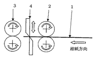
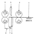
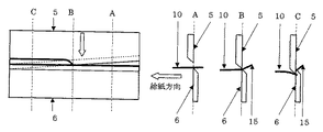
図1は断裁装置の構造を模式的に示している。従来の技術では、枚葉紙1を断裁機上流側ローラー対2で断裁機4の方向へ繰り出し、断裁機4からの繰り出し量によって断裁長さが決定され、断裁時に断裁機下流側ローラー対3で支持されていた断裁紙は、断裁後、仕上り断裁紙として断裁機下流側ローラー対3で排出される。しかし、図2に示されているように用紙先端繰り出し長さ7が下流側ローラー対/断裁機間距離8より短い場合には、余白断裁片は断裁機下流側ローラー対3で支持されることがなく、断裁完了時に余白断裁片は断裁機4と断裁機下流側ローラー対3の間に落下する。また、断裁時に枚葉紙後端が断裁機上流側ローラー対2で支持されることなく断裁機4の上流側に残っている場合には、その部分は余白断裁片として断裁機4と断裁機上流側ローラー対2の間に落下する。いずれの場合も、余白断裁片が自由落下の際に静電気引力による断裁機刃物への貼り付きを発生する恐れがあり、確実な排出を期待することは問題があって、時として余白断裁片の排紙系の詰まり、あるいは断裁紙への混入を発生することがある。 FIG. 1 schematically shows the structure of a cutting apparatus. In the conventional technique, the sheet 1 is fed out in the direction of the cutting machine 4 by the pair of
余白断裁片は断裁機4と断裁機上流側ローラー対2、もしくは断裁機下流側ローラー対3との間の間隙からの自由落下によって系外へ排出される。しかしながら、枚葉紙1の給紙横方向の断裁により断裁面に静電気が発生した場合には、断裁面の静電気引力によって余白断裁片の自由落下が阻害される恐れがある。 The blank cut pieces are discharged out of the system by free fall from a gap between the cutting machine 4 and the cutting machine
余白断裁片の質量が大きい場合にはその質量が静電気引力に打ち勝って自由落下することとなるが、その質量が小さい場合には静電気引力に打ち勝つことができずに断裁機刃物の表面に貼り付いて残留することなる。 When the mass of the blank cutting piece is large, the mass overcomes the electrostatic attraction and falls freely, but when the mass is small, the electrostatic attraction cannot be overcome and sticks to the surface of the cutter blade. Will remain.
余白断裁片の断裁機刃物表面への付着は、断裁中に静電気が帯電する断裁面が断裁機刃物刃先に吸引されることによって発生する。断裁中の余白断裁片は未断裁部分によって保持されて落下する事は無いが、断裁完了時に余白断裁片が断裁機刃物刃先に静電気吸引されている断裁面を軸としてその質量によって下方向に回転落下し、結果的に余白断裁片が断裁機下側刃物の表面に平面的に貼り付くこととなる。 Adhesion of the blank cut pieces to the cutting machine blade surface occurs when a cutting surface on which static electricity is charged is attracted to the cutting machine blade edge during cutting. The blank cut piece that is being cut is held by the uncut portion and does not fall, but when the cutting is completed, the blank cut piece is rotated downward by its mass about the cutting surface that is electrostatically attracted to the cutter edge. As a result, the blank cut piece sticks flatly to the surface of the cutter lower cutter.
断裁機刃物の表面に平面的に貼り付いてしまった余白断裁片を機械的に排除することは容易ではなく、これまで数多くの試みがなされているが、決め手を欠いている状況にある。 It is not easy to mechanically remove the blank cut pieces that are stuck flat on the surface of the cutter blade, and many attempts have been made so far, but there is a lack of decisiveness.
本発明は、上記各点に鑑みてなされたものであり、余白断裁片の断裁中に余白断裁片の断裁機刃物の表面への貼り付きを阻止する手段を与え、余白断裁片が断裁機刃物の表面に平面的に貼り付くこと無く、その排出をより円滑、且つ確実に行う方法を提供する。 The present invention has been made in view of the above points, and provides a means for preventing the blank cutting piece from sticking to the surface of the cutting machine blade during the cutting of the blank cutting piece. There is provided a method for smoothly and reliably discharging the liquid without sticking to the surface of the film in a flat manner.
本発明は、断裁機刃物に断裁中に断裁面を断裁機刃物の刃先から剥がす機構を設け、もしくは、余白断裁片の断裁完了後の自由落下行動を制限する装置を設け、余白断裁片の断裁機刃物への静電気による貼り付きを物理的に阻止することを特徴としている。 The present invention provides a mechanism for peeling the cutting surface from the cutting edge of the cutting machine blade during cutting on the cutting machine blade, or a device for limiting the free fall behavior after the cutting of the blank cutting piece is completed, and cutting the blank cutting piece. It is characterized by physically preventing sticking to the machine blade due to static electricity.
特には、断裁機刃物の用紙断裁範囲の内側に、断裁中に余白断裁片の一部に接触し、断裁機刃物の動作によって余白断裁片の断裁面を断裁機刃物の刃面より外す機構を設け、余白断裁片の断裁機刃物への貼り付きを阻止することを特徴としている。In particular, inside the paper cutting range of the cutting machine blade, there is a mechanism that contacts a part of the blank cutting piece during cutting and removes the cutting surface of the blank cutting piece from the cutting surface of the cutting machine blade by the operation of the cutting machine blade. It is characterized by preventing the sticking of the blank cutting piece to the cutting machine blade.
また更には、断裁機刃物の用紙断裁範囲の内側の傾斜刃面上に突出物を設け、断裁完了時に余白断裁片の傾斜刃面上への平面貼り付きを阻害して、余白断裁片に捻じれ、もしくは、回転運動を与え、余白断裁片の断裁機刃物への貼り付きを防止することを特徴としている。 Still further, a protrusion is provided on the inclined blade surface inside the paper cutting range of the cutting machine blade to prevent sticking of the blank cutting piece to the inclined blade surface when the cutting is completed, and the blank cutting piece is twisted. Alternatively, it is characterized in that a rotational movement is given to prevent sticking of the blank cutting piece to the cutting machine blade.
このように、余白断裁片の幅が狭く軽量であるが故に、静電気引力によって余白断裁片が自由落下できない場合には、断裁機上刃の動きに連動して断裁機下刃の先端から断裁面を掻き剥がす装置により断裁完了前から余白断裁片を部分的に掻き剥がし、余白断裁片の貼り付きを防止することができた。 In this way, since the margin cutting piece is narrow and lightweight, if the margin cutting piece cannot fall freely due to electrostatic attraction, the cutting surface starts from the tip of the lower cutter in conjunction with the movement of the upper cutter. The blank cut piece was partially peeled off before the cutting was completed by the apparatus for scraping off the blank, and the sticking of the blank cut piece could be prevented.
また、本発明においては断裁機下刃刃面の用紙断裁範囲内に取り付けられた突出物によって、断裁完了時の余白断裁片の断裁機下刃刃面への平面的貼り付きを阻害し、余白段紙片の自由落下による断裁機刃物表面への貼り付きを防止することができた。 Further, in the present invention, the projection attached to the cutting machine lower blade surface within the paper cutting range obstructs the flat sticking of the blank cutting piece to the cutting machine lower blade surface when the cutting is completed. It was possible to prevent the corrugated paper pieces from sticking to the cutter blade surface due to free fall.
以下、本発明の実施例を、図面を参照して説明する。図3は枚葉紙・断裁紙10を断裁する過程を示している。断面A−Aは未断裁状態を示し、枚葉紙・断裁紙10の先端が断裁機4より前端余白断裁片9の幅に相当する長さだけ繰り出されている。断面B−Bは枚葉紙・断裁紙10の断裁点での状態を示し、枚葉紙・断裁紙10が断裁機上刃5と断裁機下刃6とによって剪断応力を受け、枚葉紙・断裁紙10の断裁と同時に前端余白断裁片9が下方へ捻じ曲げられている状態となっている。断面C−Cは断裁後の状態を示し、断裁された前端余白断裁片9が下方に捻じ曲げられている結果、その断裁面が断裁機上刃5の刃先に押し当てられている。 Embodiments of the present invention will be described below with reference to the drawings. FIG. 3 shows a process of cutting the sheet / cut
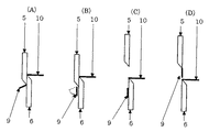
図4は断裁完了後の前端余白断裁片9の挙動を示している。図4(A)は断裁完了直前の前端余白断裁片9がその断裁面を断裁機上刃5の刃先に静電気引力によって吸引され、未断裁部分の僅かな保持力によって垂れ下がることなく斜めに保持されている状態を示している。図4(B)は、断裁が完了した結果未断裁部分の保持力が失われ、前端余白断裁片9がその断裁面と断裁機上刃5との線状の静電気引力を軸に垂れ下がってしまっている状態を示す。断裁完了後の断裁機上刃5の上昇によって、前端余白断裁片9が断裁機下刃6に貼り付いて図4(C)の状態となるか、もしくは、断裁機上刃5の刃先に引き上げられて図4(D)の状態となる。 FIG. 4 shows the behavior of the front edge
以上の前端余白断裁片9が断裁完了後に自由落下できないメカニズムの解析により、前端余白断裁片9の自由落下を保障するためには、断裁完了の前に前端余白断裁片9の断裁面と断裁機上刃5の刃先との静電気引力による吸着を弱くする必要がある事が分かった。こうした観点から、枚葉紙・断裁紙10の断裁中に前端余白断裁片9の断裁面を断裁機上刃5から剥ぎ取るためのスクレーパ−、あるいはブラシを備えた余白断裁片の掻き取り装置を断裁機下刃6に装備することとした。 In order to guarantee the free fall of the front edge
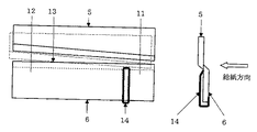
図5は余白断裁片9を断裁機上刃5の刃先から掻き取るための余白断裁片掻き取り装置14を断裁機下刃6に取り付けた状態を示している。余白断裁片掻き取り装置14は断裁機上刃5の刃先に静電気吸着して下降してくる前端余白断裁片9の断裁面に断裁完了前に接触し、断裁機上刃5の更なる下降によって断裁完了以前に前端余白断裁片9の断裁面を掻き剥がす作用をする。この目的から、余白断裁片掻き取り装置14の先端(作用点)は断裁開始位置11と断裁完了位置12との間に位置し、且、断裁完了の前に断裁機上刃5の刃先に静電気吸着している前端余白断裁片9の断裁面に接触する必要があり、図5に示されるように余白断裁片掻き取り装置14は断裁開始位置11から断裁範囲内側の範囲に取り付けられる。 FIG. 5 shows a state in which a blank cutting
図6は余白断裁片掻き取り装置14の機能を示している。図6(A)は断裁機上刃5が停止位置にある状態を示し、余白断裁片掻き取り装置14の先端(作用点)は断裁機下刃6の刃先より下側に位置していることがわかる。図6(B)は断裁機上刃5が下降して断裁完了一歩手前の状態を示し、余白断裁片掻き取り装置14の先端(作用点)が断裁機上刃5に静電気吸引されている前端余白断裁片9の断裁面に接触している。図6(C)は断裁機上刃5がさらに下降した状態を示し、余白断裁片掻き取り装置14の先端(作用点)が断裁機上刃5の刃先によって更に押し下げられ、その先端(作用点)が余白断裁片9とともに断裁機上刃5の刃面をスライドして余白断裁片掻き取り装置14が傾き、断裁面が断裁機下刃6より引き剥がされる。 FIG. 6 shows the function of the margin cutting
この直後に前端余白断裁片9の断裁が完了するが、既に断裁面の一部が断裁機下刃6から引き剥がされ、またその際に前端余白断裁片9に与えられた変形ストレスによって、断裁完了時に前端余白断裁片9がはじき飛ばされることとなり、前端余白断裁片9の断裁機刃物への貼り付きが効果的に防止される。 Immediately after this, the cutting of the front edge
余白断裁片掻き取り装置14の先端(作用点)が断裁機上刃5の刃面をスライドするのは、余白断裁片掻き取り装置14の断裁機下刃6への取り付けに弾性があり、余白断裁片掻き取り装置14が傾くためであり、余白断裁片掻き取り装置14が弾性のある材料で構成されているか、もしくは、スプリング等の弾性体を介して断裁機下刃6に取り付けられているためである。 The leading edge (working point) of the blank cutting
余白断裁片掻き取り装置14の先端(作用点)はスクレーパーの様なヘラで例示されているが、ブラシ、ラバー等の適切な材質とすることができる。 The tip (working point) of the blank cutting
以下、本発明の後端断裁紙片15に対する実施例を、図面を参照して説明する。図7は枚葉紙・断裁紙10を断裁する過程を示している。断面A−Aは未断裁状態を示し、枚葉紙・断裁紙10の後端が断裁機4より後端余白断裁片15の幅に相当する長さだけ残されている。断面B−Bは枚葉紙・断裁紙10の断裁点での状態を示し、枚葉紙・断裁紙10が断裁機上刃5と断裁機下刃6とによって剪断応力を受け、断裁と同時に後端余白断裁片15が上方へ捻じ曲げられている状態となっている。断面C−Cは断裁後の状態を示し、断裁された枚葉紙・断裁紙10の後端が断裁機上刃5によって押し下げられ、また端余白断裁片15は上方に捻じ曲げられと同時に、その断裁面が断裁機下刃6の刃先に押し当てられている。 Hereinafter, an embodiment of the rear edge cut
図8は断裁完了後の後端余白断裁片15の挙動を示している。図8(A)は断裁完了直前の後端余白断裁片15がその断裁面を断裁機上刃5の刃先に静電気引力によって吸引され、未断裁部分の僅かな保持力によって垂れ下がることなく斜めに保持されている状態を示している。図8(B)は、断裁が完了した結果未断裁部分の保持力が失われ、静電気引力によって断裁機下刃6の刃先に吸引されている後端余白断裁片15の断裁面を軸に落下し、断裁機下刃6の傾斜刃面に貼り付いている状態を示す。断裁完了後の断裁機上刃5の上昇によって、図8(C)のごとく後端余白断裁片15がその自重によって自由落下するか、もしくは、図8(D)のごとく断裁機下刃6の傾斜刃面に安定して貼り付いて残留している状態となる。 FIG. 8 shows the behavior of the trailing edge blank cut
図9は実施例1にて提案された余白断裁片掻き取り装置14を後端余白断裁片15の掻き落としに応用するための取付方法を示している。断裁機下刃6の刃先に静電気吸引されている後端断裁片15の断裁面を断裁機下刃6の刃先から掻き剥がすため余白断裁片掻き取り装置14が断裁機下刃6ではなく断裁機上刃5の断裁開始点11から断裁範囲内側の範囲に取り付けられている。 FIG. 9 shows an attachment method for applying the blank cutting
図10は断裁機上刃5に余白断裁片掻き取り装置14を装着した状態での後端余白断裁片15の断裁過程を示している。図10(A)は断裁開始前の状態である。図10(B)は断裁が進行し、断裁機上刃5に取り付けられた余白断裁片掻き取り装置14の先端(作用点)が断裁機下刃6の刃先に静電気吸引されている後端余白断裁片15の断裁面に接触している状態を示している。図10(C)は断裁機上刃5が更に下降し、断裁完了一歩手前の状態を示し、余白断裁片掻き取り装置14はその先端(作用点)が既に断裁機下刃6の刃面に乗っているため、先端を下降させることができず、余白断裁片掻き取り装置14が傾きながらその先端(作用点)を断裁機下刃6の傾斜刃面上にスライドさせ、同時に後端余白断裁片15を断裁機下刃6の刃先から引き剥がし、刃面上に位置させる。 FIG. 10 shows a cutting process of the trailing edge
断裁完了直前の後端余白断裁片15は余白断裁片掻き取り装置14の先端位置では断裁機下刃6の傾斜刃面に乗っており、一方、断裁点では断裁の剪断応力によって上向きに捻じ曲げられているため後端余白断裁片15には捩じり応力の変形ストレスが発生している。このため、断裁完了時のストレスの開放により後端余白断裁片15がはじき飛ばされて断裁機下刃6の傾斜刃面から自由落下することが期待できる。しかし、断裁完了時に後端余白断裁片15は自由落下可能な空間上では無く、断裁機下刃6の傾斜刃面上に位置するため、最終的に傾斜刃面上に残留することを完全に阻止することには疑問残る。 The trailing edge
実施例2では断裁機下刃6の傾斜刃面に断裁を完了した後端余白断裁片15が落下すること無く残留する恐れのあることが懸念された。そこで実施例3では断裁を完了した後端余白断裁片15が断裁機下刃6の傾斜刃面に平面で密着して安定的に残留することのないように図11に示される断裁機下刃刃面突起物16を設けた。断裁機下刃刃面突起物16は余白断裁片掻き取り装置14と断裁終了位置12の間に位置し、後端余白断裁片15の断裁機下刃刃面との平面接触を阻止し、後端余白断裁片15を通紙平面付近に保持する機能を示す。 In Example 2, there was a concern that the trailing edge blank cut
図12で示される如く後端余白断裁片15は余白断裁片掻き取り装置14の位置で断裁機下刃刃面方向へ押し下げられ、断裁機下刃刃面突起物16の位置で断裁機下刃刃先の水平面付近へ持ち上げられ、更に、断裁点では断裁中の剪断応力によって上向きに捻じ曲げられた状態となる。結果的に、後端余白断裁片15は断裁完了直前には断裁面の刃先との静電気吸着を余白断裁片掻き取り装置14によって阻害され、かつ、捻じれと曲げの変形ストレスをかけられた状態となっており、断裁完了によって未断裁部による拘束が解除されると、後端余白断裁片15ははじけ飛び、しかも断裁機下刃6の傾斜刃面に面接触できないため、自由落下をすることとなる。 As shown in FIG. 12, the trailing edge
1. 枚葉紙
2. 断裁機上流側ローラー対
3. 断裁機下流側ローラー対
4. 断裁機
5. 断裁機上刃(可動刃)
6. 断裁機下刃(固定刃)
7. 用紙先端繰り出し長さ
8. 下流側ローラー対/断裁機間距離
9. 前端余白断裁片
10.枚葉紙・断裁紙
11.断裁開始位置
12.断裁完了位置
13.断裁点
14.余白断裁片掻き取り装置
15.後端余白断裁片
16.断裁機下刃刃面突起物1. Sheet of
6). Cutting blade lower blade (fixed blade)
7). 7. Paper
Claims (3)
Priority Applications (1)
| Application Number | Priority Date | Filing Date | Title |
|---|---|---|---|
| JP2016039390A JP6620987B2 (en) | 2016-02-15 | 2016-02-15 | Sheet-fed paper conveyance cutting device with mechanism to prevent sticking of blank cutting pieces to cutting machine blades |
Applications Claiming Priority (1)
| Application Number | Priority Date | Filing Date | Title |
|---|---|---|---|
| JP2016039390A JP6620987B2 (en) | 2016-02-15 | 2016-02-15 | Sheet-fed paper conveyance cutting device with mechanism to prevent sticking of blank cutting pieces to cutting machine blades |
Publications (2)
| Publication Number | Publication Date |
|---|---|
| JP2017144544A true JP2017144544A (en) | 2017-08-24 |
| JP6620987B2 JP6620987B2 (en) | 2019-12-18 |
Family
ID=59681050
Family Applications (1)
| Application Number | Title | Priority Date | Filing Date |
|---|---|---|---|
| JP2016039390A Active JP6620987B2 (en) | 2016-02-15 | 2016-02-15 | Sheet-fed paper conveyance cutting device with mechanism to prevent sticking of blank cutting pieces to cutting machine blades |
Country Status (1)
| Country | Link |
|---|---|
| JP (1) | JP6620987B2 (en) |
Cited By (5)
| Publication number | Priority date | Publication date | Assignee | Title |
|---|---|---|---|---|
| CN108818683A (en) * | 2018-07-18 | 2018-11-16 | 重庆恒宏卫生用品有限公司 | Roll paper production equipment |
| JP2020059110A (en) * | 2018-10-12 | 2020-04-16 | 富士通コンポーネント株式会社 | Cutter and printer |
| US10814509B2 (en) * | 2017-07-20 | 2020-10-27 | Brother Kogyo Kabushiki Kaisha | Cutting apparatus and printer |
| JP7388076B2 (en) | 2019-09-18 | 2023-11-29 | コニカミノルタ株式会社 | Post-processing equipment and image forming system |
| CN108818683B (en) * | 2018-07-18 | 2024-04-30 | 邹平县弘毅纸业有限公司 | Roll paper production equipment |
Citations (9)
| Publication number | Priority date | Publication date | Assignee | Title |
|---|---|---|---|---|
| JPS6261498U (en) * | 1985-10-08 | 1987-04-16 | ||
| JPS62134698U (en) * | 1986-02-14 | 1987-08-25 | ||
| US5377569A (en) * | 1993-05-07 | 1995-01-03 | Xerox Corporation | Signature booklet maker with a modified fold blade and a trim waste elimination device |
| JP2005342854A (en) * | 2004-06-04 | 2005-12-15 | Duplo Corp | Cutting device |
| JP2006205309A (en) * | 2005-01-28 | 2006-08-10 | Duplo Seiko Corp | Cutter |
| JP2007044837A (en) * | 2005-08-11 | 2007-02-22 | Duplo Seiko Corp | Cutting device |
| JP2009269157A (en) * | 2008-05-12 | 2009-11-19 | Duplo Corp | Cutting device |
| JP2010240820A (en) * | 2009-04-07 | 2010-10-28 | Gansaa Japan Kk | Paper sheet conveying and cutting apparatus with discharging mechanism and blushing-off mechanism for cut piece of paper margin |
| JP2012101347A (en) * | 2010-10-14 | 2012-05-31 | Canon Inc | Sheet processing apparatus and image forming apparatus |
-
2016
- 2016-02-15 JP JP2016039390A patent/JP6620987B2/en active Active
Patent Citations (9)
| Publication number | Priority date | Publication date | Assignee | Title |
|---|---|---|---|---|
| JPS6261498U (en) * | 1985-10-08 | 1987-04-16 | ||
| JPS62134698U (en) * | 1986-02-14 | 1987-08-25 | ||
| US5377569A (en) * | 1993-05-07 | 1995-01-03 | Xerox Corporation | Signature booklet maker with a modified fold blade and a trim waste elimination device |
| JP2005342854A (en) * | 2004-06-04 | 2005-12-15 | Duplo Corp | Cutting device |
| JP2006205309A (en) * | 2005-01-28 | 2006-08-10 | Duplo Seiko Corp | Cutter |
| JP2007044837A (en) * | 2005-08-11 | 2007-02-22 | Duplo Seiko Corp | Cutting device |
| JP2009269157A (en) * | 2008-05-12 | 2009-11-19 | Duplo Corp | Cutting device |
| JP2010240820A (en) * | 2009-04-07 | 2010-10-28 | Gansaa Japan Kk | Paper sheet conveying and cutting apparatus with discharging mechanism and blushing-off mechanism for cut piece of paper margin |
| JP2012101347A (en) * | 2010-10-14 | 2012-05-31 | Canon Inc | Sheet processing apparatus and image forming apparatus |
Cited By (5)
| Publication number | Priority date | Publication date | Assignee | Title |
|---|---|---|---|---|
| US10814509B2 (en) * | 2017-07-20 | 2020-10-27 | Brother Kogyo Kabushiki Kaisha | Cutting apparatus and printer |
| CN108818683A (en) * | 2018-07-18 | 2018-11-16 | 重庆恒宏卫生用品有限公司 | Roll paper production equipment |
| CN108818683B (en) * | 2018-07-18 | 2024-04-30 | 邹平县弘毅纸业有限公司 | Roll paper production equipment |
| JP2020059110A (en) * | 2018-10-12 | 2020-04-16 | 富士通コンポーネント株式会社 | Cutter and printer |
| JP7388076B2 (en) | 2019-09-18 | 2023-11-29 | コニカミノルタ株式会社 | Post-processing equipment and image forming system |
Also Published As
| Publication number | Publication date |
|---|---|
| JP6620987B2 (en) | 2019-12-18 |
Similar Documents
| Publication | Publication Date | Title |
|---|---|---|
| JP6620987B2 (en) | Sheet-fed paper conveyance cutting device with mechanism to prevent sticking of blank cutting pieces to cutting machine blades | |
| JP2010240820A (en) | Paper sheet conveying and cutting apparatus with discharging mechanism and blushing-off mechanism for cut piece of paper margin | |
| JP5720915B2 (en) | Glass plate cutting method and glass plate manufacturing method | |
| US20080271869A1 (en) | Tissue paper winding and cutting apparatus | |
| US6966245B1 (en) | Trim edge stripper for a corrugated board rotary cutting die | |
| GB2536562A (en) | Tape applicator | |
| JPS6076997A (en) | Sheet puncher | |
| US4422358A (en) | Apparatus for cutting a continuous narrow strip into short sections | |
| JP2011098419A (en) | Sheet material cutting device and printer using the same | |
| JP4890210B2 (en) | Doctor device doctor blade mounting method, blade insertion groove cleaning method, and cleaning blade | |
| CN114302865A (en) | Method for producing sheet glass and apparatus for producing sheet glass | |
| US20130247732A1 (en) | Rotary cutter device | |
| JP2005342854A (en) | Cutting device | |
| JPH1148187A (en) | Method and device for forming intermittent cut line | |
| US2805857A (en) | Tipping mechanism for filter tip assembling machines and the like | |
| JP5381319B2 (en) | Die cutting machine | |
| JP2016531766A (en) | Filter device | |
| DE102008012885B3 (en) | Bread retaining device for bread cutter, has retaining element including two regions that are fixedly formed in feeding direction of bread at end of discharge channel, where retaining element is designed as belt | |
| CN108515779A (en) | A kind of label machine cutter using dise knife | |
| JP4032090B2 (en) | Mold structure of strip device for automatic punching machine | |
| US1032069A (en) | Scrapper for dough-cutting machines. | |
| CN218126696U (en) | Improved pair-roller type poultry gizzard oiling assembly | |
| JP2006130762A (en) | Dust removing and cutting mechanism in printer apparatus, and method for controlling it | |
| JP6960678B2 (en) | Sheet cutting device | |
| US2550025A (en) | Fish-filleting machine |
Legal Events
| Date | Code | Title | Description |
|---|---|---|---|
| A621 | Written request for application examination |
Free format text: JAPANESE INTERMEDIATE CODE: A621 Effective date: 20181212 |
|
| TRDD | Decision of grant or rejection written | ||
| A977 | Report on retrieval |
Free format text: JAPANESE INTERMEDIATE CODE: A971007 Effective date: 20191016 |
|
| A01 | Written decision to grant a patent or to grant a registration (utility model) |
Free format text: JAPANESE INTERMEDIATE CODE: A01 Effective date: 20191029 |
|
| A61 | First payment of annual fees (during grant procedure) |
Free format text: JAPANESE INTERMEDIATE CODE: A61 Effective date: 20191107 |
|
| R150 | Certificate of patent or registration of utility model |
Ref document number: 6620987 Country of ref document: JP Free format text: JAPANESE INTERMEDIATE CODE: R150 |