JP2017144103A - Electric device, electronic circuit board provided in electric device, and replacement method of electronic circuit board - Google Patents
Electric device, electronic circuit board provided in electric device, and replacement method of electronic circuit board Download PDFInfo
- Publication number
- JP2017144103A JP2017144103A JP2016029104A JP2016029104A JP2017144103A JP 2017144103 A JP2017144103 A JP 2017144103A JP 2016029104 A JP2016029104 A JP 2016029104A JP 2016029104 A JP2016029104 A JP 2016029104A JP 2017144103 A JP2017144103 A JP 2017144103A
- Authority
- JP
- Japan
- Prior art keywords
- control unit
- storage unit
- substrate
- unit
- board
- Prior art date
- Legal status (The legal status is an assumption and is not a legal conclusion. Google has not performed a legal analysis and makes no representation as to the accuracy of the status listed.)
- Pending
Links
Images


Landscapes
- Washing And Drying Of Tableware (AREA)
- Control Of Washing Machine And Dryer (AREA)
Abstract
Description
本発明は、食器洗浄機及び洗濯機などの保守作業を支援する制御部及び記憶部を備えた電気機器、その電気機器が備える電子回路基板、及び電子回路基板の交換方法に関するものである。 The present invention relates to an electric device provided with a control unit and a storage unit for supporting maintenance work such as a dishwasher and a washing machine, an electronic circuit board provided in the electric device, and an electronic circuit board replacement method.
食器洗浄機などの消費生活用製品安全法で点検の制度が設けられている電気機器では、電気機器を安全に使うための目安となる設計標準使用期間が設定されている。そして、この設定標準使用期間を経過したか否かについては、電気機器の待機時間及び運転時間などの設置してからの経過時間をEEPROM(Electrically Erasable Programmable Read−Only Memory)等の記憶部に記憶して管理を行っている(例えば特許文献1参照)。 For electrical appliances that have a system for inspection in accordance with the Consumer Product Safety Law, such as dishwashers, a design standard usage period has been set as a guideline for safe use of electrical appliances. Whether the set standard use period has elapsed or not is stored in a storage unit such as an EEPROM (Electrically Erasable Programmable Read-Only Memory) such as a standby time and an operating time of the electric device. (See, for example, Patent Document 1).
特許文献1に記載の電気機器においては、電気機器の保守作業時に制御部を搭載した基板を交換したい場合には、基板に搭載されているEEPROM等の記憶部を一緒に交換することになる。このため、電気機器の保守作業後において、記憶部に記憶されている情報が作業終了後の電気機器に移行できないという問題点があった。 In the electrical device described in Patent Document 1, when it is desired to replace the substrate on which the control unit is mounted during maintenance of the electrical device, the storage unit such as an EEPROM mounted on the substrate is replaced together. For this reason, after the maintenance work of the electric equipment, there is a problem that the information stored in the storage unit cannot be transferred to the electric equipment after the work.
本発明は、上記のような問題点を解決するためになされたものであり、電気機器の保守作業時においても、記憶部に記憶されている機器情報を保守作業が終了した電気機器に移行できる電気機器を提供することを目的としている。 The present invention has been made to solve the above-described problems, and the apparatus information stored in the storage unit can be transferred to the electric apparatus for which the maintenance work has been completed even during the maintenance work of the electric apparatus. The purpose is to provide electrical equipment.
本発明に係る電気機器は、機器を構成する電気部品のうち少なくとも一つを制御する制御部を有する制御部基板と、前記制御部に接続され機器情報を記憶する記憶部を有する記憶部基板と、前記制御部に接続され報知を行う報知部と、を備えた電気機器であって、前記制御部は、前記機器情報を前記記憶部に記憶させると共に前記機器情報が基準の条件を満たした時に前記報知部を介して保守点検の時期を報知し、前記制御部基板と前記記憶部基板とは、分割部を介して接続されており、かつ前記分割部で分離可能である。 An electrical device according to the present invention includes a control unit substrate having a control unit that controls at least one of electrical components constituting the device, and a storage unit substrate that is connected to the control unit and has a storage unit that stores device information. A notification unit connected to the control unit for performing notification, wherein the control unit stores the device information in the storage unit and the device information satisfies a reference condition. The time of maintenance / inspection is notified via the notification unit, and the control unit substrate and the storage unit substrate are connected via the division unit and can be separated by the division unit.
本発明に係る電気機器によれば、制御部を有する制御部基板と、制御部に接続され機器情報を記憶する記憶部を有する記憶部基板とは、分割部を介して接続されており、かつ分割部を介して分離可能である。このため、電気機器の保守作業時においても、記憶部に記憶されている機器情報を保守作業が終了した電気機器に移行できる電気機器を提供することができる。 According to the electrical device according to the present invention, the control unit substrate having the control unit and the storage unit substrate connected to the control unit and storing the device information are connected via the dividing unit, and Separation is possible via the dividing part. For this reason, it is possible to provide an electrical device that can transfer the device information stored in the storage unit to the electrical device for which the maintenance operation has been completed even during the maintenance operation of the electrical device.
以下、本発明の電気機器の実施の形態について、図面を参照して説明する。なお、図面の形態は一例であり、本発明を限定するものではない。また、各図において同一の符号を付したものは、同一の又はこれに相当するものであり、これは明細書の全文において共通している。さらに、以下の図面では各構成部材の大きさの関係が実際のものとは異なる場合がある。また、本発明における電気機器の例として、食器洗浄機を用いて実施の形態を説明するが、本発明は、食器洗浄機に限定されるものではなく、その他の電気機器にも適用することが可能である。 Hereinafter, embodiments of an electric apparatus according to the present invention will be described with reference to the drawings. In addition, the form of drawing is an example and does not limit this invention. Moreover, what attached | subjected the same code | symbol in each figure is the same or it corresponds, and this is common in the whole text of a specification. Furthermore, in the following drawings, the relationship between the sizes of the constituent members may be different from the actual one. Moreover, although an embodiment will be described using a dishwasher as an example of an electrical device in the present invention, the present invention is not limited to a dishwasher, and may be applied to other electrical devices. Is possible.
実施の形態1.
[食器洗浄機の構成]
図1は、本発明の実施の形態1に係る電気機器の概略断面図である。また、図2は、本発明の実施の形態1に係る電気機器の概略正面図である。図1及び図2に示されるように、食器洗浄機1は、前面に前面開口部1aを有する箱状に形成された食器洗浄機本体1bと、食器洗浄機本体1bの内部に収納され、上方に食器収納口2aを有する箱状に形成された洗浄槽2と、引き出し式の扉13を備えている。
Embodiment 1 FIG.
[Configuration of dishwasher]
FIG. 1 is a schematic cross-sectional view of an electrical apparatus according to Embodiment 1 of the present invention. FIG. 2 is a schematic front view of the electrical apparatus according to Embodiment 1 of the present invention. As shown in FIGS. 1 and 2, the dishwasher 1 is housed in a dishwasher body 1b formed in a box shape having a front opening 1a on the front surface, and the dishwasher body 1b. In addition, a
また、食器洗浄機1の内部には、食器洗浄機本体1bに対し、洗浄槽2を前後方向にスライド移動可能に支持するスライド手段であるガイド(図示省略)とレール5と、食器洗浄機本体1b内に収納された洗浄槽2が設けられている。さらに、食器洗浄機1の内部には、扉13の開閉状態を検出するドア開閉検知装置26と、食器3などの被洗浄物を載置する食器かご4とが設けられている。加えて、食器洗浄機1の内部には、噴射される洗浄水及び乾燥風が、洗浄槽2の外部に流出するのを防止するために、洗浄槽2の食器収納口2aを閉塞するための内蓋12が設けられている。
Further, inside the dishwasher 1, a guide (not shown) that is a sliding means for supporting the
また、食器洗浄機1の内部には、洗浄水となる水道水を洗浄槽2の内部に供給するための給水手段である給水管10a及び給水弁10と、食器3の汚れを洗い落とすために洗浄水を噴射及び循環させるための洗浄手段である洗浄ノズル9及び洗浄ポンプ8とが設けられている。また、食器洗浄機1の内部には、洗浄能力を向上させるために循環する洗浄水を加熱するヒーター7と、洗浄に使用された洗浄水を食器洗浄機1の外部に排水する排水ポンプ11及び配水管11aとが設けられている。
Further, the dishwasher 1 has a water supply pipe 10a and a
また、食器洗浄機1の内部には、食器3を乾燥させるための乾燥風を発生させる送風ファン36と、操作部15からの信号に従い、各種電気部品を制御するための制御部21と、記憶部23とが設けられている。
Further, inside the dishwasher 1, a
図1及び図2に示されるように、送風ファン36は、食器洗浄機本体1bの後方側で洗浄槽2の外側に設けられ、食器3を乾燥させるための空気を送風させるようになっており、乾燥による排気は扉13に形成されている排気口51を経て外部に放出される。
As shown in FIGS. 1 and 2, the
次に、食器洗浄機本体1bの前方側上部には、洗浄槽2が収納されている状態を検出するためのドア開閉検知装置26が設けられている。また、食器洗浄機本体1bの前方側下部には、洗浄槽2の内部の洗浄水の位置を検出するための水量検出装置27が設けられている。さらに、食器洗浄機本体1bの下部には、洗浄水の温度を検出する温度検出装置31が設けられている。
Next, a door open /
図2に示されるように、扉13は、操作パネル14を備え、操作パネル14には、排気口51と、食器洗浄機1を操作するための操作部15と、食器洗浄機1の運転状態等を表示する表示部30と、食器洗浄機1の運転状態等を報知する報知装置41とが設けられている。報知装置41は、例えばブザーなどが用いられる。操作部15には、食器洗浄機1への電源のON又はOFFにするための電源スイッチ18と、食器洗浄機1の運転をスタート又は一時停止させるための運転スイッチ17と、扉13を開閉させるための扉開閉スイッチ20とが設けられている。
As shown in FIG. 2, the
図3は、本発明の実施の形態1に係る電気機器の制御部に係るブロック図である。図3に示されるように、制御部21はマイクロコンピュータ22を備える。制御部21は、ユーザーから操作部15を介して食器洗浄機1への操作指示を受け付けたり、ドア開閉検知装置26等の装置から各種電気信号を受信する。そして、制御部21は、ユーザーからの操作指示又は各種装置等からの電気信号に応じて、マイクロコンピュータ22を介して食器洗浄機1の動作を制御する。すなわち、制御部21は、機器を構成する電気部品のうち少なくとも一つを制御するものである。
FIG. 3 is a block diagram relating to the control unit of the electrical apparatus according to Embodiment 1 of the present invention. As shown in FIG. 3, the
ヒーター駆動回路28は、マイクロコンピュータ22からの制御指令を受けてヒーター7の温度を制御する。給水弁駆動回路32は、マイクロコンピュータ22からの制御指令を受けて給水弁10の開閉等の動作を制御する。洗浄ポンプ駆動回路33は、マイクロコンピュータ22からの制御指令を受けて洗浄ポンプ8の動作を制御する。排水ポンプ駆動回路34は、マイクロコンピュータ22からの制御指令を受けて排水ポンプ11の動作を制御する。送風ファン駆動回路35は、マイクロコンピュータ22からの制御指令を受けて送風ファン36の回転数を制御する。表示部駆動回路29は、マイクロコンピュータ22からの制御指令を受けて表示部30に表示される表示画を制御する。
The
制御部21は、後述する電気配線43又はプリント配線42等により記憶部23に接続されており、記憶部23に食器洗浄機1の積算通電時間、積算運転回数、又は積算運転時間などの機器情報を記憶させる。また、制御部21は、例えば、食器洗浄機1の積算運転時間が一定の積算時間を超えた場合には、報知装置41又は表示部30により保守点検を行う設計標準使用期間が経過したことを報知する。そして、ユーザーは、当該報知があった旨をメーカー等の保守点検業者に連絡することで、適切なタイミングで食器洗浄機1の保守点検、あるいは修理作業等の依頼を行うことができる。
なお、報知装置41及び表示部30は、本発明における「報知部」に相当する。
The
The
図4は、本発明の実施の形態1に係る電気機器に搭載されている基板の概略斜視図である。図4に示されるように、電子回路基板100は、制御部基板40と記憶部基板24とにより構成され、制御部基板40と記憶部基板24とは分割部70により接続されている。制御部基板40には、制御部21とマイクロコンピュータ22とが配設され、記憶部基板24には、記憶部23が配設されている。
つまり、制御部基板40と記憶部基板24は、一枚の板で一体に形成されており、両基板は分割部70の位置で分割することが可能となっている。尚、制御部基板40と記憶部基板24をそれぞれ別々の板で基板を構成し、分割部70となる部分で結合しても良い。
FIG. 4 is a schematic perspective view of a substrate mounted on the electric apparatus according to Embodiment 1 of the present invention. As shown in FIG. 4, the
That is, the
図5は、本発明の実施の形態1に係る電気機器に搭載されている基板の分割部を平面視した概略拡大図である。図5に示されるように、制御部基板40と記憶部基板24との間の分割部70には、複数の貫通孔71aとスリット71bとが形成され、これによりミシン目形状70aが形成されている。貫通孔71aは、例えば直径が1(mm)の貫通孔である。また、貫通孔71a同士の間、及び貫通孔71aとスリット71bとの間、つまり制御部基板40と記憶部基板24との繋ぎ目の幅は、例えば2.5(mm)である。制御部基板40と記憶部基板24とを分割する際には、制御部基板40と記憶部基板24との繋ぎ目を折ったり、切断することで分割して分離することができる。なお、本実施の形態1において、ミシン目形状70aの寸法を上記の通りとしたが、本発明はこれに限定されず、適宜寸法を変更しても良い。
FIG. 5 is a schematic enlarged view of a divided portion of the substrate mounted on the electric device according to Embodiment 1 of the present invention when viewed in plan. As shown in FIG. 5, a plurality of through
図6は、本発明の実施の形態1に係る電気機器に搭載されている基板の分割部を断面視した概略拡大図である。図6に示されるように、制御部基板40と記憶部基板24との間の分割部70には、V字状の溝70bが制御部基板40と記憶部基板24の表面と裏面の両方に形成されている。制御部基板40と記憶部基板24の厚さを例えば1.6(mm)にした場合、V字状の溝70bは、例えば深さを0.4±0.1(mm)とし、角度は45°とする。制御部基板40と記憶部基板24とを分割する際には、制御部基板40と記憶部基板24との間のV字状の溝70bを折ったり、切断することで分割して分離することができる。なお、本実施の形態1において、制御部基板40と記憶部基板24の厚さ及びV字状の溝70bの寸法を上記の通りとしたが、本発明はこれに限定されず、適宜寸法を変更しても良い。
FIG. 6 is a schematic enlarged view of a divided portion of the substrate mounted on the electric device according to Embodiment 1 of the present invention, as viewed in cross section. As shown in FIG. 6, a V-shaped
[実施の形態1の効果]
以上のことから、本実施の形態1によれば、機器を構成する電気部品のうち少なくとも一つを制御する制御部21を有する制御部基板40と、制御部21に接続され機器情報を記憶する記憶部23を有する記憶部基板24と、制御部21に接続され報知を行う報知部と、を備えた電気機器であって、制御部21は、機器情報を記憶部23に記憶させると共に機器情報が基準の条件を満たした時に報知部を介して保守点検の時期を報知し、制御部基板40と記憶部基板24とは、分割部を介して接続されており、かつ分割部で分離可能であるものとする。
このようにすることで、電気機器の保守作業時において、制御部21を交換する場合であっても、記憶部23が設けられた記憶部基板24を、交換する制御部21から切り離し、交換後の新たな制御部21に接続することで、記憶部23に記憶されている情報を保守作業が終了した電気機器に移行できる電気機器を提供することができる。
また、電子回路基板100を製造する際に制御部基板40に記憶部23を組み付けて製造する必要がなくなるため、電子回路基板100の製造時間の削減を図ることができる。
また、記憶部基板24を制御部基板40と隣接して配置して記憶部23が配設された記憶部基板24を目立たせることによって、保守作業時に記憶部23の取り外しを忘れることを防止することができる。
[Effect of Embodiment 1]
From the above, according to the first embodiment, the
In this way, even when the
In addition, when the
Further, by disposing the
また、分割部70は、ミシン目形状70a、又はV字状の溝70bにより形成されている。このようにすることで、分割部70を折り曲げたり切断することで、容易に記憶部基板24と制御部基板40とを分割することができる電気機器を得ることができる。
The dividing
実施の形態2.
本実施の形態2における電気機器の基本的な構成は実施の形態1における電気機器と同様であるため、以下、実施の形態1との相違点を中心に本実施の形態2を説明する。実施の形態1と本実施の形態2との相違点は、各基板にコネクタが設けられている点である。
Since the basic configuration of the electric device according to the second embodiment is the same as that of the electric device according to the first embodiment, the second embodiment will be described below with a focus on differences from the first embodiment. The difference between the first embodiment and the second embodiment is that a connector is provided on each board.
図7Aは、本発明の実施の形態2に係る電気機器に搭載されている基板の概略斜視図である。また、図7Bは、本発明の実施の形態2に係る電気機器に搭載されている基板の底面図である。また、図7Cは、本発明の実施の形態2に係る電気機器に搭載されている基板が分割された際の概略斜視図である。
FIG. 7A is a schematic perspective view of a substrate mounted on an electric device according to
図7Aに示されるように、電子回路基板101は、制御部基板40aと記憶部基板24aとから構成され、制御部基板40aは制御部側コネクタ25aを備え、記憶部基板24aは記憶部側コネクタ25bを備えている。図7Bに示されるように、制御部基板40aと記憶部基板24aとが分割部70を介して接続されている場合は、制御部21と記憶部23とがプリント配線42により電気的に接続され機器情報が記憶部23に記憶されている。しかし、図7Cに示されるように、制御部基板40aと記憶部基板24aとが分割部70において分割された場合、制御部基板40aの制御部側コネクタ25aと記憶部基板24aの記憶部側コネクタ25bとを接続することにより、記憶部23と制御部21との間で機器情報の送受信が行える。
As shown in FIG. 7A, the
次に、電子回路基板101の交換方法について説明する。まず、第1の工程として制御部基板40aと記憶部基板24aとを分割部70で分割する。次に、第2の工程として分離した記憶部基板24aの記憶部側コネクタ25bを、新たな制御部21を有する新たな制御部基板40aに備えられた制御部側コネクタ25aに接続し、分離した記憶部基板24aの記憶部23と、新たな制御部基板40aが有する新たな制御部21と接続する。このようにすることで、記憶部23に記憶されている機器情報を新たな制御部21に移行することができる。
Next, a method for replacing the
[実施の形態2の効果]
以上のことから、本実施の形態2によれば、制御部基板40aは、制御部側コネクタを更に有し、記憶部基板24aは、制御部側コネクタ25aと接続可能な記憶部側コネクタ25bを更に有し、制御部基板40aと記憶部基板24aとが分割部70を介して接続されている状態では、記憶部23は、プリント配線を介して制御部21と接続され、制御部側コネクタ25aと記憶部側コネクタ25bとは接続されていない電気機器とする。
このようにすることで、制御部基板40aと記憶部基板24aとを分割した後においても、記憶部基板24aを再度、交換後の新たな制御部基板40aに接続することができる電気機器を得ることができる。
[Effect of Embodiment 2]
From the above, according to the second embodiment, the
In this way, even after the
実施の形態3.
本実施の形態3における電気機器の基本的な構成は実施の形態1における電気機器と同様であるため、以下、実施の形態1との相違点を中心に本実施の形態3を説明する。実施の形態1と本実施の形態3との相違点は、各基板にコネクタが設けられ、コネクタ同士が電気配線で接続されている点である。
Embodiment 3 FIG.
Since the basic configuration of the electric device according to the third embodiment is the same as that of the electric device according to the first embodiment, the third embodiment will be described below with a focus on differences from the first embodiment. The difference between the first embodiment and the third embodiment is that a connector is provided on each substrate and the connectors are connected to each other by electric wiring.
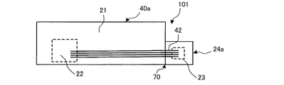
図8は、本発明の実施の形態3に係る電気機器に搭載されている基板の概略斜視図である。図8に示されるように、電子回路基板102は、制御部基板40bと記憶部基板24bとから構成され、制御部基板40bはコネクタ25cを備え、記憶部基板24bはコネクタ25dを備えている。コネクタ25cとコネクタ25dとはリード線などの電気配線43を介して接続されている。そして、制御部21と記憶部23とが電気配線43により電気的に接続され機器情報が記憶部23に記憶されている。電気配線43はコネクタ25cから取り外されることができるため、制御部基板40bと記憶部基板24bとが分割部70を介して分割された場合には、制御部基板40bと記憶部基板24bとを分離することができる。なお、コネクタ25cは、本発明における「第1の接続部」に相当する。また、コネクタ25dは、本発明における「第2の接続部」に相当する。
FIG. 8 is a schematic perspective view of a substrate mounted on an electrical apparatus according to Embodiment 3 of the present invention. As shown in FIG. 8, the
[実施の形態3の効果]
以上のことから、本実施の形態3によれば、制御部基板40bは、コネクタ25cを更に有し、記憶部基板24bは、コネクタ25dを更に有し、コネクタ25cとコネクタ25dとは、電気配線43により接続されている。
このようにすることで、各基板にプリント配線42を配設する必要がなくなり製造工程を簡素化することが可能な電気機器を得ることができる。
[Effect of Embodiment 3]
As described above, according to the third embodiment, the
By doing in this way, it is not necessary to arrange the printed
実施の形態4.
本実施の形態4における電気機器の基本的な構成は実施の形態1における電気機器と同様であるため、以下、実施の形態1との相違点を中心に本実施の形態4を説明する。実施の形態1と本実施の形態4との相違点は、プリント配線がミシン目状の間に配設されている点である。
Since the basic configuration of the electric device according to the fourth embodiment is the same as that of the electric device according to the first embodiment, the fourth embodiment will be described below with a focus on differences from the first embodiment. The difference between the first embodiment and the fourth embodiment is that the printed wiring is arranged between perforations.
図9Aは、本発明の実施の形態4に係る電気機器に搭載されている基板の概略斜視図である。また、図9Bは、本発明の実施の形態4に係る電気機器に搭載されている基板の分割部を平面視した概略拡大図である。図9Aに示されるように、電子回路基板103は、制御部基板40cと記憶部基板24cとから構成され、制御部基板40cと記憶部基板24cとは、分割部70を介して接続されている。図9Bに示されるように、制御部基板40cと記憶部基板24cとの間の分割部70には、複数の貫通孔71aとスリット71bとが形成され、これによりミシン目形状70aが形成されている。貫通孔71a同士、又は貫通孔71aとスリット71bとの間には、プリント配線42が配設され、制御部21と記憶部23とがプリント配線42により電気的に接続され機器情報が記憶部23に記憶される。なお、貫通孔71a及びスリット71bは、本発明における「ミシン目」に相当する。
FIG. 9A is a schematic perspective view of a substrate mounted on an electric device according to
[実施の形態4の効果]
以上のことから、本実施の形態4によれば、プリント配線42は、分割部70のミシン目形状70aのミシン目の間に配設されている。
このようにすることで、分割部70にミシン目形状70aを採用した場合にも、制御部21と記憶部23とをプリント配線42で電気的に接続することができる。
[Effect of Embodiment 4]
From the above, according to the fourth embodiment, the printed
In this way, even when the
実施の形態5.
本実施の形態5における電気機器の基本的な構成は実施の形態1における電気機器と同様であるため、以下、実施の形態1との相違点を中心に本実施の形態5を説明する。実施の形態1と本実施の形態5との相違点は、基板の一方の面の分割部にV字状の溝70bを設けている点である。
Since the basic configuration of the electric device in the fifth embodiment is the same as that of the electric device in the first embodiment, the fifth embodiment will be described below with a focus on differences from the first embodiment. The difference between the first embodiment and the fifth embodiment is that a V-shaped
図10Aは、本発明の実施の形態5に係る電気機器に搭載されている基板の概略斜視図である。また、図10Bは、本発明の実施の形態5に係る電気機器に搭載されている基板の分割部を断面視した概略拡大図である。図10A及び図10Bに示されるように、電子回路基板104は、制御部基板40dと記憶部基板24dとから構成され、制御部基板40dと記憶部基板24dとは、分割部70を介して接続されている。
FIG. 10A is a schematic perspective view of a substrate mounted on an electric device according to
制御部基板40dと記憶部基板24dとの間の分割部70には、V字状の溝70bが制御部基板40dと記憶部基板24dの一方の面のみに形成されている。制御部基板40dと記憶部基板24dの厚さを例えば1.6(mm)にした場合、V字状の溝70bは、例えば深さを0.4±0.1(mm)とし、角度は45°とする。制御部基板40dと記憶部基板24dとを分割する際には、制御部基板40dと記憶部基板24dとの間のV字状の溝70bを折ったり、切断することで分割して分離することができる。なお、本実施の形態5において、制御部基板40と記憶部基板24の厚さ及びV字状の溝70bの寸法を上記の通りとしたが、本発明はこれに限定されず、適宜寸法を変更しても良い。
A V-shaped
制御部基板40dと記憶部基板24dのV字状の溝70bが形成されていない他方の面にはプリント配線42が配設されている。これにより、制御部21と記憶部23とがプリント配線42により電気的に接続され機器情報が記憶部23に記憶される。
A printed
[実施の形態5の効果]
以上のことから、本実施の形態5によれば、V字状の溝70bは、分割部70の一方の面にのみ形成され、プリント配線42は、分割部70のV字状の溝70bが形成されていない他方の面に配設される構成とする。
このようにすることで、分割部70にV字状の溝70bを形成しても、制御部21と記憶部23とをプリント配線42により電気的に接続することができる。
[Effect of Embodiment 5]
From the above, according to the fifth embodiment, the V-shaped
By doing in this way, even if the V-shaped
1 食器洗浄機、1a 前面開口部、1b 食器洗浄機本体、2 洗浄槽、2a 食器収納口、3 食器、4 食器かご、5 レール、7 ヒーター、8 洗浄ポンプ、9 洗浄ノズル、10 給水弁、10a 給水管、11 排水ポンプ、11a 配水管、12 内蓋、13 扉、14 操作パネル、15 操作部、17 運転スイッチ、18 電源スイッチ、20 扉開閉スイッチ、21 制御部、22 マイクロコンピュータ、23 記憶部、24 記憶部基板、24a 記憶部基板、24b 記憶部基板、24c 記憶部基板、24d 記憶部基板、25a 制御部側コネクタ、25b 記憶部側コネクタ、25c コネクタ、25d コネクタ、26 ドア開閉検知装置、27 水量検出装置、28 ヒーター駆動回路、29 表示部駆動回路、30 表示部、31 温度検出装置、32 給水弁駆動回路、33 洗浄ポンプ駆動回路、34 排水ポンプ駆動回路、35 送風ファン駆動回路、36 送風ファン、40 制御部基板、40a 制御部基板、40b 制御部基板、40c 制御部基板、40d 制御部基板、41 報知装置、42 プリント配線、43 電気配線、51 排気口、70 分割部、70a ミシン目形状、70b V字状の溝部、71a 貫通孔、71b スリット、100 電子回路基板、101 電子回路基板、102 電子回路基板、103 電子回路基板、104 電子回路基板。 DESCRIPTION OF SYMBOLS 1 Tableware washing machine, 1a Front opening part, 1b Tableware washing machine main body, 2 Washing tank, 2a Tableware storage port, 3 Tableware, 4 Tableware basket, 5 Rail, 7 Heater, 8 Washing pump, 9 Washing nozzle, 10 Water supply valve, 10a Water supply pipe, 11 Drain pump, 11a Water distribution pipe, 12 Inner lid, 13 Door, 14 Operation panel, 15 Operation part, 17 Operation switch, 18 Power switch, 20 Door open / close switch, 21 Control part, 22 Microcomputer, 23 Memory Unit, 24 storage unit substrate, 24a storage unit substrate, 24b storage unit substrate, 24c storage unit substrate, 24d storage unit substrate, 25a control unit side connector, 25b storage unit side connector, 25c connector, 25d connector, 26 door open / close detection device 27 Water quantity detection device 28 Heater drive circuit 29 Display unit drive circuit 30 Display unit 31 Temperature detection device, 32 Water supply valve drive circuit, 33 Cleaning pump drive circuit, 34 Drain pump drive circuit, 35 Blower fan drive circuit, 36 Blower fan, 40 Control part board, 40a Control part board, 40b Control part board, 40c Control Sub board, 40d Control board, 41 Notification device, 42 Printed wiring, 43 Electrical wiring, 51 Exhaust port, 70 Dividing part, 70a Perforated shape, 70b V-shaped groove, 71a Through hole, 71b Slit, 100 Electronic circuit Board, 101 electronic circuit board, 102 electronic circuit board, 103 electronic circuit board, 104 electronic circuit board.
Claims (11)
前記制御部に接続され機器情報を記憶する記憶部を有する記憶部基板と、
前記制御部に接続され報知を行う報知部と、を備えた電気機器であって、
前記制御部は、前記機器情報を前記記憶部に記憶させると共に前記機器情報が基準の条件を満たした時に前記報知部を介して保守点検の時期を報知し、
前記制御部基板と前記記憶部基板とは、分割部を介して接続されており、かつ前記分割部で分離可能である
電気機器。 A control unit board having a control unit for controlling at least one of the electrical components constituting the device;
A storage unit substrate connected to the control unit and having a storage unit for storing device information;
An electrical device comprising a notification unit connected to the control unit and performing notification,
The control unit stores the device information in the storage unit and informs the maintenance inspection time via the notification unit when the device information satisfies a standard condition,
The control unit substrate and the storage unit substrate are connected to each other through a dividing unit, and can be separated by the dividing unit.
前記記憶部基板は、前記制御部側コネクタと接続可能な記憶部側コネクタを更に有し、
前記制御部基板と前記記憶部基板とが前記分割部を介して接続されている状態では、
前記記憶部は、プリント配線を介して前記制御部と接続され、
前記制御部側コネクタと前記記憶部側コネクタとは接続されていない
請求項1に記載の電気機器。 The control unit board further includes a control unit side connector,
The storage unit substrate further includes a storage unit side connector connectable to the control unit side connector,
In a state where the control unit substrate and the storage unit substrate are connected via the dividing unit,
The storage unit is connected to the control unit via a printed wiring,
The electrical device according to claim 1, wherein the control unit side connector and the storage unit side connector are not connected.
前記記憶部基板は、第2の接続部を更に有し、
前記第1の接続部と前記第2の接続部とは、電気配線により接続されている
請求項1に記載の電気機器。 The control unit substrate further includes a first connection unit,
The storage unit substrate further includes a second connection unit,
The electric device according to claim 1, wherein the first connection portion and the second connection portion are connected by electric wiring.
ミシン目形状により形成されている
請求項1〜3の何れか1項に記載の電気機器。 The dividing unit is
The electric device according to claim 1, wherein the electric device is formed by a perforation shape.
V字状の溝により形成されている
請求項1〜3の何れか1項に記載の電気機器。 The dividing unit is
The electrical device according to claim 1, wherein the electrical device is formed by a V-shaped groove.
請求項2に従属する請求項4に記載の電気機器。 The electric device according to claim 4, wherein the printed wiring is disposed between perforations having a perforation shape in the divided portion.
前記プリント配線は、前記分割部の前記V字状の溝が形成されていない他方の面に配設されている
請求項2に従属する請求項5に記載の電気機器。 The V-shaped groove is formed only on one surface of the divided portion,
The electric device according to claim 5, wherein the printed wiring is disposed on the other surface of the divided portion where the V-shaped groove is not formed.
前記電気機器の積算通電時間、積算運転回数、又は積算運転時間である
請求項1〜7の何れか1項に記載の電気機器。 The device information is
The electrical device according to any one of claims 1 to 7, which is an accumulated energization time, an accumulated operation count, or an accumulated operation time of the electrical device.
請求項1〜8の何れか1項に記載の電気機器。 The electric device according to claim 1, wherein the electric device is a dishwasher.
前記制御部に接続され情報を記憶する記憶部を有する記憶部基板と、
を備え、
前記制御部基板と前記記憶部基板とは、分割部を介して接続されており、かつ前記分割部で分離可能である
電子回路基板。 A control unit board having a control unit for controlling electrical components;
A storage unit substrate having a storage unit connected to the control unit and storing information;
With
The electronic circuit board, wherein the control unit substrate and the storage unit substrate are connected via a dividing unit and can be separated by the dividing unit.
前記制御部に接続され機器情報を記憶する記憶部と記憶部側コネクタを有する記憶部基板とを備え、前記制御部基板と前記記憶部基板とは分割部を介して接続されている電子回路基板の交換方法であって、
前記制御部基板と前記記憶部基板を前記分割部で分離する工程と、
分離した前記記憶部基板の記憶部側コネクタを新たな制御部を有する新たな制御部基板に備えられた制御部側コネクタに接続し、分離した前記記憶部基板の記憶部と、前記新たな制御部基板が有する前記新たな制御部とを接続する工程と、を有する電子回路基板の交換方法。 A control unit board having a control unit for controlling at least one of the electrical components constituting the device;
An electronic circuit board comprising: a storage unit connected to the control unit for storing device information; and a storage unit substrate having a storage unit side connector, wherein the control unit substrate and the storage unit substrate are connected via a dividing unit. Exchange method,
Separating the control unit substrate and the storage unit substrate by the dividing unit;
The storage unit side connector of the separated storage unit substrate is connected to the control unit side connector provided in the new control unit board having a new control unit, and the storage unit of the separated storage unit substrate and the new control And a step of connecting the new control unit included in the partial substrate.
Priority Applications (1)
| Application Number | Priority Date | Filing Date | Title |
|---|---|---|---|
| JP2016029104A JP2017144103A (en) | 2016-02-18 | 2016-02-18 | Electric device, electronic circuit board provided in electric device, and replacement method of electronic circuit board |
Applications Claiming Priority (1)
| Application Number | Priority Date | Filing Date | Title |
|---|---|---|---|
| JP2016029104A JP2017144103A (en) | 2016-02-18 | 2016-02-18 | Electric device, electronic circuit board provided in electric device, and replacement method of electronic circuit board |
Publications (1)
| Publication Number | Publication Date |
|---|---|
| JP2017144103A true JP2017144103A (en) | 2017-08-24 |
Family
ID=59682493
Family Applications (1)
| Application Number | Title | Priority Date | Filing Date |
|---|---|---|---|
| JP2016029104A Pending JP2017144103A (en) | 2016-02-18 | 2016-02-18 | Electric device, electronic circuit board provided in electric device, and replacement method of electronic circuit board |
Country Status (1)
| Country | Link |
|---|---|
| JP (1) | JP2017144103A (en) |
Citations (9)
| Publication number | Priority date | Publication date | Assignee | Title |
|---|---|---|---|---|
| JPH0292965U (en) * | 1989-01-09 | 1990-07-24 | ||
| JP2003240352A (en) * | 2002-02-12 | 2003-08-27 | Matsushita Electric Ind Co Ltd | Kerosine hot-water heater |
| JP2010131546A (en) * | 2008-12-05 | 2010-06-17 | Panasonic Electric Works Co Ltd | Water treatment apparatus |
| JP2010186957A (en) * | 2009-02-13 | 2010-08-26 | Seiko Instruments Inc | Flexible printed wiring board, module, and method of manufacturing the module |
| JP2010207390A (en) * | 2009-03-10 | 2010-09-24 | Panasonic Corp | Washing machine having constitution for managing operating history |
| WO2011152030A1 (en) * | 2010-06-01 | 2011-12-08 | パナソニック株式会社 | Dishwashing machine |
| JP2012059793A (en) * | 2010-09-07 | 2012-03-22 | Ccs Inc | Led wiring board and light irradiation device |
| JP2013031705A (en) * | 2012-10-25 | 2013-02-14 | Panasonic Corp | Dishwasher |
| JP2013084252A (en) * | 2011-10-12 | 2013-05-09 | Kofukin Seimitsu Kogyo (Shenzhen) Yugenkoshi | Storage device |
-
2016
- 2016-02-18 JP JP2016029104A patent/JP2017144103A/en active Pending
Patent Citations (9)
| Publication number | Priority date | Publication date | Assignee | Title |
|---|---|---|---|---|
| JPH0292965U (en) * | 1989-01-09 | 1990-07-24 | ||
| JP2003240352A (en) * | 2002-02-12 | 2003-08-27 | Matsushita Electric Ind Co Ltd | Kerosine hot-water heater |
| JP2010131546A (en) * | 2008-12-05 | 2010-06-17 | Panasonic Electric Works Co Ltd | Water treatment apparatus |
| JP2010186957A (en) * | 2009-02-13 | 2010-08-26 | Seiko Instruments Inc | Flexible printed wiring board, module, and method of manufacturing the module |
| JP2010207390A (en) * | 2009-03-10 | 2010-09-24 | Panasonic Corp | Washing machine having constitution for managing operating history |
| WO2011152030A1 (en) * | 2010-06-01 | 2011-12-08 | パナソニック株式会社 | Dishwashing machine |
| JP2012059793A (en) * | 2010-09-07 | 2012-03-22 | Ccs Inc | Led wiring board and light irradiation device |
| JP2013084252A (en) * | 2011-10-12 | 2013-05-09 | Kofukin Seimitsu Kogyo (Shenzhen) Yugenkoshi | Storage device |
| JP2013031705A (en) * | 2012-10-25 | 2013-02-14 | Panasonic Corp | Dishwasher |
Similar Documents
| Publication | Publication Date | Title |
|---|---|---|
| CN103565384A (en) | Full intelligent ultrasonic dish-washing machine | |
| JP2017144103A (en) | Electric device, electronic circuit board provided in electric device, and replacement method of electronic circuit board | |
| JP2005143789A (en) | Dishwasher | |
| JP2009297356A (en) | Dish washer | |
| JP4697019B2 (en) | dishwasher | |
| CN111053508A (en) | Control method of washing electric appliance system and washing electric appliance system | |
| JP2006014752A (en) | Fully automatic washing machine | |
| JP2006317039A (en) | Ice making machine | |
| JP2007125165A (en) | Dishwasher | |
| JP6326625B2 (en) | Sanitary washing device | |
| TWI421799B (en) | Tableware cleaning machine | |
| KR100572777B1 (en) | Installation for defense of over flow washing water in vessel washing machine and controlling method thereof | |
| US20180168424A1 (en) | Coupling and decoupling jig for dispenser assembly of dishwasher | |
| JP2015024383A (en) | Washing device and dirt removing method | |
| JP5206742B2 (en) | dishwasher | |
| JP4797765B2 (en) | dishwasher | |
| JP2018126323A (en) | Boiled noodle machine | |
| JP2018117809A (en) | Electrical equipment | |
| JP5212424B2 (en) | dishwasher | |
| JP2009207797A (en) | Dishwasher | |
| CN112353333B (en) | Heat interaction device for dish washing machine and dish washing machine | |
| JP5104779B2 (en) | dishwasher | |
| JP2007282750A (en) | Dishwasher | |
| JP2021037040A (en) | Washing machine system | |
| JP6234357B2 (en) | Dishwasher |
Legal Events
| Date | Code | Title | Description |
|---|---|---|---|
| A621 | Written request for application examination |
Free format text: JAPANESE INTERMEDIATE CODE: A621 Effective date: 20180625 |
|
| A131 | Notification of reasons for refusal |
Free format text: JAPANESE INTERMEDIATE CODE: A131 Effective date: 20190319 |
|
| A977 | Report on retrieval |
Free format text: JAPANESE INTERMEDIATE CODE: A971007 Effective date: 20190322 |
|
| A521 | Request for written amendment filed |
Free format text: JAPANESE INTERMEDIATE CODE: A523 Effective date: 20190515 |
|
| A02 | Decision of refusal |
Free format text: JAPANESE INTERMEDIATE CODE: A02 Effective date: 20191029 |