JP2017143608A - Band clip and wiring harness - Google Patents
Band clip and wiring harness Download PDFInfo
- Publication number
- JP2017143608A JP2017143608A JP2016022027A JP2016022027A JP2017143608A JP 2017143608 A JP2017143608 A JP 2017143608A JP 2016022027 A JP2016022027 A JP 2016022027A JP 2016022027 A JP2016022027 A JP 2016022027A JP 2017143608 A JP2017143608 A JP 2017143608A
- Authority
- JP
- Japan
- Prior art keywords
- band
- clip
- support plate
- shaft
- dimension
- Prior art date
- Legal status (The legal status is an assumption and is not a legal conclusion. Google has not performed a legal analysis and makes no representation as to the accuracy of the status listed.)
- Pending
Links
Images


Abstract
Description
本発明は、自動車に配索するワイヤハーネスを車体パネルの係止孔に防水を図りつつ係止するバンドクリップおよびワイヤハーネスに関する。 The present invention relates to a band clip and a wire harness for locking a wire harness arranged in an automobile while waterproofing to a locking hole of a vehicle body panel.
図6に示すバンドクリップは、特許文献1の図7に示すワイヤハーネス係止用のバンドクリップと実質的の同一のものを示す。 The band clip shown in FIG. 6 is substantially the same as the band clip for locking the wire harness shown in FIG.
このバンドクリップ30は、バンド部32とクリップ部33とからなるバンドクリップ本体31と、弾性防水部材34と、を有している。クリップ部33は、皿部35と軸部36と係止頭部37とを有する。弾性防水部材34は、円環体形状であり、中心孔に係止頭部37が挿通され皿部35に密着して軸部36に嵌合している。
The
このバンドクリップ30は、バンド部32とで電線束Wを一巻きに保持することにより、バンドクリップ30をワイヤハーネスとして組み付けた状態で、車体パネルPの係止孔Hに係止頭部37を挿入して、係止段部37aを係止孔Hの周縁部に係止して固定する一方、皿部35と係止頭部37とで車体パネルPを挟持するとともに、弾性防水部材34が皿部35と車体パネルPとで挟圧され係止孔Hに対し止水するようになっている。
The
しかしながら、上記のワイヤハーネスは、円環体形状の弾性防水部材が、中心孔に係止頭部が挿通され皿部に密着して軸部に嵌合している。このため、中心孔の径が小さいと弾性防水部材を取り付ける作業が難しく、剛性によっては破れてしまうこともある。 However, in the above-described wire harness, the elastic waterproof member having a toroidal shape is fitted into the shaft portion in close contact with the dish portion with the locking head inserted through the center hole. For this reason, when the diameter of the center hole is small, it is difficult to attach the elastic waterproof member, and it may be broken depending on the rigidity.
また、上記のワイヤハーネスは、電線束Wを一巻きに保持したバンドクリップを、皿部と係止頭部とで車体パネルPを挟持するように取り付けたとき、取付角度や電線束Wの重さ等によってバンドクリップ本体が傾くと、追随して弾性防水部材も傾くことがあり、弾性防水部材の一部分が車体パネルから離脱するほどに傾いた際には止水不能になるという問題点があった。 In addition, when the above-described wire harness is attached so that the vehicle body panel P is sandwiched between the plate portion and the locking head, the band clip that holds the wire bundle W in one turn is attached. If the band clip body tilts due to such factors as the elastic waterproofing member, the elastic waterproofing member may also tilt, and if a part of the elastic waterproofing member is tilted so as to be detached from the vehicle body panel, it becomes impossible to stop water. It was.
本発明は、上述した問題に鑑みてなされたもので、弾性防水部材の取り付けが容易で、取付中心からオフセットした位置に電線束を保持する場合にも確実な止水が行えるバンドクリップおよびワイヤハーネスを提供することを目的としている。 The present invention has been made in view of the above-described problems, and is a band clip and a wire harness that can be attached with an elastic waterproof member easily and can reliably stop water even when an electric wire bundle is held at a position offset from the mounting center. The purpose is to provide.
本発明に係るバンドクリップは、上記課題を解決するため、バンド部および前記バンド部のベース部に一体に設けられたクリップ部とからなるバンドクリップ本体と、環状の弾性防水部材と、を有し、前記クリップ部は、車体パネルの係止孔の周縁部に対応するように前記ベース部に一体に設けられた支持板部と、前記支持板部の中央より延在された軸部と、前記軸部の先端より折り返して延在する係止頭部と、を有し、取付時に、前記軸部が車体パネルの係止孔を通る状態になるとともに、前記係止頭部が前記係止孔を通過しかつ前記係止孔の周縁部に係止するように構成され、前記弾性防水部材は、肉厚方向の中間部に形成された前記支持板部の外周部を収容する外周部収容空間と、前記外周部収容空間を上下に貫通し前記軸部を挿通する軸部挿通孔と、前記係止頭部側の面に前記軸部挿通孔の外側を周回するように突出して設けられ、前記取付時、前記車体パネルの前記係止孔の周縁部に密着する止水リップ部と、を有し、前記止水リップ部は、前記バンド部で保持する電線束の負荷が前記軸部に曲げモーメントとして作用し前記軸部が撓み前記支持板部が傾いた場合にも、前記車体パネルとの密着が維持されるようになっている構成である。 In order to solve the above problems, a band clip according to the present invention has a band clip body including a band portion and a clip portion integrally provided on a base portion of the band portion, and an annular elastic waterproof member. The clip portion includes a support plate portion provided integrally with the base portion so as to correspond to a peripheral edge portion of the locking hole of the vehicle body panel, a shaft portion extending from the center of the support plate portion, A locking head that is folded back and extended from the tip of the shaft portion, and when the shaft is attached, the shaft portion passes through the locking hole of the vehicle body panel, and the locking head is the locking hole. And the elastic waterproofing member is configured to be engaged with a peripheral edge of the engaging hole, and the elastic waterproof member is an outer peripheral portion accommodating space for accommodating an outer peripheral portion of the support plate portion formed at an intermediate portion in the thickness direction. And penetrates the outer periphery housing space up and down and through the shaft A shaft portion insertion hole and a surface on the side of the locking head portion are provided so as to protrude around the outside of the shaft portion insertion hole, and in close contact with the peripheral edge portion of the locking hole of the vehicle body panel A water stop lip portion, and the water stop lip portion is a case where the load of the electric wire bundle held by the band portion acts as a bending moment on the shaft portion and the shaft portion is bent and the support plate portion is inclined. In addition, the close contact with the vehicle body panel is maintained.
上記構成により、本発明のバンドクリップは、弾性防水部材の軸部挿通孔を係止頭部を通し易い径とすることで、弾性防水部材の支持板部への取り付けが容易となり、取付時に弾性防水部材を損傷することもない。 With the above configuration, the band clip of the present invention has a diameter that allows the shaft insertion hole of the elastic waterproof member to easily pass through the locking head, thereby facilitating the attachment of the elastic waterproof member to the support plate portion and is elastic when installed. The waterproof member is not damaged.
また、本発明のバンドクリップは、軸部に作用する曲げモーメントにより支持板部が傾いた場合にも、弾性防水部材の止水リップ部が車体パネルとの密着が維持されるため、支持板部が傾いた場合でも確実に止水機能を果たすことができる。 In addition, the band clip of the present invention has the support plate portion because the water stop lip portion of the elastic waterproof member is maintained in close contact with the vehicle body panel even when the support plate portion is inclined due to a bending moment acting on the shaft portion. Even when tilted, it can reliably perform the water stop function.
上記構成のバンドクリップにおいて、前記止水リップ部は、前記車体パネルの前記係止頭部が通り抜けた側の面から前記弾性防水部材の前記係止頭部側の面までの寸法aから前記車体パネルの厚さdを差し引いた寸法fに圧縮寸法eを足した高さ寸法cであって、前記高さ寸法cは、前記支持板部が傾いた場合に前記寸法fよりも大きく変化する寸法f'よりも大きく設定されていてもよい。 In the band clip having the above-described configuration, the water stop lip portion is formed from a dimension a from a surface of the vehicle body panel on the side where the locking head passes through to a surface on the locking head side of the elastic waterproof member. A height dimension c obtained by adding a compression dimension e to a dimension f obtained by subtracting the thickness d of the panel, and the height dimension c changes larger than the dimension f when the support plate portion is inclined. It may be set larger than f ′.
上記構成により、本発明のバンドクリップは、弾性防水部材に上記高さ寸法cの止水リップ部を設けることで、上記寸法f'になるように支持板部13が傾いたときにも、止水リップ部と車体パネルとの密着が維持され、弾性防水部材による止水機能を維持することができる。
With the above configuration, the band clip according to the present invention is provided with the water stop lip portion having the height dimension c on the elastic waterproof member, so that the
本発明に係るワイヤハーネスは、上記課題を解決するため、上記構成のバンドクリップの前記バンド部により電線束または電線束に被さるコルゲートチューブを巻いた状態に保持されてなる構成である。 The wire harness according to the present invention has a configuration in which a wire bundle or a corrugated tube covering the wire bundle is held by the band portion of the band clip having the above configuration in order to solve the above problems.
上記の構成により、本発明に係るワイヤハーネスは、弾性防水部材の支持板部への取り付けが容易となり、支持板部が軸に作用する曲げモーメントにより傾いた場合でも確実に止水機能を果たすことができる。 With the above configuration, the wire harness according to the present invention can be easily attached to the support plate portion of the elastic waterproof member, and can reliably perform a water stop function even when the support plate portion is inclined by a bending moment acting on the shaft. Can do.
本発明によれば、弾性防水部材の取り付けが容易で、取付中心からオフセットした位置に電線束を保持する場合にも確実な止水が行えるバンドクリップおよびワイヤハーネスを提供することができる。 According to the present invention, it is possible to provide a band clip and a wire harness that can be attached with an elastic waterproof member easily and can reliably stop water even when the wire bundle is held at a position offset from the attachment center.
以下、本発明の実施形態に係るバンドクリップおよびワイヤハーネスについて図面を参照して説明する。 Hereinafter, a band clip and a wire harness according to an embodiment of the present invention will be described with reference to the drawings.
図1〜図4は、本発明の実施形態に係るバンドクリップおよびワイヤハーネスを示す。ワイヤハーネス1は、バンドクリップ2のバンド部11により電線束Wを巻いた状態に保持されてなる。なお、バンドクリップ2のバンド部11により電線束Wに被さるコルゲートチューブを巻いた状態に保持される構成でもよい。
1 to 4 show a band clip and a wire harness according to an embodiment of the present invention. The wire harness 1 is held in a state where the wire bundle W is wound by the
バンドクリップ2は、バンドクリップ本体10と、環状の弾性防水部材20と、を有している。バンドクリップ本体10は、例えばポリプロピレン(P.P)あるいはポリアミド(P.A)からなる一体形状の成形体である。
The
バンドクリップ本体10は、バンド部11およびバンド部11のベース部11aに一体に設けられたクリップ部12と、を有している。
The band clip
バンド部11は、ベース部11aと、ベース部11aより一体に延在するベルト11bと、ベース部11aに形成されたベルト通し孔11cと、ベルト通し孔11c内に設けられた係止爪11dと、ベルト11bに設けられた三角波状の複数の係止溝11eと、有する。
The
バンド部11は、ベルト11bで、電線束Wまたは電線束Wに被さるコルゲートチューブを締付状態に一巻きしてベルト通し孔11cに挿通され、係止爪11dが係止溝11eに係合することで電線束Wまたはコルゲートチューブを保持するようになっている。
The
クリップ部12は、ベース部11aに一体に設けられ、係止孔Hの周囲に止水のために必要な密着幅を有する大きさの例えば長円形の支持板部13と、支持板部13の中央より延在された軸部14と、軸部14の先端より折り返して延在する係止頭部15と、を有する。
The
クリップ部12は、取付時に、軸部14が車体パネルPの係止孔Hを通る状態になるとともに、係止頭部15が係止孔Hを通過しかつ係止頭部15の先端に形成された係止段部15aが係止孔Hの周縁部に係止するように構成されている。
When the
弾性防水部材20は、ウレタンまたはゴムからなる成形体である。弾性防水部材20は、肉厚方向の中間部に形成された支持板部13の外周部を収容する外周部収容空間21と、外周部収容空間21を上下に貫通し軸部14を挿通する軸部挿通孔22と、係止頭部15側の面25に軸部挿通孔22の外側を周回するように突出して設けられ、取付時、車体パネルPの係止孔Hの周縁部に密着する止水リップ部27と、を有する。
The elastic
止水リップ部27は、後で図5を参照して詳しく述べるように、バンド部11で保持する電線束Wの負荷が軸部14に曲げモーメントとして作用し軸部14が撓んで支持板部13が傾いた場合にも、車体パネルPとの密着が維持される構成である。
As will be described in detail later with reference to FIG. 5, the water
次に、バンドクリップ2およびワイヤハーネス1の作用・効果を説明する。
ワイヤハーネス1を組み立てるには、まず、バンドクリップ2に弾性防水部材20を取り付ける。具体的には、図3に示すように、弾性防水部材20を例えば矢印A方向に動かしつつクリップ部12の係止頭部15を弾性防水部材20の軸部挿通孔22に挿通する。その際、クリップ部12の係止頭部15の係止段部15aが軸部挿通孔22を通り過ぎる状態まで挿通する。
Next, functions and effects of the
To assemble the wire harness 1, first, the elastic
次に、弾性防水部材20を支持板部13に取り付ける。具体的には、弾性防水部材20の外周部収容空間21に支持板部13の外周部が収容されるような形態に取り付ける。このようにして、支持板部13に弾性防水部材20が取り付けられたバンドクリップ2が完成する。
Next, the elastic
引き続き、図4に示すように、バンドクリップ2を、バンド部11で電線束Wまたは電線束Wに被さるコルゲートチューブを巻いた状態に保持した構造とする。さらに、上記電線束Wまたはコルゲートチューブを巻いたクリップ部12を図4の矢印B方向に動かし、係止頭部15が車体パネルPの係止孔Hに挿通され、係止孔Hの周縁部に係止されるようにする。
Subsequently, as shown in FIG. 4, the
図3および図4に示した一連の組み立て手順により図1および図2に示すようなワイヤハーネス1が完成する。完成したワイヤハーネス1において、クリップ2の弾性防水部材20は、例えば図1(a)に示すように、軸部挿通孔22に軸部14が挿通され、外周部収容空間21内に支持板部13の外周部が収容されるとともに、車体パネルPの係止頭部15の反対側の面31で止水リップ部27が係止孔Hの周縁部に密着されて止水機能を果たす。
The wire harness 1 as shown in FIGS. 1 and 2 is completed by a series of assembly procedures shown in FIGS. 3 and 4. In the completed wire harness 1, the
なお、図2に示すワイヤハーネス1は、例えば、電線束Wを保持する位置からオフセットした位置がクリップ取付位置とされている。すなわち、図2において、ワイヤハーネス1を上から見た場合に、バンドクリップ2における電線束Wの取付中心と電線束Wの中心とは一致していない。
In addition, as for the wire harness 1 shown in FIG. 2, the position offset from the position which hold | maintains the wire bundle W is made into the clip attachment position, for example. That is, in FIG. 2, when the wire harness 1 is viewed from above, the attachment center of the wire bundle W in the
このように、取付中心からオフセットした位置に電線束Wが保持される状況としては、例えば、電線束Wの負荷が軸部14に曲げモーメントとして作用し、軸部14が撓んで支持板部13が傾くことが考えられる。本発明の実施形態において、バンドクリップ2に設けられる止水リップ部27は、上記曲げモーメントにより軸14が撓むなどにより支持板部13が傾いた場合にも止水機能を維持できる高さ寸法で設けられている。
Thus, as a situation where the wire bundle W is held at a position offset from the attachment center, for example, the load of the wire bundle W acts as a bending moment on the
次に、バンドクリップ2における止水リップ部27の高さ寸法の設定条件について図6を参照して説明する。図5は、バンドクリップ2およびワイヤハーネス1における弾性防水部材20の取付構造を模式的に示したものである。
Next, the setting condition of the height dimension of the water
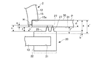
図5において、aは、車体パネルPの係止頭部15が通り抜けた側の面(係止頭部15側の面)30から弾性防水部材20の係止頭部側の面25までの寸法である。bは、支持板部13の想定される歪み量である。fは、上記寸法aから車体パネルPの厚さdを差し引いた寸法である。cは、上記寸法aから車体パネルPの厚さdを差し引いた上記寸法fに圧縮寸法eを足した高さ寸法である。
In FIG. 5, a is a dimension from the surface (surface on the locking
a'は、支持板部13が傾くことにより上記寸法fが大きくなるように支持板部13が上記寸法bだけ撓んだ際の、車体パネルPの係止頭部15側の面30から弾性防水部材20の係止頭部側の面25までの寸法である。f'は、上記寸法a'から車体パネルPの厚さdを差し引いた寸法である。c'は、支持板部13が寸法bだけ傾いたときの止水機能を維持するために必要な止水リップ部27の高さ寸法の設定値である。
a ′ is elastic from the
図5において、弾性防水部材20の止水リップ部27は、車体パネルPの係止頭部15側の面30から弾性防水部材20の係止頭部15側の面25までの寸法aから車体パネルPの厚さdを差し引いた寸法fに圧縮寸法eを足した高さ寸法cとなるように設けられている。
In FIG. 5, the water
高さ寸法cは、支持板部13が傾いた場合に寸法fよりも大きく変化する寸法f'よりも大きく設定されている。詳述すると、高さ寸法cは、上記寸法fが大きくなるように支持板部13が傾いたときの車体パネルPの係止頭部15側の面30から弾性防水部材20の係止頭部15側の面までの寸法a'から車体パネルPの厚さdを差し引いた寸法f'よりも大きく設定されている。
The height dimension c is set to be larger than a dimension f ′ that changes larger than the dimension f when the
本発明の実施形態に係るバンドクリップ2およびワイヤハーネス1は、上記高さ寸法cを有する止水リップ部27を設けた弾性防水部材20を有することで、図5に示す寸法bの範囲内で傾く限りにおいて、止水リップ部27と車体パネルPの面31との密着が維持され、弾性防水部材20による止水機能を維持することができる。
The
なお、この種のワイヤハーネスは、車体パネルPの係止孔Hへの取付前に、ケース内に収容され、保管や運搬が行われる。本発明の実施形態に係るワイヤハーネス1は、バンドクリップ2の弾性防水部材20が断面コの字形の軸部挿通孔22を有し、弾性防水部材20が軸部挿通孔22に挿通される支持板部13の外周部を両側から把持する構造である。このため、ワイヤハーネス1をケース内に出し入れする際に、弾性防水部材30が床面と接触して擦れながら移動しても支持板部13の外周部から弾性防水部材20が脱落することを防止できる。
In addition, this kind of wire harness is accommodated in a case before attachment to the locking hole H of the vehicle body panel P, and is stored and transported. In the wire harness 1 according to the embodiment of the present invention, the elastic
また、本発明の実施形態に係るワイヤハーネス1において、支持板部13の外周部を両側から把持するように弾性防水部材20を取り付けた構造により、弾性防止部材20を設けず支持部材13を直接車体パネルに密着するものに比べて防水性能を高めつつ、支持板部13、弾性防水部材20および車体パネルPの係止孔Hまでを含む貯水容量を小さくすることができる。
In the wire harness 1 according to the embodiment of the present invention, the elastic
なお、本発明の実施形態に係るバンドクリップ2およびワイヤハーネス1は、弾性防水部材20が支持板部13の形状に合わせて長円形状としているが、これに限らず、円形の弾性防水部材20に取り付ける場合には円形としてもよい。また、弾性防水部材20に設ける止水リップ部27も1周から2以上の周の週数で設けることができる。
In the
要は、本発明の実施形態に係る弾性防水部材20は、係止頭部15を容易に通すことが可能な大きな径を有する軸部挿通孔22を有し、バンドクリップ本体10が傾いたときにも、車体パネルPとの密着が維持される高さで止水リップ部27が軸部挿通孔22の外側を周回する止水リップ部27が律接されたものであればよい。
In short, the elastic
また、本発明の実施形態において、上記弾性防水部材20は、係止頭部15側の面にマーク用凸部28を設けた構成であってもよい。マーク用凸部28は、中心を通る長軸上と端軸上に位置するように設けられていて、弾性防水部材20が支持板部13に対して周方向にずれないように被さるための目印となっている。
In the embodiment of the present invention, the
このように、本発明の実施形態に係るバンドクリップ2およびワイヤハーネス1は、バンドクリップ本体10のクリップ部12に設けられる弾性防水部材20が、肉厚方向の中間部に形成された支持板部13の外周部を収容する外周部収容空間21と、外周部収容空間21を上下に貫通し軸部14を挿通する軸部挿通孔22と、係止頭部15側の面25に軸部挿通孔22の外側を周回するように突出して設けられ、取付時、車体パネルPの係止孔Hの周縁部に密着する止水リップ部27と、を有し、止水リップ部27は、バンド部11で保持する電線束Wの負荷が軸部14に曲げモーメントとして作用し軸部14が撓み支持板部13が傾いた場合にも、車体パネルPとの密着が維持される構成である。
As described above, in the
上記構成により、本発明の実施形態に係るバンドクリップ2およびワイヤハーネス1は、弾性防水部材20の軸部挿通孔22を係止頭部15を通し易い径とすることで、弾性防水部材20の支持板部13への取り付けが容易となり、取付時に弾性防水部材20を損傷する事態も回避できる。
With the configuration described above, the
また、弾性防水部材20は、軸14に作用する曲げモーメントにより支持板部13が傾いたときにも、止水リップ部27と車体パネルPとの密着が維持されるため、バンドクリップ本体10の支持板部13が傾いた場合でも確実に止水機能を果たすことができる。
In addition, the
また、本発明の実施形態では、上記構造のバンドクリップ2において、止水リップ部27は、車体パネルPの係止頭部15側の面30から弾性防水部材20の係止頭部15側の面25までの寸法aから車体パネルPの厚さdを差し引いた寸法fに圧縮寸法eを足した高さ寸法cであって、高さ寸法cは、支持板部13が傾いた場合に寸法fよりも大きく変化する寸法f'よりも大きく設定されている。
Further, in the embodiment of the present invention, in the
上記構成により、本発明の実施形態に係るバンドクリップ2は、支持板部13が傾いたときにも止水リップ部27と車体パネルPの面31との密着が維持され、弾性防水部材20による止水機能を維持することができる。
With the above configuration, the
なお、本発明は、上記実施形態に限定されるものでなく、特許請求の範囲の技術的範囲には、発明の要旨を逸脱しない範囲内で種々、設計変更した形態が含まれる。 Note that the present invention is not limited to the above-described embodiment, and the technical scope of the claims includes various design changes within the scope not departing from the gist of the invention.
本発明によれば、弾性防水部材の取り付けが容易で、取付中心からオフセットした位置に電線束を保持する場合にも確実な止水が行えるという効果を有し、弾性防水部材を備え止水機能を有するバンドクリップおよびこのバンドクリップを有するワイヤハーネスに有用である。 According to the present invention, it is easy to attach the elastic waterproof member, and has an effect that water can be reliably stopped even when the wire bundle is held at a position offset from the attachment center. It is useful for a band clip having a wire clip and a wire harness having the band clip.
1 ワイヤハーネス
2 バンドクリップ
10 バンドクリップ本体
11 バンド部
11a ベース部
12 クリップ部
13 支持板部
14 軸部
15 係止頭部
20 弾性防水部材
21 外周部収容空間
22 軸部挿通孔
25 係止頭部側の面
27 止水リップ部
28 マーク用凸部
30 係止頭部側の面
31 係止頭部の反対側の面
W 電線束
P 車体パネル
H 係止孔
DESCRIPTION OF SYMBOLS 1
Claims (3)
前記クリップ部は、車体パネルの係止孔の周縁部に対応するように前記ベース部に一体に設けられた支持板部と、前記支持板部の中央より延在された軸部と、前記軸部の先端より折り返して延在する係止頭部と、を有し、取付時に、前記軸部が車体パネルの係止孔を通る状態になるとともに、前記係止頭部が前記係止孔を通過しかつ前記係止孔の周縁部に係止するように構成され、
前記弾性防水部材は、肉厚方向の中間部に形成された前記支持板部の外周部を収容する外周部収容空間と、前記外周部収容空間を上下に貫通し前記軸部を挿通する軸部挿通孔と、前記係止頭部側の面に前記軸部挿通孔の外側を周回するように突出して設けられ、前記取付時、前記車体パネルの前記係止孔の周縁部に密着する止水リップ部と、を有し、
前記止水リップ部は、前記バンド部で保持する電線束の負荷が前記軸部に曲げモーメントとして作用し前記軸部が撓み前記支持板部が傾いた場合にも、前記車体パネルとの密着が維持されるようになっていることを特徴とするバンドクリップ。 A band clip body composed of a band portion and a clip portion integrally provided on the base portion of the band portion, and an annular elastic waterproof member,
The clip portion includes a support plate portion provided integrally with the base portion so as to correspond to a peripheral edge portion of the locking hole of the vehicle body panel, a shaft portion extending from the center of the support plate portion, and the shaft A locking head that is folded back and extended from the tip of the part, and when the shaft is attached, the shaft passes through the locking hole of the vehicle body panel, and the locking head has the locking hole. Configured to pass and lock to the peripheral edge of the locking hole;
The elastic waterproof member includes an outer peripheral portion accommodating space that accommodates an outer peripheral portion of the support plate portion formed at an intermediate portion in the thickness direction, and a shaft portion that vertically penetrates the outer peripheral portion accommodating space and passes through the shaft portion. An insertion hole and a water stop that is provided on the surface on the locking head side so as to protrude around the outer side of the shaft insertion hole, and is in close contact with the peripheral portion of the locking hole of the vehicle body panel during the mounting. A lip portion,
The water stop lip portion is in close contact with the vehicle body panel even when the load of the wire bundle held by the band portion acts as a bending moment on the shaft portion and the shaft portion is bent and the support plate portion is inclined. A band clip characterized by being maintained.
Priority Applications (1)
| Application Number | Priority Date | Filing Date | Title |
|---|---|---|---|
| JP2016022027A JP2017143608A (en) | 2016-02-08 | 2016-02-08 | Band clip and wiring harness |
Applications Claiming Priority (1)
| Application Number | Priority Date | Filing Date | Title |
|---|---|---|---|
| JP2016022027A JP2017143608A (en) | 2016-02-08 | 2016-02-08 | Band clip and wiring harness |
Publications (1)
| Publication Number | Publication Date |
|---|---|
| JP2017143608A true JP2017143608A (en) | 2017-08-17 |
Family
ID=59627953
Family Applications (1)
| Application Number | Title | Priority Date | Filing Date |
|---|---|---|---|
| JP2016022027A Pending JP2017143608A (en) | 2016-02-08 | 2016-02-08 | Band clip and wiring harness |
Country Status (1)
| Country | Link |
|---|---|
| JP (1) | JP2017143608A (en) |
Cited By (2)
| Publication number | Priority date | Publication date | Assignee | Title |
|---|---|---|---|---|
| CN108899822A (en) * | 2018-08-29 | 2018-11-27 | 安徽江淮汽车集团股份有限公司 | Harness fixing fastener component |
| WO2022264771A1 (en) * | 2021-06-14 | 2022-12-22 | 住友電装株式会社 | Wire harness |
-
2016
- 2016-02-08 JP JP2016022027A patent/JP2017143608A/en active Pending
Cited By (3)
| Publication number | Priority date | Publication date | Assignee | Title |
|---|---|---|---|---|
| CN108899822A (en) * | 2018-08-29 | 2018-11-27 | 安徽江淮汽车集团股份有限公司 | Harness fixing fastener component |
| CN108899822B (en) * | 2018-08-29 | 2019-12-17 | 安徽江淮汽车集团股份有限公司 | wire harness fixing buckle assembly |
| WO2022264771A1 (en) * | 2021-06-14 | 2022-12-22 | 住友電装株式会社 | Wire harness |
Similar Documents
| Publication | Publication Date | Title |
|---|---|---|
| US9488202B2 (en) | Clip | |
| US7294789B1 (en) | Retainer with band clip and cable holder | |
| US20110260025A1 (en) | Carpet clamp | |
| US20140151514A1 (en) | Corrugated tube clamp | |
| US20100084520A1 (en) | Clip | |
| EP2056419A2 (en) | Clamp for a plurality of wire harnesses | |
| JP2009038899A (en) | Supporting body for corrugate clamp, and corrugate clamp | |
| JP2012095434A (en) | Band clip | |
| JP2010151174A (en) | Clip | |
| US20160121822A1 (en) | Harness clip and system for clipping wiring harness | |
| JP2010159843A (en) | Clip for bolt | |
| JP2017143608A (en) | Band clip and wiring harness | |
| KR200473365Y1 (en) | Band cable | |
| US7435092B2 (en) | Retainer harness clip apparatus | |
| JP2015082855A (en) | Band clip attachment structure to corrugated tube | |
| JP2010266053A (en) | Clip | |
| JP7172972B2 (en) | Connector holder and wire harness | |
| US20150162733A1 (en) | Grommet with spreader mounting feature | |
| JP2017108588A (en) | Band clip and wire harness | |
| JP2014180152A (en) | Wire fixing structure and clamp | |
| JP2013143849A (en) | Harness clamp | |
| JP6254837B2 (en) | Fastener | |
| WO2016117365A1 (en) | Harness protector | |
| JP2018059610A (en) | Clip for locking of wire harness | |
| KR20170138965A (en) | Stud clip for fixing bus-bar |