JP2017142776A - Life management device and life management method - Google Patents

Life management device and life management method Download PDF

Info

Publication number
JP2017142776A
JP2017142776A JP2016226547A JP2016226547A JP2017142776A JP 2017142776 A JP2017142776 A JP 2017142776A JP 2016226547 A JP2016226547 A JP 2016226547A JP 2016226547 A JP2016226547 A JP 2016226547A JP 2017142776 A JP2017142776 A JP 2017142776A
Authority
JP
Japan
Prior art keywords
storage device
external memory
time
life
writing
Prior art date
Legal status (The legal status is an assumption and is not a legal conclusion. Google has not performed a legal analysis and makes no representation as to the accuracy of the status listed.)
Pending
Application number
JP2016226547A
Other languages
Japanese (ja)
Inventor
智広 南向
Tomohiro Onakata
智広 南向
Current Assignee (The listed assignees may be inaccurate. Google has not performed a legal analysis and makes no representation or warranty as to the accuracy of the list.)
Ricoh Co Ltd
Original Assignee
Ricoh Co Ltd
Priority date (The priority date is an assumption and is not a legal conclusion. Google has not performed a legal analysis and makes no representation as to the accuracy of the date listed.)
Filing date
Publication date
Application filed by Ricoh Co Ltd filed Critical Ricoh Co Ltd
Priority to US15/427,441 priority Critical patent/US10222982B2/en
Publication of JP2017142776A publication Critical patent/JP2017142776A/en
Pending legal-status Critical Current

Links

Images

Abstract

PROBLEM TO BE SOLVED: To make it possible to appropriately manage the life of a first storage device.SOLUTION: A life management device comprises: an integrated writing amount calculation part 12 that calculates the integrated amount of writing in an external memory (first storage device) every time writing is performed in the external memory; an information recording part 13 that records, in an NVRAM (second storage device), the integrated amount of writing in the external memory in association with a device ID (identification information) of the external memory and the date and time when the external memory is started to be used; and a life prediction part 14 that predicts the date and time when the external memory reaches the end of its life on the basis of the integrated amount of writing and the date and time when the external memory is started to be used recorded in the NVRAM.SELECTED DRAWING: Figure 3

Description

本発明は、寿命管理装置および寿命管理方法に関する。   The present invention relates to a life management apparatus and a life management method.

プリンタ、複写機、複合機などの画像形成装置においては、オプションプログラムとそれに伴うユーザデータなどを格納するメモリとして、安価で大容量のフラッシュメモリ、特にNAND型フラッシュメモリが利用されることが多い。   In image forming apparatuses such as printers, copiers, and multifunction machines, an inexpensive and large-capacity flash memory, particularly a NAND flash memory, is often used as a memory for storing an option program and accompanying user data.

NAND型フラッシュメモリは物理的な制約として、ブロックごとに書き換え回数に一定の制限がある。これを超えた場合、書き込まれたデータが正常に読めなくなるデータ化け(データ・リテンション性能の低下)や正常に書き込みができない(BAD BLOCKと呼ばれる)状態となる。したがって、NAND型フラッシュメモリは、書き換え回数の増加に伴って、正常に使用できない状態、つまりデバイスとしての寿命に近づくことになる。   The NAND flash memory has a certain limitation on the number of rewrites for each block as a physical restriction. If this is exceeded, the written data becomes garbled data (decrease in data retention performance) or cannot be written normally (called BAD BLOCK). Therefore, the NAND type flash memory approaches the state where it cannot be used normally, that is, the lifetime of the device, as the number of rewrites increases.

画像形成装置は製品の利用期間(製品寿命)が比較的長いため、製品そのものの寿命よりも前に、オプションプログラムやユーザデータなどを格納するメモリが寿命に達する場合がある。このような場合、メモリが寿命に達したことに気付かずに使用を続けると、オプションプログラムやユーザデータなどを消失してしまう虞がある。このため、メモリの寿命を適切に管理することが求められる。   Since an image forming apparatus has a relatively long product use period (product life), a memory for storing an option program or user data may reach the end of its life before the product itself. In such a case, if the memory is used without being aware that it has reached the end of its life, the option program, user data, etc. may be lost. For this reason, it is required to appropriately manage the lifetime of the memory.

SSD(Solid State Drive)やeMMC(embedded MultiMecia Card)などにおいては、SMART(Self−Monitoring and Reporting Technology)情報と呼ばれる管理情報を用いて書き換え回数やBAD BLOCK数などをユーザに知らせ、デバイスとしての寿命に達する前に交換などを促す仕組みがある。しかし、すべてのNAND型フラッシュメモリがSMART情報などの管理情報を通知する仕組みを持っているわけではない。例えばUSB(Universal Serial Bus)メモリやSDカードは管理情報について規格上規定されていないため、このような書き換え回数やBAD BLOCK数などを知るすべがない。   In SSD (Solid State Drive) and eMMC (embedded MultiMedia Card), etc., the number of rewrites and the number of BAD BLOCKs are used as management information called SMART (Self-Monitoring and Reporting Technology) information as the number of rewrites and the number of BAD BLOCK. There is a mechanism to encourage exchange before reaching the level. However, not all NAND flash memories have a mechanism for notifying management information such as SMART information. For example, since a USB (Universal Serial Bus) memory and an SD card are not regulated in terms of management information, there is no way of knowing the number of rewrites and the number of BAD BLOCKs.

特許文献1には、NAND型フラッシュメモリへのデータの書き込みにおいてBAD BLOCKが発生すると、該BAD BLOCKの発生に関するBAD BLOCK発生関連情報を取得して不揮発性記憶手段に記憶することが記載されている。この特許文献1に記載の技術によれば、NAND型フラッシュメモリのBAD BLOCK数が許容範囲を超えた場合や、BAD BLOCKの発生間隔が許容範囲よりも短くなった場合に、リサイクルNGのフラグを不揮発性記憶手段に記憶することで、NAND型フラッシュメモリのリサイクルの可否を判別することができる。   Patent Document 1 describes that when a BAD BLOCK occurs in writing data to a NAND flash memory, BAD BLOCK occurrence related information relating to the occurrence of the BAD BLOCK is acquired and stored in a nonvolatile storage means. . According to the technique described in Patent Document 1, when the number of BAD BLOCKs in the NAND flash memory exceeds the allowable range, or when the generation interval of BAD BLOCK becomes shorter than the allowable range, the flag of recycling NG is set. By storing in the nonvolatile storage means, it is possible to determine whether or not the NAND flash memory can be recycled.

しかし、特許文献1に記載の技術では、NAND型フラッシュメモリのリサイクルの可否を判別できるが、NAND型フラッシュメモリがいつ寿命に達するかまでは判別できず、NAND型フラッシュメモリの適切な管理という観点から改善の余地がある。   However, with the technique described in Patent Document 1, it is possible to determine whether or not the NAND flash memory can be recycled, but it is not possible to determine when the NAND flash memory reaches the end of its life, and a viewpoint of appropriate management of the NAND flash memory. There is room for improvement.

上述した課題を解決するために、本発明は、第1の記憶装置に対して書き込みを行うたびに前記第1の記憶装置に対する積算書き込み量を算出する積算書き込み量算出部と、前記積算書き込み量を、前記第1の記憶装置の識別情報および前記第1の記憶装置の利用開始日時と対応付けて第2の記憶装置に記録する第1の情報記録部と、前記第2の記憶装置に記録された前記積算書き込み量および前記利用開始日時に基づいて、前記第1の記憶装置の寿命到達日時を予測する寿命予測部と、を備える。   In order to solve the above-described problem, the present invention provides an integrated write amount calculation unit that calculates an integrated write amount for the first storage device each time data is written to the first storage device, and the integrated write amount. Is recorded in the second storage device, and the first information recording unit records the information in the second storage device in association with the identification information of the first storage device and the use start date and time of the first storage device. A life prediction unit that predicts a life arrival date and time of the first storage device based on the accumulated writing amount and the use start date and time.

本発明によれば、第1の記憶装置の寿命を適切に管理することができるという効果を奏する。   According to the present invention, there is an effect that the life of the first storage device can be appropriately managed.

図1は、画像形成装置のハードウェア構成例を示すブロック図である。FIG. 1 is a block diagram illustrating a hardware configuration example of an image forming apparatus. 図2は、フラッシュメモリの内部構成を説明する図である。FIG. 2 is a diagram illustrating the internal configuration of the flash memory. 図3は、画像形成装置の一機能として実現される寿命管理装置の機能的な構成例を示すブロック図である。FIG. 3 is a block diagram illustrating a functional configuration example of the life management apparatus realized as one function of the image forming apparatus. 図4は、NVRAMに記録される外部メモリごとの情報の一例を示す図である。FIG. 4 is a diagram illustrating an example of information for each external memory recorded in the NVRAM. 図5は、画像形成装置に対して外部メモリが接続されたときの寿命管理装置の動作例を示すフローチャートである。FIG. 5 is a flowchart illustrating an operation example of the life management apparatus when an external memory is connected to the image forming apparatus. 図6は、外部メモリに対する書き込み時における寿命管理装置の動作例を示すフローチャートである。FIG. 6 is a flowchart showing an operation example of the life management apparatus at the time of writing to the external memory. 図7は、寿命到達日時を予測するタイミングになったときの寿命管理装置の動作例を示すフローチャートである。FIG. 7 is a flowchart illustrating an example of the operation of the life management apparatus when it is time to predict the life arrival date and time. 図8は、情報の引き継ぎを指示する所定の操作が行われたときの寿命管理装置の動作例を示すフローチャートである。FIG. 8 is a flowchart illustrating an operation example of the life management apparatus when a predetermined operation for instructing information transfer is performed. 図9は、FATファイルシステムの概要を説明する図である。FIG. 9 is a diagram for explaining the outline of the FAT file system. 図10は、FAT内のクラスタ識別子を説明する図である。FIG. 10 is a diagram for explaining cluster identifiers in the FAT. 図11は、第2の実施形態の寿命管理装置の機能的な構成例を示すブロック図である。FIG. 11 is a block diagram illustrating a functional configuration example of the life management apparatus according to the second embodiment. 図12は、書き込み回数管理情報の一例を示す図である。FIG. 12 is a diagram illustrating an example of the write count management information. 図13は、外部メモリに書き込み回数管理情報を書き込む方法の一例を説明する図である。FIG. 13 is a diagram for explaining an example of a method for writing the write count management information in the external memory. 図14は、画像形成装置に対して外部メモリが接続されたときの寿命管理装置の動作例を示すフローチャートである。FIG. 14 is a flowchart illustrating an operation example of the life management apparatus when an external memory is connected to the image forming apparatus. 図15は、外部メモリに対する書き込み時における寿命管理装置の動作例を示すフローチャートである。FIG. 15 is a flowchart showing an operation example of the life management apparatus at the time of writing to the external memory. 図16は、寿命到達日時を予測するタイミングになったときの寿命管理装置の動作例を示すフローチャートである。FIG. 16 is a flowchart illustrating an operation example of the life management apparatus when it is time to predict the life arrival date and time. 図17は、画像形成装置の電源遮断時における寿命管理装置の動作例を示すフローチャートである。FIG. 17 is a flowchart illustrating an operation example of the life management apparatus when the image forming apparatus is powered off.

以下に添付図面を参照しながら、本発明に係る寿命管理装置および寿命管理方法の具体的な実施形態について詳しく説明する。以下で示す実施形態は、本発明に係る寿命管理装置および寿命管理方法を画像形成装置(「機器」の一態様)の一機能として実現した例である。ただし、本発明はこの例に限らず、画像形成装置以外の機器の機能として、あるいは機器から独立した装置として実現することも可能である。   Hereinafter, specific embodiments of a life management apparatus and a life management method according to the present invention will be described in detail with reference to the accompanying drawings. The embodiment described below is an example in which the life management apparatus and the life management method according to the present invention are realized as a function of an image forming apparatus (an aspect of “apparatus”). However, the present invention is not limited to this example, and can be realized as a function of a device other than the image forming apparatus or as a device independent of the device.

<第1の実施形態>
図1は、本実施形態の画像形成装置100のハードウェア構成例を示すブロック図である。本実施形態の画像形成装置100は、例えば図1に示すように、コントローラ110と、オペレーションパネル120と、エンジン130とを備える。
<First Embodiment>
FIG. 1 is a block diagram illustrating a hardware configuration example of an image forming apparatus 100 according to the present embodiment. The image forming apparatus 100 of the present embodiment includes a controller 110, an operation panel 120, and an engine 130, as shown in FIG.

コントローラ110は、画像形成装置100の動作を制御する制御装置である。コントローラ110は、例えば、制御基板上に、CPU(Central Processing Unit)111、DRAM(Dynamic Random Access Memory)112、ASIC(Application Specific Integrated Circuit)113、SSD114、NVRAM(Non−Volatile Random Access Memory)115、USBポート116およびSDカードスロット117などの各種電子部品を実装した構成とされる。USBポート116にはUSBメモリ140が装着され、SDカードスロット117にはSDカード150が装着される。   The controller 110 is a control device that controls the operation of the image forming apparatus 100. The controller 110 includes, for example, a CPU (Central Processing Unit) 111, a DRAM (Dynamic Random Access Memory) 112, an ASIC (Application Specific Integrated Circuit) 113, an SSD 114, an NVRAM (NVRAM) (NVRAM) Various electronic components such as a USB port 116 and an SD card slot 117 are mounted. A USB memory 140 is attached to the USB port 116, and an SD card 150 is attached to the SD card slot 117.

CPU111は、画像形成装置100の動作を制御するための各種プログラムを実行する演算装置である。DRAM112は、例えばCPU111がプログラムの実行時にワークエリアとして利用するメモリである。ASIC113は、各種の画像処理を実行したり各種の入出力インタフェース機能を実現したりする集積回路である。SSD114は、例えばシステム起動用のプログラムを格納する。NVRAM115は、画像形成装置100の電源がオフしても記憶しておく必要のある各種データを記憶する、書き換え制限のない不揮発性メモリである。本実施形態では、USBメモリ140やSDカード150に対する積算書き込み量が、USBメモリ140やSDカード150の識別情報(デバイスID)および利用開始日時と対応付けて、このNVRAM115に記録される。   The CPU 111 is an arithmetic device that executes various programs for controlling the operation of the image forming apparatus 100. The DRAM 112 is a memory used as a work area when the CPU 111 executes a program, for example. The ASIC 113 is an integrated circuit that executes various image processes and implements various input / output interface functions. The SSD 114 stores a system startup program, for example. The NVRAM 115 is a non-volatile memory with no rewrite restriction that stores various data that needs to be stored even when the power of the image forming apparatus 100 is turned off. In the present embodiment, the cumulative amount written to the USB memory 140 or the SD card 150 is recorded in the NVRAM 115 in association with the identification information (device ID) and the use start date and time of the USB memory 140 or the SD card 150.

USBポート116は、USBメモリ140をコントローラ110に接続するためのインタフェースである。USBメモリ140は、ユーザが任意に使用するメモリであり、画像形成装置100に対して外付けで接続されるフラッシュメモリである。SDカードスロット117は、SDカード150をコントローラ110に接続するためのインタフェースである。SDカード150は、オプションプログラムなどを格納するメモリであり、画像形成装置100に対して外付けで接続されるフラッシュメモリである。以下では、画像形成装置100に対して外付けで接続されるUSBメモリ140とSDカード150を総称する場合は、外部メモリ160と呼ぶ。   The USB port 116 is an interface for connecting the USB memory 140 to the controller 110. The USB memory 140 is a memory that is arbitrarily used by the user, and is a flash memory that is externally connected to the image forming apparatus 100. The SD card slot 117 is an interface for connecting the SD card 150 to the controller 110. The SD card 150 is a memory that stores an option program and the like, and is a flash memory that is externally connected to the image forming apparatus 100. Hereinafter, the USB memory 140 and the SD card 150 that are externally connected to the image forming apparatus 100 are collectively referred to as an external memory 160.

オペレーションパネル120は、コントローラ110による制御のもとで、各種の情報を表示してユーザに知らせたり、ユーザによる各種の入力操作を受け付けてコントローラ110に伝達したりするユーザインタフェースである。エンジン130は、コントローラ110による制御のもとで原稿の読み取りを行うスキャナエンジンや、コントローラ110による制御のもとで記録紙などに画像形成を行うプロッタエンジンなどを含む。   The operation panel 120 is a user interface that displays various types of information and notifies the user under the control of the controller 110, and receives various input operations by the user and transmits them to the controller 110. The engine 130 includes a scanner engine that reads a document under the control of the controller 110, a plotter engine that forms an image on a recording sheet or the like under the control of the controller 110, and the like.

本実施形態では、画像形成装置100に対して外付けで接続されるフラッシュメモリである外部メモリ160(USBメモリ140およびSDカード150)が「第1の記憶装置」に相当し、画像形成装置100に実装された書き換え制限のない不揮発性メモリであるNVRAM115が「第2の記憶装置」に相当する。そして、本実施形態の画像形成装置100は、外部メモリ160に対する書き込みが行われるたびに、外部メモリ160に対する積算書き込み量を算出してNVRAM115に記録し、外部メモリ160に対する積算書き込み量が所定量に達する寿命到達日時を予測する、寿命管理装置としての機能を持つ。   In the present embodiment, the external memory 160 (USB memory 140 and SD card 150), which is a flash memory connected externally to the image forming apparatus 100, corresponds to the “first storage device”. The NVRAM 115, which is a non-volatile memory with no rewrite restriction, is equivalent to the “second storage device”. The image forming apparatus 100 according to the present embodiment calculates an accumulated write amount to the external memory 160 and records it in the NVRAM 115 every time writing to the external memory 160 is performed, and the accumulated write amount to the external memory 160 becomes a predetermined amount. It has a function as a life management device that predicts the life arrival date and time.

図2は、フラッシュメモリの内部構成を説明する図である。フラッシュメモリの記憶領域は、図2に示すように、複数のブロック(図2ではBlock0からBlock1023)に分かれており、各ブロックは複数のページ(図2ではpage0からpage63)から構成されている。フラッシュメモリに対するデータの書き込みはページ単位で行われ、データの消去はブロック単位で行われる。また、データの上書きを行うことはできず、データが書き込まれたブロックに新たなデータを書き込む場合は、そのブロックのデータを一旦消去してからでないと新たなデータの書き込みができない。   FIG. 2 is a diagram illustrating the internal configuration of the flash memory. As shown in FIG. 2, the storage area of the flash memory is divided into a plurality of blocks (Block 0 to Block 1023 in FIG. 2), and each block is composed of a plurality of pages (page 0 to page 63 in FIG. 2). Data is written to the flash memory in units of pages, and data is erased in units of blocks. In addition, data cannot be overwritten. When new data is written in a block in which data is written, new data cannot be written unless the data in the block is once erased.

フラッシュメモリに対するデータの書き込みや読み出しは、OS(オペレーションシステム)上で動作するソフトウェアであるデバイスドライバにより行われる。本実施形態の画像形成装置100では、例えば、コントローラ110のCPU111がOS上でUSBメモリ140に対応するデバイスドライバを動作させることで、USBポート116に装着されたUSBメモリ140に対するデータの書き込みや読み出しが行われる。また、コントローラ110のCPU111がOS上でSDカード150に対応するデバイスドライバを動作させることで、SDカードスロット117に装着されたSDカード150に対するデータの書き込みや読み出しが行われる。   Data is written to and read from the flash memory by a device driver that is software operating on an OS (operation system). In the image forming apparatus 100 according to the present embodiment, for example, the CPU 111 of the controller 110 operates a device driver corresponding to the USB memory 140 on the OS to write or read data to or from the USB memory 140 attached to the USB port 116. Is done. In addition, when the CPU 111 of the controller 110 operates a device driver corresponding to the SD card 150 on the OS, data is written to and read from the SD card 150 installed in the SD card slot 117.

図3は、本実施形態の画像形成装置100の一機能として実現される寿命管理装置100Aの機能的な構成例を示すブロック図である。本実施形態の画像形成装置100では、例えば、コントローラ110のCPU111が、寿命管理方法の実行手順をプログラムコードとして記述した所定のプログラムを実行することにより、例えば図3に示すように、識別情報取得部11、積算書き込み量算出部12、情報記録部13(「第1の情報記録部」に相当)、寿命予測部14、表示制御部15、書き込み禁止制御部16(「第1の書き込み禁止制御部」に相当)、情報書き込み制御部17(「第1の情報書き込み制御部」に相当)などの寿命管理装置100Aを構成する機能的な構成要素が実現される。   FIG. 3 is a block diagram illustrating a functional configuration example of the life management apparatus 100A realized as one function of the image forming apparatus 100 of the present embodiment. In the image forming apparatus 100 of the present embodiment, for example, the CPU 111 of the controller 110 executes a predetermined program in which the execution procedure of the life management method is described as a program code, thereby obtaining identification information as shown in FIG. 11, integrated write amount calculation unit 12, information recording unit 13 (corresponding to “first information recording unit”), life prediction unit 14, display control unit 15, write prohibition control unit 16 (“first write prohibition control”) Functional component constituting the life management apparatus 100A such as the information writing control unit 17 (corresponding to the “first information writing control unit”).

識別情報取得部11は、画像形成装置100に対して外部メモリ160が接続されたときに、その外部メモリ160の識別情報(デバイスID)を取得する機能モジュールである。識別情報取得部11は、画像形成装置100に接続された外部メモリ160が固有のデバイスIDを保持する場合は、このデバイスIDを外部メモリ160から読み取ることで、外部メモリ160のデバイスIDを取得する。また、識別情報取得部11は、画像形成装置100に接続された外部メモリ160がデバイスIDを保持していない場合は、例えば、外部メモリ160が画像形成装置100に接続されたときの現在時刻などに基づいて、この外部メモリ160のデバイスIDを生成する。この場合、識別情報取得部11は、生成したデバイスIDを、デバイスドライバを通じて外部メモリ160に書き込む処理を行う。   The identification information acquisition unit 11 is a functional module that acquires identification information (device ID) of the external memory 160 when the external memory 160 is connected to the image forming apparatus 100. When the external memory 160 connected to the image forming apparatus 100 holds a unique device ID, the identification information acquisition unit 11 acquires the device ID of the external memory 160 by reading this device ID from the external memory 160. . Further, when the external memory 160 connected to the image forming apparatus 100 does not hold the device ID, the identification information acquisition unit 11, for example, the current time when the external memory 160 is connected to the image forming apparatus 100, etc. Based on the above, the device ID of the external memory 160 is generated. In this case, the identification information acquisition unit 11 performs a process of writing the generated device ID into the external memory 160 through the device driver.

積算書き込み量算出部12は、外部メモリ160に対して書き込みを行うたびに外部メモリ160に対する積算書き込み量を算出する機能モジュールである。積算書き込み量算出部12は、デバイスドライバによって外部メモリ160に対するデータの書き込みが行われると、その書き込み量をカウントする。そして、積算書き込み量算出部12は、NVRAM115を参照し、識別情報取得部11が取得したデバイスIDに対応付く積算書き込み量がNVRAM115に記録されていれば、NVRAM115に記録されていた積算書き込み量に対して今回カウントした書き込み量を加算した値を、新たな積算書き込み量として算出する。なお、識別情報取得部11が取得したデバイスIDに対応付く積算書き込み量がNVRAM115に記録されていない場合は、今回カウントした書き込み量が、そのまま積算書き込み量となる。   The integrated write amount calculation unit 12 is a functional module that calculates an integrated write amount for the external memory 160 each time data is written to the external memory 160. When the device driver writes data to the external memory 160, the integrated write amount calculation unit 12 counts the write amount. Then, the cumulative write amount calculation unit 12 refers to the NVRAM 115, and if the cumulative write amount corresponding to the device ID acquired by the identification information acquisition unit 11 is recorded in the NVRAM 115, the cumulative write amount recorded in the NVRAM 115 is used. On the other hand, a value obtained by adding the writing amount counted this time is calculated as a new integrated writing amount. If the cumulative write amount associated with the device ID acquired by the identification information acquisition unit 11 is not recorded in the NVRAM 115, the write amount counted this time becomes the cumulative write amount as it is.

情報記録部13は、積算書き込み量算出部12が算出した積算書き込み量を、識別情報取得部11が取得した外部メモリ160のデバイスIDと、外部メモリ160の利用開始日時とに対応付けて、NVRAM115に記録する機能モジュールである。情報記録部13は、NVRAM115を参照し、識別情報取得部11が取得したデバイスIDに対応付く積算書き込み量がNVRAM115に記録されていれば、NVRAM115に記録されていた積算書き込み量を、積算書き込み量算出部12が算出した新たな積算書き込み量で更新する。一方、識別情報取得部11が取得したデバイスIDに対応付く積算書き込み量がNVRAM115に記録されていない場合は、情報記録部13は、例えば、外部メモリ160が画像形成装置100に接続されたときの現在時刻を利用開始日時とし、識別情報取得部11が取得したデバイスIDと、利用開始日時(現在時刻)と、積算書き込み量算出部12が算出した積算書き込み量(今回カウントした書き込み量)とを対応付けて、NVRAM115に記録する。   The information recording unit 13 associates the integrated write amount calculated by the integrated write amount calculating unit 12 with the device ID of the external memory 160 acquired by the identification information acquiring unit 11 and the use start date and time of the external memory 160, and the NVRAM 115. It is a functional module to record in. The information recording unit 13 refers to the NVRAM 115, and if the cumulative write amount associated with the device ID acquired by the identification information acquisition unit 11 is recorded in the NVRAM 115, the cumulative write amount recorded in the NVRAM 115 is used as the cumulative write amount. Update with the new integrated writing amount calculated by the calculation unit 12. On the other hand, when the cumulative writing amount corresponding to the device ID acquired by the identification information acquisition unit 11 is not recorded in the NVRAM 115, the information recording unit 13 displays, for example, when the external memory 160 is connected to the image forming apparatus 100. Using the current time as the use start date and time, the device ID acquired by the identification information acquisition unit 11, the use start date and time (current time), and the integrated write amount calculated by the integrated write amount calculation unit 12 (the write amount counted this time) Correspondingly, it is recorded in the NVRAM 115.

図4は、NVRAM115に記録される外部メモリ160ごとの情報の一例を示す図である。NVRAM115には、例えば図4に示すように、外部メモリ160ごとの情報20として、外部メモリ160のデバイスIDを示す情報21と、外部メモリ160の利用開始日時を示す情報22と、外部メモリ160の積算書き込み量を示す情報23とが、各々対応付けられて記録される。   FIG. 4 is a diagram illustrating an example of information for each external memory 160 recorded in the NVRAM 115. For example, as shown in FIG. 4, the NVRAM 115 includes information 21 indicating the device ID of the external memory 160, information 22 indicating the use start date and time of the external memory 160, Information 23 indicating the cumulative writing amount is recorded in association with each other.

なお、識別情報取得部11が取得したデバイスIDに対応付く積算書き込み量がNVRAM115に記録されておらず、外部メモリ160が利用開始日時と積算書き込み量を保持している場合は、情報記録部13は、外部メモリ160が保持する利用開始日時と積算書き込み量を、識別情報取得部11が取得したデバイスIDに対応付けて、NVRAM115に記録する。これにより、後述する画像形成装置100の交換時における情報の引き継ぎが実現される。   If the cumulative write amount associated with the device ID acquired by the identification information acquiring unit 11 is not recorded in the NVRAM 115 and the external memory 160 holds the use start date and cumulative write amount, the information recording unit 13 Records the use start date and time and the accumulated writing amount held in the external memory 160 in the NVRAM 115 in association with the device ID acquired by the identification information acquisition unit 11. As a result, information transfer when the image forming apparatus 100 described later is replaced is realized.

寿命予測部14は、NVRAM115に記録された外部メモリ160の積算書き込み量と利用開始日時とに基づいて、外部メモリ160の積算書き込み量が所定量に達する寿命到達日時を予測する機能モジュールである。寿命予測部14による寿命到達日時の予測は、例えば、画像形成装置100の電源投入時、画像形成装置100の電源が遮断されるとき、外部メモリ160が装着されたとき、外部メモリ160が取り外されるとき、予め定めた時刻、予め定めた時間間隔で定期的になど、所定のタイミングで実施される。   The life prediction unit 14 is a functional module that predicts the life arrival date and time when the accumulated write amount of the external memory 160 reaches a predetermined amount based on the accumulated write amount of the external memory 160 and the use start date and time recorded in the NVRAM 115. For example, when the image forming apparatus 100 is turned on, when the power of the image forming apparatus 100 is turned off, when the external memory 160 is attached, the external memory 160 is removed. Sometimes, it is carried out at a predetermined timing, such as at a predetermined time or periodically at a predetermined time interval.

寿命予測部14は、寿命到達日時を予測するタイミングになると、NVRAM115を参照し、予測の対象となる外部メモリ160、つまり、画像形成装置100に接続されている外部メモリ160のデバイスIDに対応付く積算書き込み量と利用開始日時とをNVRAM115から読み出す。ここで、NVRAM115から読み出した積算書き込み量がすでに所定量以上となっていれば、寿命予測部14は、外部メモリ160がすでに寿命に達していると判定する。一方、NVRAM115から読み出した積算書き込み量が所定量未満であれば、寿命予測部14は、まず、NVRAM115から読み出した利用開始日時と現在時刻とに基づいて、外部メモリ160の利用を開始してからの経過時間を算出し、NVRAM115から読み出した積算書き込み量を経過時間で除算することにより、外部メモリ160に対する単位時間(例えば1時間)あたりの平均書き込み量を算出する。そして、寿命予測部14は、積算書き込み量と所定量との差分を単位時間あたりの平均書き込み量で除算することにより、外部メモリ160の積算書き込み量が所定量に達する寿命到達日時を予測する。   The life prediction unit 14 refers to the NVRAM 115 when it is time to predict the life arrival date and time, and corresponds to the device ID of the external memory 160 to be predicted, that is, the external memory 160 connected to the image forming apparatus 100. The accumulated writing amount and the use start date and time are read from the NVRAM 115. Here, if the accumulated write amount read from the NVRAM 115 is already equal to or greater than the predetermined amount, the life prediction unit 14 determines that the external memory 160 has already reached the life. On the other hand, if the accumulated write amount read from the NVRAM 115 is less than the predetermined amount, the life prediction unit 14 first starts using the external memory 160 based on the use start date and time and the current time read from the NVRAM 115. , And the average writing amount per unit time (for example, one hour) to the external memory 160 is calculated by dividing the cumulative writing amount read from the NVRAM 115 by the elapsed time. Then, the life prediction unit 14 predicts the life arrival date and time when the accumulated write amount of the external memory 160 reaches the predetermined amount by dividing the difference between the accumulated write amount and the predetermined amount by the average write amount per unit time.

なお、外部メモリ160の寿命は、上述したように、外部メモリ160に対する書き込み回数によって決まる。本実施形態では、外部メモリ160に対する積算書き込み量を扱うため、必ずしも外部メモリ160の寿命を正確に判定することにならない。しかし、外部メモリ160に対する積算書き込み量は書き込み回数との相関が高いため、外部メモリ160に対する積算書き込み量に基づいて、外部メモリ160の寿命を高い精度で予測することができる。   Note that the lifetime of the external memory 160 is determined by the number of writes to the external memory 160 as described above. In the present embodiment, since the cumulative writing amount to the external memory 160 is handled, the life of the external memory 160 is not necessarily determined accurately. However, since the cumulative write amount to the external memory 160 has a high correlation with the number of writes, the life of the external memory 160 can be predicted with high accuracy based on the cumulative write amount to the external memory 160.

表示制御部15は、寿命予測部14が予測した寿命到達日時をオペレーションパネル120(「表示装置」の一態様)に表示させるように制御する機能モジュールである。表示制御部15は、例えば、寿命予測部14が予測した寿命到達日時を、テキストデータによるメッセージとしてオペレーションパネル120に表示させる。また、表示制御部15は、寿命予測部14が予測した寿命到達日時が現在から所定期間内(例えば3か月以内)の日時であれば、外部メモリ160の寿命が近い旨の警告メッセージとともに、寿命予測部14が予測した寿命到達日時をオペレーションパネル120に表示させるようにしてもよい。   The display control unit 15 is a functional module that controls the life panel date and time predicted by the life prediction unit 14 to be displayed on the operation panel 120 (an aspect of “display device”). For example, the display control unit 15 causes the operation panel 120 to display the life arrival date and time predicted by the life prediction unit 14 as a message using text data. The display control unit 15 also displays a warning message indicating that the life of the external memory 160 is near if the life arrival date and time predicted by the life prediction unit 14 is within a predetermined period (for example, within 3 months) from the present time. The life arrival date and time predicted by the life prediction unit 14 may be displayed on the operation panel 120.

また、表示制御部15は、外部メモリ160がすでに寿命に達していると寿命予測部14が判定した場合に、外部メモリ160が利用できないことを示すエラーメッセージなどをオペレーションパネル120に表示させるようにしてもよい。さらに、表示制御部15は、画像形成装置100に接続された外部メモリ160が書き込み禁止モードに設定されている場合に、外部メモリ160が利用できないことを示すエラーメッセージなどをオペレーションパネル120に表示させるようにしてもよい。   In addition, the display control unit 15 causes the operation panel 120 to display an error message indicating that the external memory 160 cannot be used when the life prediction unit 14 determines that the external memory 160 has already reached the end of its life. May be. Further, the display control unit 15 causes the operation panel 120 to display an error message indicating that the external memory 160 cannot be used when the external memory 160 connected to the image forming apparatus 100 is set to the write-protect mode. You may do it.

書き込み禁止制御部16は、積算書き込み量算出部12が算出した積算書き込み量が所定量に達した外部メモリ160に対する書き込みを禁止するように制御する機能モジュールである。書き込み禁止制御部16は、例えば、積算書き込み量算出部12が算出した積算書き込み量が所定量に達した外部メモリ160、つまり、寿命予測部14がすでに寿命に達していると判定した外部メモリ160を書き込み禁止モードに設定することにより、この外部メモリ160に対する書き込みを禁止することができる。なお、書き込み禁止モードの設定は、例えば、外部メモリ160に設けられた所定のスイッチをオンすることで実現してもよいし、予め定めた所定のフラグをオンすることで実現してもよい。また、外部メモリ160に対応するデバイスドライバの設定を書き込み禁止モードとすることで、外部メモリ160に対する書き込みを禁止するように制御してもよい。   The write prohibition control unit 16 is a functional module that controls to prohibit writing to the external memory 160 when the cumulative write amount calculated by the cumulative write amount calculation unit 12 reaches a predetermined amount. The write prohibition control unit 16, for example, the external memory 160 in which the cumulative writing amount calculated by the cumulative writing amount calculation unit 12 has reached a predetermined amount, that is, the external memory 160 that the life prediction unit 14 has determined has already reached the life. By setting to the write prohibit mode, writing to the external memory 160 can be prohibited. The setting of the write prohibition mode may be realized by turning on a predetermined switch provided in the external memory 160, or may be realized by turning on a predetermined flag. Further, the setting of the device driver corresponding to the external memory 160 may be controlled to be prohibited from writing to the external memory 160 by setting the device driver to the write prohibiting mode.

情報書き込み制御部17は、所定の操作に応じて、NVRAM115に記録された積算書き込み量および利用開始日時を外部メモリ160に書き込むように制御する機能モジュールである。画像形成装置100を古いものから新しいものに交換する場合、古い画像形成装置100で使用していた外部メモリ160をそのまま新しい画像形成装置100でも使用することがある。この場合、古い画像形成装置100のNVRAM115に記録された外部メモリ160の積算書き込み量や利用開始日時の情報を、新しい画像形成装置100に引き継がせることが望ましい。このような画像形成装置100の交換時における情報の引き継ぎを実現するため、ユーザが情報の引き継ぎを指示する所定の操作を行ったときに、情報書き込み制御部17は、画像形成装置100に接続されている外部メモリ160のデバイスIDに対応付く積算書き込み量および利用開始日時をNVRAM115から読み出して、この積算書き込み量および利用開始日時を、デバイスドライバを通じて外部メモリ160に書き込む処理を行う。   The information writing control unit 17 is a functional module that controls to write the accumulated writing amount and use start date and time recorded in the NVRAM 115 to the external memory 160 in accordance with a predetermined operation. When the image forming apparatus 100 is exchanged from an old one to a new one, the external memory 160 used in the old image forming apparatus 100 may be used in the new image forming apparatus 100 as it is. In this case, it is desirable to allow the new image forming apparatus 100 to take over the accumulated writing amount of the external memory 160 and use start date / time information recorded in the NVRAM 115 of the old image forming apparatus 100. In order to realize such information transfer when the image forming apparatus 100 is exchanged, the information writing control unit 17 is connected to the image forming apparatus 100 when a user performs a predetermined operation instructing information transfer. The integrated write amount and use start date and time associated with the device ID of the external memory 160 are read from the NVRAM 115, and the integrated write amount and use start date and time are written to the external memory 160 through the device driver.

外部メモリ160に書き込まれた積算書き込み量および利用開始日時は、外部メモリ160に保持され、その後、この外部メモリ160が新しい画像形成装置100に接続されたときに、新しい画像形成装置100の情報記録部13によって新しい画像形成装置100のNVRAM115に記録される。これにより、画像形成装置100の交換時における情報の引き継ぎが実現される。   The accumulated writing amount and use start date and time written in the external memory 160 are held in the external memory 160, and when the external memory 160 is connected to the new image forming apparatus 100, information recording of the new image forming apparatus 100 is performed. The image is recorded in the NVRAM 115 of the new image forming apparatus 100 by the unit 13. As a result, information transfer at the time of replacement of the image forming apparatus 100 is realized.

次に、上述した各機能モジュールの組み合わせとして構成される本実施形態の寿命管理装置100Aの動作について、図5乃至図8を参照して説明する。   Next, the operation of the life management apparatus 100A according to the present embodiment configured as a combination of the above-described functional modules will be described with reference to FIGS.

図5は、画像形成装置100に対して外部メモリ160が接続されたときの寿命管理装置100Aの動作例を示すフローチャートである。この図5のフローチャートで示す一連の処理は、画像形成装置100に対して外部メモリ160が接続されたことが検知されるたびに実行される。   FIG. 5 is a flowchart illustrating an operation example of the life management apparatus 100 </ b> A when the external memory 160 is connected to the image forming apparatus 100. A series of processes shown in the flowchart of FIG. 5 is executed every time it is detected that the external memory 160 is connected to the image forming apparatus 100.

画像形成装置100に対して外部メモリ160が接続されたことが検知されると、まず、外部メモリ160が固有のデバイスIDを保持しているか否かが、識別情報取得部11によって判定される(ステップS101)。そして、外部メモリ160が固有のデバイスIDを保持している場合(ステップS101:Yes)、識別情報取得部11は、デバイスIDを外部メモリ160から読み取る(ステップS102)。一方、外部メモリ160が固有のデバイスIDを保持していなければ(ステップS101:No)、識別情報取得部11は、例えば現在時刻などに基づいて外部メモリ160のデバイスIDを生成し(ステップS103)、生成したデバイスIDを外部メモリ160に書き込む(ステップS104)。   When it is detected that the external memory 160 is connected to the image forming apparatus 100, first, the identification information acquisition unit 11 determines whether or not the external memory 160 holds a unique device ID ( Step S101). If the external memory 160 holds a unique device ID (step S101: Yes), the identification information acquisition unit 11 reads the device ID from the external memory 160 (step S102). On the other hand, if the external memory 160 does not hold a unique device ID (step S101: No), the identification information acquisition unit 11 generates a device ID of the external memory 160 based on the current time, for example (step S103). The generated device ID is written in the external memory 160 (step S104).

次に、情報記録部13が、現在時刻を外部メモリ160の利用開始日時と判断し、ステップS102で外部メモリ160から読み取られたデバイスIDまたはステップS103で生成されたデバイスIDと、外部メモリ160の利用開始日時(現在時刻)とを、NVRAM115に記録する(ステップS105)。なお、外部メモリ160のデバイスIDと利用開始日時がすでにNVRAM115に記録されている場合は、ステップS105の処理はスキップされる。   Next, the information recording unit 13 determines that the current time is the use start date and time of the external memory 160, the device ID read from the external memory 160 in step S 102 or the device ID generated in step S 103, and the external memory 160 The use start date and time (current time) is recorded in the NVRAM 115 (step S105). If the device ID and the use start date / time of the external memory 160 are already recorded in the NVRAM 115, the process of step S105 is skipped.

次に、情報記録部13は、外部メモリ160が利用開始日時と積算書き込み量を保持しているか否かを判定する(ステップS106)。そして、外部メモリ160が利用開始日時と積算書き込み量を保持している場合(ステップS106:Yes)、情報記録部13は、外部メモリ160からNVRAM115に利用開始日時と積算書き込み量をコピーし(ステップS107)、その後、外部メモリ160が保持する利用開始日時と積算書き込み量を消去する(ステップS108)。一方、外部メモリ160が利用開始日時と積算書き込み量を保持していなければ(ステップS106:No)、ステップS107およびステップS108の処理はスキップされる。   Next, the information recording unit 13 determines whether or not the external memory 160 holds the use start date and time and the cumulative writing amount (step S106). When the external memory 160 holds the use start date and time and the accumulated write amount (step S106: Yes), the information recording unit 13 copies the use start date and time and the accumulated write amount from the external memory 160 to the NVRAM 115 (step S106). Thereafter, the use start date and time and the accumulated writing amount held in the external memory 160 are erased (step S108). On the other hand, if the external memory 160 does not hold the use start date and time and the cumulative writing amount (step S106: No), the processing of step S107 and step S108 is skipped.

そして最後に、積算書き込み量算出部12が外部メモリ160に対応するデバイスドライバを書き込み管理モードで動作させ(ステップS109)、一連の処理が終了する。   Finally, the integrated write amount calculation unit 12 operates the device driver corresponding to the external memory 160 in the write management mode (step S109), and the series of processing ends.

図6は、外部メモリ160に対する書き込み時における寿命管理装置100Aの動作例を示すフローチャートである。この図6のフローチャートで示す一連の処理は、書き込み管理モードで動作するデバイスドライバが書き込み命令を受けるたびに実行される。   FIG. 6 is a flowchart showing an operation example of the life management apparatus 100A at the time of writing to the external memory 160. The series of processing shown in the flowchart of FIG. 6 is executed every time a device driver operating in the write management mode receives a write command.

外部メモリ160に対応するデバイスドライバが書き込み命令を受けた場合、まず、外部メモリ160が書き込み禁止モードになっているか否かが、表示制御部15によって判定される(ステップS201)。そして、外部メモリ160が書き込み禁止モードになっている場合(ステップS201:Yes)、表示制御部15が、外部メモリ160が利用できないことを示すエラーメッセージなどをオペレーションパネル120に表示させ(ステップ202)、一連の処理が終了する。   When the device driver corresponding to the external memory 160 receives a write command, first, the display control unit 15 determines whether or not the external memory 160 is in the write inhibit mode (step S201). If the external memory 160 is in the write-protect mode (step S201: Yes), the display control unit 15 causes the operation panel 120 to display an error message indicating that the external memory 160 cannot be used (step 202). The series of processing ends.

一方、外部メモリ160が書き込み禁止モードになっていなければ(ステップS201:No)、デバイスドライバによって外部メモリ160に対するデータの書き込みが行われる。このとき、積算書き込み量算出部12が、デバイスドライバによる外部メモリ160へのデータの書き込み量をカウントする(ステップ203)。そして、積算書き込み量算出部12は、ステップS203でカウントした書き込み量を、NVRAM115に記録されている積算書き込み量に加算して、今回の書き込みによって増加した外部メモリ160の積算書き込み量を算出する(ステップS204)。そして、情報記録部13が、NVRAM115に記録されている積算書き込み量を、ステップS204で算出された積算書き込み量で更新し(ステップS205)、一連の処理が終了する。   On the other hand, if the external memory 160 is not in the write inhibit mode (step S201: No), the device driver writes data to the external memory 160. At this time, the integrated writing amount calculation unit 12 counts the amount of data written to the external memory 160 by the device driver (step 203). Then, the cumulative writing amount calculation unit 12 adds the writing amount counted in step S203 to the cumulative writing amount recorded in the NVRAM 115, and calculates the cumulative writing amount of the external memory 160 increased by the current writing ( Step S204). Then, the information recording unit 13 updates the cumulative writing amount recorded in the NVRAM 115 with the cumulative writing amount calculated in Step S204 (Step S205), and the series of processes is completed.

なお、外部メモリ160に対する書き込み時に、この外部メモリ160の積算書き込み量がNVRAM115に記録されていない場合は、積算書き込み量算出部12がステップS203でカウントした書き込み量が、外部メモリ160の積算書き込み量として扱われる。この場合、情報記録部13は、ステップS203でカウントされた書き込み量を外部メモリ160の積算書き込み量として、NVRAM115に記録する。   If the cumulative write amount of the external memory 160 is not recorded in the NVRAM 115 when writing to the external memory 160, the write amount counted by the cumulative write amount calculation unit 12 in step S203 is the cumulative write amount of the external memory 160. Are treated as In this case, the information recording unit 13 records the amount of writing counted in step S203 in the NVRAM 115 as the accumulated amount of writing in the external memory 160.

図7は、寿命到達日時を予測するタイミングになったときの寿命管理装置100Aの動作例を示すフローチャートである。この図7のフローチャートで示す一連の処理は、寿命到達日時を予測するタイミングとして予め定められた所定のタイミングになるたびに実行される。   FIG. 7 is a flowchart illustrating an example of the operation of the life management apparatus 100A when it is time to predict the life arrival date and time. The series of processes shown in the flowchart of FIG. 7 is executed every time a predetermined timing is set as a timing for predicting the life arrival date and time.

寿命到達日時を予測するタイミングになると、寿命予測部14によりNVRAM115が参照され、画像形成装置100に接続されている外部メモリ160の積算書き込み量が所定量に達しているか否かが判定される(ステップS301)。そして、外部メモリ160の積算書き込み量が所定量に達していれば(ステップS301:Yes)、表示制御部15が、外部メモリ160が利用できないことを示すエラーメッセージなどをオペレーションパネル120に表示させる(ステップS302)。また、書き込み禁止制御部16が、外部メモリ160を書き込み禁止モードに設定し(ステップS303)、一連の処理が終了する。   When it is time to predict the life arrival date and time, the life prediction unit 14 refers to the NVRAM 115 and determines whether or not the cumulative writing amount of the external memory 160 connected to the image forming apparatus 100 has reached a predetermined amount ( Step S301). If the accumulated write amount in the external memory 160 has reached a predetermined amount (step S301: Yes), the display control unit 15 causes the operation panel 120 to display an error message indicating that the external memory 160 cannot be used (step S301: Yes). Step S302). Further, the write prohibition control unit 16 sets the external memory 160 to the write prohibit mode (step S303), and a series of processing ends.

一方、外部メモリ160の積算書き込み量が所定量に達していなければ(ステップS301:No)、寿命予測部14は、外部メモリ160の利用開始日時と現在時刻と積算書き込み量とに基づいて、外部メモリ160に対する単位時間あたりの平均書き込み量を算出する(ステップS304)。そして、寿命予測部14は、積算書き込み量と所定量との差分を、ステップS304で算出した単位時間あたりの平均書き込み量で除算することにより、外部メモリ160の積算書き込み量が所定量に達する寿命到達日時を予測する(ステップS305)。   On the other hand, if the accumulated write amount in the external memory 160 has not reached the predetermined amount (step S301: No), the life prediction unit 14 determines whether the external memory 160 uses the external start date / time, the current time, and the accumulated write amount. The average writing amount per unit time for the memory 160 is calculated (step S304). Then, the lifetime predicting unit 14 divides the difference between the accumulated write amount and the predetermined amount by the average write amount per unit time calculated in step S304, so that the accumulated write amount of the external memory 160 reaches the predetermined amount. The arrival date and time is predicted (step S305).

次に、表示制御部15が、ステップS305で予測された外部メモリ160の寿命到達日時をオペレーションパネル120に表示させる(ステップS306)。また、表示制御部15は、ステップS305で予測された外部メモリ160の寿命到達日時が現在から所定期間内(例えば3か月以内)の日時かどうかを判定し(ステップS307)、外部メモリ160の寿命到達日時が所定期間内であれば(ステップS307:Yes)、外部メモリ160の寿命が近い旨の警告メッセージをオペレーションパネル120に表示させて(ステップS308)、一連の処理が終了する。なお、外部メモリ160の寿命到達日時が所定期間内でなければ(ステップS307:No)、ステップS306の寿命到達日時の表示のみが行われる。   Next, the display control unit 15 causes the operation panel 120 to display the life reaching date and time of the external memory 160 predicted in step S305 (step S306). Further, the display control unit 15 determines whether or not the life reaching date / time of the external memory 160 predicted in step S305 is a date / time within a predetermined period (for example, within 3 months) from the present time (step S307). If the life arrival date / time is within a predetermined period (step S307: Yes), a warning message indicating that the external memory 160 is near the end of life is displayed on the operation panel 120 (step S308), and the series of processing ends. If the life reaching date / time of the external memory 160 is not within the predetermined period (step S307: No), only the life reaching date / time is displayed at step S306.

図8は、情報の引き継ぎを指示する所定の操作が行われたときの寿命管理装置100Aの動作例を示すフローチャートである。この図8のフローチャートで示す一連の処理は、情報の引き継ぎを指示する所定の操作が検知されるたびに実行される。   FIG. 8 is a flowchart illustrating an operation example of the life management apparatus 100A when a predetermined operation for instructing information transfer is performed. The series of processes shown in the flowchart of FIG. 8 is executed each time a predetermined operation for instructing information transfer is detected.

情報の引き継ぎを指示する所定の操作が検知されると、情報書き込み制御部17が、画像形成装置100に接続されている外部メモリ160からデバイスIDを読み取る(ステップS401)。そして、情報書き込み制御部17は、NVRAM115を参照し、ステップS401で読み取ったデバイスIDと一致するデバイスIDがNVRAM115に記録されているか否かを判定する(ステップS402)。ここで、ステップS401で読み取ったデバイスIDと一致するデバイスIDがNVRAM115に記録されていなければ(ステップS402:No)、一連の処理が終了する。   When a predetermined operation for instructing information transfer is detected, the information writing control unit 17 reads the device ID from the external memory 160 connected to the image forming apparatus 100 (step S401). Then, the information writing control unit 17 refers to the NVRAM 115 and determines whether or not a device ID that matches the device ID read in step S401 is recorded in the NVRAM 115 (step S402). Here, if a device ID that matches the device ID read in step S401 is not recorded in the NVRAM 115 (step S402: No), a series of processing ends.

一方、ステップS401で読み取ったデバイスIDと一致するデバイスIDがNVRAM115に記録されていれば(ステップS402:Yes)、情報書き込み制御部17は、デバイスIDに対応付けられてNVRAM115に記録されている利用開始日時と積算書き込み量を外部メモリ160にコピーし(ステップS403)、一連の処理が終了する。   On the other hand, if a device ID that matches the device ID read in step S401 is recorded in the NVRAM 115 (step S402: Yes), the information writing control unit 17 uses the usage ID recorded in the NVRAM 115 in association with the device ID. The start date and time and the accumulated writing amount are copied to the external memory 160 (step S403), and a series of processing ends.

以上、具体的な例を挙げながら詳細に説明したように、本実施形態の寿命管理装置100Aによれば、画像形成装置100に接続された外部メモリ160に対して書き込みを行うたびに、積算書き込み量算出部12が、外部メモリ160に対する積算書き込み量を算出し、情報記録部13が、外部メモリ160の積算書き込み量を外部メモリ160のデバイスIDおよび利用開始日時と対応付けてNVRAM115に記録する。そして、寿命予測部14が、NVRAM115に記録された積算書き込み量および利用開始日時に基づいて、外部メモリ160の寿命到達日時、具体的には、外部メモリ160の積算書き込み量が所定量に達する寿命到達日時を予測する。このように、本実施形態の寿命管理装置100Aは、外部メモリ160の積算書き込み量が所定量に達する寿命到達日時を予測できるように構成されているので、外部メモリ160の寿命を適切に管理することができる。   As described above in detail with specific examples, according to the life management apparatus 100A of the present embodiment, every time writing is performed to the external memory 160 connected to the image forming apparatus 100, cumulative writing is performed. The amount calculation unit 12 calculates the integrated writing amount in the external memory 160, and the information recording unit 13 records the integrated writing amount in the external memory 160 in the NVRAM 115 in association with the device ID and the use start date and time of the external memory 160. Then, based on the cumulative writing amount recorded in the NVRAM 115 and the use start date and time, the lifetime predicting unit 14 reaches the lifetime reaching date and time of the external memory 160, specifically, the lifetime at which the cumulative writing amount of the external memory 160 reaches a predetermined amount. Predict arrival date and time. As described above, the life management apparatus 100A according to the present embodiment is configured to be able to predict the life arrival date and time when the accumulated write amount of the external memory 160 reaches a predetermined amount, and thus appropriately manages the life of the external memory 160. be able to.

また、本実施形態の寿命管理装置100Aによれば、識別情報取得部11が、外部メモリ160が固有のデバイスIDを保持する場合はこのデバイスIDを読み取り、外部メモリ160がデバイスIDを保持していない場合はデバイスIDを生成して外部メモリ160に書き込むようにしているので、外部メモリ160のデバイスIDを適切に取得できるとともに、すでにデバイスIDを保持する外部メモリ160に対してデバイスIDの書き込みを行うことによる書き込み量の増加を有効に抑制することができる。   Further, according to the life management apparatus 100A of the present embodiment, the identification information acquisition unit 11 reads this device ID when the external memory 160 holds a unique device ID, and the external memory 160 holds the device ID. If not, the device ID is generated and written to the external memory 160. Therefore, the device ID of the external memory 160 can be appropriately acquired, and the device ID can be written to the external memory 160 that already holds the device ID. This can effectively suppress an increase in the amount of writing.

また、本実施形態の寿命管理装置100Aによれば、外部メモリ160の積算書き込み量が所定量に達した場合に、書き込み禁止制御部16が、この外部メモリ160に対する書き込みを禁止するように制御するので、寿命に達した外部メモリ160に対してデータの書き込みを行うことにより外部メモリ160が記憶するデータを消失させてしまう不都合を有効に抑制することができる。   Further, according to the life management apparatus 100A of the present embodiment, when the integrated writing amount of the external memory 160 reaches a predetermined amount, the write prohibition control unit 16 performs control so as to prohibit writing to the external memory 160. Therefore, it is possible to effectively suppress the disadvantage that data stored in the external memory 160 is lost by writing data to the external memory 160 that has reached the end of its life.

また、本実施形態の寿命管理装置100Aによれば、情報の引き継ぎを指示する所定の操作が行われたときに、情報書き込み制御部17が、NVRAM115に記録された外部メモリ160の積算書き込み量および利用開始日時を外部メモリ160に書き込むように制御するので、画像形成装置100の交換時における情報の引き継ぎを適切に行うことができる。   Further, according to the life management apparatus 100A of the present embodiment, when a predetermined operation for instructing information transfer is performed, the information write control unit 17 performs the accumulated write amount of the external memory 160 recorded in the NVRAM 115 and Since the use start date / time is controlled to be written in the external memory 160, it is possible to appropriately take over information when the image forming apparatus 100 is replaced.

また、本実施形態の寿命管理装置100Aによれば、表示制御部15が、寿命予測部14により予測された寿命到達日時をオペレーションパネル120に表示させるように制御するので、ユーザに対して外部メモリ160を交換すべき時期を知らせ、外部メモリ160の交換を行うための準備を促すことができる。   Further, according to the life management apparatus 100A of the present embodiment, the display control unit 15 controls the operation panel 120 to display the life arrival date and time predicted by the life prediction unit 14, so that the external memory It is possible to notify the time when the 160 should be replaced and to prompt the preparation for replacing the external memory 160.

<第2の実施形態>
本実施形態では、外部メモリ160の寿命を判断する指標として、上述した積算書き込み量のほかに、外部メモリ160に対応するファイルシステムで管理されるクラスタごとの書き込み回数も用いる。具体的には、クラスタごとの書き込み回数をDRAM112(「第3の記憶装置」に相当)などに記録し、書き込み回数が所定回数に達したクラスタを不良クラスタに設定する。そして、不良クラスタの数が所定数を超えると外部メモリ160が寿命に達したと判断して、この外部メモリ160に対する書き込みを禁止する。また、不良クラスタの数が所定数以下の場合は、上述の第1の実施形態と同様の方法、あるいは、DRAM112などに記録されたクラスタごとの書き込み回数の総和(以下、「総書き込み回数」という)を用いて、外部メモリ160が寿命に達する寿命到達日時を予測する。以下では、第1の実施形態と同様の構成要素については同一の符号を付して重複した説明を適宜省略し、第1の実施形態とは異なる部分についてのみ説明する。
<Second Embodiment>
In this embodiment, the number of times of writing for each cluster managed by the file system corresponding to the external memory 160 is used as an index for determining the lifetime of the external memory 160 in addition to the above-described integrated writing amount. Specifically, the number of times of writing for each cluster is recorded in the DRAM 112 (corresponding to “third storage device”) or the like, and a cluster whose number of times of writing has reached a predetermined number is set as a defective cluster. If the number of defective clusters exceeds a predetermined number, it is determined that the external memory 160 has reached the end of its life, and writing to the external memory 160 is prohibited. If the number of defective clusters is less than or equal to the predetermined number, the same method as in the first embodiment described above, or the total number of times of writing for each cluster recorded in the DRAM 112 or the like (hereinafter referred to as “total number of times of writing”). ) Is used to predict the end of life when the external memory 160 reaches the end of its life. In the following description, the same components as those in the first embodiment are denoted by the same reference numerals, and redundant description will be omitted as appropriate, and only different portions from the first embodiment will be described.

USBメモリ140やSDカード150などの外部メモリ160に対応するファイルシステムであるFATファイルシステムは、ユーザデータをクラスタ単位で管理し、そのマッピング情報をFAT(File Allocation Table)と呼ばれる管理テーブルに記録する、という方式になっている。   The FAT file system, which is a file system corresponding to the external memory 160 such as the USB memory 140 or the SD card 150, manages user data in units of clusters and records the mapping information in a management table called FAT (File Allocation Table). It has become the system.

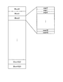
図9は、FATファイルシステムの概要を説明する図である。FATファイルシステムにおけるデータの最小書き込み単位はセクタと呼ばれる。冒頭のセクタには、マスタ・ブート・レコードと呼ばれる情報が格納される。マスタ・ブート・レコードは、パーティション分割の情報(パーティション・エントリ・テーブル)などを含むディスク(本例ではUSBメモリ140やSDカード150などの外部メモリ160)全体の情報である。パーティションとは、ディスクを分割して使用する場合の分割の単位を示す。   FIG. 9 is a diagram for explaining the outline of the FAT file system. The minimum writing unit of data in the FAT file system is called a sector. Information called a master boot record is stored in the first sector. The master boot record is information on the entire disk (in this example, the external memory 160 such as the USB memory 140 and the SD card 150) including partitioning information (partition entry table) and the like. A partition indicates a unit of division when a disk is divided and used.

冒頭のセクタの次のセクタから19個目のセクタまでは空き領域とされ、20個目のセクタからパーティションが始まる。パーティションの先頭セクタはブートセクタであり、ここにBIOSパラメータ・ブロックなどが含まれる。BIOSパラメータ・ブロックには、パーティションのセクタ数や1つのクラスタを構成するセクタ数、1つのFATのセクタ数など、パーティションの内部構成の情報が格納される。クラスタは複数のセクタの集合であり、ユーザデータはクラスタ単位で書き込まれる。   The first sector to the 19th sector are empty, and the partition starts from the 20th sector. The first sector of the partition is a boot sector, which includes a BIOS parameter block and the like. The BIOS parameter block stores information on the internal configuration of the partition, such as the number of sectors in the partition, the number of sectors constituting one cluster, and the number of sectors in one FAT. A cluster is a set of a plurality of sectors, and user data is written in cluster units.

BIOSパラメータ・ブロックを含むブートセクタ以降に、パーティションにおいて通常利用されるデータ領域が設けられる。このデータ領域には、FAT1およびFAT2の2つのFATと、ルート・ディレクトリ・エントリと、実際にユーザデータが書き込まれるユーザデータ領域とが設けられる。   A data area normally used in the partition is provided after the boot sector including the BIOS parameter block. This data area is provided with two FATs, FAT1 and FAT2, a root directory entry, and a user data area into which user data is actually written.

FATは、ユーザデータ領域における各クラスタの状態や次にどのクラスタに繋がるかといった情報を1次元の配列で格納するテーブルである。FAT1とFAT2には同じ値が格納され、一方が他方のミラーとなっている。ユーザデータの書き込みは空きクラスタに対して行われ、ユーザデータの書き込みに応じて、例えばまずFAT2が更新される。そして、ユーザデータの書き込み後、FAT2の内容をFAT1にコピーすることで、ユーザデータの書き込み処理が完了する。   The FAT is a table that stores information such as the state of each cluster in the user data area and the next cluster to be connected in a one-dimensional array. The same value is stored in FAT1 and FAT2, and one is a mirror of the other. User data is written to an empty cluster, and for example, FAT2 is first updated in response to the user data being written. Then, after the user data is written, the contents of FAT2 are copied to FAT1 to complete the user data writing process.

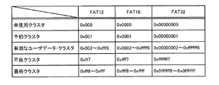
図10は、FAT内のクラスタ識別子を説明する図である。図中のFAT12、FAT16、およびFAT32は、クラスタ識別子の使用ビット数に基づくFATの分類を示している。FATには、ユーザが利用可能なクラスタ(未使用クラスタおよび有効なユーザデータ・クラスタ)とユーザが利用できない予約クラスタ、クラスタの破損を示す不良クラスタ、クラスタ間の繋ぎの最後を示す最終クラスタが用意され、それぞれ図10に示すクラスタ識別子で識別される。   FIG. 10 is a diagram for explaining cluster identifiers in the FAT. FAT12, FAT16, and FAT32 in the figure indicate the classification of FAT based on the number of bits used in the cluster identifier. In FAT, there are a cluster that can be used by the user (unused cluster and valid user data cluster), a reserved cluster that cannot be used by the user, a bad cluster that indicates cluster failure, and a final cluster that indicates the end of the connection between clusters. Each is identified by the cluster identifier shown in FIG.

ルート・ディレクトリ・エントリは、ファイルに関するディレクトリ情報が格納される領域である。ディレクトリ情報には、例えば、ファイル名、ファイル作成日時、ファイル更新日時、属性、データサイズ、データの先頭位置(ファイルの開始クラスタ)などが含まれる。1つのファイルが複数のクラスタに跨る場合、ルート・ディレクトリ・エントリに格納されたディレクトリ情報から開始クラスタが特定され、その開始クラスタに対応したFATのクラスタ番号に格納されたクラスタ識別子から次のクラスタが特定される。以降、後続するクラスタが最終クラスタまでFAT上で順次特定される。   The root directory entry is an area in which directory information regarding files is stored. The directory information includes, for example, a file name, file creation date / time, file update date / time, attribute, data size, data start position (file start cluster), and the like. When one file spans multiple clusters, the start cluster is identified from the directory information stored in the root directory entry, and the next cluster is determined from the cluster identifier stored in the FAT cluster number corresponding to the start cluster. Identified. Thereafter, subsequent clusters are sequentially identified on the FAT up to the final cluster.

FATファイルシステムは、以上の構成によりユーザデータを管理するため、あるファイルに更新を行う場合、次の(1)から(7)に示すような手順を踏むことになる。
(1)ルート・ディレクトリ・エントリからディレクトリ情報を削除
(2)FAT1からクラスタ削除
(3)FAT2からクラスタ削除
(4)ユーザデータ領域にファイル書き込み
(5)FAT2にクラスタ追加
(6)FAT1にクラスタ追加
(7)ルート・ディレクトリ・エントリにディレクトリ情報を追加
Since the FAT file system manages user data with the above configuration, when updating a certain file, the following procedures (1) to (7) are performed.
(1) Delete directory information from root directory entry (2) Delete cluster from FAT1 (3) Delete cluster from FAT2 (4) Write file to user data area (5) Add cluster to FAT2 (6) Add cluster to FAT1 (7) Add directory information to the root directory entry

以上の手順から分かるように、FATファイルシステムでユーザデータを管理する構成では、実際にユーザデータが書き込まれるユーザデータ領域よりも、FATやルート・ディレクトリ・エントリなどの管理情報側の更新頻度が高い。USBメモリ140やSDカード150などの外部メモリ160に対する実際のデータ書き込み時には、例えば、上述のコントローラ110の動作によって実際のアドレスはばらつくように制御される。しかし、その方式にも様々なアルゴリズムがあり、実際にデータの書き込み制御がどのように行われるかユーザ側で把握することは難しい。また、例えば、空きブロックとの交換動作を主として行う場合もあるため、実際にデータが書き込まれる位置が偏る可能性もある。そのため、FATファイルシステムにおける管理情報であるクラスタ単位での書き込み回数の記録は、外部メモリ160の寿命を簡易的に判定するための情報として有効である。   As can be seen from the above procedure, in the configuration in which user data is managed by the FAT file system, the update frequency on the management information side such as FAT and root directory entry is higher than the user data area where user data is actually written. . When actual data is written to the external memory 160 such as the USB memory 140 or the SD card 150, for example, the actual address is controlled to vary depending on the operation of the controller 110 described above. However, there are various algorithms in the method, and it is difficult for the user to grasp how data write control is actually performed. In addition, for example, there is a case where an exchange operation with an empty block is mainly performed, so that a position where data is actually written may be biased. For this reason, recording of the number of writes in cluster units, which is management information in the FAT file system, is effective as information for simply determining the life of the external memory 160.

なお、外部メモリ160に対するデータの書き込みや読み出しは、上述したように、OS上で動作するデバイスドライバにより行われる。本実施形態では、さらに、上位のアプリケーションからファイルアクセスするためのファイルシステムドライバがOS上で動作し、このファイルシステムドライバとデバイスドライバとの協働により、外部メモリ160に対するデータの書き込みや読み出しが行われる。   Note that data is written to and read from the external memory 160 by the device driver operating on the OS as described above. In the present embodiment, a file system driver for accessing a file from a higher-level application operates on the OS, and data is written to and read from the external memory 160 in cooperation with the file system driver and the device driver. Is called.

図11は、本実施形態の寿命管理装置100Bの機能的な構成例を示すブロック図である。本実施形態の寿命管理装置100Bは、例えば図11に示すように、第1の実施形態の寿命管理装置100Aの構成(図3参照)に対して、第2の情報記録部31と、クラスタ管理部32と、第2の書き込み禁止制御部33と、第2の情報書き込み制御部34とが追加された構成とされる。これら寿命管理装置100Bを構成する機能的な構成要素は、上述の第1の実施形態と同様に、例えば、コントローラ110のCPU111が、寿命管理方法の実行手順をプログラムコードとして記述した所定のプログラムを実行することにより実現される。   FIG. 11 is a block diagram illustrating a functional configuration example of the life management apparatus 100B of the present embodiment. For example, as shown in FIG. 11, the life management apparatus 100B of the present embodiment has a second information recording unit 31 and cluster management for the configuration of the life management apparatus 100A of the first embodiment (see FIG. 3). The unit 32, the second write prohibition control unit 33, and the second information write control unit 34 are added. As in the first embodiment, the functional components constituting the life management apparatus 100B include, for example, a predetermined program in which the CPU 111 of the controller 110 describes the execution procedure of the life management method as a program code. It is realized by executing.

第2の情報記録部31は、FATファイルシステムで管理されるクラスタごとの書き込み回数を、外部メモリ160の利用開始日時と対応付けて、揮発性の内部メモリであるDRAM112に記録する機能モジュールである。外部メモリ160の利用開始日時と対応付けて記録されるクラスタごとの書き込み回数の情報を、以下では「書き込み回数管理情報」と呼ぶ。   The second information recording unit 31 is a functional module that records the number of writes for each cluster managed by the FAT file system in the DRAM 112, which is a volatile internal memory, in association with the use start date and time of the external memory 160. . The information on the number of times of writing for each cluster recorded in association with the use start date and time of the external memory 160 is hereinafter referred to as “write number management information”.

第2の情報記録部31は、画像形成装置100の電源投入時に、画像形成装置100に接続されている外部メモリ160に書き込み回数管理情報が格納されているか否かを確認する。そして、外部メモリ160に書き込み管理情報が格納されていれば、第2の情報記録部31は、その書き込み管理情報を外部メモリ160から読み出してDRAM112にコピーし、その後、外部メモリ160に対するデータの書き込みが行われるたびに、クラスタごとの書き込み回数を計測してDRAM112上の書き込み管理情報を更新する。一方、画像形成装置100に対して新規の外部メモリ160が接続された場合など、外部メモリ160に書き込み管理情報が格納されていなければ、第2の情報記録部31は、例えば、現在時刻を外部メモリ160の利用開始日時としてDRAM112に記録し、その後、外部メモリ160に対するデータの書き込みが行われるたびに、クラスタごとの書き込み回数を計測してDRAM112に記録する。   The second information recording unit 31 checks whether or not the write count management information is stored in the external memory 160 connected to the image forming apparatus 100 when the image forming apparatus 100 is turned on. If the write management information is stored in the external memory 160, the second information recording unit 31 reads the write management information from the external memory 160, copies it to the DRAM 112, and then writes data to the external memory 160. Is performed, the write management information on the DRAM 112 is updated by measuring the number of writes for each cluster. On the other hand, if the write management information is not stored in the external memory 160, such as when a new external memory 160 is connected to the image forming apparatus 100, the second information recording unit 31 sets, for example, the current time to the external The start date and time of use of the memory 160 is recorded in the DRAM 112. Thereafter, each time data is written to the external memory 160, the number of times of writing for each cluster is measured and recorded in the DRAM 112.

図12は、書き込み回数管理情報40の一例を示す図である。書き込み回数管理情報40は、図12に示すように、外部メモリ160の利用開始日時を示す情報41と対応付けて、クラスタ番号ごとの書き込み回数を示す情報42が記録された構成である。FAT上、実際のユーザデータが書き込まれるクラスタは、クラスタ番号が「2」以降のクラスタとなる。そこで、例えば、クラスタ番号「0」とクラスタ番号「1」とを便宜上、FATやルート・ディレクトリ・エントリなどの管理情報に対応するクラスタ番号として割り当てることで、管理情報に対する更新を行った際の書き込み回数をクラスタごとの書き込み回数として記録することができる。   FIG. 12 is a diagram illustrating an example of the write count management information 40. As shown in FIG. 12, the write count management information 40 has a configuration in which information 42 indicating the write count for each cluster number is recorded in association with information 41 indicating the use start date and time of the external memory 160. On the FAT, clusters to which actual user data is written are clusters having cluster numbers “2” and later. Therefore, for example, the cluster number “0” and the cluster number “1” are assigned as cluster numbers corresponding to management information such as FAT and root directory entry for the sake of convenience. The number of times can be recorded as the number of times of writing for each cluster.

クラスタ管理部32は、第2の情報記録部31によりDRAM112に記録された書き込み回数管理情報40において書き込み回数が所定回数に達したクラスタ、つまり、外部メモリ160において書き込み回数が所定回数に達したクラスタを不良クラスタに設定する機能モジュールである。このクラスタ管理部32による処理は、例えば、書き込み回数が所定回数に達したクラスタに対応するFAT上のクラスタに、不良クラスタを示すクラスタ識別子を格納することで実現できる。   The cluster management unit 32 is a cluster in which the number of writes reaches a predetermined number in the write number management information 40 recorded in the DRAM 112 by the second information recording unit 31, that is, a cluster in which the number of writes reaches the predetermined number in the external memory 160. Is a functional module for setting a bad cluster. The processing by the cluster management unit 32 can be realized, for example, by storing a cluster identifier indicating a defective cluster in a cluster on the FAT corresponding to the cluster that has been written a predetermined number of times.

第2の書き込み禁止制御部33は、不良クラスタの数が所定数を超えた外部メモリ160に対する書き込みを禁止するように制御する機能モジュールである。第2の書き込み禁止制御部33は、例えば、FATを参照して不良クラスタの数をカウントし、不良クラスタの数が所定数に達した場合に外部メモリ160を書き込み禁止モードに設定することにより、この外部メモリ160に対する書き込みを禁止することができる。なお、書き込み禁止モードの設定は、例えば、外部メモリ160に設けられた所定のスイッチをオンすることで実現してもよいし、予め定めた所定のフラグをオンすることで実現してもよい。また、外部メモリ160に対応するデバイスドライバの設定を書き込み禁止モードとすることで、外部メモリ160に対する書き込みを禁止するように制御してもよい。   The second write prohibition control unit 33 is a functional module that controls to prohibit writing to the external memory 160 in which the number of defective clusters exceeds a predetermined number. For example, the second write prohibition control unit 33 refers to the FAT to count the number of defective clusters, and when the number of defective clusters reaches a predetermined number, by setting the external memory 160 in the write prohibit mode, Writing to the external memory 160 can be prohibited. The setting of the write prohibition mode may be realized by turning on a predetermined switch provided in the external memory 160, or may be realized by turning on a predetermined flag. Further, the setting of the device driver corresponding to the external memory 160 may be controlled to be prohibited from writing to the external memory 160 by setting the device driver to the write prohibiting mode.

第2の情報書き込み制御部34は、画像形成装置100の電源遮断時に、揮発性の内部メモリであるDRAM112に記録されている書き込み回数管理情報40を、外部メモリ160に書き込むように制御する機能モジュールである。画像形成装置100の電源が遮断されるたびに第2の情報書き込み制御部34がDRAM112上の書き込み回数管理情報40を外部メモリ160に書き込むように制御することで、画像形成装置100と外部メモリ160との間で書き込み回数管理情報40の同期が図られる。なお、第2の情報書き込み制御部34は、画像形成装置100の電源遮断時だけでなく、画像形成装置100が省エネ運転モードへ移行するときにも、DRAM112に記録されている書き込み回数管理情報40を外部メモリ160に書き込むように制御してもよい。これにより、データ同期の頻度を高めることができる。   The second information write control unit 34 controls to write the write count management information 40 recorded in the DRAM 112, which is a volatile internal memory, to the external memory 160 when the image forming apparatus 100 is powered off. It is. The second information writing control unit 34 performs control so that the write count management information 40 on the DRAM 112 is written in the external memory 160 each time the power of the image forming apparatus 100 is turned off. The write count management information 40 is synchronized with the. Note that the second information writing control unit 34 is not only when the power of the image forming apparatus 100 is shut off, but also when the image forming apparatus 100 shifts to the energy saving operation mode. May be controlled to be written in the external memory 160. Thereby, the frequency of data synchronization can be increased.

図13は、外部メモリ160に書き込み回数管理情報40を書き込む方法の一例を説明する図である。画像形成装置100に対して外部メモリ160が接続されると、まず、図13に示すように、FAT上で所定の未使用クラスタに特別なフラグ(ここでは最終クラスタを意味する0x0ffffff8を利用するものとする)を立てることで、このクラスタを書き込み回数管理用クラスタに設定し、他の目的での利用ができないようにしておく。そして、外部メモリ160に書き込み回数管理情報40を書き込む際には、FAT上で上記のフラグを立てたクラスタ番号に対応するユーザデータ領域内の書き込み回数管理用クラスタに、図12に示したような書き込み回数管理情報40を書き込む。   FIG. 13 is a diagram for explaining an example of a method for writing the write count management information 40 to the external memory 160. When the external memory 160 is connected to the image forming apparatus 100, first, as shown in FIG. 13, a special flag (here, 0x0ffffff8 meaning the final cluster) is used for a predetermined unused cluster on the FAT. This cluster is set as a write count management cluster so that it cannot be used for other purposes. When the write count management information 40 is written to the external memory 160, the write count management cluster in the user data area corresponding to the cluster number for which the above flag is set on the FAT is set as shown in FIG. Write write count management information 40 is written.

本実施形態の寿命管理装置100Bでは、寿命予測部14が、上述した第1の実施形態の寿命管理装置100Aと同様に、NVRAM115に記録された外部メモリ160の積算書き込み量と利用開始日時とに基づいて、外部メモリ160の積算書き込み量が所定量に達する寿命到達日時を予測できることに加えて、DRAM112に記録された書き込み回数管理情報40に基づいて、外部メモリ160の総書き込み回数が上限回数に達する寿命到達日時を予測することもできる。   In the life management apparatus 100B of the present embodiment, the life prediction unit 14 uses the accumulated write amount of the external memory 160 recorded in the NVRAM 115 and the use start date and time as in the life management apparatus 100A of the first embodiment described above. Based on the write count management information 40 recorded in the DRAM 112, the total number of writes in the external memory 160 can be set to the upper limit count in addition to predicting the life end date and time when the accumulated write amount in the external memory 160 reaches a predetermined amount. It is also possible to predict the life reaching date and time.

外部メモリ160の総書き込み回数が所定回数に達する寿命到達日時を予測する場合、寿命予測部14は、上述の寿命到達日時を予測するタイミングになると、DRAM112に記録された書き込み回数管理情報40を参照し、まず、外部メモリ160の利用開始日時と現在時刻とに基づいて、外部メモリ160の利用を開始してからの経過時間を算出する。そして、書き込み回数管理情報40に含まれるクラスタごとの書き込み回数の総和(総書き込み回数)を経過時間で除算することにより、外部メモリ160に対する単位時間(例えば1時間)あたりの平均書き込み回数を算出する。次に、寿命予測部14は、書き込み回数管理情報40に含まれるクラスタごとの書き込み回数の総和と所定回数との差分を単位時間あたりの平均書き込み回数で除算することにより、外部メモリ160の総書き込み回数が上限回数に達する寿命到達日時を予測する。   When predicting the life reaching date and time when the total number of writes in the external memory 160 reaches the predetermined number of times, the life predicting unit 14 refers to the writing count management information 40 recorded in the DRAM 112 at the timing for predicting the above life reaching date and time. First, based on the use start date and time and the current time of the external memory 160, the elapsed time from the start of use of the external memory 160 is calculated. Then, the average number of writes per unit time (for example, one hour) to the external memory 160 is calculated by dividing the total number of writes (total number of writes) for each cluster included in the write count management information 40 by the elapsed time. . Next, the life predicting unit 14 divides the difference between the total number of writes for each cluster included in the write count management information 40 and the predetermined number by the average number of writes per unit time, thereby total write in the external memory 160. Predict the date and time when the life reaches the upper limit.

次に、本実施形態の寿命管理装置100Bの動作のうち、第1の実施形態の寿命管理装置100Aとは異なる動作について、図14乃至図17を参照して説明する。   Next, of the operations of the life management apparatus 100B of this embodiment, operations different from the life management apparatus 100A of the first embodiment will be described with reference to FIGS.

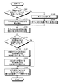
図14は、画像形成装置100に対して外部メモリ160が接続されたときの寿命管理装置100Bの動作例を示すフローチャートである。この図14のフローチャートで示す一連の処理は、画像形成装置100に対して外部メモリ160が接続されたことが検知されるたびに実行される。   FIG. 14 is a flowchart illustrating an operation example of the life management apparatus 100B when the external memory 160 is connected to the image forming apparatus 100. A series of processes shown in the flowchart of FIG. 14 is executed every time it is detected that the external memory 160 is connected to the image forming apparatus 100.

画像形成装置100に対して外部メモリ160が接続されたことが検知されると、まず、第2の情報書き込み制御部34により、画像形成装置100に接続された外部メモリ160に書き込み回数管理用クラスタがあるか否かが判定される(ステップS501)。そして、外部メモリ160に書き込み回数管理用クラスタがなければ(ステップS501:No)、第2の情報書き込み制御部34は、外部メモリ160のFATを参照して未使用クラスタを探し、未使用クラスタを書き込み回数管理用クラスタに設定する(ステップS502)。次に、第2の情報書き込み制御部34は、ステップS502で設定した外部メモリ160の書き込み回数管理用クラスタに対して、現在時刻を利用開始日時として書き込む(ステップS503)。この情報が、書き込み回数管理情報40の初期情報となる。   When it is detected that the external memory 160 is connected to the image forming apparatus 100, first, the second information writing control unit 34 writes the write count management cluster to the external memory 160 connected to the image forming apparatus 100. It is determined whether or not there is (step S501). If there is no write count management cluster in the external memory 160 (step S501: No), the second information write control unit 34 refers to the FAT in the external memory 160 to search for an unused cluster, and finds an unused cluster. It is set in the write count management cluster (step S502). Next, the second information write control unit 34 writes the current time as the use start date and time in the write count management cluster in the external memory 160 set in step S502 (step S503). This information is the initial information of the write count management information 40.

その後、第2の情報記録部31が、外部メモリ160の書き込み回数管理用クラスタの書き込み回数管理情報40をDRAM112にコピーし(ステップS504)、一連の処理が終了する。また、ステップS501において外部メモリ160に書き込み回数管理用クラスタがあると判定された場合は(ステップS501:Yes)、第2の情報記録部31がその書き込み回数管理用クラスタの書き込み回数管理情報40をDRAM112にコピーし(ステップS504)、一連の処理が終了する。   Thereafter, the second information recording unit 31 copies the write count management information 40 of the write count management cluster in the external memory 160 to the DRAM 112 (step S504), and the series of processing ends. If it is determined in step S501 that the external memory 160 has a write count management cluster (step S501: Yes), the second information recording unit 31 stores the write count management information 40 of the write count management cluster. Copying to the DRAM 112 (step S504), a series of processing ends.

図15は、外部メモリ160に対する書き込み時における寿命管理装置100Bの動作例を示すフローチャートである。この図15のフローチャートで示す一連の処理は、書き込み管理モードで動作するデバイスドライバが書き込み命令を受けるたびに実行される。   FIG. 15 is a flowchart illustrating an operation example of the life management apparatus 100B when writing to the external memory 160. The series of processing shown in the flowchart of FIG. 15 is executed every time a device driver operating in the write management mode receives a write command.

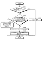
外部メモリ160に対応するデバイスドライバが書き込み命令を受けた場合、まず、外部メモリ160が書き込み禁止モードになっているか否かが、表示制御部15によって判定される(ステップS601)。そして、外部メモリ160が書き込み禁止モードになっている場合(ステップS601:Yes)、表示制御部15が、外部メモリ160が利用できないことを示すエラーメッセージなどをオペレーションパネル120に表示させ(ステップ602)、一連の処理が終了する。   When the device driver corresponding to the external memory 160 receives a write command, first, the display control unit 15 determines whether or not the external memory 160 is in the write inhibit mode (step S601). If the external memory 160 is in the write prohibit mode (step S601: Yes), the display control unit 15 causes the operation panel 120 to display an error message indicating that the external memory 160 cannot be used (step 602). The series of processing ends.

一方、外部メモリ160が書き込み禁止モードになっていなければ(ステップS601:No)、クラスタ管理部32が、DRAM112に記録されている書き込み回数管理情報40を参照し、書き込み対象のクラスタ番号に対応する書き込み回数が所定回数に達しているか否かを判定する(ステップS603)。そして、書き込み対象のクラスタ番号に対応する書き込み回数が所定回数に達していれば(ステップS603:Yes)、外部メモリ160の当該クラスタを不良クラスタに設定し(ステップS604)、一連の処理が終了する。   On the other hand, if the external memory 160 is not in the write inhibit mode (step S601: No), the cluster management unit 32 refers to the write count management information 40 recorded in the DRAM 112 and corresponds to the cluster number to be written. It is determined whether the number of writings has reached a predetermined number (step S603). If the number of writes corresponding to the cluster number to be written has reached a predetermined number (step S603: Yes), the cluster in the external memory 160 is set as a defective cluster (step S604), and a series of processing ends. .

一方、書き込み対象のクラスタ番号に対応する書き込み回数が所定回数に達していなければ(ステップS603:No)、デバイスドライバによって、外部メモリ160の当該クラスタに対してデータの書き込みが行われる(ステップS605)。そして、第2の情報記録部31が、当該クラスタに対応する書き込み回数が増加するように、DRAM112の書き込み回数管理情報40を更新し(ステップS606)、一連の処理が終了する。   On the other hand, if the number of writes corresponding to the cluster number to be written has not reached the predetermined number (step S603: No), the device driver writes data to the cluster in the external memory 160 (step S605). . Then, the second information recording unit 31 updates the write count management information 40 of the DRAM 112 so that the write count corresponding to the cluster increases (step S606), and the series of processing ends.

図16は、寿命到達日時を予測するタイミングになったときの寿命管理装置100Bの動作例を示すフローチャートである。この図16のフローチャートで示す一連の処理は、寿命到達日時を予測するタイミングとして予め定められた所定のタイミングになるたびに実行される。   FIG. 16 is a flowchart showing an operation example of the life management apparatus 100B when it is time to predict the life arrival date and time. The series of processes shown in the flowchart of FIG. 16 is executed every time a predetermined timing is set as a timing for predicting the life arrival date and time.

寿命到達日時を予測するタイミングになると、まず、画像形成装置100に接続されている外部メモリ160のFATが参照され、不良クラスタの数が所定数を超えているか否かが判定される(ステップS701)。そして、不良クラスタの数が所定数を超えていれば(ステップS701:Yes)、表示制御部15が、外部メモリ160が利用できないことを示すエラーメッセージなどをオペレーションパネル120に表示させる(ステップS702)。また、第2の書き込み禁止制御部33が、外部メモリ160を書き込み禁止モードに設定し(ステップS703)、一連の処理が終了する。   When it is time to predict the life arrival date and time, first, the FAT of the external memory 160 connected to the image forming apparatus 100 is referred to, and it is determined whether or not the number of defective clusters exceeds a predetermined number (step S701). ). If the number of defective clusters exceeds the predetermined number (step S701: Yes), the display control unit 15 causes the operation panel 120 to display an error message indicating that the external memory 160 cannot be used (step S702). . In addition, the second write prohibition control unit 33 sets the external memory 160 to the write prohibition mode (step S703), and the series of processing ends.

一方、不良クラスタの数が所定数を超えていなければ(ステップS701:No)、寿命予測部14は、DRAM112の書き込み回数管理情報40を参照し、外部メモリ160の利用開始日時と現在時刻と外部メモリ160の総書き込み回数(クラスタごとの書き込み回数の総和)とに基づいて、外部メモリ160に対する単位時間あたりの平均書き込み回数を算出する(ステップS704)。そして、寿命予測部14は、積算書き込み回数と上限回数との差分を、ステップS704で算出した単位時間あたりの平均書き込み回数で除算することにより、外部メモリ160の総書き込み回数が上限回数に達する寿命到達日時を予測する(ステップS705)。   On the other hand, if the number of defective clusters does not exceed the predetermined number (step S701: No), the lifetime predicting unit 14 refers to the write count management information 40 of the DRAM 112, and starts using the current date and time and the external time of the external memory 160. Based on the total number of times of writing in the memory 160 (the total number of times of writing for each cluster), the average number of times of writing to the external memory 160 per unit time is calculated (step S704). Then, the lifetime predicting unit 14 divides the difference between the cumulative number of writes and the upper limit number by the average number of writes per unit time calculated in step S704, so that the total number of writes in the external memory 160 reaches the upper limit number. The arrival date and time is predicted (step S705).

次に、表示制御部15が、ステップS705で予測された外部メモリ160の寿命到達日時をオペレーションパネル120に表示させる(ステップS706)。また、表示制御部15は、ステップS705で予測された外部メモリ160の寿命到達日時が現在から所定期間内(例えば3か月以内)の日時かどうかを判定し(ステップS707)、外部メモリ160の寿命到達日時が所定期間内であれば(ステップS707:Yes)、外部メモリ160の寿命が近い旨の警告メッセージをオペレーションパネル120に表示させて(ステップS708)、一連の処理が終了する。なお、外部メモリ160の寿命到達日時が所定期間内でなければ(ステップS707:No)、ステップS706の寿命到達日時の表示のみが行われる。   Next, the display control unit 15 causes the operation panel 120 to display the life reaching date / time of the external memory 160 predicted in Step S705 (Step S706). Further, the display control unit 15 determines whether or not the life reaching date / time of the external memory 160 predicted in step S705 is a date / time within a predetermined period (for example, within 3 months) from the current time (step S707). If the life arrival date / time is within the predetermined period (step S707: Yes), a warning message indicating that the external memory 160 is near the end of life is displayed on the operation panel 120 (step S708), and the series of processing ends. If the life reaching date / time of the external memory 160 is not within the predetermined period (step S707: No), only the life reaching date / time is displayed in step S706.

図17は、画像形成装置100の電源遮断時における寿命管理装置100Bの動作例を示すフローチャートである。この図17のフローチャートで示す一連の処理は、画像形成装置100の電源を遮断する操作が行われるたびに実行される。   FIG. 17 is a flowchart illustrating an operation example of the life management apparatus 100B when the image forming apparatus 100 is powered off. A series of processes shown in the flowchart of FIG. 17 is executed every time an operation for shutting off the power supply of the image forming apparatus 100 is performed.

画像形成装置100の電源を遮断する操作が行われると、まず、デバイスドライバにより、外部メモリ160のアンマウント処理が開始される(ステップS801)。その後、第2の情報書き込み制御部34が、DRAM112に記録されている書き込み回数管理情報40を外部メモリ160の書き込み回数管理クラスタにコピーし(ステップS802)、画像形成装置100と外部メモリ160との間で書き込み回数管理情報40を同期させて、一連の処理が終了する。   When an operation for shutting off the power supply of the image forming apparatus 100 is performed, first, the device driver starts an unmount process of the external memory 160 (step S801). Thereafter, the second information write control unit 34 copies the write count management information 40 recorded in the DRAM 112 to the write count management cluster of the external memory 160 (step S802), and the image forming apparatus 100 and the external memory 160 communicate with each other. The write count management information 40 is synchronized with each other, and a series of processing ends.

以上、具体的な例を挙げながら詳細に説明したように、本実施形態の寿命管理装置100Bによれば、第2の情報記録部31が、外部メモリ160のクラスタごとの書き込み回数を外部メモリ160の利用開始日時と対応付けて書き込み回数管理情報40としてDRAM112に記録する。そして、クラスタ管理部32が、書き込み回数が所定回数に達したクラスタを不良クラスタに設定し、不良クラスタの数が所定数を超えると外部メモリ160が寿命に達したと判断して、第2の書き込み禁止制御部33が、外部メモリ160に対する書き込みを禁止するように制御する。したがって、本実施形態の寿命管理装置100Bによれば、特定のクラスタに対するデータの書き込みが集中した場合であっても外部メモリ160の寿命を正しく判断し、寿命に達した外部メモリ160に対してデータの書き込みを行うことにより外部メモリ160が記憶するデータを消失させてしまう不都合を有効に抑制することができる。   As described above in detail with specific examples, according to the life management apparatus 100B of the present embodiment, the second information recording unit 31 sets the number of writes for each cluster in the external memory 160 to the external memory 160. Is recorded in the DRAM 112 as the write count management information 40 in association with the use start date and time. Then, the cluster management unit 32 sets the cluster that has reached the predetermined number of times of writing as a defective cluster, and determines that the external memory 160 has reached the end of its life when the number of defective clusters exceeds the predetermined number. The write prohibition control unit 33 controls to prohibit writing to the external memory 160. Therefore, according to the lifetime management apparatus 100B of this embodiment, even when data writing to a specific cluster is concentrated, the lifetime of the external memory 160 is correctly determined, and data is stored in the external memory 160 that has reached the lifetime. Thus, the disadvantage that the data stored in the external memory 160 is lost can be effectively suppressed.

また、本実施形態の寿命管理装置100Bによれば、寿命予測部14が、DRAM112に記録された書き込み回数管理情報40に基づいて、外部メモリ160の寿命到達日時、具体的には、外部メモリ160の総書き込み回数が上限回数に達する寿命到達日時を予測できるように構成されているので、外部メモリ160の寿命を適切に管理することができる。   Further, according to the life management apparatus 100B of the present embodiment, the life prediction unit 14 determines the life arrival date / time of the external memory 160, specifically, the external memory 160 based on the write count management information 40 recorded in the DRAM 112. Since the lifetime reaching date and time when the total number of times of writing reaches the upper limit number can be predicted, the lifetime of the external memory 160 can be appropriately managed.

また、本実施形態の寿命管理装置100Bによれば、画像形成装置100の電源遮断時に、第2の情報書き込み制御部34が、DRAM112に記録された書き込み回数管理情報40を外部メモリ160に書き込むように制御するので、画像形成装置100と外部メモリ160との間で書き込み回数管理情報40を同期させて、外部メモリ160のクラスタごとの書き込み回数を適切に管理することができる。   Further, according to the life management apparatus 100B of the present embodiment, the second information write control unit 34 writes the write count management information 40 recorded in the DRAM 112 to the external memory 160 when the image forming apparatus 100 is powered off. Therefore, the write count management information 40 can be synchronized between the image forming apparatus 100 and the external memory 160, and the write count for each cluster of the external memory 160 can be appropriately managed.

なお、上述の例では、画像形成装置100のコントローラ110内に設けられた揮発性のメモリであるDRAM112に書き込み回数管理情報40を記録する構成としているが、本実施形態の寿命管理装置100Bは、画像形成装置100のコントローラ110内に設けられたNVRAM115などの不揮発性メモリ、あるいは、コントローラ110に接続されたHDD(ハードディスクドライブ)などに書き込み回数管理情報40を記録する構成としてもよい。このような構成とした場合は、画像形成装置100の予期せぬ電源遮断(例えば停電など)により書き込み回数管理情報40が消失する不都合を有効に防止することができる。   In the above example, the write count management information 40 is recorded in the DRAM 112, which is a volatile memory provided in the controller 110 of the image forming apparatus 100. However, the life management apparatus 100B of the present embodiment is configured as follows. The write count management information 40 may be recorded in a nonvolatile memory such as the NVRAM 115 provided in the controller 110 of the image forming apparatus 100 or an HDD (hard disk drive) connected to the controller 110. With such a configuration, it is possible to effectively prevent a problem that the write count management information 40 is lost due to an unexpected power shutdown (for example, a power failure) of the image forming apparatus 100.

以上、本発明の具体的な実施形態について説明したが、上述した実施形態は本発明の一適用例を示したものである。本発明は、上述した実施形態そのままに限定されるものではなく、実施段階ではその要旨を逸脱しない範囲で様々な変形や変更を加えて具体化することができる。   Although specific embodiments of the present invention have been described above, the above-described embodiments show an application example of the present invention. The present invention is not limited to the above-described embodiment as it is, and can be embodied with various modifications and changes without departing from the scope of the invention in the implementation stage.

11 識別情報取得部
12 積算書き込み量算出部
13 情報記録部
14 寿命予測部
15 表示制御部
16 書き込み禁止制御部
17 情報書き込み制御部
31 第2の情報記録部
32 クラスタ管理部
33 第2の書き込み禁止制御部
34 第2の情報書き込み制御部
40 書き込み回数管理情報
100 画像形成装置
100A,100B 寿命管理装置
110 コントローラ
112 DRAM
115 NVRAM
140 USBメモリ
150 SDカード
160 外部メモリ
DESCRIPTION OF SYMBOLS 11 Identification information acquisition part 12 Integrated writing amount calculation part 13 Information recording part 14 Life prediction part 15 Display control part 16 Write prohibition control part 17 Information write control part 31 2nd information recording part 32 Cluster management part 33 2nd write prohibition Control unit 34 Second information write control unit 40 Write count management information 100 Image forming apparatus 100A, 100B Life management apparatus 110 Controller 112 DRAM
115 NVRAM
140 USB memory 150 SD card 160 External memory

特開2012−088937号公報JP 2012-088937 A

Claims (12)

第1の記憶装置に対して書き込みを行うたびに前記第1の記憶装置に対する積算書き込み量を算出する積算書き込み量算出部と、
前記積算書き込み量を、前記第1の記憶装置の識別情報および前記第1の記憶装置の利用開始日時と対応付けて第2の記憶装置に記録する第1の情報記録部と、
前記第2の記憶装置に記録された前記積算書き込み量および前記利用開始日時に基づいて、前記第1の記憶装置の寿命到達日時を予測する寿命予測部と、
を備える寿命管理装置。
An integrated write amount calculating unit that calculates an integrated write amount for the first storage device each time writing to the first storage device;
A first information recording unit that records the accumulated writing amount in a second storage device in association with the identification information of the first storage device and the use start date and time of the first storage device;
A life prediction unit for predicting the life arrival date and time of the first storage device based on the accumulated writing amount and the use start date and time recorded in the second storage device;
A life management device comprising:
前記第1の記憶装置が前記識別情報を保持する場合は該識別情報を読み取り、前記第1の記憶装置が前記識別情報を保持していない場合は、前記識別情報を生成するとともに、生成した前記識別情報を前記第1の記憶装置に書き込む識別情報取得部をさらに備える、
請求項1に記載の寿命管理装置。
When the first storage device holds the identification information, the identification information is read. When the first storage device does not hold the identification information, the identification information is generated and the generated An identification information acquisition unit for writing identification information to the first storage device;
The life management apparatus according to claim 1.
前記積算書き込み量が所定量に達した前記第1の記憶装置に対する書き込みを禁止するように制御する第1の書き込み禁止制御部をさらに備える、
請求項1または2に記載の寿命管理装置。
A first write prohibition control unit that controls to prohibit writing to the first storage device in which the cumulative write amount reaches a predetermined amount;
The life management apparatus according to claim 1 or 2.
所定の操作に応じて、前記第2の記憶装置に記録された前記積算書き込み量および前記利用開始日時を前記第1の記憶装置に書き込むように制御する第1の情報書き込み制御部をさらに備える、
請求項1乃至3のいずれか一項に記載の寿命管理装置。
In accordance with a predetermined operation, the information processing apparatus further includes a first information writing control unit that controls to write the accumulated writing amount and the use start date and time recorded in the second storage device to the first storage device.
The life management apparatus as described in any one of Claims 1 thru | or 3.
前記寿命到達日時を表示装置に表示させるように制御する表示制御部をさらに備える、
請求項1乃至4のいずれか一項に記載の寿命管理装置。
A display control unit for controlling to display the life attainment date and time on a display device;
The lifetime management apparatus as described in any one of Claims 1 thru | or 4.
前記第1の記憶装置は、機器に対して外付けで接続されるフラッシュメモリであり、
前記第2の記憶装置は、前記機器に実装された書き換え回数制限のない不揮発性メモリである、
請求項1乃至5のいずれか一項に記載の寿命管理装置。
The first storage device is a flash memory connected externally to a device,
The second storage device is a non-volatile memory that is implemented in the device and has no rewrite limit.
The lifetime management apparatus as described in any one of Claims 1 thru | or 5.
前記第1の記憶装置に対応するファイルシステムで管理されるクラスタごとの書き込み回数を前記第1の記憶装置の利用開始日時と対応付けて第3の記憶装置に記録する第2の情報記録部と、
前記第3の記憶装置に記録された書き込み回数が所定回数に達したクラスタを不良クラスタに設定するクラスタ管理部と、
前記不良クラスタの数が所定数を超えた前記第1の記憶装置に対する書き込みを禁止するように制御する第2の書き込み禁止制御部と、をさらに備える、
請求項1乃至6のいずれか一項に記載の寿命管理装置。
A second information recording unit that records the number of writes for each cluster managed by the file system corresponding to the first storage device in a third storage device in association with the use start date and time of the first storage device; ,
A cluster management unit that sets a cluster in which the number of writes recorded in the third storage device reaches a predetermined number of times as a defective cluster;
A second write prohibition control unit that controls to prohibit writing to the first storage device in which the number of defective clusters exceeds a predetermined number;
The lifetime management apparatus as described in any one of Claims 1 thru | or 6.
前記寿命予測部は、前記第2の記憶装置に記録された前記積算書き込み量および前記利用開始日時、または、前記第3の記憶装置に記録されたクラスタごとの書き込み回数の総和および前記利用開始日時に基づいて、前記第1の記憶装置の寿命到達日時を予測する、
請求項7に記載の寿命管理装置。
The life prediction unit includes the integrated writing amount and the use start date / time recorded in the second storage device, or the sum of the number of writes for each cluster recorded in the third storage device and the use start date / time. Based on the above, a life reaching date / time of the first storage device is predicted,
The life management apparatus according to claim 7.
前記第1の記憶装置は、機器に対して外付けで接続されるフラッシュメモリであり、
前記第3の記憶装置は、前記機器に実装された揮発性メモリである、
請求項7または8に記載の寿命管理装置。
The first storage device is a flash memory connected externally to a device,
The third storage device is a volatile memory mounted on the device.
The life management apparatus according to claim 7 or 8.
前記機器の電源遮断時または省エネ運転モードへの移行時に、前記第3の記憶装置に記録されたクラスタごとの書き込み回数を前記第1の記憶装置に書き込むように制御する第2の情報書き込み制御部をさらに備える、
請求項9に記載の寿命管理装置。
A second information writing control unit that controls the number of times of writing for each cluster recorded in the third storage device to be written in the first storage device when the device is powered off or shifted to the energy saving operation mode. Further comprising
The life management apparatus according to claim 9.
前記第1の記憶装置は、機器に対して外付けで接続されるフラッシュメモリであり、
前記第3の記憶装置は、前記機器に実装された書き換え回数制限のない不揮発性メモリである、
請求項7または8に記載の寿命管理装置。
The first storage device is a flash memory connected externally to a device,
The third storage device is a non-volatile memory that is mounted on the device and has no rewrite frequency limit.
The life management apparatus according to claim 7 or 8.
第1の記憶装置に対して書き込みを行うたびに前記第1の記憶装置に対する積算書き込み量を算出するステップと、
前記積算書き込み量を、前記第1の記憶装置の識別情報および前記第1の記憶装置の利用開始日時と対応付けて第2の記憶装置に記録するステップと、
前記第2の記憶装置に記録された前記積算書き込み量および前記利用開始日時に基づいて、前記第1の記憶装置の寿命到達日時を予測するステップと、を含む寿命管理方法。
Calculating an integrated write amount for the first storage device each time writing to the first storage device;
Recording the accumulated write amount in a second storage device in association with the identification information of the first storage device and the use start date and time of the first storage device;
A service life management method comprising: predicting a service life arrival date and time of the first storage device based on the accumulated write amount recorded in the second storage device and the use start date and time.
JP2016226547A 2016-02-10 2016-11-22 Life management device and life management method Pending JP2017142776A (en)

Priority Applications (1)

Application Number Priority Date Filing Date Title
US15/427,441 US10222982B2 (en) 2016-02-10 2017-02-08 Lifetime management device and lifetime management method

Applications Claiming Priority (2)

Application Number Priority Date Filing Date Title
JP2016023778 2016-02-10

Publications (1)

Publication Number Publication Date
JP2017142776A true JP2017142776A (en) 2017-08-17

Family

ID=59628586

Family Applications (1)

Application Number Title Priority Date Filing Date
JP2016226547A Pending JP2017142776A (en) 2016-02-10 2016-11-22 Life management device and life management method

Country Status (1)

Country Link
JP (1) JP2017142776A (en)

Cited By (5)

* Cited by examiner, † Cited by third party
Publication number Priority date Publication date Assignee Title
JP2019128834A (en) * 2018-01-25 2019-08-01 株式会社リコー Information processing apparatus, information processing method, and program
JP2019144816A (en) * 2018-02-20 2019-08-29 京セラドキュメントソリューションズ株式会社 Information processing device and information processing method
WO2020161981A1 (en) * 2019-02-06 2020-08-13 ソニー株式会社 Memory diagnosis device and memory diagnosis method
JP2020154674A (en) * 2019-03-20 2020-09-24 株式会社リコー Information processing device, information processing method, and program
WO2021048890A1 (en) * 2019-09-09 2021-03-18 三菱電機株式会社 Data storage control device and data storage control method

Cited By (9)

* Cited by examiner, † Cited by third party
Publication number Priority date Publication date Assignee Title
JP2019128834A (en) * 2018-01-25 2019-08-01 株式会社リコー Information processing apparatus, information processing method, and program
JP7031327B2 (en) 2018-01-25 2022-03-08 株式会社リコー Information processing equipment, information processing methods, and programs
JP2019144816A (en) * 2018-02-20 2019-08-29 京セラドキュメントソリューションズ株式会社 Information processing device and information processing method
WO2020161981A1 (en) * 2019-02-06 2020-08-13 ソニー株式会社 Memory diagnosis device and memory diagnosis method
JPWO2020161981A1 (en) * 2019-02-06 2021-12-02 ソニーグループ株式会社 Memory diagnostic device and memory diagnostic method
JP7424321B2 (en) 2019-02-06 2024-01-30 ソニーグループ株式会社 Memory diagnostic device and memory diagnostic method
JP2020154674A (en) * 2019-03-20 2020-09-24 株式会社リコー Information processing device, information processing method, and program
JP7225981B2 (en) 2019-03-20 2023-02-21 株式会社リコー Information processing device, information processing method, and program
WO2021048890A1 (en) * 2019-09-09 2021-03-18 三菱電機株式会社 Data storage control device and data storage control method

Similar Documents

Publication Publication Date Title
US10222982B2 (en) Lifetime management device and lifetime management method
TWI597605B (en) Method of wear leveling for data storage device
JP2017142776A (en) Life management device and life management method
US8909883B2 (en) Storage system and storage control method
EP1891529B1 (en) Flash memory with programmable endurance
EP3588259B1 (en) Garbage collection method for storage media, storage medium, and program product
US9213634B2 (en) Efficient reuse of segments in nonoverwrite storage systems
JP6094677B2 (en) Information processing apparatus, memory dump method, and memory dump program
JP2013222435A (en) Semiconductor storage device and method of controlling the same
JP7208000B2 (en) Information processing device and information processing device control method
US9948809B2 (en) Image forming apparatus, memory management method for image forming apparatus, and program, using discretely arranged blocks in prioritizing information
JP5858081B2 (en) Memory controller, memory system, and memory control method
US9442843B2 (en) Information processing apparatus, method of controlling the same, and storage medium
JP2018028830A (en) Electronic controller and information storage method thereof
US20180275912A1 (en) Information processing apparatus and method for controlling the same
JP6221702B2 (en) Information processing apparatus, information processing method, and information processing program
JP2015204071A (en) Information processing device, information processing method and program
JP7467088B2 (en) Information processing device, processing method and program for information processing device
JP5350077B2 (en) Information processing apparatus and image forming apparatus having the same
JP2018014005A (en) Storage controller
JP6128867B2 (en) Image forming apparatus, memory management method for image forming apparatus, and program
CN114371960A (en) Parameter management method and system of embedded equipment
JP2021077106A (en) Storage control device, control method and program thereof
JP2019128834A (en) Information processing apparatus, information processing method, and program
JP2017059110A (en) Apparatus for controlling non-volatile memory device, image forming apparatus including the same, memory apparatus, control method, and program