JP2017140779A - Liquid discharge device and cleaning method - Google Patents
Liquid discharge device and cleaning method Download PDFInfo
- Publication number
- JP2017140779A JP2017140779A JP2016024024A JP2016024024A JP2017140779A JP 2017140779 A JP2017140779 A JP 2017140779A JP 2016024024 A JP2016024024 A JP 2016024024A JP 2016024024 A JP2016024024 A JP 2016024024A JP 2017140779 A JP2017140779 A JP 2017140779A
- Authority
- JP
- Japan
- Prior art keywords
- wiping
- unit
- liquid
- cleaning
- head
- Prior art date
- Legal status (The legal status is an assumption and is not a legal conclusion. Google has not performed a legal analysis and makes no representation as to the accuracy of the status listed.)
- Granted
Links
- 239000007788 liquid Substances 0.000 title claims abstract description 756
- 238000004140 cleaning Methods 0.000 title claims abstract description 263
- 238000000034 method Methods 0.000 title claims abstract description 155
- 238000010926 purge Methods 0.000 claims description 111
- 230000008569 process Effects 0.000 claims description 102
- 238000010521 absorption reaction Methods 0.000 claims description 81
- 238000012423 maintenance Methods 0.000 claims description 81
- 230000008021 deposition Effects 0.000 claims description 9
- 238000007599 discharging Methods 0.000 claims description 9
- 238000005406 washing Methods 0.000 claims 1
- 238000012545 processing Methods 0.000 description 143
- 238000001035 drying Methods 0.000 description 79
- 238000003825 pressing Methods 0.000 description 26
- 230000032258 transport Effects 0.000 description 25
- 230000004886 head movement Effects 0.000 description 22
- 230000002093 peripheral effect Effects 0.000 description 20
- 238000010586 diagram Methods 0.000 description 19
- 230000006870 function Effects 0.000 description 18
- 238000004891 communication Methods 0.000 description 15
- 210000000078 claw Anatomy 0.000 description 13
- 230000000694 effects Effects 0.000 description 12
- 230000015654 memory Effects 0.000 description 8
- 238000003860 storage Methods 0.000 description 8
- 230000015572 biosynthetic process Effects 0.000 description 7
- 238000012937 correction Methods 0.000 description 7
- 230000004044 response Effects 0.000 description 6
- 239000000463 material Substances 0.000 description 5
- 239000000243 solution Substances 0.000 description 5
- 238000004804 winding Methods 0.000 description 5
- 239000010410 layer Substances 0.000 description 4
- 230000007246 mechanism Effects 0.000 description 4
- 238000012986 modification Methods 0.000 description 4
- 230000004048 modification Effects 0.000 description 4
- 230000003028 elevating effect Effects 0.000 description 3
- 238000011144 upstream manufacturing Methods 0.000 description 3
- 230000002159 abnormal effect Effects 0.000 description 2
- 230000005856 abnormality Effects 0.000 description 2
- 239000012790 adhesive layer Substances 0.000 description 2
- 230000005484 gravity Effects 0.000 description 2
- 238000010438 heat treatment Methods 0.000 description 2
- 238000003384 imaging method Methods 0.000 description 2
- 239000011159 matrix material Substances 0.000 description 2
- 230000005499 meniscus Effects 0.000 description 2
- 229920002635 polyurethane Polymers 0.000 description 2
- 239000004814 polyurethane Substances 0.000 description 2
- 238000007761 roller coating Methods 0.000 description 2
- 238000007493 shaping process Methods 0.000 description 2
- 238000007711 solidification Methods 0.000 description 2
- 230000008023 solidification Effects 0.000 description 2
- 229920002943 EPDM rubber Polymers 0.000 description 1
- 229920001410 Microfiber Polymers 0.000 description 1
- 239000004677 Nylon Substances 0.000 description 1
- 230000004931 aggregating effect Effects 0.000 description 1
- 238000005452 bending Methods 0.000 description 1
- 238000007664 blowing Methods 0.000 description 1
- 238000009835 boiling Methods 0.000 description 1
- 238000006243 chemical reaction Methods 0.000 description 1
- 239000011248 coating agent Substances 0.000 description 1
- 238000000576 coating method Methods 0.000 description 1
- 239000003086 colorant Substances 0.000 description 1
- 230000000295 complement effect Effects 0.000 description 1
- 230000006866 deterioration Effects 0.000 description 1
- 239000004744 fabric Substances 0.000 description 1
- 229910052736 halogen Inorganic materials 0.000 description 1
- 150000002367 halogens Chemical class 0.000 description 1
- 238000005286 illumination Methods 0.000 description 1
- 238000002347 injection Methods 0.000 description 1
- 239000007924 injection Substances 0.000 description 1
- 238000009940 knitting Methods 0.000 description 1
- 239000004973 liquid crystal related substance Substances 0.000 description 1
- 229910044991 metal oxide Inorganic materials 0.000 description 1
- 150000004706 metal oxides Chemical class 0.000 description 1
- 239000000203 mixture Substances 0.000 description 1
- 229920001778 nylon Polymers 0.000 description 1
- 229920000728 polyester Polymers 0.000 description 1
- -1 polyethylene terephthalate Polymers 0.000 description 1
- 229920000139 polyethylene terephthalate Polymers 0.000 description 1
- 239000005020 polyethylene terephthalate Substances 0.000 description 1
- 230000002265 prevention Effects 0.000 description 1
- 239000004065 semiconductor Substances 0.000 description 1
- 238000000926 separation method Methods 0.000 description 1
- 229910052710 silicon Inorganic materials 0.000 description 1
- 239000010703 silicon Substances 0.000 description 1
- 239000002904 solvent Substances 0.000 description 1
- 239000007921 spray Substances 0.000 description 1
- 238000005507 spraying Methods 0.000 description 1
- 238000009941 weaving Methods 0.000 description 1
- 239000002759 woven fabric Substances 0.000 description 1
Images


Classifications
-
- B—PERFORMING OPERATIONS; TRANSPORTING
- B41—PRINTING; LINING MACHINES; TYPEWRITERS; STAMPS
- B41J—TYPEWRITERS; SELECTIVE PRINTING MECHANISMS, i.e. MECHANISMS PRINTING OTHERWISE THAN FROM A FORME; CORRECTION OF TYPOGRAPHICAL ERRORS
- B41J2/00—Typewriters or selective printing mechanisms characterised by the printing or marking process for which they are designed
- B41J2/005—Typewriters or selective printing mechanisms characterised by the printing or marking process for which they are designed characterised by bringing liquid or particles selectively into contact with a printing material
- B41J2/01—Ink jet
- B41J2/135—Nozzles
- B41J2/165—Prevention or detection of nozzle clogging, e.g. cleaning, capping or moistening for nozzles
- B41J2/16517—Cleaning of print head nozzles
- B41J2/16535—Cleaning of print head nozzles using wiping constructions
- B41J2/16544—Constructions for the positioning of wipers
-
- B—PERFORMING OPERATIONS; TRANSPORTING
- B41—PRINTING; LINING MACHINES; TYPEWRITERS; STAMPS
- B41J—TYPEWRITERS; SELECTIVE PRINTING MECHANISMS, i.e. MECHANISMS PRINTING OTHERWISE THAN FROM A FORME; CORRECTION OF TYPOGRAPHICAL ERRORS
- B41J2/00—Typewriters or selective printing mechanisms characterised by the printing or marking process for which they are designed
- B41J2/005—Typewriters or selective printing mechanisms characterised by the printing or marking process for which they are designed characterised by bringing liquid or particles selectively into contact with a printing material
- B41J2/01—Ink jet
- B41J2/135—Nozzles
- B41J2/165—Prevention or detection of nozzle clogging, e.g. cleaning, capping or moistening for nozzles
- B41J2/16585—Prevention or detection of nozzle clogging, e.g. cleaning, capping or moistening for nozzles for paper-width or non-reciprocating print heads
- B41J2/16588—Print heads movable towards the cleaning unit
-
- B—PERFORMING OPERATIONS; TRANSPORTING
- B41—PRINTING; LINING MACHINES; TYPEWRITERS; STAMPS
- B41J—TYPEWRITERS; SELECTIVE PRINTING MECHANISMS, i.e. MECHANISMS PRINTING OTHERWISE THAN FROM A FORME; CORRECTION OF TYPOGRAPHICAL ERRORS
- B41J2/00—Typewriters or selective printing mechanisms characterised by the printing or marking process for which they are designed
- B41J2/005—Typewriters or selective printing mechanisms characterised by the printing or marking process for which they are designed characterised by bringing liquid or particles selectively into contact with a printing material
- B41J2/01—Ink jet
- B41J2/135—Nozzles
- B41J2/165—Prevention or detection of nozzle clogging, e.g. cleaning, capping or moistening for nozzles
- B41J2/16517—Cleaning of print head nozzles
- B41J2/16535—Cleaning of print head nozzles using wiping constructions
- B41J2002/1655—Cleaning of print head nozzles using wiping constructions with wiping surface parallel with nozzle plate and mounted on reels, e.g. cleaning ribbon cassettes
-
- B—PERFORMING OPERATIONS; TRANSPORTING
- B41—PRINTING; LINING MACHINES; TYPEWRITERS; STAMPS
- B41J—TYPEWRITERS; SELECTIVE PRINTING MECHANISMS, i.e. MECHANISMS PRINTING OTHERWISE THAN FROM A FORME; CORRECTION OF TYPOGRAPHICAL ERRORS
- B41J2/00—Typewriters or selective printing mechanisms characterised by the printing or marking process for which they are designed
- B41J2/005—Typewriters or selective printing mechanisms characterised by the printing or marking process for which they are designed characterised by bringing liquid or particles selectively into contact with a printing material
- B41J2/01—Ink jet
- B41J2/135—Nozzles
- B41J2/165—Prevention or detection of nozzle clogging, e.g. cleaning, capping or moistening for nozzles
- B41J2/16517—Cleaning of print head nozzles
- B41J2/16552—Cleaning of print head nozzles using cleaning fluids
- B41J2002/16558—Using cleaning liquid for wet wiping
Landscapes
- Ink Jet (AREA)
Abstract
Description
本発明は液体吐出装置、及び清掃方法に係り、特に液体吐出ヘッドのメンテナンス技術に関する。 The present invention relates to a liquid discharge apparatus and a cleaning method, and more particularly to a maintenance technique for a liquid discharge head.
インクジェット方式の液体吐出ヘッドを備えた液体吐出装置において、ウエブなどの拭き取り部材を用いて液体吐出ヘッドの吐出面を拭き取るメンテナンス方法が知られている。 2. Description of the Related Art A maintenance method for wiping the ejection surface of a liquid ejection head using a wiping member such as a web in a liquid ejection apparatus including an inkjet liquid ejection head is known.
特許文献1は、液体吐出ヘッドの吐出面を拭き取る払拭部が記載されている。特許文献1に記載の払拭部は、液体吐出ヘッドの吐出面にウエブを接触させて、液体吐出ヘッドの移動方向と反対となる方向へウエブを走行させて、液体吐出ヘッドの吐出面の拭き取りを行う構成を有している。 Patent Document 1 describes a wiping unit that wipes the ejection surface of a liquid ejection head. The wiping unit described in Patent Document 1 wipes the discharge surface of the liquid discharge head by bringing the web into contact with the discharge surface of the liquid discharge head and running the web in a direction opposite to the moving direction of the liquid discharge head. It has the structure to do.
なお、本明細書における払拭部の用語は、特許文献1におけるラインヘッド清掃装置に相当する。本明細書におけるウエブの用語は、特許文献1における払拭ウエブの用語に相当する。本明細書におけるウエブの走行は、特許文献1における払拭ウエブの搬送に相当する。 In addition, the term of the wiping part in this specification is corresponded to the line head cleaning apparatus in patent document 1. FIG. The term “web” in this specification corresponds to the term “wiping web” in Patent Document 1. The running of the web in this specification corresponds to the conveyance of the wiping web in Patent Document 1.
特許文献2は、液体吐出ヘッドの吐出面を拭き取る払拭部が記載されている。特許文献2に記載の払拭部は、シリアル方式の液体吐出ヘッドを備えたインクジェット記録装置に具備されている。 Patent Document 2 describes a wiping unit that wipes the ejection surface of a liquid ejection head. The wiping unit described in Patent Document 2 is included in an ink jet recording apparatus including a serial type liquid discharge head.
そして、特許文献2に記載の払拭部は、走査方向、及び鉛直方向の双方と直交する第一方向、又は第一方向と反対の方向となる第二方向に払拭する払拭部であり、吐出面の第一払拭領域を第一方向に払拭し、走査方向における第一払拭領域と異なる位置にある第二払拭領域を第二方向に払拭する。 And the wiping part of patent document 2 is a wiping part which wipes in the 1st direction orthogonal to both a scanning direction and a perpendicular direction, or the 2nd direction which is a direction opposite to a 1st direction, and is a discharge surface. The first wiping area is wiped in the first direction, and the second wiping area at a position different from the first wiping area in the scanning direction is wiped in the second direction.
なお、本明細書における液体吐出ヘッドの用語は、特許文献2における液体噴射部の用語に相当する。本明細書における吐出面の用語は、特許文献2におけるノズル開口領域の用語に相当する。 Note that the term “liquid ejection head” in this specification corresponds to the term “liquid ejecting unit” in Patent Document 2. The term “ejection surface” in this specification corresponds to the term “nozzle opening region” in Patent Document 2.
しかしながら、特許文献1に記載の払拭部、及び特許文献2に記載の払拭部は、吐出口に対して、常に一方向のみから払拭が行われるので、拭き残りが吐出口の片側に偏ってしまい、吐出曲がりを誘発してしまう。 However, since the wiping part described in Patent Document 1 and the wiping part described in Patent Document 2 are always wiped from only one direction with respect to the discharge port, the remaining wiping is biased to one side of the discharge port. , Will induce discharge bend.
特に、ライン型の液体吐出ヘッドに対して長手方向に沿って拭き取りが行われた際の拭き残りの偏りは、ライン型の液体吐出ヘッドの長手方向における吐出曲がりを誘発し、形成された画像にすじ状のむらを発生させてしまう。 In particular, the bias of the remaining wiping when wiping is performed along the longitudinal direction with respect to the line-type liquid ejection head induces ejection bending in the longitudinal direction of the line-type liquid ejection head, resulting in a formed image. It causes streaky irregularities.
本発明はこのような事情に鑑みてなされたもので、安定した吐出面の清掃が実現される液体吐出装置、及び清掃方法を提供することを目的とする。 The present invention has been made in view of such circumstances, and an object of the present invention is to provide a liquid ejection device and a cleaning method capable of realizing stable cleaning of the ejection surface.
上記目的を達成するために、次の発明態様を提供する。 In order to achieve the above object, the following invention aspects are provided.
第1態様の液体吐出装置は、液体を吐出する吐出口が形成される吐出面を有する液体吐出ヘッド、液体吐出ヘッドのメンテナンスを実行するメンテナンス部、及びメンテナンス部の動作を制御するメンテナンス制御部が具備される液体吐出装置であって、メンテナンス部は、第一払拭部材を第一方向に走行させて吐出面を清掃する第一払拭部と、第二払拭部材を第一方向と反対の方向の成分を有する第二方向に走行させて吐出面を清掃する第二払拭部と、第一払拭部と液体吐出ヘッドとを相対的に移動させ、かつ、第二払拭部と液体吐出ヘッドとを相対的に移動させる相対移動部と、を備え、メンテナンス制御部は、第一払拭部を用いた吐出面の清掃の際に、相対移動部を用いた第一払拭部と液体吐出ヘッドとの相対移動における第一払拭部を基準とする液体吐出ヘッドの移動方向を第一方向と反対の方向の成分を有する方向として、第一払拭部と液体吐出ヘッドとを相対移動させ、第二払拭部を用いた吐出面の清掃の際に、相対移動部を用いた第二払拭部と液体吐出ヘッドとの相対移動における第二払拭部を基準とする液体吐出ヘッドの移動方向を第二方向と反対の方向の成分を有する方向として、第二払拭部と液体吐出ヘッドとを相対移動させて、第一払拭部、及び第二払拭部を用いて吐出面の同じ領域を清掃させる液体吐出装置である。 The liquid ejection apparatus according to the first aspect includes a liquid ejection head having an ejection surface in which an ejection port for ejecting liquid is formed, a maintenance unit that performs maintenance of the liquid ejection head, and a maintenance control unit that controls the operation of the maintenance unit. The maintenance unit is configured to cause the first wiping member to travel in the first direction to clean the discharge surface, and to move the second wiping member in a direction opposite to the first direction. A second wiping unit that travels in a second direction having a component to clean the discharge surface, relatively moves the first wiping unit and the liquid discharge head, and makes the second wiping unit and the liquid discharge head relatively A relative movement unit that moves the liquid discharge head, and the maintenance control unit moves the first wiping unit using the relative movement unit and the liquid ejection head when cleaning the ejection surface using the first wiping unit. First wiping section The movement direction of the liquid discharge head as a reference is a direction having a component opposite to the first direction, the first wiping unit and the liquid discharge head are moved relative to each other, and the discharge surface is cleaned using the second wiping unit. In this case, the movement direction of the liquid ejection head with reference to the second wiping unit in the relative movement between the second wiping unit and the liquid ejection head using the relative movement unit is defined as a direction having a component opposite to the second direction. The liquid ejecting apparatus is configured to move the second wiping unit and the liquid ejection head relative to each other and clean the same area of the ejection surface using the first wiping unit and the second wiping unit.
第1態様によれば、第一払拭部を用いて吐出面を第一方向に沿って清掃され、第一払拭部を用いて清掃される領域が、第二払拭部を用いて第一方向と反対の方向の成分を有する第二方向に沿って清掃されるので、吐出面に形成された吐出口の片側に拭き残りが偏ることが抑制される。 According to the first aspect, the discharge surface is cleaned along the first direction using the first wiping unit, and the region cleaned using the first wiping unit is the first direction using the second wiping unit. Since the cleaning is performed along the second direction having the component in the opposite direction, it is possible to suppress the wiping residue from being biased to one side of the discharge port formed on the discharge surface.
液体吐出装置の一態様として、液体吐出ヘッドとしてインクを吐出させるインクジェットヘッドが備えられたインクジェット記録装置が挙げられる。 As one aspect of the liquid ejection apparatus, an inkjet recording apparatus provided with an inkjet head that ejects ink as the liquid ejection head can be given.
第一払拭部と液体吐出ヘッドとの相対移動方向は、第一払拭部材の走行方向と平行となる方向でもよいし、第一払拭部材の走行方向と交差する方向でもよい。第二払拭部と液体吐出ヘッドとの相対移動方向は、第二払拭部材の走行方向と平行となる方向でもよいし、第二払拭部材の走行方向と交差する方向でもよい。 The relative movement direction of the first wiping unit and the liquid ejection head may be a direction parallel to the traveling direction of the first wiping member, or may be a direction intersecting the traveling direction of the first wiping member. The relative movement direction of the second wiping unit and the liquid ejection head may be a direction parallel to the traveling direction of the second wiping member, or may be a direction intersecting with the traveling direction of the second wiping member.
第一払拭部材の走行方向と第二払拭部材の走行方向は、平行となる方向でもよいし、交差する方向でもよい。 The traveling direction of the first wiping member and the traveling direction of the second wiping member may be parallel directions or crossing directions.
第2態様は、第1態様の液体吐出装置において、メンテナンス部は、液体吐出ヘッドのパージ処理を実行するパージ部を備え、第一払拭部、第二払拭部、及びパージ部は、相対移動部の相対移動方向について、パージ部、第一払拭部、及び第二払拭部の順に配置される構成とされてもよい。 According to a second aspect, in the liquid ejection apparatus according to the first aspect, the maintenance unit includes a purge unit that performs a purge process of the liquid ejection head, and the first wiping unit, the second wiping unit, and the purge unit are relative movement units. For the relative movement direction, the purge unit, the first wiping unit, and the second wiping unit may be arranged in this order.
第2態様によれば、パージ部を用いた液体吐出ヘッドのパージ処理が実行後に、最初に、第一払拭部を用いた吐出面の清掃を実行しうる。 According to the second aspect, after the purge process of the liquid ejection head using the purge unit is performed, the ejection surface can be first cleaned using the first wiping unit.
液体吐出ヘッドの吐出面に装着されるキャップ部であり、パージ部と兼用されるキャップ部が備えられてもよい。かかる態様では、液体吐出ヘッドの吐出面に装着されたキャップ部が吐出面から取り外され、キャッピングが解除された後に、第一払拭部、及び第二払拭部が用いられる吐出面の清掃が実行されうる。 It is a cap part mounted on the discharge surface of the liquid discharge head, and a cap part that also serves as a purge part may be provided. In such an aspect, after the cap portion mounted on the ejection surface of the liquid ejection head is removed from the ejection surface and capping is released, cleaning of the ejection surface using the first wiping portion and the second wiping portion is performed. sell.
第3態様は、第2態様の液体吐出装置において、メンテナンス制御部は、パージ部を用いて液体吐出ヘッドのパージ処理が実行された後に、最初に第一払拭部を用いて吐出面の清掃を実行させ、第一払拭部を用いた最初の吐出面の清掃の後に、第二払拭部を用いて吐出面の清掃を実行させる構成とされてもよい。 According to a third aspect, in the liquid ejection apparatus according to the second aspect, the maintenance control unit first cleans the ejection surface using the first wiping unit after the purge process of the liquid ejection head is performed using the purge unit. The cleaning may be performed using the second wiping unit after the first discharging surface is cleaned using the first wiping unit.
第3態様によれば、パージ処理が実行された後に、最初に第一払拭部を用いた吐出面の清掃がされるので、吐出面に残った残液の垂れ落ち、又は吐出面に残った残液の固化が抑制される。 According to the third aspect, after the purge process is performed, the discharge surface is first cleaned using the first wiping unit, so that the residual liquid remaining on the discharge surface drips or remains on the discharge surface. Solidification of the remaining liquid is suppressed.
第4態様は、第2態様又は第3態様の液体吐出装置において、メンテナンス部は、液体吐出ヘッドを退避させるヘッド退避部を備え、ヘッド退避部、第一払拭部、第二払拭部、及びパージ部は、相対移動部の相対移動方向について、ヘッド退避部、第二払拭部、第一払拭部、及びパージ部の順に配置される構成とされてもよい。 According to a fourth aspect, in the liquid ejection device according to the second aspect or the third aspect, the maintenance unit includes a head retracting unit that retracts the liquid ejection head, the head retracting unit, the first wiping unit, the second wiping unit, and the purge The unit may be arranged in the order of the head retracting unit, the second wiping unit, the first wiping unit, and the purging unit in the relative movement direction of the relative moving unit.
第4態様によれば、第一払拭部を用いた吐出面の清掃の後に、液体吐出ヘッドをヘッド退避部へ移動させることができる。 According to the fourth aspect, the liquid discharge head can be moved to the head retracting portion after cleaning the discharge surface using the first wiping portion.
第5態様は、第4態様の液体吐出装置において、メンテナンス制御部は、パージ部を用いて液体吐出ヘッドのパージ処理が実行された後に、最初に第一払拭部を用いて吐出面の清掃を実行させ、第一払拭部を用いた最初の吐出面の清掃の後に、液体吐出ヘッドをヘッド退避部の位置へ配置させた後に、第二払拭部を用いて吐出面の清掃を実行させる構成とされてもよい。 According to a fifth aspect, in the liquid ejection apparatus according to the fourth aspect, the maintenance control unit first cleans the ejection surface using the first wiping unit after the purge process of the liquid ejection head is performed using the purge unit. After the first discharge surface is cleaned using the first wiping unit, the liquid discharge head is disposed at the position of the head retracting unit, and then the discharge surface is cleaned using the second wiping unit. May be.
第5態様によれば、吐出面の清掃の際に、液体吐出ヘッドを液体吐出部へ配置させずに済む。 According to the fifth aspect, it is not necessary to dispose the liquid discharge head in the liquid discharge portion when cleaning the discharge surface.
液体吐出部は、液体吐出ヘッドから媒体へ向けて液体を吐出させる位置である。液体吐出部の一態様として、媒体に描画を行う描画部が挙げられる。 The liquid discharge unit is a position at which liquid is discharged from the liquid discharge head toward the medium. As one aspect of the liquid ejection unit, there is a drawing unit that performs drawing on a medium.
第6態様は、第2態様から第5態様のいずれか一態様の液体吐出装置において、第一払拭部を用いた清掃期間における第一払拭部材の液体吸収量である第一清掃期間中吸収量をQ1とし、第二払拭部を用いた清掃期間における第二払拭部材の液体吸収量である第二清掃期間中吸収量をQ2とすると、第一清掃期間中吸収量Q1と第二清掃期間中吸収量Q2とは、次式Q1≧Q2の関係を有し、メンテナンス制御部は、パージ部を用いた液体吐出ヘッドのパージ処理が実行された後に、最初に第一払拭部を用いて吐出面の清掃を実行させ、第一払拭部を用いた最初の吐出面の清掃後に、第二払拭部を用いて吐出面の清掃を実行させる構成とされてもよい。 The sixth aspect is the liquid ejection device according to any one of the second aspect to the fifth aspect, wherein the absorption amount during the first cleaning period is the liquid absorption amount of the first wiping member during the cleaning period using the first wiping unit. was a Q 1, when the second during the cleaning period absorption is a liquid absorption amount of the second wiping member in the cleaning period using a second wiping unit and Q 2, absorption Q 1 and in the first cleaning period second The amount of absorption Q 2 during the cleaning period has a relationship of the following formula Q 1 ≧ Q 2 , and the maintenance control unit first performs the first wiping after the purge process of the liquid ejection head using the purge unit is executed. The discharge surface may be cleaned using the first wiping unit, and the cleaning of the discharge surface may be performed using the second wiping unit after cleaning the first discharge surface using the first wiping unit.
第6態様によれば、清掃期間吸収量が相対的に多い第一払拭部材を用いてパージ処理が実行された後の最初の吐出面の清掃を行うことで、吐出面の残液を確実に吸収することが可能である。 According to the sixth aspect, by cleaning the first discharge surface after the purge process is performed using the first wiping member having a relatively large amount of absorption during the cleaning period, the remaining liquid on the discharge surface can be surely obtained. It is possible to absorb.
また、第一払拭部材を用いた最初の清掃の後に、清掃期間吸収量が相対的に少ない第二払拭部材を用いて吐出面の清掃を行うことで、吐出口からの液体の引き出しが抑制され、メニスカスを安定させることが可能となり、吐出面の清掃後の液体吐出を安定させることが可能となる。 In addition, after the first cleaning using the first wiping member, the discharge surface is cleaned by using the second wiping member that has a relatively small amount of absorption during the cleaning period, thereby suppressing liquid drawing from the discharge port. The meniscus can be stabilized, and the liquid discharge after cleaning of the discharge surface can be stabilized.
第7態様は、第6態様の液体吐出装置において、第一払拭部材と吐出面が接触している領域における第一払拭部材の走行速度の絶対値をVW1とし、第一払拭部材と吐出面が接触している領域における液体吐出ヘッドと第一払拭部材との相対速度の絶対値をVB1とし、第一払拭部を用いた吐出面の清掃の際に、吐出面に接触させる第一払拭部材の走行方向における第一払拭部材の長さであるニップ幅をA1とし、第一払拭部材の走行方向における第一払拭部材の単位長さあたりの吸収量をQ01とすると、第一清掃期間中吸収量Q1は、次式{1+(VW1/VB1)}×A1×Q01により表され、第二払拭部材と吐出面が接触している領域における第二払拭部材の走行速度の絶対値をVW2とし、第二払拭部材と吐出面が接触している領域における液体吐出ヘッドと第二払拭部材との相対速度の絶対値をVB2とし、第二払拭部を用いた吐出面の清掃の際に、吐出面に接触させる第二払拭部材の走行方向における第二払拭部材の長さであるニップ幅をA2とし、第二払拭部材の走行方向における第二払拭部材の単位長さあたりの吸収量をQ02とすると、第二清掃期間中吸収量Q2は、次式{1+(VW2/VB2)}×A2×Q02により表される構成とされてもよい。 According to a seventh aspect, in the liquid ejection device according to the sixth aspect, the absolute value of the traveling speed of the first wiping member in a region where the first wiping member and the ejection surface are in contact is V W1, and the first wiping member and the ejection surface The absolute value of the relative velocity between the liquid ejection head and the first wiping member in the area where the liquid is in contact is V B1, and the first wiping is brought into contact with the ejection surface during cleaning of the ejection surface using the first wiping unit When a is the length nip width of the first wiping member in the traveling direction of the member and a 1, the absorption amount per unit length of the first wiping member in the traveling direction of the first wiping member and Q 01, the first cleaning period during absorption Q 1 is represented by the formula {1+ (V W1 / V B1 )} × a 1 × Q 01, travel of the second wiping member in the region where the discharge surface and the second wiping member is in contact The absolute value of the speed is VW2, and the second wiping member and the discharge surface are in contact The absolute value of the relative velocity between the liquid ejection head and the second wiping member in the area where the liquid is discharged is V B2, and the traveling direction of the second wiping member that contacts the ejection surface when cleaning the ejection surface using the second wiping unit which is a long nip width of the second wiping member and a 2 in, when the absorption amount per unit length of the second wiping member in the traveling direction of the second wiping member and Q 02, the absorption amount in the second cleaning period Q 2 may be configured to be represented by the following expression {1+ (V W2 / V B2 )} × A 2 × Q 02 .
第7態様によれば、第一払拭部材と吐出面が接触している領域における第一払拭部材の走行速度の絶対値VW1、第一払拭部材と吐出面が接触している領域における液体吐出ヘッドと第一払拭部材との相対速度の絶対値VB1、第一払拭部材の走行方向における第一払拭部材の長さであるニップ幅A1、及び第一払拭部材の走行方向における第一払拭部材の単位長さあたりの吸収量Q01の少なくともいずれかを変えることで、第一清掃期間中吸収量Q1を変更することができる。 According to the seventh aspect, the absolute value V W1 of the traveling speed of the first wiping member in the region where the first wiping member and the ejection surface are in contact, the liquid ejection in the region where the first wiping member and the ejection surface are in contact with each other The absolute value V B1 of the relative speed between the head and the first wiping member, the nip width A 1 that is the length of the first wiping member in the traveling direction of the first wiping member, and the first wiping in the traveling direction of the first wiping member By changing at least one of the absorption amount Q 01 per unit length of the member, the absorption amount Q 1 during the first cleaning period can be changed.
同様に、第二払拭部材と吐出面が接触している領域における第二払拭部材の走行速度の絶対値VW2、第二払拭部材と吐出面が接触している領域における液体吐出ヘッドと第二払拭部材との相対速度の絶対値VB2、第二払拭部材の走行方向における第二払拭部材の長さであるニップ幅A2、及び第二払拭部材の走行方向における第二払拭部材の単位長さあたりの吸収量Q02の少なくともいずれかを変えることで、第二清掃期間中吸収量Q2を変更することができる。 Similarly, the absolute value V W2 of the traveling speed of the second wiping member in the region where the second wiping member and the ejection surface are in contact, the liquid ejection head in the region where the second wiping member and the ejection surface are in contact, and the second The absolute value V B2 of the relative speed with the wiping member, the nip width A 2 that is the length of the second wiping member in the traveling direction of the second wiping member, and the unit length of the second wiping member in the traveling direction of the second wiping member by changing at least one of absorption Q 02 per be, it can be changed in the absorbing amount Q 2 second cleaning period.
第8態様は、第6態様又は第7態様の液体吐出装置において、メンテナンス部は、第一払拭部材に洗浄液を付与する第一洗浄液付与部、及び第二払拭部材に洗浄液を付与する第二洗浄液付与部を備え、メンテナンス制御部は、第一洗浄液付与部を用いて第一払拭部材に洗浄液を付与し、かつ、第二洗浄液付与部を用いて第二払拭部材に洗浄液を付与する際に、パージ部を用いたパージ処理が実行された後の第一払拭部を用いた最初の吐出面の清掃における第一払拭部材への洗浄液付与量である第一洗浄液付与量をP1pとし、パージ部を用いたパージ処理が非実行の場合の第一払拭部を用いた吐出面の清掃における第一払拭部材への洗浄液付与量である第二洗浄液付与量をP1nとし、パージ部を用いたパージ処理が実行された場合の第二払拭部を用いた吐出面の清掃における第二払拭部材への洗浄液付与量である第三洗浄液付与量をP2pとすると、第一洗浄液付与量P1p、第二洗浄液付与量P1n、及び第三洗浄液付与量P2pの関係は、次式0≦P1p<P2p≦P1nにより表される関係を満たす構成とされてもよい。 According to an eighth aspect, in the liquid ejection device according to the sixth aspect or the seventh aspect, the maintenance unit includes a first cleaning liquid application unit that applies a cleaning liquid to the first wiping member, and a second cleaning liquid that applies a cleaning liquid to the second wiping member. When the maintenance control unit is provided with the application unit, the first cleaning solution application unit is used to apply the cleaning solution to the first wiping member, and the second cleaning solution application unit is used to apply the cleaning solution to the second wiping member. The first cleaning liquid application amount that is the cleaning liquid application amount to the first wiping member in the cleaning of the first discharge surface using the first wiping unit after the purge process using the purge unit is performed is defined as P 1p , and the purge unit Purging using the purge unit, where P 1n is the second cleaning liquid application amount that is the cleaning liquid application amount to the first wiping member in the cleaning of the discharge surface using the first wiping unit when the purge process using N is not performed Second when processing is executed When the third cleaning liquid application amount is cleaning liquid application amount to the second wiping member in the cleaning of the ejection surface and P 2p using拭部, first cleaning liquid deposition amount P 1p, second cleaning liquid deposition amount P 1n, and the The relationship between the three cleaning liquid application amounts P 2p may be configured to satisfy the relationship represented by the following expression: 0 ≦ P 1p <P 2p ≦ P 1n .
第8態様によれば、パージ処理の実行後の最初の吐出面の清掃に第一払拭部材が用いられる場合の第一払拭部材への洗浄液の付与量である第一洗浄液付与量P1pは相対的に少なくてよい。第一払拭部材への洗浄液を非付与として、第一洗浄液付与量P1pをゼロとしてもよい。 According to the eighth aspect, the first cleaning liquid application amount P 1p that is the application amount of the cleaning liquid to the first wiping member when the first wiping member is used for cleaning the first ejection surface after the execution of the purge process is relative. Less. The first cleaning liquid application amount P 1p may be set to zero by not applying the cleaning liquid to the first wiping member.
パージ処理が非実行の場合の吐出面の清掃に第一払拭部材が用いられる場合の第一払拭部材への洗浄液の付与量である第二洗浄液付与量P1nは、吐出口からの液体の引き出しを抑制するために相対的に少なくてよい。 When the first wiping member is used for cleaning the ejection surface when the purge process is not performed, the second cleaning liquid application amount P 1n that is the amount of cleaning liquid applied to the first wiping member is the amount of liquid drawn from the ejection port. In order to suppress this, it may be relatively small.
パージ処理の実行後の最初の吐出面の清掃以外の吐出面の清掃に第二払拭部材が用いられる場合の第二払拭部材への洗浄液の付与量である第三洗浄液付与量P2pは、吐出口からの液体の引き出しを抑制するために相対的に少なくてよい。 When the second wiping member is used for cleaning the discharge surface other than the cleaning of the first discharge surface after execution of the purge process, the third cleaning liquid application amount P 2p that is the amount of cleaning liquid applied to the second wiping member is The amount may be relatively small in order to suppress liquid drawing from the outlet.
第9態様は、第8態様の液体吐出装置において、メンテナンス制御部は、第一洗浄液付与部を用いて第一払拭部材に洗浄液を付与し、かつ、第二洗浄液付与部を用いて第二払拭部材に洗浄液を付与する際に、パージ部を用いたパージ処理が非実行の場合の第二払拭部を用いた吐出面の清掃における第二払拭部材への洗浄液付与量である第四洗浄液付与量をP2nとすると、第一洗浄液付与量P1p、第二洗浄液付与量P1n、及び第四洗浄液付与量P2nの関係は、次式0≦P1p<P2n≦P1nにより表される関係を満たす構成とされてもよい。 According to a ninth aspect, in the liquid ejection apparatus according to the eighth aspect, the maintenance control unit applies the cleaning liquid to the first wiping member using the first cleaning liquid application unit, and the second wiping using the second cleaning liquid application unit. When the cleaning liquid is applied to the member, the fourth cleaning liquid application amount that is the cleaning liquid application amount to the second wiping member in the cleaning of the ejection surface using the second wiping unit when the purge process using the purge unit is not executed , P 2n , the relationship between the first cleaning liquid application amount P 1p , the second cleaning liquid application amount P 1n , and the fourth cleaning liquid application amount P 2n is expressed by the following expression: 0 ≦ P 1p <P 2n ≦ P 1n It may be configured to satisfy the relationship.
第9態様によれば、パージ処理が非実行の場合の吐出面の清掃に第二払拭部材が用いられる場合の第二払拭部材への洗浄液の付与量である第四洗浄液付与量P2nは、吐出口からの液体の引きだしを抑制するために相対的に少なくてよい。 According to the ninth aspect, the fourth cleaning liquid application amount P 2n , which is the application amount of the cleaning liquid to the second wiping member when the second wiping member is used for cleaning the ejection surface when the purge process is not executed, The amount may be relatively small in order to suppress the drawing of the liquid from the discharge port.
第10態様の清掃方法は、液体を吐出する吐出口が形成される吐出面を有する液体吐出ヘッドの吐出面の清掃方法であって、液体吐出ヘッドと、第一払拭部材を第一方向に走行させる第一払拭部とを相対移動させて吐出面を清掃する第一払拭工程と、液体吐出ヘッドと、第二払拭部材を第一方向と反対の方向の成分を有する第二方向に走行させる第二払拭部とを相対移動させて吐出面を清掃する第二払拭工程と、を含み、第一払拭工程は、第一払拭部と液体吐出ヘッドとの相対移動における第一払拭部を基準とする液体吐出ヘッドの移動方向を第一方向と反対の方向の成分を有する方向として、第一払拭部と液体吐出ヘッドとを相対移動させ、第二払拭工程は、第二払拭部と液体吐出ヘッドとの相対移動における第二払拭部を基準とする液体吐出ヘッドの移動方向を第二方向と反対の方向の成分を有する方向として、第二払拭部と液体吐出ヘッドとを相対移動させ、第一払拭工程、及び第二払拭工程は、第一払拭部、及び第二払拭部を用いて吐出面の同じ領域を清掃させる清掃方法である。 A cleaning method according to a tenth aspect is a cleaning method for a discharge surface of a liquid discharge head having a discharge surface on which a discharge port for discharging liquid is formed, and the liquid discharge head and the first wiping member travel in a first direction. A first wiping step for cleaning the discharge surface by relatively moving the first wiping unit, a liquid discharge head, and a second wiping member that travels in a second direction having a component opposite to the first direction. A second wiping step for cleaning the discharge surface by relatively moving the two wiping portions, and the first wiping step is based on the first wiping portion in the relative movement between the first wiping portion and the liquid discharge head. The movement direction of the liquid ejection head is a direction having a component opposite to the first direction, the first wiping unit and the liquid ejection head are relatively moved, and the second wiping step includes the second wiping unit, the liquid ejection head, Liquid with reference to the second wiping part in relative movement of The first wiping step and the second wiping step are performed as the first wiping unit by moving the second wiping unit and the liquid ejection head relative to each other with the moving direction of the ejection head as a direction having a component opposite to the second direction. And the cleaning method which cleans the same area | region of a discharge surface using a 2nd wiping part.
第10様によれば、第1態様と同様の効果を得ることができる。 According to the tenth aspect, the same effect as in the first aspect can be obtained.
第10態様において、第2態様から第9態様で特定した事項と同様の事項を適宜組み合わせることができる。その場合、液体吐出装置において特定される処理や機能を担う構成要素とは、これに対応する処理や機能を担う清掃方法の構成要素として把握することができる。 In the tenth aspect, the same matters as those specified in the second to ninth aspects can be appropriately combined. In that case, the component responsible for the process or function specified in the liquid ejection apparatus can be grasped as the component of the cleaning method responsible for the process or function corresponding to this.
第11態様は、第10態様の清掃方法において、液体吐出ヘッドのパージ処理を実行するパージ工程を含み、第一払拭工程、及びパージ工程は、第一払拭部を基準とする液体吐出ヘッドの移動方向を第一方向と反対の方向の成分を有する方向について第一払拭部と液体吐出ヘッドとを相対移動させる場合に、第一払拭工程、及びパージ工程の順に実行され、第二払拭工程、及びパージ工程は、第二払拭部を基準とする液体吐出ヘッドの移動方向を第二方向と反対の方向の成分を有する方向について第二払拭部と液体吐出ヘッドとを相対移動させる場合に、パージ工程、及び第二払拭工程の順に実行される構成とされてもよい。 An eleventh aspect includes a purging step of performing a purging process of the liquid ejection head in the cleaning method of the tenth aspect, wherein the first wiping step and the purging step are movements of the liquid ejection head with reference to the first wiping unit. When the first wiping unit and the liquid ejection head are moved relative to each other in a direction having a component opposite to the first direction, the first wiping step and the purge step are performed in this order, the second wiping step, and The purge step is performed when the second wiping unit and the liquid ejection head are moved relative to each other in a direction having a component opposite to the second direction in the moving direction of the liquid ejection head with respect to the second wiping unit. , And the second wiping step may be executed in this order.
第11態様によれば、第2態様と同様の作用効果を得ることができる。 According to the 11th aspect, the same effect as the 2nd aspect can be obtained.
第12態様は、第11態様の清掃方法において、第一払拭工程の清掃期間における第一払拭部材の液体吸収量である第一清掃期間中吸収量をQ1とし、第二払拭工程の清掃期間における第二払拭部材の液体吸収量である第二清掃期間中吸収量をQ2とすると、第一清掃期間中吸収量Q1と第二清掃期間中吸収量Q2とは、次式Q1≧Q2の関係を有し、パージ工程が実行された後に、最初に第一払拭工程を実行させ、最初の第一払拭工程の後に、第二払拭工程を実行させる構成とされてもよい。 Twelfth aspect, in the cleaning method of the eleventh aspect, the first during the cleaning period absorption is a liquid absorption amount of the first wiping member and Q 1 in the cleaning period of the first wiping step, cleaning period of the second wiping step in the second during the cleaning period absorption is a liquid absorption amount of the second wiping member and Q 2, absorption during the first cleaning period Q 1 and the second cleaning period during absorption Q 2, the following equation Q 1 has a relationship of ≧ Q 2, after the purge step is performed first to execute the first wiping step, after the first of the first wiping step, it may be configured to execute the second wiping step.
第12態様によれば、第6態様と同様の作用効果を得ることができる。 According to the 12th aspect, the same effect as the 6th aspect can be obtained.
第13態様は、第12態様の清掃方法において、第一払拭工程は、第一払拭部材と吐出面が接触している領域における第一払拭部材の走行速度の絶対値をVW1とし、第一払拭部材と吐出面が接触している領域における液体吐出ヘッドと第一払拭部材との相対速度の絶対値をVB1とし、第一払拭工程の際に吐出面に接触させる第一払拭部材の走行方向における第一払拭部材の長さであるニップ幅をA1とし、第一払拭部材の走行方向における第一払拭部材の単位長さあたりの吸収量をQ01とすると、第一清掃期間中吸収量Q1が、次式{1+(VW1/VB1)}×A1×Q01により表され、第二払拭工程は、第二払拭部材と吐出面が接触している領域における第二払拭部材の走行速度の絶対値をVW2とし、第二払拭部材と吐出面が接触している領域における液体吐出ヘッドと第二払拭部材との相対速度の絶対値をVB2とし、第二払拭工程の際に吐出面に接触させる第二払拭部材の走行方向における第二払拭部材の長さであるニップ幅をA2とし、第二払拭部材の走行方向における第二払拭部材の単位長さあたりの吸収量をQ02とすると、第二清掃期間中吸収量Q2が、次式{1+(VW2/VB2)}×A2×Q02により表される構成とされてもよい。 In a thirteenth aspect, in the cleaning method according to the twelfth aspect, in the first wiping step, the absolute value of the traveling speed of the first wiping member in a region where the first wiping member and the discharge surface are in contact is set to V W1 . The absolute value of the relative speed between the liquid ejection head and the first wiping member in the region where the wiping member and the ejection surface are in contact is V B1, and the first wiping member is brought into contact with the ejection surface during the first wiping process. which is a long nip width of the first wiping member and a 1 in the direction, when the absorption amount per unit length of the first wiping member in the traveling direction of the first wiping member and Q 01, during the first cleaning period absorbed the amount Q 1 is represented by the formula {1+ (V W1 / V B1 )} × a 1 × Q 01, the second wiping step, the second wiping in the region where the discharge surface and the second wiping member is in contact the absolute value of the running speed of the member as a V W2, the discharge between the second wiping member The absolute value of the relative speed between the liquid ejection head and the second wiping member in the region where the surfaces are in contact is V B2, and the second wiping member in the traveling direction of the second wiping member that is brought into contact with the ejection surface during the second wiping step is used. which is a long nip width of the wiping member and a 2, when the absorption amount per unit length of the second wiping member in the traveling direction of the second wiping member and Q 02, the absorption amount Q 2 of the second cleaning period The following expression {1+ (V W2 / V B2 )} × A 2 × Q 02 may be adopted.
第13態様によれば、第7態様と同様の作用効果を得ることができる。 According to the thirteenth aspect, it is possible to obtain the same effect as that of the seventh aspect.
第14態様は、第12態様又は第13態様の清掃方法において、第一払拭部材、及び第二払拭部材に洗浄液を付与する洗浄液付与工程を含み、洗浄液付与工程は、パージ工程が実行された後の最初の第一払拭工程における第一払拭部材への洗浄液付与量である第一洗浄液付与量をP1pとし、パージ工程が非実行の場合の第一払拭工程における第一払拭部材への洗浄液付与量である第二洗浄液付与量をP1nとし、パージ工程が実行された場合の第二払拭工程における第二払拭部材への洗浄液付与量である第三洗浄液付与量をP2pとすると、第一洗浄液付与量P1p、第二洗浄液付与量P1n、及び第三洗浄液付与量P2pの関係は、次式0≦P1p<P2p≦P1nにより表される関係を満たす構成とされてもよい。 The fourteenth aspect includes a cleaning liquid application process for applying a cleaning liquid to the first wiping member and the second wiping member in the cleaning method of the twelfth aspect or the thirteenth aspect, and the cleaning liquid application process is performed after the purge process is executed. The first cleaning liquid application amount, which is the cleaning liquid application amount to the first wiping member in the first first wiping process, is P 1p, and the cleaning liquid is applied to the first wiping member in the first wiping process when the purge process is not executed. If the second cleaning liquid application amount that is the amount is P 1n and the third cleaning liquid application amount that is the cleaning liquid application amount to the second wiping member in the second wiping step when the purge process is executed is P 2p , the first The relationship between the cleaning liquid application amount P 1p , the second cleaning liquid application amount P 1n , and the third cleaning liquid application amount P 2p may satisfy the relationship represented by the following expression: 0 ≦ P 1p <P 2p ≦ P 1n Good.
第14態様によれば、第8態様と同様の作用効果を得ることができる。 According to the 14th aspect, the same effect as the 8th aspect can be obtained.
第15態様は、第14態様に記載の清掃方法において、洗浄液付与工程は、第一払拭部材に洗浄液を付与し、かつ、第二払拭部材に洗浄液を付与する際に、パージ工程が非実行の場合の第二払拭部を用いた吐出面の清掃における第二払拭部材への洗浄液付与量である第四洗浄液付与量をP2nとすると、第一洗浄液付与量P1p、第二洗浄液付与量P1n、及び第四洗浄液付与量P2nの関係は、次式0≦P1p<P2n≦P1nにより表される関係を満たす成とされてもよい。 A fifteenth aspect is the cleaning method according to the fourteenth aspect, wherein the cleaning liquid application step applies the cleaning liquid to the first wiping member, and the purge step is not performed when the cleaning liquid is applied to the second wiping member. In this case, when the fourth cleaning liquid application amount, which is the cleaning liquid application amount to the second wiping member in the cleaning of the discharge surface using the second wiping unit, is P 2n , the first cleaning liquid application amount P 1p and the second cleaning liquid application amount P 1n, and the relationship of the fourth cleaning liquid deposition amount P 2n may be a formed to satisfy the relationship represented by the formula 0 ≦ P 1p <P 2n ≦ P 1n.
第15態様によれば、第9態様と同様の作用効果を得ることができる。 According to the 15th aspect, the same effect as the 9th aspect can be obtained.
本発明によれば、第一払拭部を用いて吐出面を第一方向に沿って清掃され、第一払拭部を用いて清掃される領域が、第二払拭部を用いて第一方向と反対の方向である第二方向に沿って清掃されるので、吐出面に形成された吐出口の片側に拭き残りが偏ることが抑制される。 According to the present invention, the discharge surface is cleaned along the first direction using the first wiping unit, and the region cleaned using the first wiping unit is opposite to the first direction using the second wiping unit. Since the cleaning is performed along the second direction, the wiping residue is prevented from being biased to one side of the discharge port formed on the discharge surface.
以下、添付図面に従って本発明の好ましい実施の形態について詳説する。本明細書では、既に説明された構成には同一の符号を付して、説明を適宜省略することとする。 Hereinafter, preferred embodiments of the present invention will be described in detail with reference to the accompanying drawings. In the present specification, the components already described are denoted by the same reference numerals, and description thereof will be omitted as appropriate.
[液体吐出装置の全体構成]
まず、液体吐出装置の全体構成について説明する。本実施形態では液体吐出装置として、インクジェット記録装置を例示する。図1はインクジェット記録装置の全体構成図である。
[Overall configuration of liquid ejection device]
First, the overall configuration of the liquid ejection apparatus will be described. In this embodiment, an ink jet recording apparatus is exemplified as the liquid ejection apparatus. FIG. 1 is an overall configuration diagram of an ink jet recording apparatus.
図1に示されたインクジェット記録装置10は、枚葉の用紙Sにインクを用いてインクジェット方式で画像を描画するインクジェット記録装置である。
An ink
なお、本明細書では、インクの用語は適宜液体の用語に置き替えることが可能である。用紙Sは媒体の一態様である。 In the present specification, the term “ink” can be appropriately replaced with the term “liquid”. The sheet S is an aspect of the medium.
インクジェット記録装置10は、主として、給紙部12、処理液付与部14、処理液乾燥処理部16、描画部18、インク乾燥処理部20、及び排紙部24が備えられている。以下、各部を詳細に説明する。
The ink
<給紙部>
給紙部12は、給紙台30、サッカー装置32、給紙ローラ対34、フィーダボード36、前当て38、及び給紙胴40が備えられている。フィーダボード36はリテーナ36A、及びガイドローラ36Bが備えられている。
<Paper Feeder>
The
リテーナ36A、及びガイドローラ36Bは、フィーダボード36の用紙Sが搬送される搬送面に配置される。前当て38はフィーダボード36と給紙胴40との間に配置される。
The
給紙胴40は、回転軸40Bと平行になる方向を長手方向とする円筒形状を有している。給紙胴40は長手方向について、用紙Sの全長を超える長さを有している。給紙胴40の回転軸40Bの方向は図1の紙面を貫く方向である。
The
図1に示された給紙胴40は、媒体を搬送する搬送ドラムの一態様である。本明細書における胴の用語はドラムの用語と置き換えることが可能である。ドラムとは円筒形状を有し、媒体の少なくとも一部を保持して円筒形状の中心軸について回転させることで、媒体を円筒形状の外周面に沿って搬送させる搬送部材である。
The
ここで、本明細書における平行の用語は、二方向が交差するものの、平行と同一の作用効果を奏する実質的な平行が含まれる。 Here, the term “parallel” in this specification includes substantial parallel that has the same effect as parallel although two directions intersect.
本明細書における直交の用語は、90度を超える角度で交差する場合、又は90度未満の角度で交差する場合のうち、90度で交差する場合と同一の作用効果を奏する実質的な直交が含まれる。 In the present specification, the term “orthogonal” means that the substantial orthogonality having the same effect as the case of intersecting at 90 degrees out of the case of intersecting at an angle of more than 90 degrees or less than 90 degrees. included.
本明細書における同一の用語は、対象となる構成に相違点が存在しているものの、同一と同様の作用効果を得ることができる実質的な同一が含まれる。 Although the same term in this specification has a difference in the composition used as object, the same term which can obtain the same operation effect as the same is included.
給紙胴40はグリッパー40Aが備えられている。グリッパー40Aは、複数の爪、爪台、及びグリッパー軸が備えられている。複数の爪、爪台、及びグリッパー軸の図示は省略される。
The
グリッパー40Aの複数の爪は、給紙胴40の回転軸40Bと平行になる方向に沿って配置される。複数の爪の基端部はグリッパー軸に揺動可能に支持される。複数の爪の配置間隔、及び複数の爪が配置される領域の長さは、用紙Sのサイズに応じて決められている。
The plurality of claws of the
爪台は給紙胴40の回転軸40Bと平行になる方向を長手方向とする部材である。給紙胴40の長手方向について、爪台の長さは複数の爪が配置される領域の長さ以上とされる。爪台は複数の爪の先端部と対向する位置に配置される。
The claw base is a member whose longitudinal direction is a direction parallel to the
給紙部12は、給紙台30に積載された用紙Sを一枚ずつ処理液付与部14へ給紙する。給紙台30の上に積載された用紙Sは、サッカー装置32によって上から順に一枚ずつ引き上げられて、給紙ローラ対34に給紙される。
The
給紙ローラ対34に給紙される用紙Sは、フィーダボード36に載置され、フィーダボード36によって搬送される。フィーダボード36によって搬送される用紙Sは、リテーナ36A、及びガイドローラ36Bによってフィーダボード36の搬送面に押し付けられ、凹凸が矯正される。
The paper S fed to the paper
フィーダボード36によって搬送される用紙Sは、先端が前当て38に当接されることにより傾きが矯正される。フィーダボード36によって搬送される用紙Sは、給紙胴40に受け渡される。
The sheet S conveyed by the
給紙胴40に受け渡された用紙Sは、給紙胴40のグリッパー40Aにより先端部を把持される。給紙胴40を回転させると用紙Sは給紙胴40の外周面に沿って搬送される。給紙胴40によって搬送される用紙Sは処理液付与部14へ受け渡される。
The leading edge of the paper S delivered to the
<処理液付与部>
処理液付与部14は、処理液胴42、及び処理液付与装置44が備えられている。処理液胴42はグリッパー42Aが備えられている。グリッパー42Aには給紙胴40のグリッパー40Aと同様の構成を適用することができる。
<Processing liquid application part>
The treatment
図1に示された処理液胴42は、給紙胴40の直径の二倍の直径を有している。処理液胴42はグリッパー42Aが二か所に配置されている。二か所のグリッパー42Aの配置位置は、処理液胴42の外周面42Cにおいて半周分ずらされた位置である。
The
処理液胴42は用紙Sが支持される外周面42Cに用紙Sを固定させる構成を有している。処理液胴42の外周面42Cに用紙Sを固定させる構成の例として、処理液胴42の外周面42Cに複数の吸着穴が設けられ、複数の吸着穴に負圧を作用させる構成が挙げられる。
The
処理液胴42には、上記以外は給紙胴40と同様の構成を適用することができる。符号42Bは処理液胴42の回転軸である。
Except for the above, the
処理液付与装置44にはローラ塗布方式を適用することができる。ローラ塗布方式の処理液付与装置44として、処理液槽、計量ローラ、及び塗布ローラが備えられる構成を採用しうる。
A roller coating method can be applied to the treatment
処理液槽は処理液供給系を介して処理液タンクから供給された処理液が貯留される。計量ローラは処理液槽に貯留された処理液を計量する。計量ローラは計量された処理液を塗布ローラへ転写する。塗布ローラは用紙Sへ処理液を塗布する。 The processing liquid tank stores the processing liquid supplied from the processing liquid tank via the processing liquid supply system. The measuring roller measures the processing liquid stored in the processing liquid tank. The measuring roller transfers the measured processing liquid to the application roller. The application roller applies the processing liquid to the paper S.
なお、ここで説明された処理液付与装置44の構成はあくまでも一例であり、処理液付与装置44には他の方式が適用されてもよい。また、処理液付与装置44には他の構成が適用されてもよい。
The configuration of the treatment
処理液付与装置44の他の方式の例として、ブレードを用いた塗布、インクジェット方式による吐出、又はスプレー方式による噴霧などが挙げられる。
Examples of other methods of the treatment
グリッパー42Aによって用紙Sの先端が把持された状態で処理液胴42を回転させると、用紙Sは処理液胴42の外周面に沿って搬送される。処理液胴42の外周面に沿って搬送される用紙Sは処理液付与装置44によって処理液が付与される。処理液が付与された用紙Sは処理液乾燥処理部16へ送られる。
When the
用紙Sに付与される処理液は、後段の描画部18で用紙Sに吐出させるインク中の色材を凝集させる機能、又はインクの色材を不溶化させる機能を有している。用紙Sに処理液を付与してインクを吐出させることにより、汎用の用紙を用いても着弾干渉等を起こすことなく、高品位な画像形成を行うことができる。
The treatment liquid applied to the paper S has a function of aggregating the color material in the ink discharged onto the paper S by the
本明細書における吐出の用語は、打滴、又は画像形成と、適宜読み替えることが可能である。 The term “ejection” in this specification can be appropriately read as droplet ejection or image formation.
処理液付与部14によって処理液が付与された用紙Sは、処理液乾燥処理部16へ受け渡される。
The sheet S to which the processing liquid is applied by the processing
<処理液乾燥処理部>
処理液乾燥処理部16は、処理液乾燥処理胴46、用紙搬送ガイド48、及び処理液乾燥処理ユニット50が備えられている。処理液乾燥処理胴46はグリッパー46Aが備えられている。グリッパー46Aには給紙胴40のグリッパー40Aと同様の構成を適用することができる。
<Processing liquid drying processing section>
The processing liquid
図1に示された処理液乾燥処理胴46は給紙胴40の直径の二倍の直径を有している。処理液乾燥処理胴46はグリッパー46Aが二か所に配置されている。二か所のグリッパー46Aの配置位置は、処理液乾燥処理胴46の外周面46Cにおいて半周分ずらされた位置である。
The treatment liquid drying treatment cylinder 46 shown in FIG. 1 has a diameter twice as large as the diameter of the
処理液乾燥処理胴46の上記以外の構成には、給紙胴40と同様の構成を適用することができる。符号46Bは処理液乾燥処理胴46の回転軸である。
A configuration similar to that of the
用紙搬送ガイド48は処理液乾燥処理胴46の外周面46Cと対向する位置に配置される。用紙搬送ガイド48は処理液乾燥処理胴46の下側に配置される。
The
本明細書における下側は重力方向の側である。上側は重力方向の反対側である。 The lower side in this specification is the side in the direction of gravity. The upper side is the opposite side of the direction of gravity.
処理液乾燥処理ユニット50は処理液乾燥処理胴46の内部に配置される。処理液乾燥処理ユニット50は処理液乾燥処理胴46の外部に向けて風を送風する送風部、及び風を加熱する加熱部が備えられている。図示の都合上、送風部、及び加熱部の符号は省略される。
The processing liquid
処理液付与部14から処理液乾燥処理部16へ受け渡された用紙Sは、処理液乾燥処理胴46のグリッパー46Aによって先端を把持される。
The leading edge of the sheet S delivered from the processing
用紙Sは、処理液が塗布された面を、処理液乾燥処理胴46の外周面46Cに向けた状態で、処理液が塗布された面の反対側の面を用紙搬送ガイド48によって支持される。処理液乾燥処理胴46を回転させることにより、用紙Sは処理液乾燥処理胴46の外周面46Cに沿って搬送される。
The sheet S is supported by the
処理液乾燥処理胴46によって搬送される用紙Sであり、用紙搬送ガイド48によって支持される用紙Sは、処理液乾燥処理ユニット50から加熱された風が吹き当てられて乾燥処理が施される。
The paper S conveyed by the treatment liquid drying treatment cylinder 46 and supported by the
用紙Sに乾燥処理が施されると、用紙Sに付与された処理液中の溶媒成分が除去され、用紙Sの処理液が付与された面に処理液層が形成される。処理液乾燥処理部16によって乾燥処理が施された用紙Sは描画部18へ受け渡される。
When the drying process is performed on the paper S, the solvent component in the processing liquid applied to the paper S is removed, and a processing liquid layer is formed on the surface of the paper S to which the processing liquid is applied. The paper S that has been dried by the treatment liquid
<描画部>
描画部18は、描画胴52、用紙押さえローラ54、液体吐出ヘッド56C、液体吐出ヘッド56M、液体吐出ヘッド56Y、液体吐出ヘッド56K、及びインラインセンサ58が備えられている。描画胴52はグリッパー52Aが備えられている。
<Drawing part>
The
グリッパー52Aは描画胴52の外周面52Cに設けられた凹部の内部に配置される。グリッパー52Aの配置以外の構成には給紙胴40のグリッパー40Aと同様の構成を適用することができる。
The
描画胴52は処理液乾燥処理胴46と同様にグリッパー52Aが二か所に配置されている。二か所のグリッパー52Aの配置には処理液乾燥処理胴46と同様の配置を適用することができる。
The
描画胴52は、用紙Sが支持される外周面52Cに吸着穴が配置される。吸着穴は用紙Sが吸着支持される媒体支持領域に配置される。なお、吸着穴、及び媒体支持領域の図示は省略される。
In the
描画胴52の上記以外の構成には、給紙胴40と同様の構成を適用することができる。符号52Bは描画胴52の回転軸である。
A configuration similar to that of the
用紙押さえローラ54は円筒形状を有している。用紙押さえローラ54の長手方向は描画胴52の回転軸52Bと平行になる方向である。用紙押さえローラ54は長手方向について用紙Sの全長を超える長さを有している。
The
用紙押さえローラ54は、描画胴52における用紙Sの搬送方向について、用紙Sの受け渡し位置の下流側であり、液体吐出ヘッド56Cの上流側に配置される。以下の説明において、用紙Sの搬送方向は、用紙搬送方向と記載することがある。用紙搬送方向は媒体搬送方向に相当する。
The
液体吐出ヘッド56C、液体吐出ヘッド56M、液体吐出ヘッド56Y、及び液体吐出ヘッド56Kは、インクジェット方式によって液体を吐出させる吐出素子が備えられている。吐出素子はノズル開口が含まれる。吐出素子はノズル開口と連通される流路、及び吐出圧力を発生させる構造が含まれていてもよい。インクジェット方式の液体吐出ヘッドはインクジェットヘッドと呼ばれるものが含まれる。ノズル開口は吐出口に相当する。
The
ここで、液体吐出ヘッドの符号に付されたアルファベットは色を表している。Cはシアンを表している。Mはマゼンタを表している。Yはイエローを表している。Kはブラックを表している。 Here, the alphabet attached to the code | symbol of a liquid discharge head represents the color. C represents cyan. M represents magenta. Y represents yellow. K represents black.
液体吐出ヘッド56C、液体吐出ヘッド56M、液体吐出ヘッド56Y、及び液体吐出ヘッド56Kは、描画胴52の上側に配置される。液体吐出ヘッド56C、液体吐出ヘッド56M、液体吐出ヘッド56Y、及び液体吐出ヘッド56Kは、用紙搬送方向に沿って、用紙搬送方向上流側から、液体吐出ヘッド56C、液体吐出ヘッド56M、液体吐出ヘッド56Y、及び液体吐出ヘッド56Kの順に配置される。
The
インラインセンサ58は用紙搬送方向について液体吐出ヘッド56Kの下流側に配置される。インラインセンサ58は撮像素子、撮像素子の周辺回路、及び光源が備えられている。
The in-
撮像素子はCCDイメージセンサやCMOSイメージセンサなどの固体撮像素子を適用することができる。撮像素子、撮像素子の周辺回路、及び光源の図示は省略される。CCDはCharge Coupled Deviceの省略語である。CMOSはComplementary Metal-Oxide Semiconductorの省略語である。 A solid-state imaging device such as a CCD image sensor or a CMOS image sensor can be applied as the imaging device. Illustration of the image sensor, the peripheral circuit of the image sensor, and the light source is omitted. CCD is an abbreviation for Charge Coupled Device. CMOS is an abbreviation for Complementary Metal-Oxide Semiconductor.
撮像素子の周辺回路は、撮像素子の出力信号の処理回路が備えられている。処理回路として、撮像素子の出力信号からノイズ成分を除去するフィルタ回路、増幅回路、又は波形整形回路などが挙げられる。フィルタ回路、増幅回路、又は波形整形回路の図示は省略される。 The peripheral circuit of the image sensor is provided with a processing circuit for the output signal of the image sensor. Examples of the processing circuit include a filter circuit, an amplifier circuit, or a waveform shaping circuit that removes noise components from the output signal of the image sensor. Illustration of the filter circuit, the amplifier circuit, or the waveform shaping circuit is omitted.
光源はインラインセンサの読取対象物に照明光を照射可能な位置に配置される。光源にはLEDやランプなどを適用することができる。LEDはlight emitting diodeの省略語である。 A light source is arrange | positioned in the position which can irradiate illumination light to the reading target object of an in-line sensor. An LED, a lamp, or the like can be applied as the light source. LED is an abbreviation for light emitting diode.
処理液乾燥処理部16から描画部18へ受け渡された用紙Sは、描画胴52のグリッパー52Aによって先端が把持される。描画胴52のグリッパー52Aによって先端が把持された用紙Sは描画胴52の回転によって、描画胴52の外周面52Cに沿って搬送される。
The leading edge of the sheet S delivered from the processing liquid
用紙Sは用紙押さえローラ54の下を通過する際に、描画胴52の外周面52Cに押し当てられる。用紙押さえローラ54の下を通過した用紙Sは、液体吐出ヘッド56C、液体吐出ヘッド56M、液体吐出ヘッド56Y、及び液体吐出ヘッド56Kの直下において、液体吐出ヘッド56C、液体吐出ヘッド56M、液体吐出ヘッド56Y、及び液体吐出ヘッド56Kのそれぞれから吐出させたカラーインクによって画像が形成される。
When the sheet S passes under the
液体吐出ヘッド56C、液体吐出ヘッド56M、液体吐出ヘッド56Y、及び液体吐出ヘッド56Kによって画像が形成された用紙Sは、インラインセンサ58の読取領域において、インラインセンサ58によって画像が読み取られる。
In the sheet S on which an image is formed by the
インラインセンサ58によって画像が読み取られた用紙Sは描画部18からインク乾燥処理部20へ受け渡される。インラインセンサ58による画像読取の結果から、吐出異常の有無が判断されてもよい。
The sheet S on which the image is read by the
<インク乾燥処理部>
インク乾燥処理部20は、チェーングリッパー64、インク乾燥処理ユニット68、ガイドプレート72が備えられている。チェーングリッパー64は第一スプロケット64A、第二スプロケット64B、チェーン64C、及び複数のグリッパー64Dが備えられている。
<Ink drying processing section>
The ink
チェーングリッパー64は、一対の第一スプロケット64A、及び第二スプロケット64Bに、一対の無端状のチェーン64Cが巻き掛けられた構造を有している。図1には、一対の第一スプロケット64A、及び第二スプロケット64B、並びに一対のチェーン64Cのうち、一方のみが図示されている。
The
チェーングリッパー64は、一対のチェーン64Cの間に複数のグリッパー64Dが配置される構造を有している。また、チェーングリッパー64は用紙搬送方向における複数の位置に複数のグリッパー64Dが配置される構造を有している。図1には、一対のチェーン64Cの間に配置される複数のグリッパー64Dのうち、一つのグリッパー64Dのみが図示されている。
The
図1に示されたチェーングリッパー64は、用紙Sを水平方向に沿って搬送する水平搬送領域、及び用紙Sを斜め上方向に搬送する傾斜搬送領域が含まれる。
The
インク乾燥処理ユニット68はチェーングリッパー64における用紙Sの搬送経路の上に配置される。インク乾燥処理ユニット68の構成例として、ハロゲンヒータ、赤外線ヒータ等の熱源を含む構成が挙げられる。インク乾燥処理ユニット68の他の構成例として、熱源によって熱せられた空気を用紙Sへ吹き付けるファンを含む構成が挙げられる。インク乾燥処理ユニット68は熱源、及びファンを含む構成とされてもよい。
The ink
ガイドプレート72の詳細な図示は省略されるが、ガイドプレート72は板状の部材が適用されてもよい。ガイドプレート72は用紙搬送方向と直交する方向について、用紙Sの全長を超える長さを有している。
Although detailed illustration of the
ガイドプレート72は、チェーングリッパー64による用紙Sの水平搬送領域における搬送経路に沿って配置される。ガイドプレート72は、チェーングリッパー64による用紙Sの搬送経路の下側に配置される。ガイドプレート72は用紙搬送方向について、インク乾燥処理ユニット68の処理領域の長さに対応する長さを有している。
The
インク乾燥処理ユニット68の処理領域の長さに対応する長さとは、インク乾燥処理ユニット68の処理の際に、ガイドプレート72による用紙Sの支持が可能なガイドプレート72の長さである。
The length corresponding to the length of the processing region of the ink drying
例えば、用紙搬送方向について、インク乾燥処理ユニット68の処理領域の長さとガイドプレート72の長さを同一にする態様が挙げられる。ガイドプレート72は、用紙Sを吸着支持する機能を具備していてもよい。
For example, with respect to the paper transport direction, a mode in which the length of the processing region of the ink drying
描画部18からインク乾燥処理部20に受け渡された用紙Sは、グリッパー64Dによって先端が把持される。第一スプロケット64A、及び第二スプロケット64Bの少なくともいずれか一方を、図1における時計回りに回転させてチェーン64Cを走行させると、用紙Sはチェーン64Cの走行経路に沿って搬送される。
The leading edge of the paper S delivered from the
用紙Sがインク乾燥処理ユニット68の処理領域を通過する際に、用紙Sに対してインク乾燥処理ユニット68によってインク乾燥処理が施される。
When the paper S passes through the processing region of the ink drying
インク乾燥処理ユニット68によってインク乾燥処理が施された用紙Sは、チェーングリッパー64によって搬送され、排紙部24へ送られる。
The paper S that has been subjected to the ink drying process by the ink drying
図1に示されたチェーングリッパー64は、用紙搬送方向におけるインク乾燥処理ユニット68の下流側において、用紙Sを図1における左斜め上方向へ搬送させる。用紙Sを図1における左斜め上方向へ搬送させる傾斜搬送領域の搬送経路には、ガイドプレート73が配置される。
The
ガイドプレート73には、ガイドプレート72と同様の部材を適用することができる。ガイドプレート73の構造、及び機能の説明は省略する。
A member similar to the
<排紙部>
排紙部24は、排紙台76が備えられている。排紙部24における用紙Sの搬送にはチェーングリッパー64が適用される。
<Output section>
The
排紙台76はチェーングリッパー64による用紙Sの搬送経路の下側に配置される。排紙台76は図示されない昇降機構を含む構成が可能である。排紙台76は、積載される用紙Sの増減に応じて昇降させて、最上位に位置する用紙Sの高さを一定に保つことができる。
The paper discharge table 76 is disposed below the conveyance path of the paper S by the
排紙部24は画像形成の一連の処理がされた用紙Sを回収する。用紙Sが排紙台76の位置に到達すると、グリッパー64Dは用紙Sの把持を開放する。用紙Sは排紙台76に積載される。
The
図1では、処理液付与部14、及び処理液乾燥処理部16が備えられたインクジェット記録装置10が示されたが、処理液付与部14、及び処理液乾燥処理部16が省略される態様も可能である。
In FIG. 1, the
また、図1では、描画後の用紙Sを搬送する構成としてチェーングリッパー64が例示されているが、描画後の用紙Sを搬送する構成には、ベルト搬送、又は搬送ドラム搬送など他の構成が適用されてもよい。
In FIG. 1, the
図1では図示が省略されるが、インクジェット記録装置10はメンテナンス部が備えられている。メンテナンス部は図2に符号140を付して図示される。メンテナンス部の詳細は後述される。
Although not shown in FIG. 1, the
[制御系の説明]
図2は制御系の概略構成が示されるブロック図である。図2に示されるように、インクジェット記録装置10は、システムコントローラ100が備えられている。システムコントローラ100は、CPU100A、ROM100B、及びRAM100Cが備えられている。
[Description of control system]
FIG. 2 is a block diagram showing a schematic configuration of the control system. As shown in FIG. 2, the
図2に示されたROM100B、及びRAM100Cは、CPUの外部に設けられていてもよい。CPUはCentral Processing Unitの省略語である。ROMはRead Only Memoryの省略語である。RAMはRandom Access Memoryの省略語である。
The
システムコントローラ100は、インクジェット記録装置10の各部を統括的に制御する全体制御部として機能する。また、システムコントローラ100は、各種演算処理を行う演算部として機能する。
The
更に、システムコントローラ100は、ROM100B、及びRAM100Cなどのメモリにおけるデータの読み出し、及びデータの書き込みを制御するメモリーコントローラとして機能する。
Furthermore, the
インクジェット記録装置10は、通信部102、画像メモリ104、搬送制御部110、給紙制御部112、処理液付与制御部114、処理液乾燥制御部116、描画制御部118、インク乾燥制御部120、及び排紙制御部124が備えられている。
The
通信部102は、図示されない通信インターフェースが備えられている。通信部102は通信インターフェースと接続されたホストコンピュータ103との間でデータの送受信を行うことができる。
The
画像メモリ104は、画像データを含む各種データの一時記憶部として機能する。画像メモリ104は、システムコントローラ100を通じてデータの読み書きが行われる。通信部102を介してホストコンピュータ103から取り込まれた画像データは、一旦画像メモリ104に格納される。
The
搬送制御部110は、インクジェット記録装置10における用紙Sの搬送系11の動作を制御する。図2に示された搬送系11には、図1に示された処理液胴42、処理液乾燥処理胴46、描画胴52、及びチェーングリッパー64が含まれる。
The
図2に示された給紙制御部112は、システムコントローラ100からの指令に応じて給紙部12を動作させる。給紙制御部112は、用紙Sの供給開始動作、及び用紙Sの供給停止動作などを制御する。
The paper
処理液付与制御部114は、システムコントローラ100からの指令に応じて処理液付与部14を動作させる。処理液付与制御部114は、処理液の付与量、及び付与タイミングなどを制御する。
The processing liquid
処理液乾燥制御部116は、システムコントローラ100からの指令に応じて処理液乾燥処理部16を動作させる。処理液乾燥制御部116は、乾燥温度、乾燥気体の流量、及び乾燥気体の噴射タイミングなどを制御する。
The processing liquid
描画制御部118は、システムコントローラ100からの指令に応じて、描画部18の動作を制御する。
The
描画制御部118は、画像処理部、波形生成部、波形記憶部、及び駆動回路が備えられている。画像処理部、波形生成部、波形記憶部、及び駆動回路の図示は省略される。
The
画像処理部は入力画像データからドットデータを形成する。波形生成部は駆動電圧の波形を生成する。波形記憶部は駆動電圧の波形が記憶される。駆動回路はドットデータに応じた駆動波形を有する駆動電圧を生成する。駆動回路は駆動電圧を液体吐出ヘッドに供給する。 The image processing unit forms dot data from the input image data. The waveform generator generates a drive voltage waveform. The waveform storage unit stores the waveform of the drive voltage. The drive circuit generates a drive voltage having a drive waveform corresponding to the dot data. The drive circuit supplies a drive voltage to the liquid discharge head.
画像処理部において、入力画像データに対してRGBの各色に分解する色分解処理、RGBをCMYKに変換する色変換処理、ガンマ補正、ムラ補正等の補正処理、各色の画素ごとの階調値を元の階調値未満の階調値に変換するハーフトーン処理が施される。 In the image processing unit, color separation processing for separating input image data into RGB colors, color conversion processing for converting RGB into CMYK, correction processing such as gamma correction and unevenness correction, and gradation values for each color pixel. A halftone process for converting to a gradation value less than the original gradation value is performed.
入力画像データの一例として、0から255のデジタル値で表されるラスターデータが挙げられる。ハーフトーン処理の結果として得られるドットデータは、二値でもよいし、三値以上ハーフトーン処理前の階調値未満の多値でもよい。 As an example of the input image data, raster data represented by digital values from 0 to 255 can be cited. The dot data obtained as a result of the halftone process may be binary, or may be a multi-value that is three or more and less than the gradation value before the halftone process.
画像処理部による処理を経て生成されたドットデータに基づいて、各画素位置の吐出タイミング、インク吐出量が決められ、各画素位置の吐出タイミング、インク吐出量に応じた駆動電圧、各画素の吐出タイミングを決める制御信号が生成され、この駆動電圧が液体吐出ヘッドへ供給され、液体吐出ヘッドから吐出させたインクによってドットが記録される。 Based on the dot data generated through the processing by the image processing unit, the ejection timing and ink ejection amount at each pixel position are determined, the ejection timing at each pixel position, the drive voltage corresponding to the ink ejection amount, and the ejection of each pixel. A control signal for determining the timing is generated, this drive voltage is supplied to the liquid discharge head, and dots are recorded by the ink discharged from the liquid discharge head.
描画制御部118は、図示されない補正処理部が備えられていてもよい。補正処理部は異常ノズルに対する補正処理を実行する。補正処理が施されると、異常ノズルの発生に起因する画像品質の低下が抑制される。
The
インク乾燥制御部120は、システムコントローラ100からの指令に応じてインク乾燥処理部20を動作させる。インク乾燥制御部120は、乾燥気体温度、乾燥気体の流量、又は乾燥気体の噴射タイミングなどを制御する。
The ink
排紙制御部124は、システムコントローラ100からの指令に応じて排紙部24を動作させる。排紙制御部124は、図1に示された排紙台76が昇降機構を含む場合に、用紙Sの増減に応じて昇降機構の動作を制御する。
The paper
図2に示されたインクジェット記録装置10は、操作部130、表示部132、パラメータ記憶部134、及びプログラム格納部136が備えられている。
The
操作部130は、操作ボタン、キーボード、又はタッチパネル等の操作部材が備えられている。操作部130は複数の種類の操作部材が含まれていてもよい。操作部材の図示は省略される。
The
操作部130を介して入力された情報は、システムコントローラ100に送られる。システムコントローラ100は、操作部130から送出された情報に応じて各種処理を実行させる。
Information input via the
表示部132は、液晶パネル等の表示装置、及びディスプレイドライバーが備えられている。表示装置、及びディスプレイドライバーの図示は省略される。表示部132はシステムコントローラ100からの指令に応じて、装置の各種設定情報、又は異常情報などの各種情報を表示装置に表示させる。
The
パラメータ記憶部134は、インクジェット記録装置10に使用される各種パラメータが記憶される。パラメータ記憶部134に記憶されている各種パラメータは、システムコントローラ100を介して読み出され、装置各部に設定される。
The
プログラム格納部136は、インクジェット記録装置10の各部に使用されるプログラムが格納される。プログラム格納部136に格納されている各種プログラムは、システムコントローラ100を介して読み出され、装置各部において実行される。
The
図2に示されたインクジェット記録装置10は、メンテナンス制御部138が備えられている。メンテナンス制御部138は、システムコントローラ100からの指令に応じてメンテナンス部140の動作を制御する。
The ink
本実施形態に示されたメンテナンス部140の動作には、液体吐出ヘッドの吐出面の払拭が含まれていてもよい。メンテナンス部140の動作には、液体吐出ヘッドのパージ処理が含まれていてもよい。
The operation of the
図2に示されたメンテナンス制御部138には、液体吐出ヘッドの吐出面の払拭を行う払拭部の動作を制御する払拭制御部が含まれていてもよい。図2に示されたメンテナンス制御部138には、液体吐出ヘッドのパージ処理を制御するパージ制御部が含まれていてもよい。
The
図2には機能ごとに各部が列挙されている。図2に示された各部は適宜、統合、分離、兼用、又は省略が可能である。また、図2に示された各部はハードウエアとソフトウエアとを適宜組み合わせて構成することができる。 In FIG. 2, each part is listed for each function. Each part shown in FIG. 2 can be appropriately integrated, separated, combined, or omitted. Further, each unit shown in FIG. 2 can be configured by appropriately combining hardware and software.
[液体吐出ヘッドの構造]
次に、図1に示された液体吐出ヘッドの構造について詳細に説明する。
[Liquid discharge head structure]
Next, the structure of the liquid discharge head shown in FIG. 1 will be described in detail.
<全体構造>
図3は液体吐出ヘッドの構造例が示される透視平面図である。図1に示されたシアンのインクを吐出させる液体吐出ヘッド56C、マゼンタのインクを吐出させる液体吐出ヘッド56M、イエローのインクを吐出させる液体吐出ヘッド56Y、及びブラックのインクを吐出させる液体吐出ヘッド56Kには同一の構造を適用することができる。
<Overall structure>
FIG. 3 is a perspective plan view showing a structural example of the liquid discharge head. The
液体吐出ヘッド56C、液体吐出ヘッド56M、液体吐出ヘッド56Y、及び液体吐出ヘッド56Kを区別する必要がない場合は、符号56を用いて液体吐出ヘッドが表されることとする。
When it is not necessary to distinguish between the
図3に示されるように、液体吐出ヘッド56はライン型ヘッドである。ライン型ヘッドは、用紙搬送方向と直交する方向について、用紙Sの全幅Lmaxを超える長さに渡って複数のノズル部が配置される構造を有している。図3ではノズル部の図示が省略されている。ノズル部は図6に符号281を用いて図示される。
As shown in FIG. 3, the
図3に符号Xを用いて示された方向は、用紙搬送方向と直交する方向である。図3に符号Yを用いて示された方向は、用紙搬送方向である。 The direction indicated by the symbol X in FIG. 3 is a direction orthogonal to the paper transport direction. The direction indicated by the symbol Y in FIG. 3 is the paper transport direction.
以下、用紙搬送方向と直交する方向は、用紙幅方向、又はX方向と記載されることがある。また、用紙搬送方向はY方向と記載されることがある。 Hereinafter, the direction orthogonal to the paper transport direction may be described as the paper width direction or the X direction. Further, the paper transport direction may be described as the Y direction.
図3に示された液体吐出ヘッド56は、複数のヘッドモジュール200が備えられている。複数のヘッドモジュール200は用紙幅方向に沿って一列に配置される。
The
複数のヘッドモジュール200は、同一の構成が適用されてもよい。また、ヘッドモジュール200は単体で液体吐出ヘッドとして機能させることができる構造を有していてもよい。
The same configuration may be applied to the plurality of
図3には用紙幅方向に沿って、複数のヘッドモジュール200を一例に配置させた液体吐出ヘッド56が示されているが、複数のヘッドモジュール200は、用紙搬送方向について位相をずらして二列に配置させてもよい。
FIG. 3 shows a
液体吐出ヘッド56を構成するヘッドモジュール200の吐出面277には、複数のノズル開口が配置されている。図3ではノズル開口の図示が省略されている。ノズル開口は図5に符号280を付して図示される。
A plurality of nozzle openings are arranged on the
本実施形態では、フルライン型の液体吐出ヘッド56が例示されているが、用紙Sの全幅Lmaxに満たない短尺のシリアル型液体吐出ヘッドを、用紙幅方向に走査させて、用紙幅方向の一回分の画像形成を行い、用紙幅方向の一回分の画像形成が終わると、用紙搬送方向に用紙Sを一定量搬送させ、次の領域について用紙幅方向への画像形成を行い、この動作を繰り返して用紙の全面に画像形成を行うシリアル方式が適用されてもよい。
In the present embodiment, a full-line type
<ヘッドモジュールの構造例>
次に、ヘッドモジュールについて詳細に説明する。
<Structure example of head module>
Next, the head module will be described in detail.
図4はヘッドモジュールの斜視図であり部分断面図を含む図である。図5はヘッドモジュールにおける液体吐出面の透視平面図である。 FIG. 4 is a perspective view of the head module and includes a partial cross-sectional view. FIG. 5 is a perspective plan view of the liquid ejection surface in the head module.
図4に示されるように、ヘッドモジュール200は、インク供給ユニットが備えられている。インク供給ユニットはインク供給室232、及びインク循環室236が備えられている。
As shown in FIG. 4, the
インク供給室232、及びインク循環室236は、ノズル板275の吐出面277と反対側に配置される。インク供給室232は、供給管路252を介して、図示されないインクタンクに接続される。インク循環室236は、循環管路256を介して、図示されない回収タンクに接続される。
The
図5ではノズル開口280の数が省略されている。一個のヘッドモジュール200のノズル板275が有する吐出面277の面上には、二次元配置によって複数のノズル開口280が配置されている。
In FIG. 5, the number of
すなわち、ヘッドモジュール200は、X方向に対して角度βの傾きを有するV方向に沿った長辺側の端面と、Y方向に対して角度αの傾きを持つW方向に沿った短辺側の端面とを有する平行四辺形の平面形状となっており、V方向に沿う行方向、及びW方向に沿う列方向について、複数のノズル開口280がマトリクス配置されている。
That is, the
ノズル開口280の配置は、図5に図示された態様に限定されず、X方向に沿う行方向、及びX方向に対して斜めに交差する列方向に沿って複数のノズル開口280を配置してもよい。
The arrangement of the
ここで、ノズル開口280のマトリクス配置とは、複数のノズル開口280をX方向に投影させて、複数のノズル開口280をX方向に沿って配置させたX方向の投影ノズル列において、ノズル開口280の配置距離間隔が均一となるノズル開口280の配置である。
Here, the matrix arrangement of the
本実施形態に示された液体吐出ヘッド56は、X方向の投影ノズル列において、隣接するヘッドモジュール200同士のつなぎ部分では、一方のヘッドモジュール200に属するノズル開口280と、他方のヘッドモジュール200に属するノズル開口280が混在している。
In the projection nozzle row in the X direction, the
各ヘッドモジュール200に取り付け位置の誤差が存在しない場合、つなぎ領域における一方のヘッドモジュール200に属するノズル開口280と他方のヘッドモジュール200に属するノズル開口280とは同じ位置に配置されるので、つなぎ領域においてもノズル開口280の配置は均一である。
When there is no attachment position error in each
以下の説明では、液体吐出ヘッド56を構成するヘッドモジュール200は取り付け位置の誤差がなく取り付けられていることとする。
In the following description, it is assumed that the
<ヘッドモジュールの内部構造>
図6はヘッドモジュールの内部構造が示される断面図である。ヘッドモジュール200は、インク供給路214、個別供給路216、圧力室218、ノズル連通路220、循環個別流路226、循環共通流路228、圧電素子230、及び振動板266が備えられている。
<Internal structure of head module>
FIG. 6 is a cross-sectional view showing the internal structure of the head module. The
インク供給路214、個別供給路216、圧力室218、ノズル連通路220、循環個別流路226、及び循環共通流路228は、流路構造体210に形成される。ノズル部281は、ノズル開口280、及びノズル連通路220を備えていてもよい。
The
個別供給路216は圧力室218とインク供給路214とを繋ぐ流路である。ノズル連通路220は圧力室218とノズル開口280とを繋ぐ流路である。循環個別流路226はノズル連通路220と循環共通流路228とを繋ぐ流路である。
The
流路構造体210の上には振動板266が設けられる。振動板266の上には接着層267を介して圧電素子230が配置される。圧電素子230は下部電極265、圧電体層231及び上部電極264の積層構造を有している。なお、下部電極265は共通電極と呼ばれることがあり、上部電極264は個別電極と呼ばれることがある。
A
上部電極264は、各圧力室218の形状に対応してパターニングされた個別電極となっており、圧力室218ごとに、それぞれ圧電素子230が設けられている。
The
インク供給路214は、図4で説明されたインク供給室232につながっている。インク供給路214から個別供給路216を介して圧力室218にインクが供給される。画像データに応じて、動作対象の圧電素子230の上部電極264に駆動電圧が印加されると、圧電素子230、及び振動板266が変形して圧力室218の容積が変化する。
The
ヘッドモジュール200は、圧力室218の容積が変化に伴う圧力変化によりノズル連通路220を介してノズル開口280からインク液滴を吐出させることができる。
The
ヘッドモジュール200は、画像データから生成されるドットデータに応じて各ノズル開口280に対応した圧電素子230の駆動を制御することにより、ノズル開口280からインク液滴を吐出させることができる。
The
図3に示された用紙Sを一定の速度で用紙搬送方向に搬送しながら、用紙Sの搬送速度に合わせて、図5に示された各ノズル開口280からのインク液滴の吐出タイミングを制御することによって、用紙Sの上に所望の画像が形成される。 While the sheet S shown in FIG. 3 is conveyed in the sheet conveyance direction at a constant speed, the ejection timing of the ink droplets from each nozzle opening 280 shown in FIG. 5 is controlled according to the conveyance speed of the sheet S. By doing so, a desired image is formed on the paper S.
図示は省略されるが、各ノズル開口280に対応して設けられている圧力室218は、その平面形状が概略正方形となっており、対角線上の両隅部の一方にノズル開口280への流出口が設けられ、他方に供給インクの流入口である個別供給路216が設けられている。
Although not shown, the
なお、圧力室の形状は、正方形に限定されない。圧力室の平面形状は、菱形、長方形などの四角形、五角形、六角形その他の多角形、円形、楕円形など、多様な形態があり得る。 The shape of the pressure chamber is not limited to a square. The planar shape of the pressure chamber may have various forms such as a square such as a rhombus and a rectangle, a pentagon, a hexagon and other polygons, a circle and an ellipse.
ノズル開口280、及びノズル連通路220を含むノズル部281には、図示されない循環出口が形成される。ノズル部281は循環出口を介して循環個別流路226と連通される。ノズル部281のインクのうち、吐出に使用されないインクは循環個別流路226を介して循環共通流路228へ回収される。
A circulation outlet (not shown) is formed in the
循環共通流路228は、図4で説明されたインク循環室236につながっている。循環個別流路226を通って常時インクが循環共通流路228へ回収されることにより、非吐出期間におけるノズル部のインクの増粘が防止される。
The circulation
図6には、圧電素子の例として、各ノズル部281に対応して個別に分離した構造を有する圧電素子230が例示されている。もちろん、複数のノズル部281に対して一体に圧電体層231が形成され、各ノズル部281に対応して個別電極が形成され、ノズル部281ごとに活性領域が形成される構造が適用されてもよい。
In FIG. 6, as an example of the piezoelectric element, a
ヘッドモジュール200は、圧電素子に代わり圧力発生素子として圧力室218の内部にヒータが備えられてもよい。ヘッドモジュール200は、ヒータに駆動電圧を供給して発熱させ、膜沸騰現象を利用して圧力室218内のインクをノズル開口280から吐出させるサーマル方式が適用されてもよい。
The
[メンテナンス部の詳細な説明]
次に、メンテナンス部の詳細について説明する。以下の説明では、液体吐出ヘッド56C、液体吐出ヘッド56M、液体吐出ヘッド56Y、及び液体吐出ヘッド56Kは、吐出面が水平面に対して平行とされる配置を有しているものとする。
[Detailed description of the maintenance department]
Next, details of the maintenance unit will be described. In the following description, it is assumed that the
図1に示された液体吐出ヘッド56C、液体吐出ヘッド56M、液体吐出ヘッド56Y、及び液体吐出ヘッド56Kのように、水平面に対して吐出面277が傾けられて配置される場合、水平面に対する吐出面277の傾きに対応して、メンテナンス部を傾けて配置すればよい。
When the
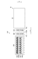
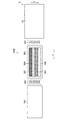
図7、及び図8は第一実施形態に係るメンテナンス部の配置が示される模式図である。図7は図1に示されたインクジェット記録装置10の上側から、メンテナンス部140、及び描画部18の周辺を見た図である。図8は図1に示されたインクジェット記録装置10の用紙搬送下流側から、メンテナンス部140、及び描画部18の周辺を見た図である。
7 and 8 are schematic views showing the arrangement of the maintenance unit according to the first embodiment. 7 is a view of the vicinity of the
図8では、図7に示された液体吐出ヘッド56C、液体吐出ヘッド56M、液体吐出ヘッド56Y、及び液体吐出ヘッド56Kのうち、液体吐出ヘッド56Kのみが図示されている。
8, only the
図7に示されたメンテナンス部140は、第一払拭部302、第二払拭部304、キャッピング部306が備えられている。また、図8に示されるように、メンテナンス部140はヘッド移動部308が備えられている。
The
図7に示された液体吐出ヘッド56C、液体吐出ヘッド56M、液体吐出ヘッド56Y、及び液体吐出ヘッド56Kは、キャッピング部306が装着されている。
The
図7、及び図8に示されたメンテナンス部140は、図3等に符号Xが付されて示された用紙幅方向と平行となる方向であるヘッド移動方向について、描画部18に近い側から第二払拭部304、第一払拭部302、キャッピング部306がこの順に配置される構造を有している。
The
ヘッド移動方向の詳細は後述する。以下、ヘッド移動方向を表す符号として、用紙幅方向を表す符号Xが用いられることとする。図7、及び図8における符号+はヘッド移動方向の正方向を表している。図7、及び図8における符号−はヘッド移動方向の負方向を表している。図8に破線を用いて示された液体吐出ヘッド56Kは、描画位置に配置される液体吐出ヘッド56Kが表されている。
Details of the head moving direction will be described later. Hereinafter, a symbol X representing the paper width direction is used as a symbol representing the head moving direction. The sign + in FIGS. 7 and 8 represents the positive direction of the head movement direction. In FIG. 7 and FIG. 8, the symbol-represents the negative direction of the head movement direction. The
第一払拭部302、及び第二払拭部304は、液体吐出ヘッド56C、液体吐出ヘッド56M、液体吐出ヘッド56Y、及び液体吐出ヘッド56Kの吐出面を清掃する手段として機能する。
The
第一払拭部302、及び第二払拭部304は、ヘッド移動方向について、描画部18とキャッピング部306との間に配置されている。キャッピング部306に近い方が第一払拭部302とされ、キャッピング部306から遠い方が第二払拭部304とされる。
The
第一払拭部302、及び第二払拭部304は、走行させたウエブ312を吐出面の同じ領域に接触させることで、吐出面の当該領域に付着したインク等の汚れの拭き取りを行う。
The
図7に示された矢印線312B、及び図8に示された矢印付きの曲線312Bは、第一払拭部302、及び第二払拭部304におけるウエブの走行方向を表している。なお、図7では、図示の都合上、第一払拭部302、及び第二払拭部304のそれぞれについて、図7における最も下のウエブのみにウエブを表す符号312、及び走行方向の符号312Bが付されている。
An
キャッピング部306は、液体吐出ヘッド56C、液体吐出ヘッド56M、液体吐出ヘッド56Y、及び液体吐出ヘッド56Kの吐出面を保護する手段として機能する。吐出面の保護の例として、吐出面に形成されるノズル部におけるインクの乾燥防止が挙げられる。
The
描画が実行されない非描画期間において、液体吐出ヘッド56C、液体吐出ヘッド56M、液体吐出ヘッド56Y、及び液体吐出ヘッド56Kは、キャッピング部306の位置であるキャッピング位置に配置される。
In the non-drawing period in which drawing is not performed, the
そして、液体吐出ヘッド56C、液体吐出ヘッド56M、液体吐出ヘッド56Y、及び液体吐出ヘッド56Kの吐出面にキャッピング部306が装着される。
Then, the
また、キャッピング部306は液体吐出ヘッド56C、液体吐出ヘッド56M、液体吐出ヘッド56Y、及び液体吐出ヘッド56Kに対してパージ処理が施される際のパージ部と兼用される。
The
パージ処理が実行されるパージ処理期間において、液体吐出ヘッド56C、液体吐出ヘッド56M、液体吐出ヘッド56Y、及び液体吐出ヘッド56Kは、キャッピング位置に配置される。
In the purge process period in which the purge process is performed, the
そして、液体吐出ヘッド56C、液体吐出ヘッド56M、液体吐出ヘッド56Y、及び液体吐出ヘッド56Kの吐出面にキャッピング部306が装着された状態で、液体吐出ヘッド56C、液体吐出ヘッド56M、液体吐出ヘッド56Y、及び液体吐出ヘッド56Kのパージ処理が実行される。
The
パージ処理とは、ノズル部に一定期間連続して正圧を与え、ノズル開口からインクを排出させる処理である。パージ処理が施されると、ノズル部内の気泡、及び異物などを排出させることが可能である。 The purge process is a process in which a positive pressure is continuously applied to the nozzle portion for a certain period to discharge ink from the nozzle opening. When the purge process is performed, it is possible to discharge bubbles and foreign matters in the nozzle portion.
一定期間の例として、駆動電圧に基づきノズル部を動作させてインクを吐出させる際のノズル部の動作期間を超える期間が挙げられる。 As an example of the fixed period, there is a period exceeding the operation period of the nozzle unit when the nozzle unit is operated based on the driving voltage to discharge ink.
ヘッド移動部308は、ヘッド移動方向について、描画が実行される描画位置と、液体吐出ヘッド56C、液体吐出ヘッド56M、液体吐出ヘッド56Y、及び液体吐出ヘッド56Kのメンテナンスが実行されるメンテナンス位置との間を、液体吐出ヘッド56C、液体吐出ヘッド56M、液体吐出ヘッド56Y、及び液体吐出ヘッド56Kを移動させる手段である。
The
ここでいうメンテナンス位置とは、図7に示されたヘッド移動方向におけるキャッピング部306が配置されるキャッピング位置、図7に示されたヘッド移動方向における第一払拭部302、及び第二払拭部304が配置されるヘッド払拭位置が含まれる。
The maintenance position here refers to the capping position where the
本実施形態におけるヘッド移動方向はキャッピング部306から描画部18へ向かう方向が正方向とされる。ヘッド移動方向は描画部18からキャッピング部306へ向かう方向が負方向とされる。
In the present embodiment, the head moving direction from the
図8に示されたヘッド移動部308の構成例として、図7に示された液体吐出ヘッド56C、液体吐出ヘッド56M、液体吐出ヘッド56Y、及び液体吐出ヘッド56Kを支持するガイド部、及びボールねじ等の移動機構が備えられる態様が挙げられる。
As a configuration example of the
図8に示されたヘッド移動部308は、図7に示された液体吐出ヘッド56C、液体吐出ヘッド56M、液体吐出ヘッド56Y、及び液体吐出ヘッド56Kのそれぞれに具備されてもよい。
The
図8に示されたヘッド移動部308は、図7に示された液体吐出ヘッド56C、液体吐出ヘッド56M、液体吐出ヘッド56Y、及び液体吐出ヘッド56Kを一括して移動させる構造とされてもよい。
The
[払拭部の詳細な説明]
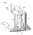
図9は払拭部の構成例が示される模式図である。図7、及び図8に示された第一払拭部302、及び第二払拭部304は、走行方向が互いに反対となる方向であることを除いて、共通の構造を適用することができる。ここでは、第一払拭部302について説明する。
[Detailed description of wiping section]
FIG. 9 is a schematic diagram showing a configuration example of the wiping unit. A common structure can be applied to the
図9に示された第一払拭部302は、ケース310にウエブ312を走行させるウエブ走行経路が形成される。ウエブ走行経路は、繰出軸314、巻取軸316、第一押圧ローラ318、第二押圧ローラ320、及びガイドローラ322が備えられている。
In the
第一押圧ローラ318、及び第二押圧ローラ320は、帯状に形成されたウエブ312が巻きかけられる。第一押圧ローラ318、及び第二押圧ローラ320は、ウエブ312を吐出面に当接させる押圧手段の機能を有している。
The first
第一押圧ローラ318、及び第二押圧ローラ320の押圧部分の材料には、シリコン、エチレン−プロピレン−ジエンゴム、又はポリウレタンなどが使用されてもよい。
Silicon, ethylene-propylene-diene rubber, polyurethane, or the like may be used as the material of the pressing portions of the first
ウエブ312の材料として、ポリエチレンテレフタラート、ポリエステル、ポリウレタン、又はナイロンなどの極微細繊維の編物、若しくは織物が使用されてもよい。
As the material of the
繰出軸314は、ウエブ312を繰り出す軸部材である。巻取軸316は、ウエブ312を巻き取る軸部材である。ガイドローラ322は、第一押圧ローラ318と第二押圧ローラ320との間において、第一押圧ローラ318から繰り出されたウエブ312であり、第二押圧ローラ320に巻き取られるウエブ312を案内するガイド部材の機能を有している。
The feeding
ウエブ312は、繰出軸314から繰り出され、第一押圧ローラ318に巻き掛けられ、ガイドローラ322に案内され、第二押圧ローラ320に巻き掛けられ、巻取軸316に巻き取られることで、ウエブ搬送経路を走行する。
The
図9に示された第一押圧ローラ318、及び第二押圧ローラ320は、図7に示された液体吐出ヘッド56C、液体吐出ヘッド56M、液体吐出ヘッド56Y、及び液体吐出ヘッド56Kの長手方向と平行となる方向に配置される。
The first
なお、液体吐出ヘッド56C、液体吐出ヘッド56M、液体吐出ヘッド56Y、及び液体吐出ヘッド56Kの長手方向は、図7に符号Xが付されて図示された用紙搬送方向と直交する方向である。
Note that the longitudinal directions of the
図9に示された第一払拭部302は、ヘッド移動方向の負方向における上流側に第一押圧ローラ318が配置され、ヘッド移動方向の負方向における下流側に第二押圧ローラ320が配置される。
In the
図9に示された第一払拭部302は、図示されない昇降部に昇降可能に取り付けられている。昇降部は、第一払拭部302を払拭退避位置と払拭処理位置との間で移動させる。払拭退避位置は払拭処理位置に対して下側とされる。
The
昇降部の構成例として、第一払拭部302を昇降可能に支持するガイド部、及びボールねじ等の移動機構が備えられる態様が挙げられる。
As an example of the configuration of the elevating unit, a mode in which a guide unit that supports the
図9に示されるように、ウエブ312に洗浄液を付与する洗浄液付与部330が備えられてもよい。図9に示された洗浄液付与部330は、ウエブ312に向けて洗浄液を噴射させる非接触の付与方式が採用される。洗浄液の付与方式は接触の付与方式が適用されてもよい。
As shown in FIG. 9, a cleaning
図9に示された洗浄液付与部330は、第一洗浄液付与部、及び第二洗浄液付与部の一態様である。
The cleaning
第二払拭部304は、図9に示された第一払拭部302におけるウエブの走行方向を反対となる方向にすればよい。例えば、第一払拭部302を吐出面と平行な面内において180度回転させてもよい。また、第一払拭部302における繰出軸314と巻取軸316との位置を入れ換えてもよい。
The
[第一実施形態に係る清掃方法の説明]
図10は第一実施形態に係る清掃方法の手順が示されるフローチャートである。ここでいう清掃は、吐出面の拭き取り、吐出面の払拭、吐出面のワイピングと読み替えることができる。以下の説明においても同様である。
[Description of Cleaning Method According to First Embodiment]
FIG. 10 is a flowchart showing the procedure of the cleaning method according to the first embodiment. Cleaning here can be read as wiping the discharge surface, wiping the discharge surface, and wiping the discharge surface. The same applies to the following description.
吐出面の清掃が開始されると、パージ工程S10においてパージ処理が実行される。図7に示された液体吐出ヘッド56C、液体吐出ヘッド56M、液体吐出ヘッド56Y、及び液体吐出ヘッド56Kが、描画位置に配置されている場合は、液体吐出ヘッド56C、液体吐出ヘッド56M、液体吐出ヘッド56Y、及び液体吐出ヘッド56Kを描画位置からキャッピング位置へ移動させるパージ前ヘッド移動工程が、図10に示されたパージ工程S10に含まれてもよい。
When cleaning of the discharge surface is started, a purge process is executed in the purge step S10. When the
パージ工程S10は省略可能である。パージ工程S10が省略される場合、パージ工程に代わり、液体吐出ヘッド56C、液体吐出ヘッド56M、液体吐出ヘッド56Y、及び液体吐出ヘッド56Kの吐出面に装着されたキャップ部が吐出面から取り外されるキャッピング解除工程が実行される。
The purge step S10 can be omitted. When the purge step S10 is omitted, instead of the purge step, capping is performed in which the cap portions attached to the ejection surfaces of the
次に、ヘッド第一移動工程S12が実行される。ヘッド第一移動工程S12では、図7に示された液体吐出ヘッド56C、液体吐出ヘッド56M、液体吐出ヘッド56Y、及び液体吐出ヘッド56Kをヘッド移動方向の正方向へ移動させる。図10ではヘッド移動方向の正方向は+X方向と記載されている。
Next, head first movement process S12 is performed. In the head first movement step S12, the
第一払拭工程S14において、図7に示された液体吐出ヘッド56C、液体吐出ヘッド56M、液体吐出ヘッド56Y、及び液体吐出ヘッド56Kの吐出面の払拭が実行される。図10に示された第一払拭工程S14は、図7に示された液体吐出ヘッド56C、液体吐出ヘッド56M、液体吐出ヘッド56Y、及び液体吐出ヘッド56Kが、第一払拭部302を用いた払拭処理領域に進入するタイミングに合わせて、第一払拭部302を払拭退避位置から上昇させ、第一払拭部302を払拭処理位置で停止させる。
In the first wiping step S14, the ejection surfaces of the
液体吐出ヘッド56C、液体吐出ヘッド56M、液体吐出ヘッド56Y、及び液体吐出ヘッド56Kが、第一払拭部302を用いた払拭処理領域を通過する際に、第一払拭部302を用いた吐出面の払拭処理が実行される。
When the
液体吐出ヘッド56C、液体吐出ヘッド56M、液体吐出ヘッド56Y、及び液体吐出ヘッド56Kが、第一払拭部302を用いた払拭処理領域を通過し終えると、第一払拭部302を払拭処理位置から下降させ、第一払拭部302を払拭退避位置で停止させる。第一払拭工程S14は、パージ処理後に、最初に第一払拭部を用いて実行される吐出面の清掃の一態様である。また、第一払拭工程S14は、パージ処理が非実行の場合に、最初に第一払拭部を用いて実行される吐出面の清掃の一態様である。
When the
図10に示された描画位置到着判断工程S16では、図7に示された液体吐出ヘッド56C、液体吐出ヘッド56M、液体吐出ヘッド56Y、及び液体吐出ヘッド56Kが、描画位置に到着したか否かが判断される。
In the drawing position arrival determination step S16 shown in FIG. 10, whether or not the
図10に示された描画位置到着判断工程S16におけるNO判定である、図7に示された液体吐出ヘッド56C、液体吐出ヘッド56M、液体吐出ヘッド56Y、及び液体吐出ヘッド56Kが描画位置に到着していないと判定されると、図10に示されたヘッド第一移動工程S12、及び第一払拭工程S14が継続される。
The
一方、描画位置到着判断工程S16におけるYES判定である、図7に示された液体吐出ヘッド56C、液体吐出ヘッド56M、液体吐出ヘッド56Y、及び液体吐出ヘッド56Kが描画位置に到着したと判定されると、図10に示されたヘッド第二移動工程S18が実行される。
On the other hand, it is determined that the
ヘッド第二移動工程S18では、図7に示された液体吐出ヘッド56C、液体吐出ヘッド56M、液体吐出ヘッド56Y、及び液体吐出ヘッド56であり、描画位置に到着した液体吐出ヘッド56C、液体吐出ヘッド56M、液体吐出ヘッド56Y、及び液体吐出ヘッド56Kをヘッド移動方向の負方向へ移動させる。図10ではヘッド移動方向の負方向は−X方向と記載されている。
In the second head moving step S18, the
第二払拭工程S20において、図7に示された液体吐出ヘッド56C、液体吐出ヘッド56M、液体吐出ヘッド56Y、及び液体吐出ヘッド56の吐出面の払拭が実行される。図10に示された第二払拭工程S20は、図7に示された液体吐出ヘッド56C、液体吐出ヘッド56M、液体吐出ヘッド56Y、及び液体吐出ヘッド56Kが第二払拭部304を用いた払拭処理領域に進入するタイミングに合わせて、第二払拭部304を払拭退避位置から上昇させ、第二払拭部304を払拭処理位置で停止させる。
In the second wiping step S20, the wiping of the ejection surfaces of the
液体吐出ヘッド56C、液体吐出ヘッド56M、液体吐出ヘッド56Y、及び液体吐出ヘッド56Kが第二払拭部304を用いた払拭処理領域を通過する際に、第二払拭部304を用いた液体吐出ヘッド56C、液体吐出ヘッド56M、液体吐出ヘッド56Y、及び液体吐出ヘッド56Kの吐出面の払拭処理が実行される。
When the
液体吐出ヘッド56C、液体吐出ヘッド56M、液体吐出ヘッド56Y、及び液体吐出ヘッド56Kが、第二払拭部304を用いた払拭処理領域を通過し終えると、第二払拭部304を払拭処理位置から下降させ、第二払拭部304を払拭退避位置で停止させる。第二払拭工程S20は、パージ処理が実行された後の第一払拭部を用いた最初の吐出面の清掃後に、第二払拭部を用いて実行される吐出面の清掃の一態様である。また、第二払拭工程S20は、パージ処理が非実行の場合の第一払拭部を用いた最初の吐出面の清掃後に、第二払拭部を用いて実行される吐出面の清掃の一態様である。
When the
図10に示されたキャッピング位置到着判断工程S22では、図7に示された液体吐出ヘッド56C、液体吐出ヘッド56M、液体吐出ヘッド56Y、及び液体吐出ヘッド56Kが、ヘッド移動経路におけるキャッピング位置に到着したか否かが判断される。
In the capping position arrival determination step S22 shown in FIG. 10, the
キャッピング位置到着判断工程S22におけるNO判定である、図7に示された液体吐出ヘッド56C、液体吐出ヘッド56M、液体吐出ヘッド56Y、及び液体吐出ヘッド56Kがキャッピング位置に到着していないと判定されると、図10に示されたヘッド第二移動工程S18、及び第二払拭工程S20が継続される。
It is determined that the
一方、キャッピング位置到着判断工程S22におけるYES判定である、図7に示された液体吐出ヘッド56C、液体吐出ヘッド56M、液体吐出ヘッド56Y、及び液体吐出ヘッド56Kがキャッピング位置に到着したと判定されると、清掃方法は終了される。
On the other hand, it is determined that the
[作用効果]
第一実施形態に係る清掃方法では、図9に示されたウエブの走行方向と、図7に示された液体吐出ヘッド56C、液体吐出ヘッド56M、液体吐出ヘッド56Y、及び液体吐出ヘッド56Kの移動方向とは反対となる方向とされる。
[Function and effect]
In the cleaning method according to the first embodiment, the traveling direction of the web shown in FIG. 9 and the movement of the
すなわち、ヘッド移動方向の正方向について、液体吐出ヘッド56C、液体吐出ヘッド56M、液体吐出ヘッド56Y、及び液体吐出ヘッド56Kを移動させる場合は、ヘッド移動方向の負方向にウエブを走行させる第一払拭部302を用いた払拭が実行される。
That is, when the
一方、ヘッド移動方向の負方向について、液体吐出ヘッド56C、液体吐出ヘッド56M、液体吐出ヘッド56Y、及び液体吐出ヘッド56Kを移動させる場合は、ヘッド移動方向の正方向にウエブを走行させる第二払拭部304を用いた払拭が実行される。
On the other hand, when the
このように、液体吐出ヘッド56C、液体吐出ヘッド56M、液体吐出ヘッド56Y、及び液体吐出ヘッド56Kの移動方向と反対の方向にウエブを走行させて吐出面を払拭し、かつ、ヘッド移動方向の正方向、及びヘッド移動方向の負方向の双方向から吐出面が払拭されることで、ヘッド移動方向、又はウエブ走行方向の片側に拭き残りが偏ることがない。
In this way, the web is run in the direction opposite to the moving direction of the
液体吐出ヘッド56C、液体吐出ヘッド56M、液体吐出ヘッド56Y、及び液体吐出ヘッド56Kの移動方向と反対の方向にウエブを走行させて吐出面を払拭することで、払拭中にウエブが緩まず、安定した払拭が可能となる。
By moving the web in the direction opposite to the moving direction of the
また、液体吐出ヘッド56C、液体吐出ヘッド56M、液体吐出ヘッド56Y、及び液体吐出ヘッド56Kにパージ処理が施された後の最初の払拭は、キャッピング部306に近い方の第一払拭部302が用いられるので、パージ処理実行の直後に吐出面が払拭可能であり、吐出面に残った残液の垂れ落ち、又は吐出面に残った残液の固化が抑制される。
The
[変形例]
本実施形態では、第一払拭部302のウエブ312の走行方向を液体吐出ヘッドの長手方向と平行となる方向としたが、第一払拭部302のウエブ312の走行方向は液体吐出ヘッドの長手方向と交差する方向とすることができる。同様に、第二払拭部304のウエブの走行方向は液体吐出ヘッドの長手方向と交差する方向とすることができる。
[Modification]
In the present embodiment, the traveling direction of the
本実施形態では、第二払拭部304のウエブの走行方向は第一払拭部302のウエブ312の走行方向と反対となる方向としたが、第二払拭部304のウエブの走行方向は第一払拭部302のウエブ312の走行方向と反対となる方向の成分を有する方向とすることができる。
In the present embodiment, the traveling direction of the web of the
本実施形態に示された第一払拭部302のウエブ312の走行方向は第一方向の一態様である。本実施形態に示された第二払拭部304のウエブの走行方向は第二方向の一態様である。
The traveling direction of the
本実施形態に示されたヘッド移動部308は相対移動部の一態様である。すなわち、液体吐出ヘッド56C、液体吐出ヘッド56M、液体吐出ヘッド56Y、及び液体吐出ヘッド56Kのヘッド移動方向についての移動は、第一払拭部と液体吐出ヘッドとの相対移動の一態様、及びに第二払拭部と液体吐出ヘッドとの相対移動の一態様である。
The
ヘッド移動部308を用いた液体吐出ヘッド56C、液体吐出ヘッド56M、液体吐出ヘッド56Y、及び液体吐出ヘッド56Kの移動方向は、相対移動方向の一態様であり、第一払拭部と液体吐出ヘッドとの相対移動における第一払拭部を基準とした液体吐出ヘッドの移動方向の一態様である。
The movement direction of the
また、ヘッド移動部308を用いた液体吐出ヘッド56C、液体吐出ヘッド56M、液体吐出ヘッド56Y、及び液体吐出ヘッド56Kの移動方向は、第二払拭部と液体吐出ヘッドとの相対移動における第二払拭部を基準とした液体吐出ヘッドの移動方向の一態様である。
The moving direction of the
ヘッド移動部308に代わり、ヘッド移動方向における位置が固定された液体吐出ヘッド56C、液体吐出ヘッド56M、液体吐出ヘッド56Y、及び液体吐出ヘッド56Kに対して、第一払拭部302、及び第二払拭部304をヘッド移動方向について移動させる相対移動部が備えられてもよい。
Instead of the
また、ヘッド移動部308に代わり、ヘッド移動方向について、第一払拭部302、及び第二払拭部304と、液体吐出ヘッド56C、液体吐出ヘッド56M、液体吐出ヘッド56Y、及び液体吐出ヘッド56Kの両者を移動させる相対移動部が備えられてもよい。
Further, instead of the
本実施形態には、第一払拭部302を用いた吐出面の払拭の際のヘッド移動方向が、第一払拭部302のウエブ312の走行方向と反対となる方向とされる態様を例示したが、第一払拭部302を用いた吐出面の払拭の際のヘッド移動方向は第一払拭部302のウエブ312の走行方向と反対となる方向の成分を有する方向とすることができる。
In this embodiment, the mode in which the head moving direction at the time of wiping the ejection surface using the
同様に、第二払拭部304を用いた吐出面の払拭の際のヘッド移動方向は第二払拭部304のウエブの走行方向と反対となる方向の成分を有する方向とすることができる。
Similarly, the head moving direction when wiping the ejection surface using the
ここに示した変形例は、以下に説明する第二実施形態、第三実施形態、及び第四実施形態にも適用可能である。 The modification shown here is applicable also to 2nd Embodiment, 3rd Embodiment, and 4th Embodiment which are demonstrated below.
[ウエブの払拭期間中吸収量の説明]
本実施形態に係るメンテナンス部140は、第一払拭部302のウエブ312の払拭期間中吸収量である第一払拭期間中吸収量Q1と、第二払拭部304のウエブ払拭期間中吸収量である第二払拭期間中吸収量Q2との関係が、次式
Q1≧Q2
を満たしている。
[Description of absorbed amount during web wiping period]
Meet.
本実施形態に示された第一払拭期間中吸収量Q1は第一清掃期間中吸収量Q1に相当する。本実施形態に示された第二払拭期間中吸収量Q2は第二清掃期間中吸収量Q2に相当する。 The first wiping period during absorption Q 1 shown in the present embodiment corresponds in the absorption Q 1 first cleaning period. Second wiping period during absorption Q 2 to which was shown in the present embodiment corresponds in the absorption Q 2 second cleaning period.
第一払拭部302のウエブ312の払拭期間中吸収量Q1とは、第一払拭部302を用いた吐出面277の払拭期間中に第一払拭部302のウエブ312が吸収できる液体吸収量である。液体吸収量は液体の体積で表される。また、第二払拭部304のウエブの払拭期間中吸収量Q2とは、第二払拭部304を用いた吐出面277の払拭期間中に第二払拭部304のウエブが吸収できる液体の体積である。
The wiping period during absorption to Q 1 web 312 of the
図11、及び図12はウエブの払拭期間中吸収量の説明図である。図11は、吐出面における任意の位置BHの払拭が開始されるタイミングt0における模式図である。図12は、吐出面における任意の位置BHの払拭が開始されたタイミングt0から、期間t1が経過したタイミングにおける模式図である。位置DWは図11に示されたタイミングt0において位置BHを払拭したウエブにおける位置である。 11 and 12 are explanatory diagrams of the amount of absorption during the wiping period of the web. FIG. 11 is a schematic diagram at timing t 0 when wiping of an arbitrary position B H on the ejection surface is started. FIG. 12 is a schematic diagram at a timing when a period t 1 has elapsed from a timing t 0 at which wiping of an arbitrary position B H on the ejection surface is started. Position D W is the position in the web to dispel the position B H at the timing t 0 shown in FIG. 11.
図11では、便宜上、ウエブに符号312Aが付されている。図11に示されたウエブ312は、図9に示された第一払拭部302に具備されるウエブ312、又は第二払拭部304に具備されるウエブを表している。
In FIG. 11, the web is denoted by
また、図11では、便宜上、液体吐出ヘッドに符号56が付されている。図11に示された液体吐出ヘッド56は、図7に示された液体吐出ヘッド56C、液体吐出ヘッド56M、液体吐出ヘッド56Y、及び液体吐出ヘッド56Kのいずれかを表している。
In FIG. 11, the liquid ejection head is denoted by
ウエブ312Aの払拭期間中吸収量は、以下の式により表される。以下の式におけるVWはウエブ312Aと液体吐出ヘッドの吐出面が接触している領域におけるウエブ312Aの走行速度の絶対値であり、VBはウエブ312Aと液体吐出ヘッドの吐出面が接触している領域における液体吐出ヘッドとウエブ312Aとの相対速度の絶対値である。また、Aは吐出面に当接させるウエブ312Aの長さであるウエブ312Aのニップ幅であり、Q0はウエブ312Aの走行方向における単位長さあたりの吸収量である。
The amount of absorption during the wiping period of the
以下、VWはウエブ312Aの走行速度と記載する。また、VBは液体吐出ヘッド56とウエブ312Aとの相対速度と記載する。ウエブ312Aと液体吐出ヘッドが接触している領域は、第一払拭部材と吐出面が接触している領域の一態様である。ウエブ312Aと液体吐出ヘッドが接触している領域は、第二払拭部材と吐出面が接触している領域の一態様である。
Hereinafter, V W is described as the traveling speed of the
ウエブの払拭期間中吸収量={1+(VW/VB)}×A×Q0
なお、矢印付きの曲線により示されたウエブ312Aの走行方向と、矢印線により示された液体吐出ヘッド56の移動方向と反対となる方向として、ウエブ312Aの走行速度VW、及び液体吐出ヘッド56とウエブ312Aとの相対速度VBの方向が定められている。
Absorption amount during web wiping period = {1+ (V W / V B )} × A × Q 0
In addition, the traveling speed V W of the
上記式を用いて払拭期間中のウエブ312Aの吸収量が定義される理由は以下のとおりである。タイミングt0からタイミングt1までの期間tにおいて、吐出面277の任意の位置BHを払拭するウエブ312Aの長さTは、T=A+VW×tである。
The reason why the absorption amount of the
また、期間tはt=A/VBと表される。そうすると、吐出面277の任意の位置BHを払拭するウエブ312Aの長さTは、T=A+VW×A/VB={1+(VW/VB)}×Aと表される。吐出面277の任意の位置BHを払拭するウエブ312Aの長さTに、ウエブ312Aの走行方向における単位長さあたりの吸収量Qを乗算することで、払拭期間中のウエブ312Aの吸収量が求められる。
A period t is expressed as t = A / V B. Then, the length T of the
ウエブ312Aの走行方向における単位長さあたりの吸収量Q0は、ウエブ312Aの種類に応じた固定値である。ここでいうウエブ312Aの種類は、ウエブ312Aの材質でもよいし、ウエブ312Aの構造でもよい。ウエブの構造として、空隙の大小、織りの種類、編みの種類などが挙げられる。
The amount of absorption Q 0 per unit length in the running direction of the
第一払拭部302のウエブ312の走行速度をVW1、液体吐出ヘッド56と第一払拭部302のウエブ312との相対速度をVB1、第一払拭部302のウエブ312のニップ幅をA1、第一払拭部302のウエブ312の走行方向における単位長さあたりの吸収量をQ01とすると、第一払拭期間中吸収量Q1は、次式
Q1={1+(VW1/VB1)}×A1×Q01
と表される。
The traveling speed of the
It is expressed.
同様に、第二払拭部304のウエブの走行速度をVW2、液体吐出ヘッド56と第二払拭部304のウエブとの相対速度をVB2、第二払拭部304のウエブのニップ幅をA2、第二払拭部304のウエブの走行方向における単位長さあたりの吸収量をQ02とすると、第二払拭期間中吸収量Q2は、次式
Q2={1+(VW2/VB2)}×A2×Q02
と表される。
Similarly, the running speed of the web of the
It is expressed.
そして、第一払拭部302のウエブ312の払拭期間中吸収量Q1≧第二払拭部304のウエブの払拭期間中吸収量Q2とされ、払拭期間中吸収量が相対的に多い第一払拭部302のウエブ312を用いてパージ処理の直後の払拭が行われることで、吐出面の残液が確実に吸収される。
Then, the absorption amount Q 1 during the wiping period of the
ここでいうパージ処理の直後の払拭とは、図10に示されたパージ工程S10が実行される場合における、パージ工程が実行された後の最初の吐出面の払拭である。 The wiping immediately after the purging process here is wiping of the first ejection surface after the purging process is performed when the purging process S10 shown in FIG. 10 is performed.
更に、払拭期間中吸収量が相対的に少ない第二払拭部304のウエブを用いて最終の払拭が行われることで、図6に示されたノズル部281からのウエブによるインクの引き出しが抑制された結果、図6に示されたノズル部281のメニスカスが維持されるので、その後に実行される描画における吐出を安定させうる。
Furthermore, the final wiping is performed using the web of the
ここでいう最終払拭は、図10に示されたパージ工程S10が実行される場合における、パージ工程が実行された後の最初の吐出面の払拭の他の払拭としてもよい。最終払拭は、パージ工程S10が非実行の場合の払拭が含まれていてもよい。 The final wiping here may be other wiping of the first ejection surface after the purging process is performed when the purging process S10 shown in FIG. 10 is performed. The final wiping may include wiping when the purging step S10 is not executed.
第一払拭期間中吸収量Q1≧第二払拭期間中吸収量Q2を実現するには、第一払拭部302のウエブ312の走行速度VW1と、第二払拭部304のウエブの走行速度VW2とを調整してもよい。
In order to realize the absorption amount Q 1 during the first wiping period ≧ the absorption amount Q 2 during the second wiping period, the traveling speed V W1 of the
また、第一払拭部302のウエブ312と、第二払拭部304のウエブとの種類を変えて、第一払拭部302のウエブ312の走行方向における単位長さあたりの吸収量Q01と、第二払拭部304のウエブの走行方向における単位長さあたりの吸収量Q02とを調整してもよい。
Further, the
[洗浄液付与量について]
図9に示された洗浄液付与部330が備えられる場合に、洗浄液の付与量が以下のとおりとされてもよい。洗浄液付与部330が用いられた第一払拭部302のウエブ312への洗浄液付与、及び洗浄液付与部330が用いられた第二払拭部304のウエブへの洗浄液付与は洗浄液付与工程の一態様である。
[About amount of cleaning solution applied]
When the cleaning
パージ後の最初の払拭における第一払拭部302のウエブ312への洗浄液付与量である第一洗浄液付与量をP1pとし、パージが非実行の払拭における第一払拭部302のウエブ312への洗浄液付与量である第二洗浄液付与量をP1nとし、パージ後の最終の払拭における第二払拭部304のウエブへの洗浄液付与量である第三洗浄液付与量をP2pとし、パージが非実行の払拭における第二払拭部304のウエブへの洗浄液付与量である第四洗浄液付与量をP2nとした場合に、第一洗浄液付与量P1p、第二洗浄液付与量P1n、及び第三洗浄液付与量P2pは、次式
0≦P1p<P2p≦P1n
を満たす。
The first cleaning liquid application amount that is the cleaning liquid application amount to the
Meet.
また、第一洗浄液付与量P1p、第二洗浄液付与量P1n、及び第四洗浄液付与量P2nは、次式
0≦P1p<P2n≦P1n
を満たす。
In addition, the first cleaning liquid application amount P 1p , the second cleaning liquid application amount P 1n , and the fourth cleaning liquid application amount P 2n are expressed by the following equations: 0 ≦ P 1p <P 2n ≦ P 1n
Meet.
但し、P2pとP2nとの大小関係は、P2<P2n、P2p=P2n、P2p>P2nのいずれでもよい。 However, the magnitude relationship between P 2p and P 2n may be any of P 2 <P 2n , P 2p = P 2n , and P 2p > P 2n .
上記の如く洗浄液付与量を規定することで以下の効果を得ることできる。パージ処理後の最初の払拭における第一払拭部302を用いた払拭は、主として、パージ処理の結果、吐出面に残った残液の拭き取りが目的であるので、第一洗浄液付与量P1pは相対的に少なくてもよい。洗浄液を非付与としてもよい。
The following effects can be obtained by defining the cleaning liquid application amount as described above. The wiping using the
第一払拭期間中吸収量Q1≧第二払拭期間中吸収量Q2の場合、パージ処理が非実行の場合における第一払拭部302を用いた払拭は、第二払拭部304を用いた払拭よりも液体が多く吸収されるので、第一払拭部302のウエブ312に予め洗浄液を相対的に多く付与しておくことで、パージ処理が非実行の場合における第一払拭部302を用いた払拭において、図6に示されたノズル部281からのインクの引き出しが抑制される。
When the absorption amount Q 1 during the first wiping period is equal to or greater than the absorption amount Q 2 during the second wiping period, wiping using the
第一払拭期間中吸収量Q1≧第二払拭期間中吸収量Q2の場合、第二払拭部304を用いた払拭は、第一払拭部302を用いた払拭よりも、図6に示されたノズル部281からインクが引き出される可能性が低いので、第三洗浄液付与量P2p、及び第四洗浄液付与量P2nは、第一洗浄液付与量P1pを超え、第二洗浄液付与量P1n未満とすることができる。
When the absorption amount Q 1 during the first wiping period is equal to or greater than the absorption amount Q 2 during the second wiping period, wiping using the
[第二実施形態]
次に、第二実施形態について説明する。以下の説明では、主として、第一実施形態との違いについて説明する。また、第一実施形態と同一の構成の説明は適宜省略する。
[Second Embodiment]
Next, a second embodiment will be described. In the following description, differences from the first embodiment will be mainly described. Further, the description of the same configuration as that of the first embodiment is omitted as appropriate.
図13は第二実施形態に係るメンテナンス部の配置が示される模式図である。図13は図7と同様に、図1に示されたインクジェット記録装置10の上側から、メンテナンス部140A、及び描画部18の周辺を見た図である。
FIG. 13 is a schematic diagram showing the arrangement of the maintenance unit according to the second embodiment. FIG. 13 is a view of the periphery of the
図13に示されるメンテナンス部140Aは、ヘッド退避部340が備えられている。図13に示されるメンテナンス部140Aは、ヘッド移動方向について、描画部18から近い方から、キャッピング部306、第一払拭部302、第二払拭部304、ヘッド退避部340の順に配置されている。
The
図13に示されたメンテナンス部140Aにおけるヘッド移動方向の正方向は、キャッピング部306からヘッド退避部340へ向かう方向である。また、ヘッド移動方向の負方向は、ヘッド退避部340からキャッピング部306へ向かう方向である。
The positive direction of the head movement direction in the
図14は第二実施形態に係る清掃方法の手順が示されるフローチャートである。図14に示されるフローチャートでは、図10に示された描画位置到着判断工程S16に代わり、ヘッド退避位置到着判断工程S106が示されている。 FIG. 14 is a flowchart showing the procedure of the cleaning method according to the second embodiment. In the flowchart shown in FIG. 14, a head withdrawal position arrival determination step S106 is shown instead of the drawing position arrival determination step S16 shown in FIG.
図14に示されたヘッド退避位置到着判断工程S106は、ヘッド第一移動工程S102、第一払拭工程S104の実行中に、液体吐出ヘッド56C、液体吐出ヘッド56M、液体吐出ヘッド56Y、及び液体吐出ヘッド56Kが、図13に示されたヘッド退避部340の位置であるヘッド退避位置に到着したか否かが判断される。
In the head retraction position arrival determination step S106 shown in FIG. 14, the
図14に示されたパージ工程S100、ヘッド第一移動工程S102、及び第一払拭工程S104は、それぞれ図10に示されたパージ工程S10、ヘッド第一移動工程S12、及び第一払拭工程S14に対応している。 The purge step S100, the head first moving step S102, and the first wiping step S104 shown in FIG. 14 are respectively replaced with the purge step S10, the head first moving step S12, and the first wiping step S14 shown in FIG. It corresponds.
図14に示されたヘッド退避位置到着判断工程S106において、NO判定である液体吐出ヘッド56C、液体吐出ヘッド56M、液体吐出ヘッド56Y、及び液体吐出ヘッド56Kがヘッド退避位置に到着していないと判定されると、ヘッド第一移動工程S102、及び第一払拭工程S104が継続される。
In the head withdrawal position arrival determination step S106 shown in FIG. 14, it is determined that the
一方、ヘッド退避位置到着判断工程S106におけるYES判定である、液体吐出ヘッド56C、液体吐出ヘッド56M、液体吐出ヘッド56Y、及び液体吐出ヘッド56Kがヘッド退避位置に到着したと判定されると、ヘッド第二移動工程S108が実行される。
On the other hand, if it is determined as YES in the head withdrawal position arrival determination step S106 that the
図14に示されたヘッド第二移動工程S108、第二払拭工程S110、及びキャッピング位置到着判断工程S112は、図10に示されたヘッド第二移動工程S18、第二払拭工程S20、及びキャッピング位置到着判断工程S22に対応している。 The head second moving step S108, the second wiping step S110, and the capping position arrival determining step S112 shown in FIG. 14 are the head second moving step S18, the second wiping step S20, and the capping position shown in FIG. This corresponds to the arrival determination step S22.
[作用効果]
図13に示されたメンテナンス部140Aを備えた液体吐出装置によれば、液体吐出ヘッド56M、液体吐出ヘッド56Y、及び液体吐出ヘッド56Kのメンテナンス中に、描画部18を用いた描画が実行される描画領域へ、液体吐出ヘッド56M、液体吐出ヘッド56Y、及び液体吐出ヘッド56Kを配置させずに済む。
[Function and effect]
According to the liquid ejection apparatus provided with the
一般に、描画部18は、その前後に乾燥処理が施される乾燥処理部が配置されるので、乾燥処理部から発生される熱によって描画部18が高温になっている場合がありうるので、液体吐出ヘッド56M、液体吐出ヘッド56Y、及び液体吐出ヘッド56Kのメンテナンス中に、描画部18の周囲の熱に起因する液体吐出ヘッド56M、液体吐出ヘッド56Y、及び液体吐出ヘッド56Kの乾燥劣化が抑制される。
In general, since the
[第三実施形態]
次に、第二実施形態について説明する。以下の説明では、主として、第二実施形態との違いについて説明する。また、第一実施形態、及び第二実施形態と同一の構成の説明は適宜省略する。
[Third embodiment]
Next, a second embodiment will be described. In the following description, differences from the second embodiment will be mainly described. Moreover, the description of the same configuration as the first embodiment and the second embodiment is omitted as appropriate.
図15は第三実施形態に係るメンテナンス部の配置が示される模式図である。図15は図7と同様に、図1に示されたインクジェット記録装置10の上側から、メンテナンス部140B、及び描画部18の周辺を見た図である。
FIG. 15 is a schematic diagram showing the arrangement of the maintenance unit according to the third embodiment. FIG. 15 is a view of the periphery of the
図15に示されたメンテナンス部140Bは、ヘッド移動方向について、キャッピング部306のヘッド退避部340の側に第一払拭部302が配置される。
In the
また、メンテナンス部140Bは、ヘッド移動方向について、キャッピング部306の描画部18の側に第二払拭部304が配置される。図15に示されたメンテナンス部140Bにおけるヘッド移動方向の正方向は、キャッピング部306からヘッド退避部340へ向かう方向である。また、ヘッド移動方向の負方向は、ヘッド退避部340からキャッピング部306へ向かう方向である。
In the
図16は第三実施形態に係る清掃方法の手順が示されるフローチャートである。図16に示されたフローチャートでは、図14に示されたキャッピング位置到着判断工程S112に代わり、描画位置到着判断工程S212を有している。 FIG. 16 is a flowchart showing the procedure of the cleaning method according to the third embodiment. The flowchart shown in FIG. 16 has a drawing position arrival determination step S212 instead of the capping position arrival determination step S112 shown in FIG.
図16におけるパージ工程S200、ヘッド第一移動工程S202、第一払拭工程S204、ヘッド退避位置到着判断工程S206、ヘッド第二移動工程S208、第二払拭工程S210は、それぞれ図14に示されたパージ工程S100、ヘッド第一移動工程S102、第一払拭工程S104、ヘッド退避位置到着判断工程S106、ヘッド第二移動工程S108、第二払拭工程S110に対応している。 The purge process S200, the head first movement process S202, the first wiping process S204, the head withdrawal position arrival determination process S206, the head second movement process S208, and the second wiping process S210 in FIG. This corresponds to step S100, head first movement step S102, first wiping step S104, head retracted position arrival determination step S106, head second movement step S108, and second wiping step S110.
すなわち、第三実施形態に係る清掃方法では、ヘッド移動方向の正方向について、キャッピング部306からヘッド退避部340へ液体吐出ヘッド56C、液体吐出ヘッド56M、液体吐出ヘッド56Y、及び液体吐出ヘッド56Kを移動させる際に、第一払拭工程S204が実行される。
That is, in the cleaning method according to the third embodiment, the
また、ヘッド移動方向の負方向について、ヘッド退避部340からキャッピング部306を通過させ、描画部18へ液体吐出ヘッド56C、液体吐出ヘッド56M、液体吐出ヘッド56Y、及び液体吐出ヘッド56Kを移動させる際に、第二払拭工程S210が実行される。
Further, in the negative direction of the head movement direction, when the
図15に示されたメンテナンス部140Bを備えた液体吐出装置によれば、第二払拭工程S210の実行後は、描画部18を用いた描画が実行される描画領域へ液体吐出ヘッド56C、液体吐出ヘッド56M、液体吐出ヘッド56Y、及び液体吐出ヘッド56Kを移動させるので、メンテナンス処理の終了後に直ちに描画を行うことが可能となる。
According to the liquid ejection apparatus including the
[第四実施形態]
次に、第四実施形態について説明する。以下の説明では、主として、第三実施形態との違いについて説明する。また、第一実施形態、第二実施形態、及び第三実施形態と同一の構成の説明は適宜省略する。
[Fourth embodiment]
Next, a fourth embodiment will be described. In the following description, differences from the third embodiment will be mainly described. The description of the same configuration as that of the first embodiment, the second embodiment, and the third embodiment is omitted as appropriate.
図17は第四実施形態に係るメンテナンス部の配置が示される模式図である。図17は図7と同様に、図1に示されたインクジェット記録装置10の上側から、メンテナンス部140B、及び描画部18の周辺を見た図である。
FIG. 17 is a schematic diagram showing the arrangement of the maintenance unit according to the fourth embodiment. FIG. 17 is a view of the vicinity of the
図17に示されたメンテナンス部140Cは、図15に示されたメンテナンス部140Bの第一払拭部302の位置と、第二払拭部304の位置とが入れ替えられている。
In the
図17に示されたヘッド移動方向の正方向は、キャッピング部306から描画部18へ向かう方向である。また、ヘッド移動方向の負方向は、キャッピング部306からヘッド退避部340へ向かう方向である。
The positive direction of the head movement direction shown in FIG. 17 is the direction from the
図18は第四実施形態に係る清掃方法の手順が示されるフローチャートである。図18に示されたフローチャートでは、図17に示されたキャッピング部306から描画部18へ液体吐出ヘッド56C、液体吐出ヘッド56M、液体吐出ヘッド56Y、及び液体吐出ヘッド56Kを移動させる際に、図18に示された第一払拭工程S304が実行される。
FIG. 18 is a flowchart showing the procedure of the cleaning method according to the fourth embodiment. In the flowchart shown in FIG. 18, when the
そして、図16に示されたヘッド退避位置到着判断工程S206に代わり、図18に示された描画位置到着判断工程S306が実行される。 Then, instead of the head withdrawal position arrival determination step S206 shown in FIG. 16, a drawing position arrival determination step S306 shown in FIG. 18 is executed.
また、図18に示されたフローチャートでは、図17に示されたキャッピング部306からヘッド退避部340へ液体吐出ヘッド56C、液体吐出ヘッド56M、液体吐出ヘッド56Y、及び液体吐出ヘッド56Kを移動させる際に、図18に示された第二払拭工程S310が実行される。そして、図16に示された描画位置到着判断工程S212に代わり、図18に示されたヘッド退避位置到着判断工程S312が実行される。
In the flowchart shown in FIG. 18, when the
図18におけるパージ工程S300、ヘッド第一移動工程S302、ヘッド第二移動工程S308は、それぞれ図16におけるパージ工程S200、ヘッド第一移動工程S202、ヘッド第二移動工程S208に対応している。 The purge process S300, the first head movement process S302, and the second head movement process S308 in FIG. 18 correspond to the purge process S200, the first head movement process S202, and the second head movement process S208 in FIG. 16, respectively.
図17に示されたメンテナンス部140Cを備えた液体吐出装置によれば、第二払拭部304を装置の搬送部から離すことができる。一般的に最終の払拭を実行する第二払拭部304の方が、第一払拭部302に比べてウエブの消費が早い。
According to the liquid ejection apparatus including the
そして、第二払拭部304のみを用いるメンテナンスが実行される場合もありうる。そのため、第二払拭部304のウエブの方が、第一払拭部302のウエブ312よりも交換頻度が高い。
And the maintenance using only the
図16に示された構成により、描画実行中でも第二払拭部304のウエブを交換することが可能である。
With the configuration shown in FIG. 16, it is possible to replace the web of the
[変形例の説明]
上述した第一実施形態から第四実施形態では、吐出面を払拭する払拭部材としてウエブを例示したが、吐出面を払拭する払拭部材はブレード、ワイパーなどが適用されてもよい。上述した第一実施形態から第四実施形態に示されたウエブ312は第一払拭部材の一態様である。第二払拭部304のウエブは第二払拭部材の一態様である。
[Description of modification]
In the first to fourth embodiments described above, the web is exemplified as the wiping member for wiping the discharge surface. However, a blade, a wiper, or the like may be applied to the wiping member for wiping the discharge surface. The
上述した第一実施形態から第四実施形態では、四つの液体吐出ヘッドを備えたインクジェット記録装置を例示したが、液体吐出ヘッドの数は四つ未満でもよいし、四つを超えていてもよい。 In the first embodiment to the fourth embodiment described above, the ink jet recording apparatus including four liquid discharge heads is illustrated, but the number of liquid discharge heads may be less than four or may exceed four. .
上述した第一実施形態から第四実施形態では、四つの液体吐出ヘッドのそれぞれについて、第一払拭部、及び第二払拭部が具備される態様を例示したが、第一払拭部、及び第二払拭部の数は、液体吐出ヘッドの数未満でもよいし、液体吐出ヘッドの数を超えてもよい。 In the first embodiment to the fourth embodiment described above, the first wiping portion and the second wiping portion are exemplified for each of the four liquid ejection heads. The number of wiping units may be less than the number of liquid ejection heads or may exceed the number of liquid ejection heads.
第一払拭部、及び第二払拭部の数が液体吐出ヘッドの数未満の場合、第一払拭部、及び第二払拭部を液体吐出ヘッドの位置へ移動させる構成を付加すればよい。 When the number of the first wiping unit and the second wiping unit is less than the number of the liquid ejection heads, a configuration for moving the first wiping unit and the second wiping unit to the position of the liquid ejection head may be added.
以上説明した本発明の実施形態は、本発明の趣旨を逸脱しない範囲で、適宜構成要件を変更、追加、削除することが可能である。本発明は以上説明した実施形態に限定されるものではなく、本発明の技術的思想内で当該分野の通常の知識を有するものにより、多くの変形が可能である。 In the embodiment of the present invention described above, the configuration requirements can be appropriately changed, added, and deleted without departing from the spirit of the present invention. The present invention is not limited to the embodiments described above, and many modifications are possible by those having ordinary knowledge in the field within the technical idea of the present invention.
10 インクジェット記録装置
11 搬送系
12 給紙部
14 処理液付与部
16 処理液乾燥処理部
18 描画部
20 インク乾燥処理部
24 排紙部
30 給紙台
32 サッカー装置
34 給紙ローラ対
36 フィーダボード
36A リテーナ
36B ガイドローラ
38 前当て
40 給紙胴
40A、42A、46A、52A、64D グリッパー
40B、42B、46B、52B 回転軸
42 処理液胴
42C、46C、52C 外周面
44 処理液付与装置
46 処理液乾燥処理胴
48 用紙搬送ガイド
50 処理液乾燥処理ユニット
52 描画胴
54 用紙押さえローラ
56、56C、56M、56Y、56K 液体吐出ヘッド
58 インラインセンサ
64 チェーングリッパー
64A 第一スプロケット
64B 第二スプロケット
64C チェーン
68 インク乾燥処理ユニット
72、73 ガイドプレート
76 排紙台
100 システムコントローラ
100A CPU
100B ROM
100C RAM
102 通信部
103 ホストコンピュータ
104 画像メモリ
110 搬送制御部
112 給紙制御部
114 処理液付与制御部
116 処理液乾燥制御部
118 描画制御部
120 インク乾燥制御部
124 排紙制御部
130 操作部
132 表示部
134 パラメータ記憶部
136 プログラム格納部
138 メンテナンス制御部
140、140A、140B、140C メンテナンス部
200 ヘッドモジュール
210 流路構造体
214 インク供給路
216 個別供給路
218 圧力室
220 ノズル連通路
226 循環個別流路
228 循環共通流路
230 圧電素子
231 圧電体層
232 インク供給室
236 インク循環室
252 供給管路
256 循環管路
264 上部電極
265 下部電極
266 振動板
267 接着層
275 ノズル板
277 吐出面
280 ノズル開口
281 ノズル部
302 第一払拭部
304 第二払拭部
306 キャッピング部
308 ヘッド移動部
310 ケース
312、312A ウエブ
314 繰出軸
316 巻取軸
318 第一押圧ローラ
320 第二押圧ローラ
322 ガイドローラ
330 洗浄液付与部
340 ヘッド退避部
S 用紙
S10〜S22、S100〜S112、S200〜S212、S300〜S312 清掃方法の工程
DESCRIPTION OF
100B ROM
100C RAM
102
Claims (15)
前記メンテナンス部は、第一払拭部材を第一方向に走行させて前記吐出面を清掃する第一払拭部と、
第二払拭部材を前記第一方向と反対の方向の成分を有する第二方向に走行させて前記吐出面を清掃する第二払拭部と、
前記第一払拭部と前記液体吐出ヘッドとを相対的に移動させ、かつ、前記第二払拭部と前記液体吐出ヘッドとを相対的に移動させる相対移動部と、
を備え、
前記メンテナンス制御部は、前記第一払拭部を用いた前記吐出面の清掃の際に、前記相対移動部を用いた前記第一払拭部と前記液体吐出ヘッドとの相対移動における前記第一払拭部を基準とする前記液体吐出ヘッドの移動方向を前記第一方向と反対の方向の成分を有する方向として、前記第一払拭部と前記液体吐出ヘッドとを相対移動させ、
前記第二払拭部を用いた前記吐出面の清掃の際に、前記相対移動部を用いた前記第二払拭部と前記液体吐出ヘッドとの相対移動における前記第二払拭部を基準とする前記液体吐出ヘッドの移動方向を前記第二方向と反対の方向の成分を有する方向として、前記第二払拭部と前記液体吐出ヘッドとを相対移動させて、前記第一払拭部、及び前記第二払拭部を用いて前記吐出面の同じ領域を清掃させる液体吐出装置。 A liquid discharge apparatus including a liquid discharge head having a discharge surface on which a discharge port for discharging a liquid is formed, a maintenance unit that performs maintenance of the liquid discharge head, and a maintenance control unit that controls the operation of the maintenance unit. There,
The maintenance unit is a first wiping unit that cleans the discharge surface by running a first wiping member in a first direction;
A second wiping unit that cleans the discharge surface by running the second wiping member in a second direction having a component in a direction opposite to the first direction;
A relative movement unit that relatively moves the first wiping unit and the liquid ejection head, and relatively moves the second wiping unit and the liquid ejection head;
With
The maintenance control unit includes the first wiping unit in relative movement between the first wiping unit using the relative movement unit and the liquid ejection head when cleaning the ejection surface using the first wiping unit. The direction of movement of the liquid discharge head with reference to the direction having a component in the direction opposite to the first direction, the first wiping unit and the liquid discharge head are relatively moved,
The liquid based on the second wiping unit in the relative movement between the second wiping unit using the relative movement unit and the liquid ejection head during cleaning of the ejection surface using the second wiping unit. The first wiping unit and the second wiping unit are configured such that the movement direction of the ejection head is a direction having a component opposite to the second direction, and the second wiping unit and the liquid ejection head are relatively moved. A liquid ejecting apparatus that cleans the same region of the ejection surface using
前記第一払拭部、前記第二払拭部、及び前記パージ部は、前記相対移動部の相対移動方向について、前記パージ部、前記第一払拭部、及び前記第二払拭部の順に配置される請求項1に記載の液体吐出装置。 The maintenance unit includes a purge unit that performs a purge process of the liquid discharge head,
The first wiping unit, the second wiping unit, and the purge unit are arranged in the order of the purge unit, the first wiping unit, and the second wiping unit in the relative movement direction of the relative movement unit. Item 2. The liquid ejection device according to Item 1.
前記ヘッド退避部、前記第一払拭部、前記第二払拭部、及び前記パージ部は、前記相対移動部の相対移動方向について、前記ヘッド退避部、前記第二払拭部、前記第一払拭部、及び前記パージ部の順に配置される請求項2又は3に記載の液体吐出装置。 The maintenance unit includes a head retracting unit that retracts the liquid ejection head,
The head retracting unit, the first wiping unit, the second wiping unit, and the purge unit are configured to move the head retracting unit, the second wiping unit, the first wiping unit with respect to the relative movement direction of the relative moving unit, The liquid ejection device according to claim 2, wherein the liquid ejection device is disposed in the order of the purge unit.
Q1≧Q2
の関係を有し、
前記メンテナンス制御部は、前記パージ部を用いた前記液体吐出ヘッドのパージ処理が実行された後に、最初に前記第一払拭部を用いて前記吐出面の清掃を実行させ、前記第一払拭部を用いた前記最初の前記吐出面の清掃後に、前記第二払拭部を用いて前記吐出面の清掃を実行させる請求項2から5のいずれか一項に記載の液体吐出装置。 The first during cleaning periods absorption is a liquid absorption amount of the first wiping member in the cleaning period using the first wiping portion as Q 1, the second wiping member in the cleaning period using the second wiping portion Assuming that the absorption amount during the second cleaning period, which is the liquid absorption amount, is Q 2 , the absorption amount Q 1 during the first cleaning period and the absorption amount Q 2 during the second cleaning period are expressed by the following formula: Q 1 ≧ Q 2
Have the relationship
The maintenance control unit first causes the first wiping unit to perform cleaning of the ejection surface after the liquid ejection head purge process using the purge unit is performed, and the first wiping unit is 6. The liquid ejection device according to claim 2, wherein after the used first ejection surface is cleaned, the ejection surface is cleaned using the second wiping unit. 6.
{1+(VW1/VB1)}×A1×Q01
により表され、
前記第二払拭部材と前記吐出面が接触している領域における前記第二払拭部材の走行速度の絶対値をVW2とし、前記第二払拭部材と前記吐出面が接触している領域における前記液体吐出ヘッドと前記第二払拭部材との相対速度の絶対値をVB2とし、前記第二払拭部を用いた前記吐出面の清掃の際に、前記吐出面に接触させる前記第二払拭部材の走行方向における前記第二払拭部材の長さであるニップ幅をA2とし、前記第二払拭部材の走行方向における前記第二払拭部材の単位長さあたりの吸収量をQ02とすると、前記第二清掃期間中吸収量Q2は、次式
{1+(VW2/VB2)}×A2×Q02
により表される請求項6に記載の液体吐出装置。 The absolute value of the traveling speed of the first wiping member in the region where the first wiping member and the ejection surface are in contact is V W1, and the liquid in the region where the first wiping member and the ejection surface are in contact with each other. The absolute value of the relative speed between the ejection head and the first wiping member is V B1, and the first wiping member is brought into contact with the ejection surface when the ejection surface is cleaned using the first wiping unit. When the nip width is the length of the first wiping member in the direction to the a 1, the absorption amount per unit length of the first wiping member in the traveling direction of the first wiping member and Q 01, the first during the cleaning period absorption Q 1 is, the following equation {1+ (V W1 / V B1 )} × A 1 × Q 01
Represented by
The absolute value of the traveling speed of the second wiping member in the region where the second wiping member and the ejection surface are in contact is V W2, and the liquid in the region where the second wiping member and the ejection surface are in contact with each other. The absolute value of the relative speed between the ejection head and the second wiping member is V B2, and the second wiping member is brought into contact with the ejection surface when the ejection surface is cleaned using the second wiping unit. When the nip width is the length of the second wiping member in the direction as a 2, the absorption amount per unit length of the second wiping member in the traveling direction of the second wiping member and Q 02, the second The amount of absorption Q 2 during the cleaning period is given by the following formula {1+ (V W2 / V B2 )} × A 2 × Q 02
The liquid ejection device according to claim 6 represented by:
前記メンテナンス制御部は、前記第一洗浄液付与部を用いて前記第一払拭部材に洗浄液を付与し、かつ、前記第二洗浄液付与部を用いて前記第二払拭部材に洗浄液を付与する際に、前記パージ部を用いたパージ処理が実行された後の前記第一払拭部を用いた最初の前記吐出面の清掃における前記第一払拭部材への洗浄液付与量である第一洗浄液付与量をP1pとし、前記パージ部を用いたパージ処理が非実行の場合の前記第一払拭部を用いた前記吐出面の清掃における前記第一払拭部材への洗浄液付与量である第二洗浄液付与量をP1nとし、前記パージ部を用いたパージ処理が実行された場合の前記第二払拭部を用いた前記吐出面の清掃における前記第二払拭部材への洗浄液付与量である第三洗浄液付与量をP2pとすると、前記第一洗浄液付与量P1p、前記第二洗浄液付与量P1n、及び前記第三洗浄液付与量P2pの関係は、次式
0≦P1p<P2p≦P1n
により表される関係を満たす請求項6又は7に記載の液体吐出装置。 The maintenance unit includes a first cleaning liquid application unit that applies a cleaning liquid to the first wiping member, and a second cleaning liquid application unit that applies a cleaning liquid to the second wiping member,
The maintenance control unit applies the cleaning liquid to the first wiping member using the first cleaning liquid application unit, and applies the cleaning liquid to the second wiping member using the second cleaning liquid application unit. A first cleaning liquid application amount that is a cleaning liquid application amount to the first wiping member in the first cleaning of the discharge surface using the first wiping unit after the purge process using the purge unit is performed is P 1p And the second cleaning liquid application amount that is the cleaning liquid application amount to the first wiping member in the cleaning of the discharge surface using the first wiping unit when the purge process using the purge unit is not executed is P 1n P 2p is the third cleaning liquid application amount that is the cleaning liquid application amount to the second wiping member in the cleaning of the discharge surface using the second wiping unit when the purge process using the purge unit is executed. Then, the first washing Liquid application amount P 1p, the second cleaning liquid deposition amount P 1n, and the relationship of the third cleaning liquid deposition amount P 2p has the formula 0 ≦ P 1p <P 2p ≦ P 1n
The liquid ejecting apparatus according to claim 6, wherein the liquid ejection device satisfies the relationship represented by:
0≦P1p<P2n≦P1n
により表される関係を満たす請求項8に記載の液体吐出装置。 The maintenance control unit applies the cleaning liquid to the first wiping member using the first cleaning liquid application unit, and applies the cleaning liquid to the second wiping member using the second cleaning liquid application unit. When the fourth cleaning liquid application amount that is the cleaning liquid application amount to the second wiping member in the cleaning of the discharge surface using the second wiping unit when the purge process using the purge unit is not executed is P 2n. The relationship between the first cleaning liquid application amount P 1p , the second cleaning liquid application amount P 1n , and the fourth cleaning liquid application amount P 2n is as follows: 0 ≦ P 1p <P 2n ≦ P 1n
The liquid ejecting apparatus according to claim 8, satisfying a relationship represented by:
前記液体吐出ヘッドと、第一払拭部材を第一方向に走行させる第一払拭部とを相対移動させて前記吐出面を清掃する第一払拭工程と、
前記液体吐出ヘッドと、第二払拭部材を前記第一方向と反対の方向の成分を有する第二方向に走行させる第二払拭部とを相対移動させて前記吐出面を清掃する第二払拭工程と、
を含み、
前記第一払拭工程は、前記第一払拭部と前記液体吐出ヘッドとの相対移動における前記第一払拭部を基準とする前記液体吐出ヘッドの移動方向を前記第一方向と反対の方向の成分を有する方向として、前記第一払拭部と前記液体吐出ヘッドとを相対移動させ、
前記第二払拭工程は、前記第二払拭部と前記液体吐出ヘッドとの相対移動における前記第二払拭部を基準とする前記液体吐出ヘッドの移動方向を前記第二方向と反対の方向の成分を有する方向として、前記第二払拭部と前記液体吐出ヘッドとを相対移動させ、
前記第一払拭工程、及び前記第二払拭工程は、前記第一払拭部、及び前記第二払拭部を用いて前記吐出面の同じ領域を清掃させる清掃方法。 A method of cleaning the discharge surface of a liquid discharge head having a discharge surface on which a discharge port for discharging liquid is formed,
A first wiping step for cleaning the ejection surface by relatively moving the liquid ejection head and a first wiping portion that causes the first wiping member to travel in a first direction;
A second wiping step for cleaning the ejection surface by relatively moving the liquid ejection head and a second wiping portion that causes the second wiping member to travel in a second direction having a component opposite to the first direction; ,
Including
In the first wiping step, a component in a direction opposite to the first direction is defined as a movement direction of the liquid ejection head with reference to the first wiping portion in relative movement between the first wiping portion and the liquid ejection head. As a direction to have, the first wiping unit and the liquid ejection head are relatively moved,
The second wiping step includes a component in a direction opposite to the second direction with respect to the movement direction of the liquid ejection head with respect to the second wiping portion in the relative movement between the second wiping portion and the liquid ejection head. As a direction to have, the second wiping unit and the liquid ejection head are relatively moved,
The first wiping step and the second wiping step are cleaning methods for cleaning the same region of the ejection surface using the first wiping portion and the second wiping portion.
前記第一払拭工程、及び前記パージ工程は、前記第一払拭部を基準とする前記液体吐出ヘッドの移動方向を前記第一方向と反対の方向の成分を有する方向について前記第一払拭部と前記液体吐出ヘッドとを相対移動させる場合に、前記第一払拭工程、及び前記パージ工程の順に実行され、
前記第二払拭工程、及び前記パージ工程は、前記第二払拭部を基準とする前記液体吐出ヘッドの移動方向を前記第二方向と反対の方向の成分を有する方向について前記第二払拭部と前記液体吐出ヘッドとを相対移動させる場合に、前記パージ工程、及び前記第二払拭工程の順に実行される請求項10に記載の清掃方法。 A purge step of performing a purge process of the liquid discharge head,
In the first wiping step and the purging step, the first wiping unit and the direction with respect to a direction having a component in a direction opposite to the first direction with respect to the moving direction of the liquid ejection head with respect to the first wiping unit. When relatively moving the liquid ejection head, the first wiping step and the purge step are performed in this order,
In the second wiping step and the purging step, the moving direction of the liquid ejection head with respect to the second wiping portion as a reference has a component in a direction opposite to the second direction, The cleaning method according to claim 10, wherein when the liquid discharge head is relatively moved, the purge process and the second wiping process are executed in this order.
Q1≧Q2
の関係を有し、
前記パージ工程が実行された後に、最初に前記第一払拭工程を実行させ、前記最初の前記第一払拭工程の後に、前記第二払拭工程を実行させる請求項11に記載の清掃方法。 The first during cleaning periods absorption is a liquid absorption amount of the first wiping member and Q 1 in the cleaning period of the first wiping step, the liquid absorption amount of the second wiping member in the cleaning period of the second wiping step in it the second during the cleaning period absorption and Q 2, the first during the cleaning period and absorption Q 1 and the second during the cleaning period absorption Q 2 are the formula Q 1 ≧ Q 2
Have the relationship
The cleaning method according to claim 11, wherein the first wiping step is first executed after the purge step is executed, and the second wiping step is executed after the first wiping step.
{1+(VW1/VB1)}×A1×Q01
により表され、
前記第二払拭工程は、前記第二払拭部材と前記吐出面が接触している領域における前記第二払拭部材の走行速度の絶対値をVW2とし、前記第二払拭部材と前記吐出面が接触している領域における前記液体吐出ヘッドと前記第二払拭部材との相対速度の絶対値をVB2とし、前記第二払拭工程の際に前記吐出面に接触させる前記第二払拭部材の走行方向における前記第二払拭部材の長さであるニップ幅をA2とし、前記第二払拭部材の走行方向における前記第二払拭部材の単位長さあたりの吸収量をQ02とすると、前記第二清掃期間中吸収量Q2が、次式
{1+(VW2/VB2)}×A2×Q02
により表される請求項12に記載の清掃方法。 In the first wiping step, the absolute value of the traveling speed of the first wiping member in a region where the first wiping member and the ejection surface are in contact is set to V W1, and the first wiping member and the ejection surface are in contact with each other. The absolute value of the relative speed between the liquid ejection head and the first wiping member in the area being set is V B1, and the first wiping member is brought into contact with the ejection surface during the first wiping step in the traveling direction. which is a long nip width of said first wiping member and a 1, if the absorption per unit length of said first wiping member in the traveling direction of the first wiping member and Q 01, the first cleaning period The intermediate absorption Q 1 is expressed by the following formula {1+ (V W1 / V B1 )} × A 1 × Q 01
Represented by
In the second wiping step, the absolute value of the traveling speed of the second wiping member in a region where the second wiping member and the discharge surface are in contact is set to VW2, and the second wiping member and the discharge surface are in contact with each other. The absolute value of the relative speed between the liquid ejection head and the second wiping member in the area where the wiping operation is performed is V B2, and the second wiping member is brought into contact with the ejection surface during the second wiping step in the traveling direction. said the length nip width of the second wiping member and a 2, when the absorption amount per unit length of the second wiping member in the traveling direction of the second wiping member and Q 02, the second cleaning period The intermediate absorption amount Q 2 is represented by the following formula {1+ (V W2 / V B2 )} × A 2 × Q 02
The cleaning method of Claim 12 represented by these.
前記洗浄液付与工程は、前記パージ工程が実行された後の最初の前記第一払拭工程における前記第一払拭部材への洗浄液付与量である第一洗浄液付与量をP1pとし、前記パージ工程が非実行の場合の前記第一払拭工程における前記第一払拭部材への洗浄液付与量である第二洗浄液付与量をP1nとし、前記パージ工程が実行された場合の前記第二払拭工程における前記第二払拭部材への洗浄液付与量である第三洗浄液付与量をP2pとすると、前記第一洗浄液付与量P1p、前記第二洗浄液付与量P1n、及び前記第三洗浄液付与量P2pの関係は、次式
0≦P1p<P2p≦P1n
により表される関係を満たす請求項12又は13に記載の清掃方法。 Including a cleaning liquid application step of applying a cleaning liquid to the first wiping member and the second wiping member;
In the cleaning liquid application process, the first cleaning liquid application amount that is the cleaning liquid application amount to the first wiping member in the first first wiping process after the purge process is executed is set to P 1p , and the purge process is not performed. The second cleaning liquid application amount, which is the cleaning liquid application amount to the first wiping member in the first wiping step in the case of execution, is set to P 1n, and the second wiping step in the second wiping step when the purge process is executed. When the third cleaning liquid application amount is the cleaning liquid deposition amount of the wiping member and P 2p, the first cleaning liquid deposition amount P 1p, the second cleaning liquid deposition amount P 1n, and the relationship of the third cleaning liquid deposition amount P 2p is The following formula 0 ≦ P 1p <P 2p ≦ P 1n
The cleaning method according to claim 12 or 13, satisfying the relationship represented by:
0≦P1p<P2n≦P1n
により表される関係を満たす請求項14に記載の清掃方法。 The cleaning liquid application step uses the second wiping unit when the purge process is not executed when the cleaning liquid is applied to the first wiping member and the cleaning liquid is applied to the second wiping member. When the fourth cleaning liquid application amount that is the cleaning liquid application amount to the second wiping member in cleaning the discharge surface is P 2n , the first cleaning liquid application amount P 1p , the second cleaning liquid application amount P 1n , and the fourth The relationship of the cleaning liquid application amount P 2n is as follows: 0 ≦ P 1p <P 2n ≦ P 1n
The cleaning method according to claim 14, satisfying the relationship represented by:
Priority Applications (3)
| Application Number | Priority Date | Filing Date | Title |
|---|---|---|---|
| JP2016024024A JP6501405B2 (en) | 2016-02-10 | 2016-02-10 | Liquid discharge apparatus and cleaning method |
| EP17155208.6A EP3208092B1 (en) | 2016-02-10 | 2017-02-08 | Liquid ejection device and cleaning method |
| US15/428,148 US9878546B2 (en) | 2016-02-10 | 2017-02-09 | Liquid ejection device and cleaning method |
Applications Claiming Priority (1)
| Application Number | Priority Date | Filing Date | Title |
|---|---|---|---|
| JP2016024024A JP6501405B2 (en) | 2016-02-10 | 2016-02-10 | Liquid discharge apparatus and cleaning method |
Publications (3)
| Publication Number | Publication Date |
|---|---|
| JP2017140779A true JP2017140779A (en) | 2017-08-17 |
| JP2017140779A5 JP2017140779A5 (en) | 2018-07-05 |
| JP6501405B2 JP6501405B2 (en) | 2019-04-17 |
Family
ID=57995124
Family Applications (1)
| Application Number | Title | Priority Date | Filing Date |
|---|---|---|---|
| JP2016024024A Active JP6501405B2 (en) | 2016-02-10 | 2016-02-10 | Liquid discharge apparatus and cleaning method |
Country Status (3)
| Country | Link |
|---|---|
| US (1) | US9878546B2 (en) |
| EP (1) | EP3208092B1 (en) |
| JP (1) | JP6501405B2 (en) |
Cited By (1)
| Publication number | Priority date | Publication date | Assignee | Title |
|---|---|---|---|---|
| JP2019142145A (en) * | 2018-02-22 | 2019-08-29 | 株式会社リコー | Wiping-out device, head maintenance device and liquid-discharging device |
Families Citing this family (2)
| Publication number | Priority date | Publication date | Assignee | Title |
|---|---|---|---|---|
| JP6896502B2 (en) * | 2017-05-01 | 2021-06-30 | キヤノン株式会社 | Inkjet recording device and processing liquid holding unit |
| CN109986885A (en) * | 2017-12-29 | 2019-07-09 | Tcl集团股份有限公司 | A kind of wiping arrangement and wiping method of ink jet printing head |
Citations (4)
| Publication number | Priority date | Publication date | Assignee | Title |
|---|---|---|---|---|
| US20100091065A1 (en) * | 2008-10-15 | 2010-04-15 | Hewlett-Packard Development Company Lp | Translatable web support |
| JP2010234667A (en) * | 2009-03-31 | 2010-10-21 | Fujifilm Corp | Head cleaning method and apparatus |
| JP2015039781A (en) * | 2013-08-20 | 2015-03-02 | 富士フイルム株式会社 | Wiping device |
| JP2016002708A (en) * | 2014-06-17 | 2016-01-12 | 富士フイルム株式会社 | Maintenance device, maintenance method and liquid discharge device |
Family Cites Families (10)
| Publication number | Priority date | Publication date | Assignee | Title |
|---|---|---|---|---|
| US8342639B2 (en) * | 2009-03-31 | 2013-01-01 | Fujifilm Corporation | Head cleaning method and head cleaning apparatus |
| JP2011006798A (en) | 2009-06-23 | 2011-01-13 | Brother Industries Ltd | Sewing machine |
| JP5377188B2 (en) | 2009-09-24 | 2013-12-25 | 富士フイルム株式会社 | Liquid discharge head cleaning apparatus and ink jet recording apparatus |
| JP5421318B2 (en) * | 2011-03-28 | 2014-02-19 | 富士フイルム株式会社 | Inkjet head cleaning system and inkjet head maintenance method |
| JP5653371B2 (en) * | 2012-01-06 | 2015-01-14 | 富士フイルム株式会社 | Nozzle surface cleaning device and image recording device |
| EP2620287B1 (en) * | 2012-01-25 | 2019-01-09 | Neopost Technologies | Wiping device for an ink jet franking machine |
| JP6135197B2 (en) * | 2013-03-07 | 2017-05-31 | セイコーエプソン株式会社 | Liquid ejector |
| JP2015011272A (en) | 2013-07-01 | 2015-01-19 | 株式会社リコー | Projection optical device and image projection device |
| JP5997112B2 (en) * | 2013-08-06 | 2016-09-28 | 富士フイルム株式会社 | Cleaning device |
| JP6379480B2 (en) | 2013-12-09 | 2018-08-29 | セイコーエプソン株式会社 | Liquid ejector |
-
2016
- 2016-02-10 JP JP2016024024A patent/JP6501405B2/en active Active
-
2017
- 2017-02-08 EP EP17155208.6A patent/EP3208092B1/en active Active
- 2017-02-09 US US15/428,148 patent/US9878546B2/en active Active
Patent Citations (4)
| Publication number | Priority date | Publication date | Assignee | Title |
|---|---|---|---|---|
| US20100091065A1 (en) * | 2008-10-15 | 2010-04-15 | Hewlett-Packard Development Company Lp | Translatable web support |
| JP2010234667A (en) * | 2009-03-31 | 2010-10-21 | Fujifilm Corp | Head cleaning method and apparatus |
| JP2015039781A (en) * | 2013-08-20 | 2015-03-02 | 富士フイルム株式会社 | Wiping device |
| JP2016002708A (en) * | 2014-06-17 | 2016-01-12 | 富士フイルム株式会社 | Maintenance device, maintenance method and liquid discharge device |
Cited By (2)
| Publication number | Priority date | Publication date | Assignee | Title |
|---|---|---|---|---|
| JP2019142145A (en) * | 2018-02-22 | 2019-08-29 | 株式会社リコー | Wiping-out device, head maintenance device and liquid-discharging device |
| JP7069813B2 (en) | 2018-02-22 | 2022-05-18 | 株式会社リコー | Wiping device, head maintenance device, liquid discharge device |
Also Published As
| Publication number | Publication date |
|---|---|
| EP3208092A1 (en) | 2017-08-23 |
| JP6501405B2 (en) | 2019-04-17 |
| US20170225471A1 (en) | 2017-08-10 |
| EP3208092B1 (en) | 2019-02-06 |
| US9878546B2 (en) | 2018-01-30 |
Similar Documents
| Publication | Publication Date | Title |
|---|---|---|
| JP5473704B2 (en) | Test pattern printing method and inkjet recording apparatus | |
| US20120236071A1 (en) | Cleaning apparatus and liquid ejection apparatus and cleaning method | |
| JP6625484B2 (en) | Nozzle surface wiping device, liquid ejection device, and head cleaning method | |
| US7467845B2 (en) | Image forming apparatus | |
| JP2010214653A (en) | Delivering face cleaning device, liquid delivering device, and method for cleaning delivering face | |
| US9457562B2 (en) | Liquid ejection device and dummy jet method | |
| WO2016051844A1 (en) | Drying apparatus, drying method, and program and image forming apparatus for drying | |
| WO2014148475A1 (en) | Liquid discharge device, and head cleaning method | |
| JP6501405B2 (en) | Liquid discharge apparatus and cleaning method | |
| JP6537114B2 (en) | Liquid discharge apparatus and head maintenance method | |
| WO2015060060A1 (en) | Inkjet recording device and medium transport method | |
| JP6121634B2 (en) | Wiping mechanism, droplet discharge device, wiping method | |
| CN103847235A (en) | High-speed digital inkjet printer | |
| JP6530132B2 (en) | Liquid discharge apparatus and medium floating countermeasure method | |
| WO2015015991A1 (en) | Conveyance device, image-forming device, and medium conveyance method | |
| JP6608963B2 (en) | Image forming system | |
| JP5975576B2 (en) | Image forming apparatus and image forming method | |
| JP2014213483A (en) | Maintenance method of liquid discharge head, and liquid discharge device | |
| JP5911779B2 (en) | Image recording apparatus and control method thereof | |
| JP2015058582A (en) | Droplet discharge device | |
| JP2021008034A (en) | Printing apparatus and printing method | |
| JP6878157B2 (en) | Manufacturing method of droplet ejection head, manufacturing method of image forming apparatus, droplet ejection head and image forming apparatus | |
| WO2015174224A1 (en) | Prediction information-presenting device, prediction information-presenting method, prediction information-presenting program, print control device, print control method and print control program | |
| US10752026B2 (en) | Liquid jetting apparatus and method of coping with floating of medium | |
| WO2018143125A1 (en) | Image formation device and image formation method |
Legal Events
| Date | Code | Title | Description |
|---|---|---|---|
| A621 | Written request for application examination |
Free format text: JAPANESE INTERMEDIATE CODE: A621 Effective date: 20180312 |
|
| A521 | Request for written amendment filed |
Free format text: JAPANESE INTERMEDIATE CODE: A523 Effective date: 20180524 |
|
| A131 | Notification of reasons for refusal |
Free format text: JAPANESE INTERMEDIATE CODE: A131 Effective date: 20181214 |
|
| A977 | Report on retrieval |
Free format text: JAPANESE INTERMEDIATE CODE: A971007 Effective date: 20181219 |
|
| A521 | Request for written amendment filed |
Free format text: JAPANESE INTERMEDIATE CODE: A523 Effective date: 20190201 |
|
| TRDD | Decision of grant or rejection written | ||
| A01 | Written decision to grant a patent or to grant a registration (utility model) |
Free format text: JAPANESE INTERMEDIATE CODE: A01 Effective date: 20190315 |
|
| A61 | First payment of annual fees (during grant procedure) |
Free format text: JAPANESE INTERMEDIATE CODE: A61 Effective date: 20190318 |
|
| R150 | Certificate of patent or registration of utility model |
Ref document number: 6501405 Country of ref document: JP Free format text: JAPANESE INTERMEDIATE CODE: R150 |
|
| R250 | Receipt of annual fees |
Free format text: JAPANESE INTERMEDIATE CODE: R250 |
|
| R250 | Receipt of annual fees |
Free format text: JAPANESE INTERMEDIATE CODE: R250 |
|
| R250 | Receipt of annual fees |
Free format text: JAPANESE INTERMEDIATE CODE: R250 |